KLOE-2 INTEGRATION
20
KLOE-2 INTEGRATION E.Dané on behalf of the KLOE-2 collaboration. Laboratori Nazionali di Frascati Frascati 20/11/2012 45° LNF Scientific Committee
Transcript of KLOE-2 INTEGRATION

KLOE-2
INTEGRATION
E.Dané
on behalf of the KLOE-2 collaboration.
Laboratori Nazionali di Frascati
Frascati
20/11/2012
45° LNF Scientific Committee
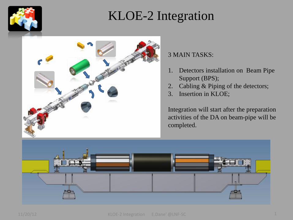
3 MAIN TASKS:
1. Detectors installation on Beam Pipe
Support (BPS);
2. Cabling & Piping of the detectors;
3. Insertion in KLOE;
KLOE-2 Integration
Integration will start after the preparation
activities of the DA on beam-pipe will be
completed.
11/20/12 KLOE-2 Integration E.Dane' @LNF-SC 1

General Activities
• New Beam Pipe Support;
• New BP (sphere);
• Check rails and extraction tools;
• Design of the QF control;
• Shell Modifications;
• BP Cooling design and construction;
Preparation for BP extraction
• Restricted Area set up;
• Endcaps opening;
• Magnets disassembling;
• Rails preparation and alignement;
• BP extraction and parking in the clean area;
Beam Pipe activities
• BP sphere check
disassembling;
• BPS e- disassembling;
• BPS e+ disassembling;
• BP soldering;
• Tungsten insertion;
• New BPS installation;
Acc
eler
ato
r D
ivis
ion
11/20/12 KLOE-2 Integration E.Dane' @LNF-SC 2

KLOE-2 FINAL GOAL
11/20/12 KLOE-2 Integration E.Dane' @LNF-SC 3

Integration Procedure: general tasks
A very detailed schedule under
study to find the critical points.
A Mockup is used to get trained on
all of these activities;
INT. WEST SIDE (IT GAS IN )
IT Support_2 Installation
Soldering BP-QD0_2
COOLING_2 Piping
CCALT_2 Installation
CCALT_2 Cabling
Beam Position Monitor_2
IP Temp. Sensors_2
Isobutane sniffer tubes
IT INSERTION
IT Insertion Tool
IT Traslation Tool
IT Temp Sensor
IT Insertion in Shifted Pos.
INT. EAST SIDE (OUT GAS IN )
IT Support_1 Installation
Soldering BP-QD0_1
COOLING_1 Piping
CCALT_1 Installation
CCALT_1 Cabling
Beam Position Monitor_1
IP Temp. Sensors_1
Isobutane sniffer tubes
IT in Nom. Pos.
Alignment Ref. Installation 1,2
QCALT INSTALLATION
QCALT_1 Installation tool
QCALT_1 Installation
QCALT_2 Installatin Tool
QCALT_2 Installation
QCALT_1,2 cabling
QCALT_1,2 cabling test
IT CABLING AND TEST
PREPARATION FOR INSERTION
Beam Pipe alignment survey
Shell Installation
Beam Pipe Transport
West side Sphere East side
11/20/12 KLOE-2 Integration E.Dane' @LNF-SC 4

KLOE-2 WEST side Integration
IT Support Installation
Quadrupole QD0
IP
BP Cooling Sphere- QD0 welding
CCALT Connectors
CCALT Modules
INT. WEST SIDE (IT GAS IN )
IT Support_2 Installation
Soldering BP-QD0_2
COOLING_2 Piping
CCALT_2 Installation
CCALT_2 Cabling
Beam Position Monitor_2
IP Temp. Sensors_2
Isobutane sniffer tubes
Old Sphere
11/20/12 KLOE-2 Integration E.Dane' @LNF-SC 5

IT Installation
Insertion of IT involves the use
of two structures:
- Translation Tool;
- Insertion Tool;.
IT INSTALLATION
IT Insertion Tool
IT Traslation Tool
IT Temp Sensor
IT Insertion in Shifted Pos.
11/20/12 KLOE-2 Integration E.Dane' @LNF-SC 6

KLOE-2 EAST Side Integration
IT shifted
Once the IT is in the shifted position it is possible to start the Integration of the East side. The procedure is symmetrical to the one of the West side.
After the installation of the East side IT is shifted back to the nominal position. Beam Pipe alignment Reference Tools are installed.
INT. EAST SIDE (OUT GAS IN )
IT Support_1 Installation
Soldering BP-QD0_1
COOLING_1 Piping
CCALT_1 Installation
CCALT_1 Cabling
Beam Position Monitor_1
IP Temp. Sensors_1
Isobutane sniffer tubes
IT in Nom. Pos.
Alignment Ref. Installation 1,2
CCALT_1
11/20/12 KLOE-2 Integration E.Dane' @LNF-SC 7

QCALT Installation
QC
AL
T In
stallation
To
ol
QCALT INSTALLATION
QCALT_1 Installation tool
QCALT_1 Installation
QCALT_2 Installatin Tool
QCALT_2 Installation
QCALT_1,2 cabling
QCALT_1,2 cabling test
Each QCALT consists of two halves.
A special tool will be used to intagrate the QCALT on the beam pipe. QCALT half part
11/20/12 KLOE-2 Integration E.Dane' @LNF-SC 8
50 mm

IP Temperature
Due to the fact that IT is sensitive to temperatures above 30
degrees, the area of the IP has been continuously monitored.
We have placed 5 temp. sensors to measure the air in the
inner region and other 4 temp. sensors in contact with the
beam pipe.
T1 T2 T3
T4 T5
Start of Airflow Test
Air Temp above the chamber
Since October 16th air at room temperature is flowing in the
IP region.
A decrease of the air temperature of about 2 degrees is observed,
while the temp. on BP got stabilized to reasonable values
Plot of the air temperature close to the IP.
Temp. on BP is stabilized
Plo
t of
the
QD
0 t
emper
atu
re.
11/20/12 KLOE-2 Integration E.Dane' @LNF-SC 9

IP Cooling: two parallel systems.
IP AIR COOLING
A liquid cooling system is under study by the DA (G. Sensolini).
All the cooling pipes (air and liquid) pass through the Beam pipe Support.
Air cooling test was made in
July using the IP Mockup:
Power applied: 40W;
Air flow: 300 l/min;
ΔT decreasing from 30°C to
25.5 C°;
Airflow in order to cool down
the inner part of IT;
IP WATER COOLING
IT QCALT
Cold Airflow
11/20/12 KLOE-2 Integration E.Dane' @LNF-SC 10

Cabling&Piping
CAVI PER LATO Num. Diam. [mm] Num. IT HV Eq Area/Cable [mm^2] Area/Cable*coeff. [mm^2] Area Tot [mm^2] Area Tot*Coeff. [mm^2] densità [kg/m] Peso [kg] Volume [L]
CCALT
CCALT_SGN 72 2,4 19 4,5 5,9 325,7 423,4 0,0071 3,328 2,752
IT
IT_HV 69 9,0 69 63,6 82,7 4389,6 5706,5 0,1000 44,850 37,092
IT_SGN 90 8,0 80 50,3 65,3 4523,9 5881,1 0,0790 46,222 38,227
IT_GAS 36 5,0 20 19,6 25,5 706,9 918,9 0,0309 7,222 5,973
TOT IT 195 169 173,6 12506,4 220,004
QCALT*
QCALT_SGN 48 5,9 32 110,4 143,52 5299,2 6889,0 0,0434 13,536 44,778
LET
LET_SGN 40 1,2 5 1,1 1,5 45,2 58,8 0,0018 0,462 0,382
SERVICES
TEMP. SENSOR 5 1,2 1 1,1 1,5 5,7 7,4 0,0018 0,058 0,048
AIR COOLING 20 6,0 13 28,3 36,8 565,5 735,1 0,0444 5,778 4,778
LIQ. COOLING 2 5,0 1 19,6 1,0 302,8 1,9
BEAM POSITION MON. 4
TOT 386 409 33128,5 121,456 354,035
Preliminary study was made to evaluate the space available for cabling and piping.
2 critical zones: B and C.
A B C QCALT IT
11/20/12 KLOE-2 Integration E.Dane' @LNF-SC 11

Critical Zone B: IT - QCALT
We are studing a cable map to
arrange the IT cables on the QCALT. Aluminum holders
glued on QCALT
surface modules.
Only 50mm distance available to connect the IT cables and arrange it on QCALT. First attempt on cabling
to learn how to arrange
the IT cables on QCALT.
QCALT IT
11/20/12 KLOE-2 Integration E.Dane' @LNF-SC 12
QCALT IT
IT cables
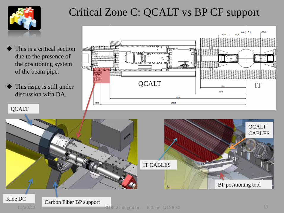
Critical Zone C: QCALT vs BP CF support
This is a critical section
due to the presence of
the positioning system
of the beam pipe.
This issue is still under
discussion with DA.
Kloe DC Carbon Fiber BP support
QCALT
QCALT IT
IT CABLES
BP positioning tool
QCALT
CABLES
11/20/12 KLOE-2 Integration E.Dane' @LNF-SC 13

Step 1. Installation of the rails; Step 2. Insertion of the 1st part of the beam guide;
Step 3. Insertion of the beam guide in the Kloe DC;
Step 4. Shell installation;
Beam-Pipe Insertion (I)
11/20/12 KLOE-2 Integration E.Dane' @LNF-SC 14

8. Removal of the the shell
9. Installation of LET detector;
Step 5. Connecting the shell and insertion of the BP;
Step 7. Removal of the beam guide;
Step 6. Traslation of the BP in nominal position;
More critical point
Beam-Pipe Insertion (I)
11/20/12 KLOE-2 Integration E.Dane' @LNF-SC 15

Insertion of the beam guide in the Kloe DC;
Inse
rtio
n o
f th
e 1
st p
art
of
bea
m g
uid
e;
Shell installation and transport BP on rails; Traslation of the BP to the nominal position;
PREVIOUS
INSTALLATION

KLOE-2 INTEGRATION GANTT
In total 33 working days (1,5 months) necessary for integration activity.
22 days devoted to the cabling and test of the IT detector.
K L O E - 2 I N T E G R A T I O N E . D A N E ' @ L N F - S C

1. Detectors Installation on Beam Pipe Assembly of IT Insertion Tool Assembly of QCALT Insertion Tool 2. Cabling & Piping of the detectors Air Cooling Piping Liquid Cooling Piping Complete Cable Strategy Study on critical zones Completion of Mockup on critical zones CCALT Connectors holders Cable Box 3. Beam Pipe insertion in Kloe Check of insertion system Sensor for the shell removal (under discussion with DA)
ACTIVITIES IN PROGRESS FOR
INTEGRATION TASK
11/20/12 KLOE-2 Integration E.Dane' @LNF-SC 18

Conclusions
• Plans for Kloe integration almost ready;
• Mockup for cabling and cooling systems done;
• Critical points related to the interference with Dafne
under study:
– Cabling in the beam pipe support region;
– Insertion inside Kloe;
A lot of work in front of us for the next months in cooperation with AD experts!
11/20/12 KLOE-2 Integration E.Dane' @LNF-SC 19