KLM summary P. Pakhlov (ITEP) Status of Geant4 simulation of scintillator KLM Status of Geant4...
16
KLM summary P. Pakhlov (ITEP) Status of Geant4 simulation of scintillator KLM by Gallina PAKHLOVA (ITEP) Optimization of the endcap acceptance by Roman MIZUK (ITEP) Read out electronics tests by Dmitry LIVENTSEV(ITEP) Mechanical structure for endcap KLM by Pasha PAKHLOV (ITEP) P a r a l l e l - A : K L M Place: KEK Room: 3-go-kan seminar hall Dates: Wednesday 08 July 2009 15:30 Parallel-A: KLM
-
Upload
pamela-clarke -
Category
Documents
-
view
219 -
download
0
Transcript of KLM summary P. Pakhlov (ITEP) Status of Geant4 simulation of scintillator KLM Status of Geant4...
KLM summary
P. Pakhlov (ITEP)
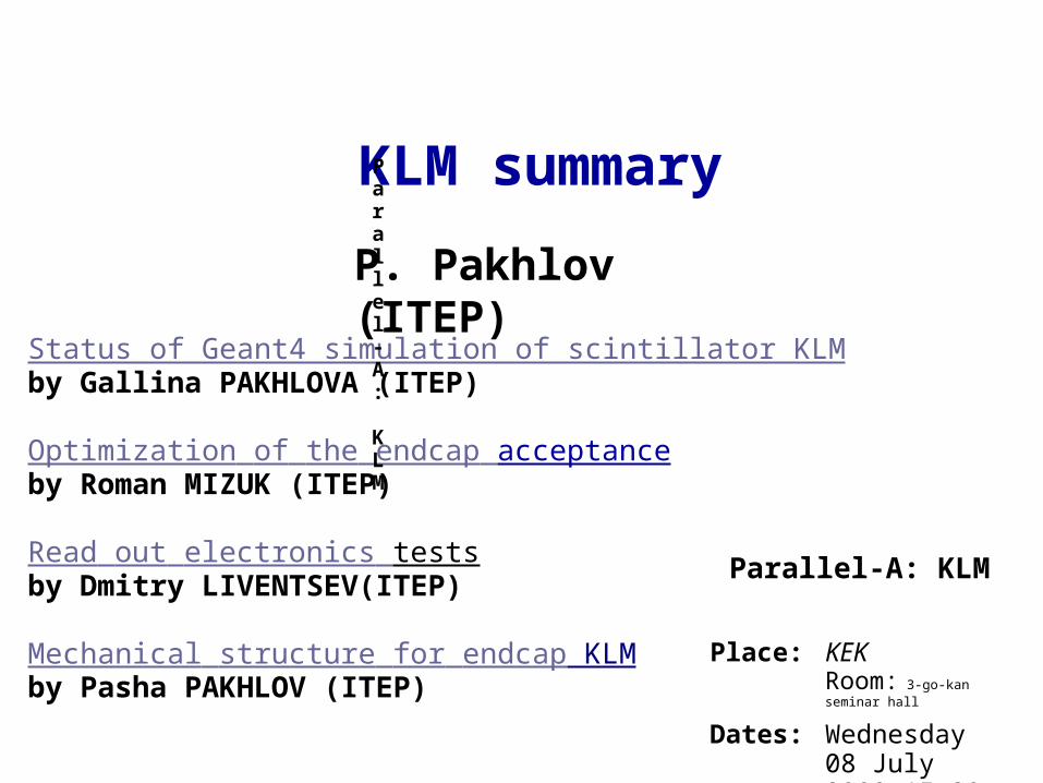
Status of Geant4 simulation of scintillator KLMby Gallina PAKHLOVA (ITEP)
Optimization of the endcap acceptanceby Roman MIZUK (ITEP)
Read out electronics testsby Dmitry LIVENTSEV(ITEP)
Mechanical structure for endcap KLMby Pasha PAKHLOV (ITEP)
Parallel-A: KLM
Place: KEKRoom: 3-go-kan seminar hall
Dates: Wednesday 08 July 2009 15:30
Parallel-A: KLM
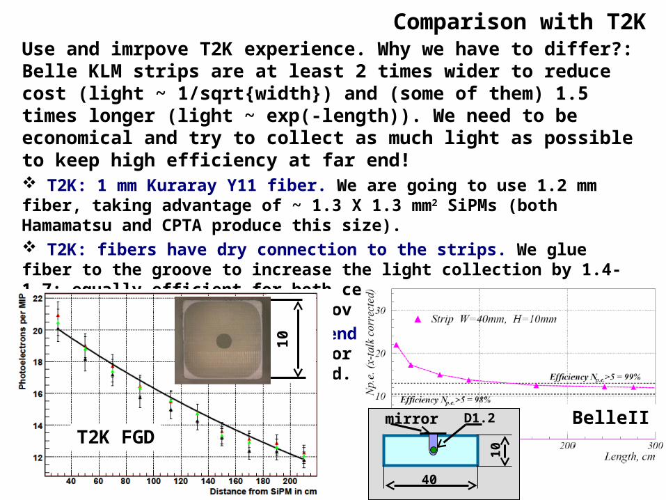
Comparison with T2K Use and imrpove T2K experience. Why we have to differ?: Belle KLM strips are at least 2 times wider to reduce cost (light ~ 1/sqrt{width}) and (some of them) 1.5 times longer (light ~ exp(-length)). We need to be economical and try to collect as much light as possible to keep high efficiency at far end! T2K: 1 mm Kuraray Y11 fiber. We are going to use 1.2 mm fiber, taking advantage of ~ 1.3 X 1.3 mm2 SiPMs (both Hamamatsu and CPTA produce this size). T2K: fibers have dry connection to the strips. We glue fiber to the groove to increase the light collection by 1.4-1.7: equally efficient for both central groove (Fermilab strips) and sawed groove (Kharkov strips). T2K aluminized the polished end and got ~70% mirroring efficiency. We glue the 3M mirror to the far end; this double the light yield from the far end.
T2K FGDBelleII
10
1040
D1.2mirror

Strips mass productionOperations, required to produce strip segment: Quality control of fibers (automatized with fiber rewind) Cuting fibers and polishing fiber ends (to be done simultaneoulsy for hundreds fibers); Glueing the mirror to the far end (experience of T2K group from INR, Moscow is useful); Glueing fiber inside the strip groove (experience from OPERA) Glueing the SiPM housing to the strip; Quality control of SiPMs (and database for 16k SiPMs); Glueing the SiPM to the housing and soldering to preamplifier; Glueing 15 strips into one segment (good for transportation, match with 16 channels electronics, 5 segments fit the existing iron gap size); Unlike T2K we do not use substrate because of different thermal expancion of polysterol and good materials for skin (G10, Al etc)
Estimated time and manpower: Strip production (12000 kg) 4 – 6 months. Fiber production (30 km) ?? (to be checked with Kuraray) SiPM production (16 k) ?? (to be checked with Hamamatsu and CPTA) Glueing: ~ 20 – 30 min/strip * 16 k = (3 – 5) man-years; Mounting segments to frame: 2 hours * 4 man/sector * 104 = 0.3 man-year pr
elim
inar
y
To be elaborated during full size prototype production (fall 2009)

Mechanical structure
The weight of one sector with RPC: Al frame 20 kg two Al covers 2 * 30 kg RPC 120 kg Plastic support str 40 kg Cables/strip masks etc 20 kg Total 250 kg
The weight of one sector with scintillator strips: Al frame 20 kg Scintillator 120 kg Support str 20 kg Cables etc 10 kg Total 170 kg
Al sector frame is required for transportation at B4, mounting/dismounting in iron gaps.The existing ones are obviously fit the gap well (and are not cheap): try to reuse them
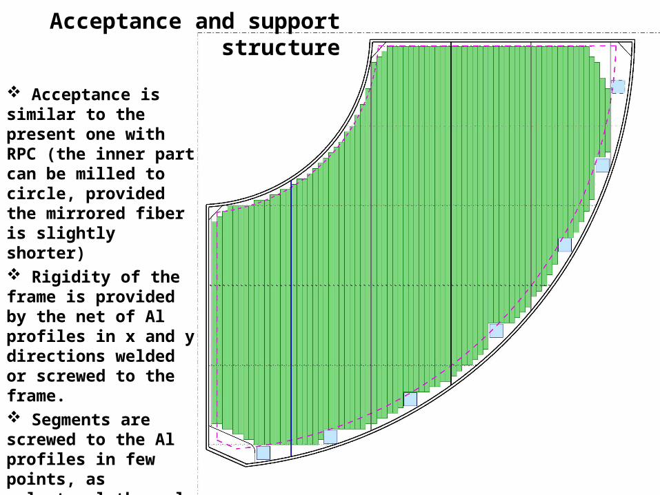
Acceptance and support structure
Acceptance is similar to the present one with RPC (the inner part can be milled to circle, provided the mirrored fiber is slightly shorter) Rigidity of the frame is provided by the net of Al profiles in x and y directions welded or screwed to the frame. Segments are screwed to the Al profiles in few points, as polysterol thermal expansion is much bigger than that of Al.
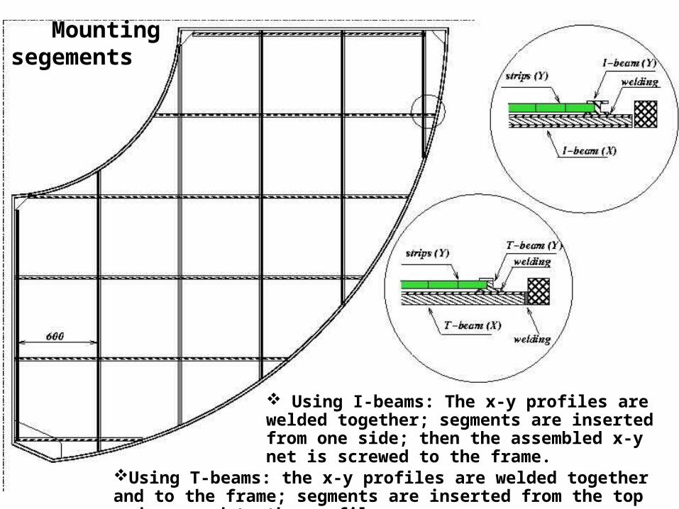
Mounting segements
Using T-beams: the x-y profiles are welded together and to the frame; segments are inserted from the top and screwed to the profiles
Using I-beams: The x-y profiles are welded together; segments are inserted from one side; then the assembled x-y net is screwed to the frame.

With the present configuration the installation is only possible when KEKB optics near IR is dismounted. Ineterference with time schedule for KEKB installation?No chance to repair?Can this be improved?
Sector installation, repair
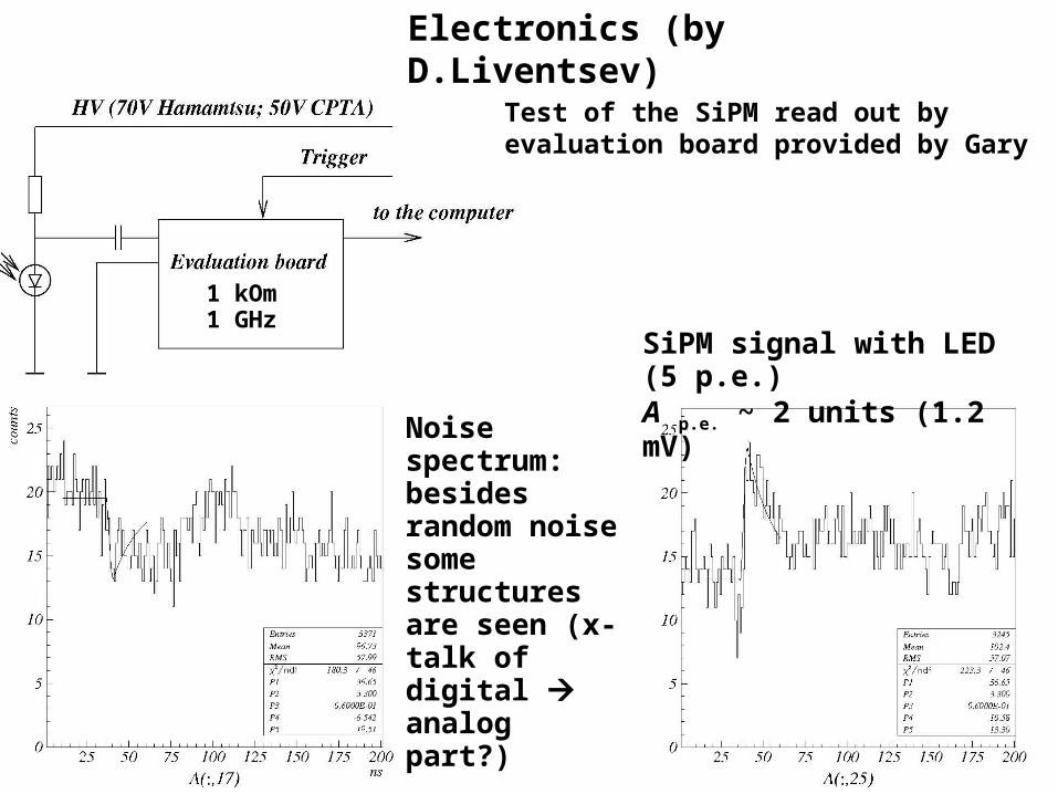
1 kOm 1 GHz
Noise spectrum:besides random noise some structures are seen (x-talk of digital analog part?)
SiPM signal with LED (5 p.e.) A p.e. ~ 2 units (1.2 mV)
Test of the SiPM read out by evaluation board provided by Gary
Electronics (by D.Liventsev)
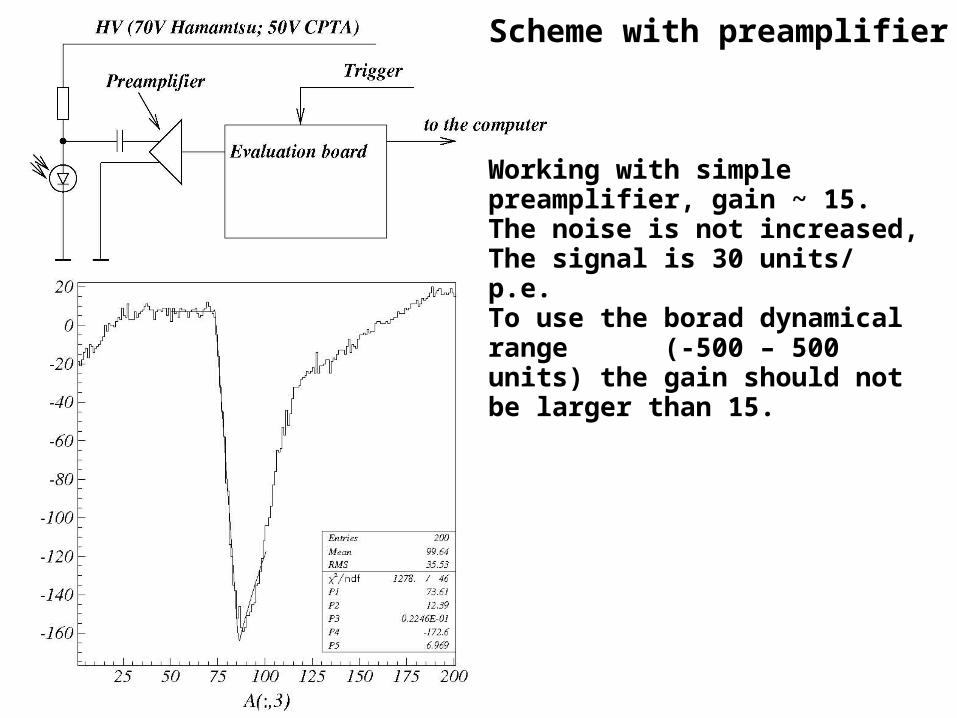
Working with simple preamplifier, gain ~ 15. The noise is not increased, The signal is 30 units/ p.e. To use the borad dynamical range (-500 – 500 units) the gain should not be larger than 15.
Scheme with preamplifier
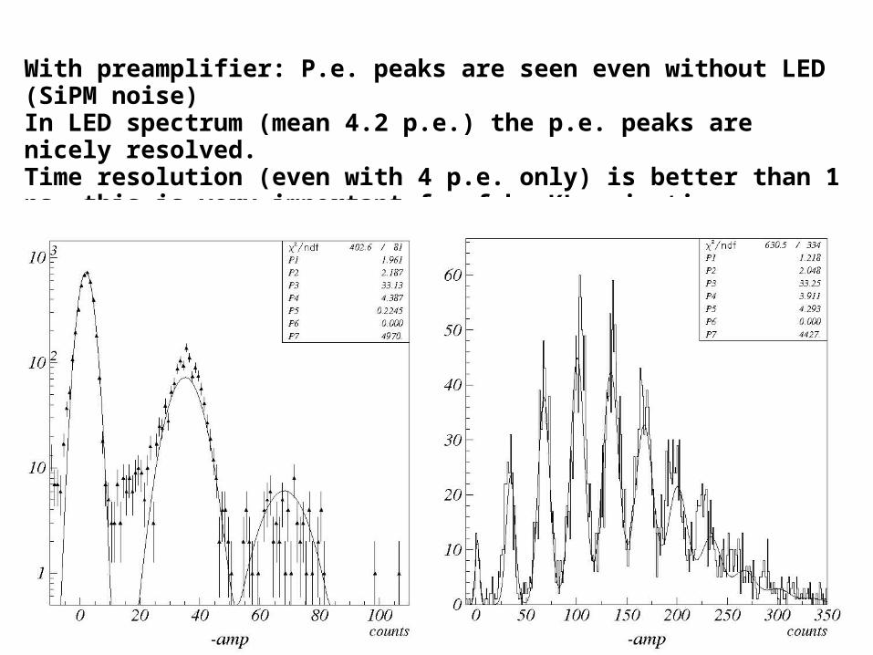
With preamplifier: P.e. peaks are seen even without LED (SiPM noise)In LED spectrum (mean 4.2 p.e.) the p.e. peaks are nicely resolved.Time resolution (even with 4 p.e. only) is better than 1 ns, this is very important for fake KL rejection + provide time of flight measurement for slow KL

Conclusion on electronics The universal read out board is appropriate for our tasks, However some
improvements are still required: either reduce the internal noise of the board (differential input should help a lot?) or(and) to amplifiy the SiPM signal
X-talks between channels are measured and consistent with Gary’s note ~ 2-5% (not a big problem, but it is better to reduce them)
HV ajustment is required. Can it be implemented in the read out board?
Can we place read out board to the iron gaps near SiPM: reliability, ageing? heating? optimization of geom. size?
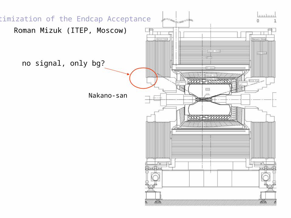
Optimization of the Endcap Acceptance
no signal, only bg?
Nakano-san
Roman Mizuk (ITEP, Moscow)

backward forward
K L
M
L A
Y E
R S
forward:full acceptance of all layers required
backward:layers 1-5: full acceptance (Rinner=130cm) 6-8: Rinner=150cm 9-12: 180cm more detailed optimization
should be done with Belle II MC
1
2
3
4
5
6
7
8
9
10
11
12
13
14
R (hit position), cm R (hit position), cm
Status for G4 simulation of scintillator KLM
Galina Pakhlova, ITEP
Many thanks to Leo and Hara san
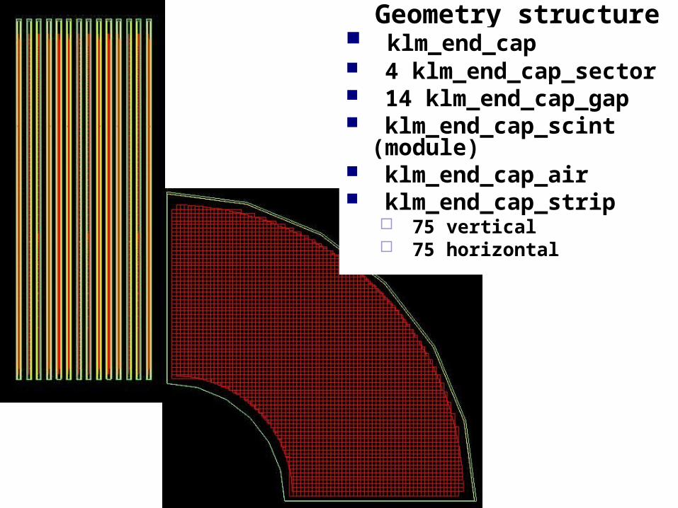
Geometry structure klm_end_cap 4 klm_end_cap_sector 14 klm_end_cap_gap klm_end_cap_scint (module)
klm_end_cap_air klm_end_cap_strip
75 vertical 75 horizontal
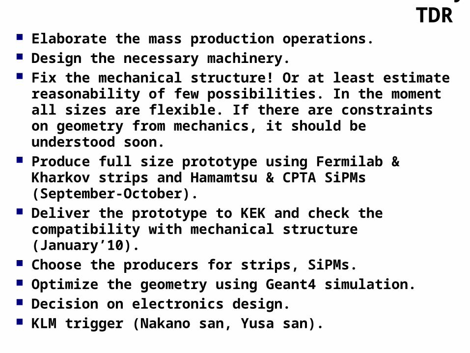
Plans by TDR Elaborate the mass production operations. Design the necessary machinery. Fix the mechanical structure! Or at least estimate
reasonability of few possibilities. In the moment all sizes are flexible. If there are constraints on geometry from mechanics, it should be understood soon.
Produce full size prototype using Fermilab & Kharkov strips and Hamamtsu & CPTA SiPMs (September-October).
Deliver the prototype to KEK and check the compatibility with mechanical structure (January’10).
Choose the producers for strips, SiPMs. Optimize the geometry using Geant4 simulation. Decision on electronics design. KLM trigger (Nakano san, Yusa san).


![v v }vod }( vPo] ZW }. ] v Ç · About iTEP International, the creators of iTEP The iTEP test has set a new standard for effi-ciency, accuracy, and flexibility. iTEP can be ... •](https://static.fdocuments.in/doc/165x107/5eb9d36294954e7d657929a2/v-v-vod-vpo-zw-v-about-itep-international-the-creators-of-itep-the.jpg)