KLIMA floorheating CABLE 2007
15
INSTALLATION INSTRUCTIONS (NEW BUILD ONLY) K L I M A ELECTRIC UNDERFLOOR HEATING CABLE
Transcript of KLIMA floorheating CABLE 2007
INSTALLATION INSTRUCTIONS (NEW BUILD ONLY)
KK LL II MM AAELECTRIC UNDERFLOOR HEATING CABLE

Dear Client,
Congratulations on the purchase of this KLIMA product. The KLIMA CABLE is manufacturedfrom high quality, durable materials. To guarantee that your product functions optimallythere are a few points of attention which are described in the Installation Instructions. Wecan only offer you the full guarantee if the KLIMA CABLE is correctly installed in accor-dance with the Installation Instructions. Carefully read the instructions prior to installation,do not forget the red centre page when doing so, and ensure that you have the correcttools and materials. The electrical installation must be carried out by a qualified electri-cian in accordance with IEE Regulations.If you have any questions or require more information then you can:
contact the Support Line Monday to Friday from 9 am to 5 pm:
0870 - 411 1115
or visit our website for more information and other products at:
WWW.KLIMA.CO.UK
© 01-2007 Klima Underfloor Heating Ltd, P.O. Box 2009, Aberfeldy, Perthshire, PH15 2WB
KLIMA CABLE INSTALLATION INSTRUCTIONS
2
1. CHECK:
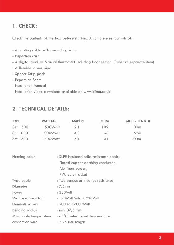
Check the contents of the box before starting. A complete set consists of:
- A heating cable with connecting wire - Inspection card- A digital clock or Manual thermostat including floor sensor (Order as separate item)- A flexible sensor pipe- Spacer Strip pack- Expansion Foam- Installation Manual- Installation video download available on www.klima.co.uk
2. TECHNICAL DETAILS:
TYPE WATTAGE AMPÉRE OHM METER LENGTH
Set 500 500Watt 2,1 109 30mSet 1000 1000Watt 4,3 53 59mSet 1700 1700Watt 7,4 31 100m
Heating cable : XLPE insulated solid resistance cable,Tinned copper earthing conductor,Aluminum screen,PVC outer jacket
Type cable : Two conductor / series resistanceDiameter : 7,5mmPower : 230VoltWattage pro mtr/l : 17 Watt/mtr. / 230VoltElements values : 500 to 1700 WattBending radius : min. 37,5 mmMax.cable temperature : 65°C outer jacket temperatureconnection wire : 2.25 mtr. length
3

3. POINTS OF ATTENTION:
The cable is insulated and watertight and can be installed on Foil finished insulation(Kingspan or Celotex) or existing concrete bases. The construction of the cable also allowsinstallation in wet spaces. The heating cable may never be installed under fixed objectslike wall units, kitchen units, baths, or showers and must be able to give off its warmthunimpeded.
The power supply must be disconnected during installation. All installations must be wiredthrough a suitably rated MCB or RCCD when applicable. All installations in wet areasmust be wired through a dedicated RCCD in line with the thermostat. All connections mustbe made by an approved Electrician in accordance with current IEE regulations.The electrical heating cable is patented worldwide and fully conforms to the EuropeanIEC 800 standards.
The cables capacity is 17W per meter at 230V. The invisible transition of the resistancecable (heating section of the cable) to the power cable (cold connection part of thecable) is indicated by the word "SPLICE" between two arrows. The 2 meter power cablemarked with stars: ******, may be extended.
THE HEATING CABLE CANNOT BE SHORTENED!!!! THE END SEAL CANNOT BE BROKEN!
This Klima Cable is a twin conductor (built in return cable) and has an extra aluminiumearth cladding to neutralise magnetic fields.
If multiple cables are installed in a space, they must be wired in parallel and a suitablyrated junction box may be incorporated so that only one power cable runs to the thermo-stat. Maximum capacity of the thermostat is 16 Amperes. If fitting more than one cableset and the combined area length exceeds 3400 watts, a suitably rated Contactor willhave to be fitted. The thermostat may only be installed by a qualified electrician.
The Klima Cable can be used under various floor finishes - Tile, Marble, Slate, Wood,Laminate, Vinyl and Carpet. (Tog rate of carpet and underlay should not exceed 2.5).If using underneath a wooden floor or carpet please contact your flooring supplier.
4
4. GUARANTEE:
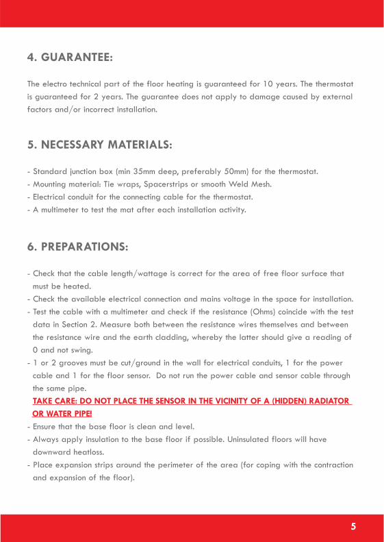
The electro technical part of the floor heating is guaranteed for 10 years. The thermostatis guaranteed for 2 years. The guarantee does not apply to damage caused by externalfactors and/or incorrect installation.
5. NECESSARY MATERIALS:
- Standard junction box (min 35mm deep, preferably 50mm) for the thermostat.- Mounting material: Tie wraps, Spacerstrips or smooth Weld Mesh.- Electrical conduit for the connecting cable for the thermostat.- A multimeter to test the mat after each installation activity.
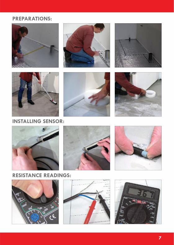
6. PREPARATIONS:
- Check that the cable length/wattage is correct for the area of free floor surface that must be heated.
- Check the available electrical connection and mains voltage in the space for installation.- Test the cable with a multimeter and check if the resistance (Ohms) coincide with the test
data in Section 2. Measure both between the resistance wires themselves and between the resistance wire and the earth cladding, whereby the latter should give a reading of0 and not swing.
- 1 or 2 grooves must be cut/ground in the wall for electrical conduits, 1 for the power cable and 1 for the floor sensor. Do not run the power cable and sensor cable through the same pipe.TAKE CARE: DO NOT PLACE THE SENSOR IN THE VICINITY OF A (HIDDEN) RADIATOR OR WATER PIPE!
- Ensure that the base floor is clean and level.- Always apply insulation to the base floor if possible. Uninsulated floors will have
downward heatloss.- Place expansion strips around the perimeter of the area (for coping with the contraction
and expansion of the floor).
5
7. CALCULATIONS FOR HEAT REQUIREMENTS:
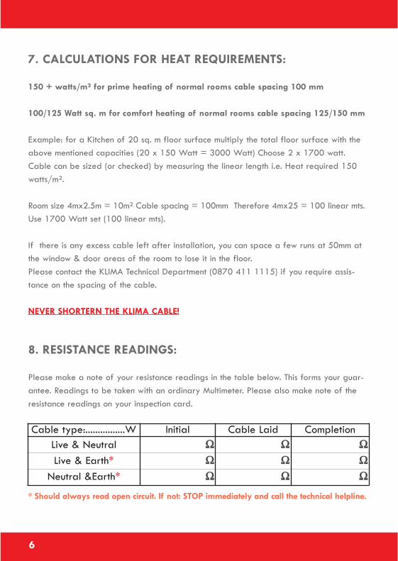
150 + watts/m² for prime heating of normal rooms cable spacing 100 mm
100/125 Watt sq. m for comfort heating of normal rooms cable spacing 125/150 mm
Example: for a Kitchen of 20 sq. m floor surface multiply the total floor surface with theabove mentioned capacities (20 x 150 Watt = 3000 Watt) Choose 2 x 1700 watt.Cable can be sized (or checked) by measuring the linear length i.e. Heat required 150watts/m².
Room size 4mx2.5m = 10m² Cable spacing = 100mm Therefore 4mx25 = 100 linear mts.Use 1700 Watt set (100 linear mts).
If there is any excess cable left after installation, you can space a few runs at 50mm atthe window & door areas of the room to lose it in the floor.Please contact the KLIMA Technical Department (0870 411 1115) if you require assis-tance on the spacing of the cable.
NEVER SHORTERN THE KLIMA CABLE!
8. RESISTANCE READINGS:
Please make a note of your resistance readings in the table below. This forms your guar-antee. Readings to be taken with an ordinary Multimeter. Please also make note of theresistance readings on your inspection card.
* Should always read open circuit. If not: STOP immediately and call the technical helpline.
6
Cable type:................W Initial Cable Laid CompletionLive & Neutral ΩΩ ΩΩ ΩΩLive & Earth* ΩΩ ΩΩ ΩΩ
Neutral &Earth* ΩΩ ΩΩ ΩΩ
7
PREPARATIONS:
INSTALLING SENSOR:
RESISTANCE READINGS:
8
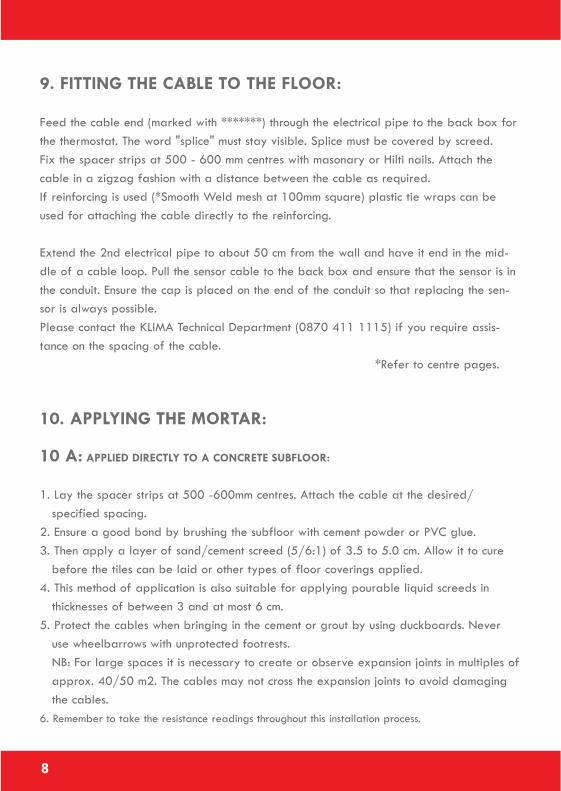
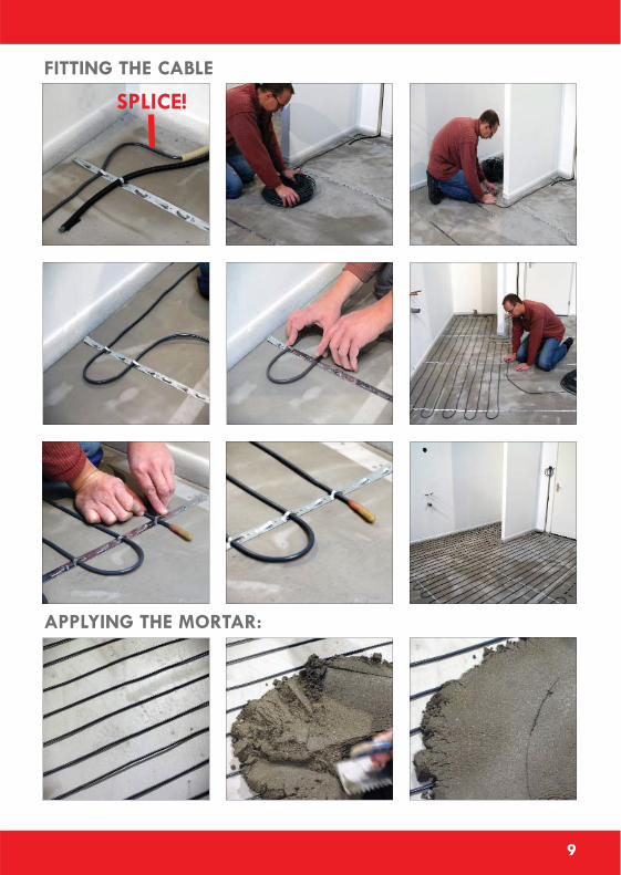
9. FITTING THE CABLE TO THE FLOOR:
Feed the cable end (marked with *******) through the electrical pipe to the back box forthe thermostat. The word "splice" must stay visible. Splice must be covered by screed.Fix the spacer strips at 500 - 600 mm centres with masonary or Hilti nails. Attach thecable in a zigzag fashion with a distance between the cable as required.If reinforcing is used (*Smooth Weld mesh at 100mm square) plastic tie wraps can beused for attaching the cable directly to the reinforcing.
Extend the 2nd electrical pipe to about 50 cm from the wall and have it end in the mid-dle of a cable loop. Pull the sensor cable to the back box and ensure that the sensor is inthe conduit. Ensure the cap is placed on the end of the conduit so that replacing the sen-sor is always possible.Please contact the KLIMA Technical Department (0870 411 1115) if you require assis-tance on the spacing of the cable.
*Refer to centre pages.
10. APPLYING THE MORTAR:
10 A: APPLIED DIRECTLY TO A CONCRETE SUBFLOOR:
1. Lay the spacer strips at 500 -600mm centres. Attach the cable at the desired/specified spacing.
2. Ensure a good bond by brushing the subfloor with cement powder or PVC glue.3. Then apply a layer of sand/cement screed (5/6:1) of 3.5 to 5.0 cm. Allow it to cure
before the tiles can be laid or other types of floor coverings applied.4. This method of application is also suitable for applying pourable liquid screeds in
thicknesses of between 3 and at most 6 cm.5. Protect the cables when bringing in the cement or grout by using duckboards. Never
use wheelbarrows with unprotected footrests.NB: For large spaces it is necessary to create or observe expansion joints in multiples ofapprox. 40/50 m2. The cables may not cross the expansion joints to avoid damaging the cables.
6. Remember to take the resistance readings throughout this installation process.
9
SPLICE!
FITTING THE CABLE
APPLYING THE MORTAR:
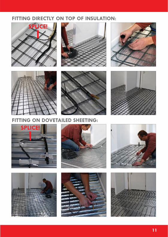
10 B: APPLIED DIRECTLY ON TOP OF INSULATION:
When laying the KLIMA CABLE onto the insulation the KLIMA CABLE must be laid andsecured onto a steel mesh. Do not install the cable directly onto the insulation. The cableis laid on to a smooth reinforcing mesh (approximately 100mm square), and secured withtie wraps. When using insulation, the top surface of the insulation must be aluminium cov-ered and coated appropriately to resist reaction with screed. Kingspan and Celotex man-ufacture insulation boards for the sole purpose of underfloor heating. The cable must notcome into contact with the insulation. Contact the insulation manufacturer for compatibilitywith cable floor heating systems and fitting instructions.The minimum depth of screed is 75mm. It is very important that the bedding is appliedfree of air bubbles. Air bubbles form insulating, non-conductive areas where the cablecannot release its heat and a danger of overheating arises which can cause damage tothe cable. To avoid this first of all wetter screed must initially be used to enclose thecable in the screed. Following this drier cement can be used for levelling the final bed-ding. In this case a pourable liquid screed is also a good option. Protect the cables whenbringing in the cement or grout by using duckboards. Never use wheelbarrows with unpro-tected footrests. Remember to take the resistance readings throughout this installationprocess and mark opposite.
10 C: ON DOVETAILED SHEETING:
Always allow for expansion. Dovetailed subfloors offer very poor insulation. It is recom-mended the dovetailed sheeting is insulated from below. Then fill in the grooves with mor-tar before installing the cables. Then install as indicated in Chapter 10A. In the latter casepourable liquid screed method can also be applied. Protect the cables when bringing inthe cement or grout by using duckboards. Never use wheelbarrows with unprotectedfootrests.
11. USING THE SYSTEM FOR THE FIRST TIME:
Depending on the drying time specified for the cement or grout, however not sooner than30 days after installation due to the natural expulsion of moisture from the floor. Turningon the system sooner can damage the floor.
10
11
SPLICE!
SPLICE!FITTING DIRECTLY ON TOP OF INSULATION:
FITTING ON DOVETAILED SHEETING:
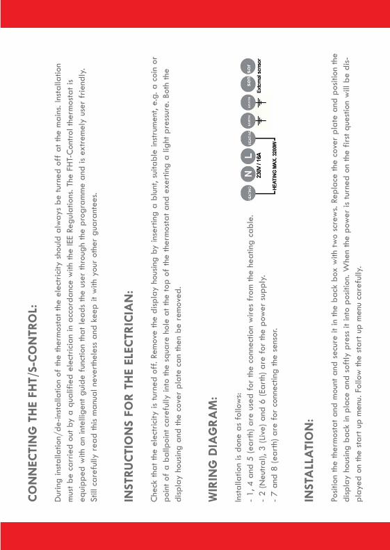
CO
NN
ECTI
NG
TH
E FH
T/S-
CO
NTR
OL:
Dur
ing
inst
alla
tion/
de-in
stal
latio
n of
the
ther
mos
tat t
he e
lect
ricity
sho
uld
alw
ays
be tu
rned
off
at th
e m
ains
.Ins
talla
tion
mus
t be
carr
ied
out b
y a
qual
ified
ele
ctric
ian
in a
ccor
danc
e w
ith th
e IE
E Re
gula
tions
.The
FH
T-C
ontro
l the
rmos
tat i
seq
uipp
ed w
ith a
n in
telli
gent
gui
de f
unct
ion
that
lead
s th
e us
er th
roug
h th
e pr
ogra
mm
e an
d is
extr
emel
y us
er f
riend
ly.
Still
car
eful
ly r
ead
this
man
ual n
ever
thel
ess
and
keep
it w
ith y
our
othe
r gu
aran
tees
.
INST
RUC
TIO
NS
FOR
TH
E EL
ECTR
ICIA
N:
Che
ck th
at th
e el
ectr
icity
is tu
rned
off
.Rem
ove
the
disp
lay
hous
ing
by in
sert
ing
a bl
unt,
suita
ble
inst
rum
ent,
e.g.
a co
in o
rpo
int o
fa
ballp
oint
car
eful
ly in
to th
e sq
uare
hol
e at
the
top
ofth
e th
erm
osta
t and
exe
rtin
g a
light
pre
ssur
e.Bo
th th
edi
spla
y ho
usin
g an
d th
e co
ver
plat
e ca
n th
en b
e re
mov
ed.
WIR
ING
DIA
GR
AM
:
Inst
alla
tion
is do
ne a
s fo
llow
s:-
1,4
and
5 (e
arth
) are
use
d fo
r th
e co
nnec
tion
wire
s fr
om th
e he
atin
g ca
ble.
- 2
(Neu
tral),
3 (L
ive)
and
6 (E
arth
) are
for
the
pow
er s
uppl
y.-
7 an
d 8
(ear
th) a
re f
or c
onne
ctin
g th
e se
nsor
.
INST
ALL
ATI
ON
:
Posit
ion
the
ther
mos
tat a
nd m
ount
and
sec
ure
it in
the
back
box
with
two
scre
ws.
Repl
ace
the
cove
r pl
ate
and
posit
ion
the
disp
lay
hous
ing
back
in p
lace
and
sof
tly p
ress
it in
to p
ositi
on.W
hen
the
pow
er is
turn
ed o
n th
e fir
st q
uest
ion
will
be
dis-
play
ed o
n th
e st
art u
p m
enu.
Follo
w th
e st
art u
p m
enu
care
fully
.
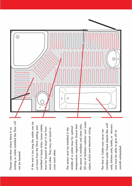
Plea
se n
ote
that
whe
re th
ere
is no
mat
ting
or c
able
inst
alle
d th
e flo
or w
illno
t be
heat
ed!
Ifth
e m
at is
too
long
the
cabl
e ca
n be
cut l
oose
fro
m th
e fib
re n
ettin
g an
din
stal
led
in lo
ose
strip
s.Lo
ose
cabl
esm
ust b
e lo
oped
at l
east
4 c
m f
rom
each
oth
er.T
hey
may
not
touc
h or
cros
s ea
ch o
ther
.
The
sens
or m
ust b
e in
stal
led
in th
em
iddl
e of
a ca
ble
loop
for
opt
imal
tem
pera
ture
reg
istra
tion.
Ensu
re th
atth
e se
nsor
is in
stal
led
wel
l cle
ar (m
in.
50 c
m) o
f(h
idde
n) r
adia
tor
and
wat
erpi
pes,
drai
ns a
nd e
lect
rical
wiri
ng.
The
Mat
or
Cab
le m
ay n
ever
be
inst
alle
d un
der
fixed
obj
ects
like
wal
lun
its,k
itche
n un
its,b
aths
,or
sho
wer
san
d m
ust b
e ab
le to
giv
e of
fits
war
mth
uni
mpe
ded.
PLEA
SE R
EAD
CA
REF
ULL
Y:IM
PORT
AN
T PO
INTS
OF
ATT
ENTI
ON
FRO
M T
HE
GEN
ERA
L IN
STA
LLA
TIO
N IN
STRU
CTI
ON
S
ALL
FLO
OR
S SH
OU
LD B
E IN
SULA
TED
BEF
OR
E U
ND
ERFL
OO
R H
EATI
NG
INST
ALL
ATI
ON
.
INST
ALL
ING
FLO
OR
HEA
TIN
G:
KLIM
A C
ABL
E:Th
e co
nnec
ting
cabl
e C
AN
NO
T be
sho
rten
ed.T
he p
art o
fth
e ca
ble
with
the
wor
d **
SPLI
CE*
** m
ust b
ein
stal
led
in th
e flo
or s
cree
d.
Shor
teni
ng th
e co
nnec
ting
cabl
e fo
r th
e KL
IMA
MAT
:The
con
nect
ing
cabl
e m
ay b
e sh
orte
ned
AT M
OST
by
3 m
eter
s (n
ole
ss th
an 2
met
ers)
.All
cabl
es th
at a
re a
ttach
ed to
the
mat
mus
t be
inst
alle
d in
the
floor
.
Exte
ndin
g co
nnec
ting
cabl
es:T
he c
onne
ctin
g ca
bles
can
be
exte
nded
as
requ
ired.
Take
how
ever
the
capa
city
(Am
ps) o
fth
e flo
or h
eatin
g in
to a
ccou
nt a
nd a
djus
t the
cap
acity
of
the
exte
nsio
n ca
bles
acc
ordi
ngly
.
FLO
OR
SEN
SOR
INST
ALL
ATI
ON
:
Ensu
re th
at th
e se
nsor
is in
stal
led
wel
l cle
ar (m
in.5
0 cm
) of
cent
ral h
eatin
g pi
pes,
wat
er p
ipes
,dra
ins
and
elec
tric
alw
iring
.Ins
tall
the
sens
or a
s cl
osel
y as
pos
sible
in th
e m
iddl
e of
2 lo
ops.
Ensu
re th
at th
e he
atin
g ca
bles
do
not m
ake
dire
ctco
ntac
t with
the
cond
uit i
n w
hich
the
floor
sen
sor
is m
ount
ed.T
he e
nd o
fth
e se
nsor
pip
e m
ust b
e cl
osed
.Che
ck th
at th
ese
nsor
cab
le is
fre
e to
mov
e to
the
end
ofth
e pi
pe.
Exte
ndin
g th
e flo
or s
enso
r:Th
e flo
or s
enso
r m
ay b
e ex
tend
ed a
s re
quire
d up
to a
max
imum
of
10 m
eter
s.U
se a
sig
nal

gy
qp
gca
ble
for
exte
ndin
g th
e se
nsor
.Ens
ure
that
the
sens
or c
an a
lway
s be
rep
lace
d in
cas
e it
fails
.The
sim
ples
t way
of
doin
gso
is in
stal
ling
a hi
dden
junc
tion
box
in w
hich
the
signa
l cab
le is
con
nect
ed to
the
sens
or.
INST
ALL
ING
KLI
MA
CA
BLE
ON
WEL
D M
ESH
:
Ifus
ing
a po
rous
flo
or f
inish
suc
h as
lim
esto
ne e
tc.o
n to
p of
the
scre
ed,w
e re
com
men
d th
at th
e w
eld
mes
h is
galv
anise
dot
herw
ise th
e ru
st o
ffth
e m
esh
can
rise
to th
e to
p of
your
fin
ished
flo
or s
urfa
ce d
urin
g tim
e.
USI
NG
TH
E FL
OO
R H
EATI
NG
FO
R T
HE
FIR
ST T
IME:
Allo
w th
e flo
or s
uffic
ient
dry
ing
time
befo
re y
ou tu
rn o
n th
e flo
or h
eatin
g.Fo
r til
ed f
loor
s a
dryi
ng ti
me
of3/
4 w
eeks
afte
r in
stal
latio
n sh
ould
gen
eral
ly b
e ob
serv
ed.C
onsu
lt th
e su
pplie
r/m
anuf
actu
rer
rega
rdin
g th
e ap
plic
able
dry
ing
time
for
the
prod
uct.
For
sand
/cem
ent s
cree
d flo
ors
a dr
ying
tim
e of
1 w
eek
per
appl
ied
cm w
ith a
min
imum
of
4-5
wee
ks is
gene
rally
obs
erve
d.on
sult
the
supp
lier/
man
ufac
ture
r re
gard
ing
the
appl
icab
le d
ryin
g tim
e fo
r yo
ur s
ituat
ion.
AD
JUST
ING
TH
E TH
ERM
OST
AT:
Tim
er f
unct
ion:
Ifyo
u ha
ve a
ther
mos
tat w
ith a
tim
er f
unct
ion
and
wan
t to
use
it to
set
the
floor
dry
ing
time
mak
e su
re y
ouse
t a lo
w c
omfo
rt te
mpe
ratu
re.(
15°C
for
exa
mpl
e).W
hen
the
ther
mos
tat a
utom
atic
ally
goe
s on
(aft
er th
e re
quire
d dr
y-in
g tim
e) th
en th
e co
mfo
rt te
mpe
ratu
re m
ay b
e slo
wly
rai
sed
(1°C
per
day
) unt
il th
e de
sired
com
fort
tem
pera
ture
isre
ache
d.
Oth
er th
erm
osta
t / s
ettin
gs:I
fyo
u ha
ve a
diff
eren
t the
rmos
tat o
r if
you
do n
ot w
ant t
o us
e th
e tim
er f
unct
ion
ensu
re th
atyo
u th
en s
et th
e co
mfo
rt te
mpe
ratu
re lo
w (1
5°C
for
exa
mpl
e).A
fter
taki
ng th
e re
quire
d dr
ying
tim
e in
to a
ccou
nt y
ou c
anth
en m
anua
lly r
aise
the
floor
tem
pera
ture
with
app
rox.
1°C
per
day
unt
il th
e de
sired
com
fort
tem
pera
ture
is r
each
ed.