Klaus Union GmbH & Co. KG PUMP SERIES SLM AVP ... SER VICE KU-Logo für farbigen HG Klaus Union GmbH...
6
Klaus Union GmbH & Co. KG Blumenfeldstr. 18 44795 Bochum Germany KU_AVP_E_07/14 Phone +49 234 45 95 - 0 Fax +49 234 45 95 - 7000 E-Mail info@klaus-union.com Internet www.klaus-union.com PUMP SERIES SLM AVP ACCORDING TO API 685 SEALLESS WITH MAGNET DRIVE Product Program Pumps: Pumps with Magnet Drive E Centrifugal Pumps acc. to DIN EN ISO 2858 & DIN EN ISO 15783, SLM NV E Centrifugal Pumps acc. to ANSI B73.3, SLM AVO E Centrifugal Pumps for Petrochemical Applications acc. to API 685, SLM AVP E Centrifugal Pumps for High Pressure Applications, SLM SV / SLM GV E Centrifugal Pumps for High Temperature Applications, SLM NHO E Centrifugal Pumps for Liquids Containing Solids, SLM NV OT E Self-Priming Centrifugal Pumps, SLM SV E Multistage Centrifugal Pumps, Tension-Rod or Barrel-Type Design, SLM GV E Submerged Centrifugal Pumps, SLM NVT E Double-Suction Centrifugal Pumps, SLM ZV Pumps with Shaft Sealing E Twin Screw Pumps, DSP E Centrifugal Pumps acc. to DIN EN ISO 2858 & DIN EN ISO 5199, NOV E Multistage Centrifugal Pumps, Tension-Rod or Barrel-Type Design, GOV / GOVT E Horizontal and Vertical Propeller Pumps, P E Bottom-Flange Propeller Pumps, UP E Submerged Centrifugal Pumps, TP NO E Double Suction Centrifugal Pumps, NZ Product Program Valves: E Globe Valves, T E Globe Valves, Y E Gate Valves, Isomorphous Construction Series E Gate Valves, Wedge or Wedge Plates E Relief Valves E Check Valves E Sight Glasses E Strainers E Filters E Bottom Valves E Safety Valves Klaus Union Service Performance: E Workshop / On-Site Repairs E Genuine Spare Part Delivery Worldwide E Spare Parts Storage E Customized Spare Parts Management E On-Site Maintenance E Installation E Retrofitting E On-Site Testing / Monitoring E Customer Advisory Service E Start Up & Commissioning E Individual 24 / 7-Service E Trouble-Shooting E In-House & On-Site Training E On-Site Assembly and Disassembly E Long-Term Maintenance Contracts E Maintenance Planning and Consulting E Diagnostics
Transcript of Klaus Union GmbH & Co. KG PUMP SERIES SLM AVP ... SER VICE KU-Logo für farbigen HG Klaus Union GmbH...

SERV ICE
S E R V I C E
KU-Logo für farbigen HG
Klaus Union GmbH & Co. KG
Blumenfeldstr. 1844795 BochumGermany
KU_A
VP_E
_07/
14
Phone +49 234 45 95 - 0Fax +49 234 45 95 - 7000
E-Mail [email protected] www.klaus-union.com
PUMP SERIES SLM AVPACCORDING TO API 685 SEALLESS WITH MAGNET DRIVE
Product Program Pumps:
Pumps with Magnet Drive
E Centrifugal Pumps acc. to DIN EN ISO 2858 & DIN EN ISO 15783, SLM NV
E Centrifugal Pumps acc. to ANSI B73.3, SLM AVOE Centrifugal Pumps for Petrochemical Applications
acc. to API 685, SLM AVPE Centrifugal Pumps for High Pressure
Applications, SLM SV / SLM GVE Centrifugal Pumps for High
Temperature Applications, SLM NHOE Centrifugal Pumps for Liquids
Containing Solids, SLM NV OTE Self-Priming Centrifugal Pumps, SLM SVE Multistage Centrifugal Pumps,
Tension-Rod or Barrel-Type Design, SLM GVE Submerged Centrifugal Pumps, SLM NVTE Double-Suction Centrifugal Pumps, SLM ZV
Pumps with Shaft Sealing
E Twin Screw Pumps, DSPE Centrifugal Pumps acc. to DIN EN ISO 2858 &
DIN EN ISO 5199, NOVE Multistage Centrifugal Pumps,
Tension-Rod or Barrel-Type Design, GOV / GOVTE Horizontal and Vertical Propeller Pumps, PE Bottom-Flange Propeller Pumps, UPE Submerged Centrifugal Pumps, TP NOE Double Suction Centrifugal Pumps, NZ
Product Program Valves:
E Globe Valves, TE Globe Valves, YE Gate Valves, Isomorphous Construction SeriesE Gate Valves, Wedge or Wedge PlatesE Relief ValvesE Check ValvesE Sight GlassesE StrainersE FiltersE Bottom ValvesE Safety Valves
Klaus Union Service Performance:
E Workshop / On-Site RepairsE Genuine Spare Part Delivery WorldwideE Spare Parts StorageE Customized Spare Parts ManagementE On-Site MaintenanceE InstallationE RetrofittingE On-Site Testing / MonitoringE Customer Advisory ServiceE Start Up & CommissioningE Individual 24 / 7-ServiceE Trouble-ShootingE In-House & On-Site TrainingE On-Site Assembly and DisassemblyE Long-Term Maintenance ContractsE Maintenance Planning and ConsultingE Diagnostics
2
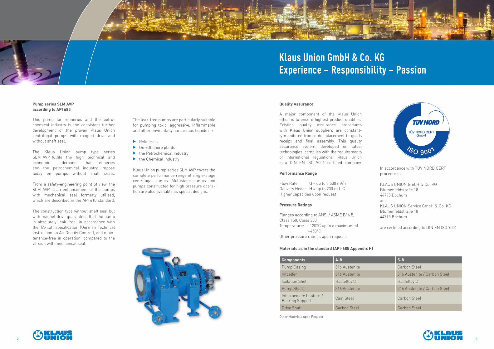
The leak-free pumps are particularly suitable for pumping toxic, aggressive, inflammable and other environtally harzardous liquids in:
E RefineriesE On-/Offshore plantsE the Petrochemical IndustryE the Chemical Industry
Klaus Union pump series SLM AVP covers the complete performance range of single-stage centrifugal pumps. Multistage pumps and pumps constructed for high pressure opera-tion are also available as special designs.
Pump series SLM AVP according to API 685
This pump for refineries and the petro-chemical industry is the consistent further development of the proven Klaus Union centrifugal pumps with magnet drive and without shaft seal.
The Klaus Union pump type series SLM AVP fulfils the high technical and economic demands that refineries and the petrochemical industry impose today on pumps without shaft seals. From a safety-engineering point of view, the SLM AVP is an enhancement of the pumps with mechanical seal formerly utilised, which are described in the API 610 standard. The construction type without shaft seal but with magnet drive guarantees that the pump is absolutely leak free, in accordance with the TA-Luft specification (German Technical Instruction on Air Quality Control), and main-tenance-free in operation, compared to the version with mechanical seal.
3
Klaus Union GmbH & Co. KG Experience – Responsibility – Passion
Quality Assurance
A major component of the Klaus Union ethos is to ensure highest product qualities. Existing quality assurance procedures with Klaus Union suppliers are constant-ly monitored from order placement to goods receipt and final assembly. This quality assurance system, developed on latest technologies, complies with the requirements of international regulations. Klaus Union is a DIN EN ISO 9001 certified company. Performance Range
Flow Rate: Q = up to 3,500 m³/h Delivery Head: H = up to 200 m L.C. Higher capacities upon request Pressure Ratings
Flanges according to ANSI / ASME B16.5, Class 150, Class 300 Temperature: -120°C up to a maximum of +450°C Other pressure ratings upon request.
Components A-8 S-8Pump Casing 316 Austenite Carbon Steel
Impeller 316 Austenite 316 Austenite / Carbon Steel
Isolation Shell Hastelloy C Hastelloy C
Pump Shaft 316 Austenite 316 Austenite / Carbon Steel
Intermediate Lantern / Bearing Support Cast Steel Carbon Steel
Drive Shaft Carbon Steel Carbon Steel
Other Materials upon Request
Materials as in the standard (API-685 Appendix H)
In accordance with TÜV NORD CERT procedures, KLAUS UNION GmbH & Co. KGBlumenfeldstraße 18 44795 Bochum and KLAUS UNION Service GmbH & Co. KG Blumenfeldstraße 18 44795 Bochum are certified according to DIN EN ISO 9001

Design Details SLM AVP
1. Casing Drain (API-§ 6.3.3)With Flange
2. Journal Bearing (API-§ 6.9)Double Bearing made of Silicon Carbide (SSiC); counter centred Combination for Universal Utilisation
3. Thrust Bearing (API-§ 6.9)Hydraulic mesures reduce Axial Thrust over the complete Performance Range
4. Wear Rings (API-§ 6.6)Replaceable on the Impeller and in the Casing
5. Gasket (API- § 6.2.7)On the Isolation Shell placed in Shunt
6. Inner Magnet Carrier (API-§ 9.1.3.3)With additional Mechanical Rub Ring
7. Intermediate Lantern (API-§ 9.1.3.3/9.1.3.5)With Magnet Drive Rub Ring and Assembly / Disassembly Guidance
8. Flushing System (API-§ 6.1.9)Pressurized over the entire Operating Range
9. Thermal BarrierLowers the Anti-Friction Bearing Temperature and thus increases the Working Life of the Anti-Friction Bearings
10. Bearing Support (API-§ 9.1.4)Oil Lubrication with Labyrinth Sealing 11. Secondary Sealing (API-§ 3.66/3.68)Single Isolation Shell with Leakage Monitoring and Drain (Secondary Control System) Optional: Double Isolation Shell with Pressure Monitoring (Secondary Containment System) 12. Casing and Intermediate Lantern (API-§ 6.2.9)Centerline Support
4 5

Journal Bearings (API-§ 6.9)
The thrust and radial journal bearings are self-lubricated and in the standard design consist of pure sintered silicon carbide (SSiC). The journal bearings components are fixed and secured in both the axial and radial directions. Compensation for the different thermal expansion coefficients of the metallic and ceramic components is ensured by the constructional design. The pressurised flush flow for lubration and cooling of the journal bearings is taken from a high pressure location in the hydraulic system and fed directly into the journal bearings (see Fig. 1)
Magnet Drive (API-§ 9.1.3./6.1.9)
The magnet drive is configured concentri-cally and transmits torque without slip via the field of the permanent magnets. The thermally stable samarium-cobalt material (Sm2Co17) withstands operating tempera-tures of up to 400°C. The magnetic material aluminium-nickel-cobalt (AlNiCo) is utili-sed for higher temperatures of up to 450°C. A second pressurised flush flow is taken off at a high pressure location in the hydraulic system and fed to the magnet drive, where it provides for the necessary heat dissipation. The pressurised flush flow ensures that the temperature rise in the isolation shell area does not lead to evaporation of the pumped liquid (see Fig. 2).
6 7
SLM AVP – The Modular System forSealless Centrifugal Pumps
Pump Casing
The design of pump casing has been calcula-ted with the help of the finite element method (FEM) for 50 bar maximum internal pressure at 120°C and a nozzle load corresponding to double the values specified in API 685. The corrosion allowance of 3 mm stipulated according to § 6.2.5 has been taken into consideration. The flange connections are designed according to ANSI/ASME B16.5, Class 300.
8.816e+02 2.000e+02 1.743e+02 1.486e+02 1.229e+02 9.714e+01 7.143e+01 4.571e+01 2.000e+01 2.313e+01
8.816e+02 2.000e+02 1.743e+02 1.486e+02 1.229e+02 9.714e+01 7.143e+01 4.571e+01 2.000e+01 2.313e+01
Von Mises Tension (Maximum) Averaged Values Original Models Combination Principal Units (mmNs)
12
3
4
56
0
7
1
2 35
0
7
4
6
Fig. 1. Pressure / Temperature Profile / Journal Bearing Flush Flow
Fig. 2. Pressure / Temperature Profile / Isolation Shell Flush Flow
1
2
3
4
5
6
6
7
1
2
3
4
5
7
1
0,9
0,8
0,7
0,6
0,5
0,4
0,3
0,2
0,1
0
Vapour Pressure Curve
Vapour Pressure Curve
Temperature (°C)
Temperature (°C)
0
0
Liquid
Vapour
Pres
sure
/ Di
ffere
ntia
l Pre
ssur
e [-
]
1
0,9
0,8
0,7
0,6
0,5
0,4
0,3
0,2
0,1
0
Pres
sure
/ Di
ffere
ntia
l Pre
ssur
e [-
]
Liquid
Vapour

Protection and Safety are of Utmost Importance
8 9
Outer Magnet Carrier Protection (API-§ 9.1.3.5) and Rubring Zones (API-§ 9.1.3.3)
To protect the isolation shell, rubring zones are provided on both the outer magnet carrier and the inner magnet carrier. In the event of a deflection of the magnet rotors, this ef-fectively avoids contact of the rotors with the isolation shell to avoid damaging the shell. The mounting zone in the intermediate lantern ensures that the outer magnet carrier is safely guided during assembly and disassembly. This prevents accidental damage to the outer magnet carrier. By virtue of this design, the outer magnet carrier sheathing requested by API 685 is not required.
Klaus Union Standard: Single Isolation Shell with Leakage Monitoring and Drain at the Intermediate Lantern (API-§ 3.68)
The standard version of the SLM AVP pump is equipped with a single isolation shell. The intermediate lantern is equipped with a labyrinth system to the atmosphere, a leakage monitoring system and a drain connection. A pressure gauge or a liquid sen-sor can be utilized as a leakage monitor. The labyrinth seal upstream of the anti-friction bearings serves as a throttling point in the event of isolation shell damage leading to product escaping into the intermediate lantern. The pressure rise or the presence of liquid is detected by the monitoring system. This design corresponds to the secondary control system described in API 685 (§ 3.68).
Optional: Double Isolation Shell with Pres-sure Monitoring (API-§ 3.66)
In this version, the pressure-containing second (outer) isolation shell serves as secondary containment and thus fulfils the API definition of the secondary containment system according to § 3.66.The outer isolation shell is arranged concen-trically around the inner isolation shell. The pressure is monitored in the cavity between the two containment shells and is configured with a pressure below atmosphere in the state of the pump as delivered. It is thus possible to detect isolation shell damage from outside and from inside. In the event of damage from outside, the pressure monitor will indicate atmospheric pressure; whereas in the event of damage from inside, the sys-tem pressure will be indicated.
Drive Unit with Secondary Control System Double Isolation Shell as Secondary Containment System Disassembling the Outer Magnet Carrier Tube with Rubring Zones and Stud Bolts with Lifting Lug

Performance Curves SLM AVP
30002000100050104,4 20 30 100 300200 500 5000 8800 17600
80604010 15 302085 6421 3
10
25
100
200
400
492
150
75
50
30
80
100
150
60
50
40
20
15
8
6
5100 300 500 2000 40001000200150
16x14x15
8x6x20
12x10x20
14x12x20
16x14x20
3x1.5x13
14x12x15
12x10x15
(1200 rpm)16x16x20
6x4x13
2x1x10
3x1.5x10
3x1.5x63x2x6
3x2x13
10x8x20
6x4x10
6x4x8
4x3x13
10x8x15
10x8x13
4x3x8
4x3x10
8x6x15
8x6x13
8x6x10
1.5x1x6
1.5x1x8
3x1.5x8
3x2x8
3x2x10
Head
[ m
]
Head
[ ft
]
1750 1/min
Flowrate
Flowrate
[ m3/h ]
[ usgpm ]
600
26401000 1500 2000300 75050040020080604010 154,4 20 25 30 100 150
604020 30 5010 15875 6421 310
50
807060
100
150
125
200
300
400
600
500
700
820
350
250
175
30
9080
100
120
250
140
180200225
160
6070
50
40
20
35
25
15
80 100 150 400300200
2x1x10
3x1.5x63x2x6
6x4x13
6x4x10
6x4x8
4x3x13
4x3x10
3x2x13
3x2x10
3x2x8
3x1.5x13
3x1.5x10
4x3x8
1.5x1x6
1.5x1x5
1.5x1x83x1.5x8
Head
[ m
]
Head
[ ft
]
3500 1/min
Flowrate
Flowrate
[ m3/h ]
[ usgpm ]
500
22001000 1500300 80060040020080604010 154,4 20 25 30 100 150
604020 30 5010 158 975 6421 310
50
80
70
60
100
160
140
120
200
300
400450492
350
250
180
30
9080
100110
150
130
60
70
50
4045
20
35
25
15
12
80 100 150 400300200
2x1x10
3x1.5x63x2x6
6x4x13
6x4x10
6x4x8
4x3x13
4x3x10
3x2x13
3x2x10
3x2x8
3x1.5x13
3x1.5x10
4x3x8
1.5x1x6
1.5x1x5
1.5x1x83x1.5x8
Head
[ m
]
Head
[ ft
]
2900 1/min
Flowrate
Flowrate
[ m3/h ]
[ usgpm ]
5000
220001000030002000100050104,4 20 30 100 300200 500 5000
80604010 15 302085 6421 3
2
3
4
1012
5
10
15
30
20
100
200
328
250
150
80
5060
40
30
80100
605040
2025
15
8
65
100 300 500 300020001000200150
8x6x20
6x4x13
4x3x8
4x3x10
4x3x13
1.5x1x6
1.5x1x8
2x1x10
3x1.5x6
3x1.5x8
3x1.5x10
3x1.5x13
3x2x8
3x2x10
3x2x13
3x2x6
10x8x2014x12x2012x10x20
16x14x15
14x12x15
12x10x1510x8x15
10x8x13
16x14x20
(1000 rpm)16x16x20
8x6x15
8x6x10
8x6x13
6x4x8
6x4x10
Flowrate
Flowrate
[ m3/h ]
[ usgpm ]
Head
[ m
]
Head
[ ft
]
1450 1/min
Performance Curve 60 Hz 3500 min-1
Performance Curve 60 Hz 1750 min-1
Performance Curve 50 Hz 2900 min-1
Performance Curve 50 Hz 1450 min-1
10 11