KISSsoft & KISSsys Gear Design · PDF fileWith integrated KISSsoft calculation modules ......
28
KISSsoft & KISSsys Gear Design Software www.KISSsoft.ch
Transcript of KISSsoft & KISSsys Gear Design · PDF fileWith integrated KISSsoft calculation modules ......

KISSsoft & KISSsys
Gear Design Software
www.KISSsoft.ch

2 of 28
Jiri Dolejs, SEW Eurodrive CZ, Czech Republic: “The calculation program KISSsoft has been used in SEW Eurodrive CZ company since 2004 on two seats of node locked licenses. Thanks to the modular structure of KISSsoft and wide variety of calculation modules, it is possible to assemble a tool for technical calculations tailored exactly according to user‘s needs, alternatively according to customer‘s needs. In case of necessity, it is possible to add another compatible module. Since the beginning of our usage of this software, KISSsoft has undergone many changes. New functions are added on regular base and the current functions are improved.
Sonja Goris, ZF Wind Power Antwerp NV, Belgium: „As a leading wind power drive manufacturer, we are delighted to work with KISSsoft. We use the KISSsoft software on an ongoing basis, along with other software suites, when developing our drives for wind power units in the 1.5 to 6+ MW range. We particularly appreciate the range of functions provided by KISSsoft, and its user-friendly interface, which means that the variant and certification calculations are performed in a clear and easy to understand manner. “
Tomasz Wróblewski, FLSmidth MAAG Gear Sp. z.o.o., Poland : „We are a large gear manufacturing company. The KISSsoft and KISSsys calculation software suites are an essential part of our business and are used together with our own specialized in-house toothing software programs. We use KISSsoft‘s highly efficient sizing functions to size the toothings. KISSsoft can even handle the calculations involved in shaft and bearing calculations for use in heavy industry. “
Edwin C. Hahlbeck, Powertrain Eingeers Inc., Wisconsin, USA: „As you know, we have been early users of KISSsoft programs here in the USA. As consultants engaged in gearbox design for energy, mining, industrial, telescopes, turbo equipment and other applications we are using your software most every day. It is solid and dependable, broad in scope, integrated well and continuously improving. At our firm we use all the gear rating programs, shaft analysis and bearing design extensively. The fit analysis is also very important with calculation of micro-slippage and added bonus. The software has incredible depth and flexibility. It’s obvious to me that it comes from experienced engineers who have been there and done that. We have used it in submittals for review by API, DNV and GL without ever a question related to this product. We have found the support for problems or questions to be exceptional, and handled well by staff that quickly interprets our needs, typically on first communication. We recommend this product for static analysis for anyone engaged in mechanical design, without reservation. “

3 of 28
KISSsoft worldwide History Started as in house software with Kissling AG
gear company KISSsoft AG founded in 1998 KISSsoft LLC, US, founded in 2005 EES KISSsoft GmbH, founded 2008 KISSsoft China Pvt Ltd, founded 2012 KISSsoft software has been commercially
available for the last 27 years About 2600 commercial installations
worldwide About 150 educational installations worldwide
Main office KISSsoft AG, Switzerland www.KISSsoft.ch
US branch KISSsoft LLC, USA www.KISSsoft.com
China branch KISSsoft China Pvt. Ltd., China www.KISSsoft.com.cn
General distributor Asia EES KISSsoft GmbH, Switzerland www.EES-KISSsoft.ch
Sales and support partners Estudio Pina, Argentina CETIM, France Stadler Antriebstechnik, Germany Mr. Saltini, Italy Mega Makina, Turkey Kadkraft Systems, India STech&H, Korea
Consultancy and engineering Provided through EES KISSsoft GmbH Contact [email protected] Specialised in wind gearboxes, industrial
gearboxes and slewing bearings Design, engineering analysis and testing

4 of 28
Applications Fine pitch, plastic and sintered gearing White and brown ware Gearheads Automotive actuators Medical and research Powertools …
Energy generation Turbo gears Wind energy, main gearboxes Generator shafts Engine gear trains Pitch and yaw drives …
Aerospace Rovers, satellites Helicopter transmission Turbine PTO Flap actuators, UAV …
Industrial General purpose and heavy duty gearboxes Mining and raw materials Cranes and winches Vertical roller mill gearbox Steel mill gearboxes Servomotors, geared motors Robotics, spindle drives Material handling Open gears …
Vehicle applications Automotive, LCV transmissions Trucks and busses Tractors, harvesters Motorbikes and three wheelers Motorsport Military vehicles, armoured vehicles Locomotives, trams, cableways Construction vehicles, forklifts …
And many more…

5 of 28
Training Form Public trainings in German, Korean, French,
Italian, Spanish or English language Company specific trainings At KISSsoft AG training centre
Topics KISSsoft & KISSsys software usage KISSsys programming Gear theory, gear design technology Fine pitch gearing
Trainers Mechanical engineers with strong engineering
background Long time software users or programmers
Maintenance and support (AMC) Services Software updates Patches Installation support Software support (software usage) Technical support (software application)
Types Perpetual (by service contract) Annual renewal
Software modules Combination of modules Basic modules for gearing, shafts, connections Expert modules as add-on modules Total of about 50 modules
Adding modules Modules may be added to an existing licence
Complete list of modules Request through reseller or directly from EES
KISSsoft GmbH

6 of 28
Modules General KISSsoft modules can be run independently KISSsys module requires KISSsoft CAD modules require KISSsoft
KISSsoft Cylindrical gears, rack & pinion, bevel and
hypoid gears, worm gears, face gears, crossed axis helical gears, non-circular gears
Shafts and roller bearings, hydrodynamic bearings, shaft systems, bearing stress
Shaft-hub connections High strength bolted connections Spring analysis, chains and belts Tolerance stack up, local stress analysis,
Hertzian contact stress, spindles KISSsys Readymade gearbox models for helical
gearboxes, bevel-helical gearboxes, worm-helical gearboxes and planetary systems
Machine element library to build own models Programming language module Let’s you build virtually any gearing system
CAD Accurate, manufacturing simulation based 3D
geometry of gears 2D CAD export in neutral format or graphical
format 3D export to CAD systems (gear geometry)
Databases General Database is user editable and can be
transferred from one release to next Includes copy past functions
Materials General material database Specific materials for gears, shafts, springs
Bearings FAG/INA, SKF, Koyo, NSK, Timken For standard bearing data and bearing inner
geometry (only through user input)

7 of 28
KISSsys, systems module
KISSsys software combines kinematic analysis, lifetime calculation, 3D graphics, user defined tables and dialogs with a programming language. It is the tool of choice for strength and lifetime analysis of various kinds of drive trains and gearboxes. KISSsys lets the user do quick yet detailed parametric studies of a complete power train in very little time to compare different variants of a concept or to analyse a given design for different loads. In KISSsys, all parts (gears, shafts, bearings, connections) of the gearbox are linked and the strength/lifetime analysis is performed simultaneously for all elements. A three dimensional graphical presentation of the current state of the system immediately shows the geometrical influence of every change in parameters. This approach greatly accelerates the design process and results in a much more balanced design even during the concept phase. The machine elements calculated range from gears, shafts, bearings, shaft-hub connections to bolts. This will result in a more balanced starting design and fewer modifications will be necessary further down in the design process to reach an optimised design. Furthermore, documentation of the calculation is simplified and all calculation data for a whole drive train or gearbox is stored in a single file. KISSsys uses KISSsoft for the strength and lifetime calculations of the various machine elements. KISSsys features: Kinematics Calculation: Power flow / speed with spur, bevel, worms
and face gear stages, Modelling of rotational mechanisms
(planetary, Ravigneaux, Wolfrom,…), Differentials, (with bevel or spur gears), chain
and belt transmissions, Couplings can be activated and deactivated,
slippage taken into account

8 of 28
Integrated strength and lifetime calculation: With integrated KISSsoft calculation modules System deflection is considered in tooth
contact analysis
Machine element library: Spur/helical gear pair Planetary gears, compound planetary gears Bevel and hypoid gears Worm gears, crossed axis helical gears Face gears Shaft-bearing systems Shaft-hub connections Synchronizer
3D-models: Automatic 3D-display (based on the data
defined in KISSsoft), 3D-model export to CAD platforms, gearbox
housing import, (-step / -iges), Collision check with imported CAD geometry
Special features: Calculations with load spectra for all machine
elements in the model Integrated programming language for
implementation of special functions Animation of gear movement Cut view and deformed systems Wizards, libraries and toolboxes for quick
modelling KISSsys is used e.g. to Analyse wind turbine gearboxes again and
again for different loading conditions Ensure that the design of a plastic gear set for
an automotive actuator fits into a given design space
Calculate power flow in CVT transmission Maintain a database of geared motor gears Estimate the manufacturing cost of a gearbox
even during the design phase Optimise bearing lifetime by variation of the
gears positions on a shaft Create specific reports e.g. for certification And many more …

9 of 28
GPK module GPK module is a set of readymade KISSsys models. The models are provided to the customers as a library to be used in KISSsys. The models made available cover the most typical industrial gearboxes. The models feature advance level functions to accelerate the design process of standard industrial gearboxes. The need for the user to build his own models is eliminated and detailed reporting functions further reduce the time to document the design. Automatic sizing functions for the gears, bearings and shafts result in a well balanced gearbox. Price calculations based on user defined cost per mass data allow for constant control over gearbox costs. Types of gearboxes Helical gearboxes Bevel, helical-bevel gearboxes Worm, worm helical gearboxes Planetary gearboxes
Configurations One, two, three, four or five stage helical
gearboxes, with or without roller bearings One bevel without, with one, two or three
helical stages, all with roller bearings One worm without, with one, two or three
helical stages, all with roller bearings Functions Sizing of gear stages (distribution of ratio
among the stages, sizing for given centre distance)
Sizing of shafts and bearings (based on stress levels and required bearing life)
Cost estimation (considering bearings, shafts and gears)
Report generation (summary, pricing and detailed report)
Detailed gear, bearing and shaft design through KISSsoft
Free arrangement of shafts in space External forces on input and output shaft Settings for lubrication, temperature,
orientation of gearbox in space, materials, calculation methods and graphics

10 of 28
Helical gear basis modules Configurations Spur or helical gear, herringbone gear,
considering face width offset Grease or oil lubricated or dry running gears Metallic or plastic gears Involute or non-involute gears Any number of teeth, any type of tooth
height, internal or external gears Gear geometry calculation Gear geometry along ISO21771 Reference profile along ISO53.2, DIN867, JIS,
BS5482 or own input Tolerances along DIN3967, ISO1328, own
input or for theoretical gearing Centre distance along ISO286, ISO7168,
DIN58405 or own input Gear quality along ISO1328, AGMA2015-1-
A01, DIN3961, DIN3961, DIN3963, DIN23961, DIN23962, DIN23963, AGMA200-A88
Gear rating DIN3990 method B, DIN3990 method B with
YF along method C, DIN3990 Part 41 (vehicles) method B
ISO6336:2006, ISO6336:2006 with corrigendum 2007
Static rating against yield AGMA2001-B88, AGMA2001-C95, AGMA2001-
D04, AGMA2101-D04 metric AGMA6004-F88, AGMA6014-A06, AGMA6011-
I03 Plastic gears along Niemann, VDI2545,
VDI2545 modified, VDI2736 As FVA software for DIN3990 BV/Rina FREMM3.1, Rina 2010, DNV41.2 For nominal load or load spectrum
Report listing For default report or user specific template Tooth geometry and material Tooth root strength, tooth flank strength Tooth scuffing, micropitting and wear Tooth thickness dimensions, tooth tolerances Modifications, manufacturing Additional data

11 of 28
Cylindrical gear general modules Gear geometry calculation Calculation based on gear or tool reference
profile Calculation based on true tool geometry Calculation based on mating gear geometry Import and export of gear or tool geometry
from CAD system Calculation of theoretical, acceptance and
operating backlash for metallic and plastic gears and housings
Load spectrum calculation Direct input of load spectrum or import from
text or Excel file Up to 300 load steps in spectrum Calculation of lifetime based on required
safety factor, safety factors based on required lifetime and permissible torque based on required safety factor and lifetime
Calculation of partial damages For DIN3990, ISO6336 and AGMA2001
AGMA925 calculations Calculation of scuffing safety Calculation of contact stress, lubricant film
thickness Micropitting calculation Micropitting rating along ISOTR 15144 Specific lubricant film thickness calculation
along AGMA925 Lubricant film thickness calculation along
ISOTR 15144 based on true contact stress Additional reports Gear data for drawings Manufacturing tolerances along ISO1328-1,
ISO1328-2, DIN3961, DIN23961, AGMA2015-1, AGMA200, BS436-2
Proposal for hardness depth along Niemann, AGMA2101, ISO6336
User specific reports based on templates Master gear calculation Calculation of master gear geometry Meshing of master gear with gear

12 of 28
Helical gear sizing modules Configurations Sizing functions to find optimised gears (in
terms of mass, power density, stiffness, space requirements)
Functions to reverse engineer gears Functions to optimise gear properties
Rough sizing Proposal of several gear solutions for required
power rating, required ratio, given material Considers gear quality, permissible ratio error For single load level or load spectrum With standard reference profile
Fine sizing Define permissible ranges for module,
pressure angle, helix angle, centre distance and profile shift
Define target ratio and permissible deviation Define maximum number of solutions Set maximum permissible tip diameter and
minimum permissible root diameter For pre-defined number of teeth or varying
number of teeth Different filter and sorting functions Display solutions in table or in graphical form Report with assessment of solutions for
different criteria Centre distance sizing Sizing from gear pair data Sizing for target profile shift sum
Sizing of profile shift For balanced specific sliding To avoid pointed tooth or undercut For turbo gears For maximised strength on flank or root or
maximised scuffing strength Sizing of tooth height / reference profile Sizing of reference profile for target
transverse contact ratio Sizing of maximum possible root radius
Sizing of profile and lead corrections Sizing of tip and root relief for different
shapes Sizing of end relief and crowning Automatic search for optimum corrections

13 of 28
Helical gear modifications Configurations Considers all modifications in profile and lead
direction Calculation based on up to 41 gear sections Pitch errors may be considered in part or fully Calculation for nominal or operating centre
distance Calculation for nominal or partial load level Meshing friction considered in calculation Considers true gear geometry from
manufacturing simulation Output Calculation of load distribution in profile and
lead direction True stress levels compared to stress levels
calculated along standards (ISO/DIN/AGMA) True root stress calculation Calculation of YS and YF along full tooth root Considering true root geometry from
manufacturing Root geometry optimisation for minimised
root stresses Calculation along ISO/TR 15144 Calculation of specific lubricant film thickness
along g ISO/TR 15144
Considering true contact stress, temperature in contact, surface roughness and lubricant properties
Calculation of micropitting safety, method A and B
Lead and profile modifications End relief (left and right end) Crowning Helix angle modification Linear and progressive tip/root modification Profile crowning (barrelling) Pressure angle modification Tip chamfer or rounding Grinding disk plunge depth Graphical output in involute diagram Flank twist Triangular end relief (left and right end)
14 of 28
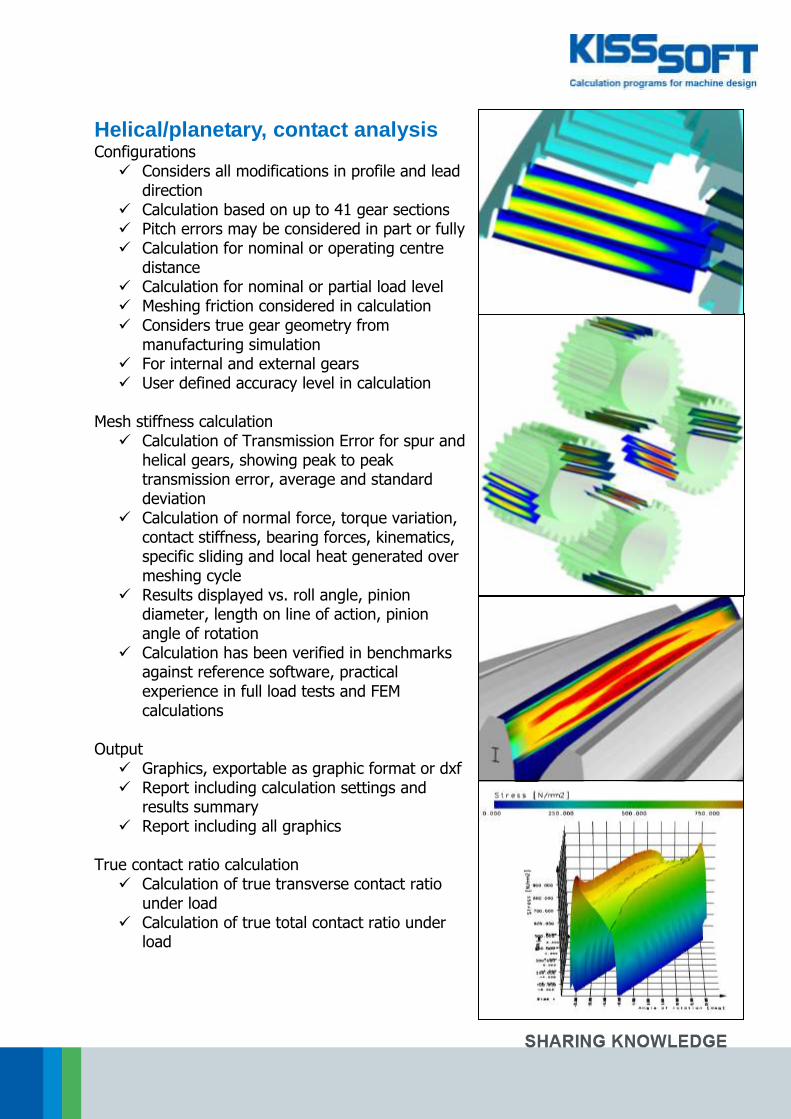
Helical/planetary, contact analysis Configurations Considers all modifications in profile and lead
direction Calculation based on up to 41 gear sections Pitch errors may be considered in part or fully Calculation for nominal or operating centre
distance Calculation for nominal or partial load level Meshing friction considered in calculation Considers true gear geometry from
manufacturing simulation For internal and external gears User defined accuracy level in calculation
Mesh stiffness calculation Calculation of Transmission Error for spur and
helical gears, showing peak to peak transmission error, average and standard deviation
Calculation of normal force, torque variation, contact stiffness, bearing forces, kinematics, specific sliding and local heat generated over meshing cycle
Results displayed vs. roll angle, pinion diameter, length on line of action, pinion angle of rotation
Calculation has been verified in benchmarks against reference software, practical experience in full load tests and FEM calculations
Output Graphics, exportable as graphic format or dxf Report including calculation settings and
results summary Report including all graphics
True contact ratio calculation Calculation of true transverse contact ratio
under load Calculation of true total contact ratio under
load

15 of 28
Planetary, herringbone, idlers General, planets Based on helical gear calculation modules Calculation of planet pin location for non-
evenly spaced planets Influence of rim thickness of ring gear and
planet gears considered Assembly check Sizing function for load distribution factor
along AGMA6123 Rough and fine sizing function
Strength rating, planets Along ISO6336, DIN3990, AGMA2001,
AGMA6004, BV/Rina FREMM3.1 for metallic gears
Along VDI2545 and Niemann for plastic gears Calculation of ring gear strength along
VDI2737 Calculation of alternating bending factor for
planet root General, idler gears, herringbone gears Based on helical gear calculation modules For one or two idler gears Load input on first, output on last gear
Worm gear modules General For ZC, ZI, ZA, ZN, ZK, ZH geometry Includes rough and fine sizing function Accurate 3D geometry
Strength rating Along E DIN3996:2005, DIN3996:1998,
ISO/DIS14521.2:2006, AGMA6034, AGMA6135
No load contact analysis System data Considers drive direction, bearing power loss,
seal loss, permissible wear Considers cooling through housing and
lubricant and running time

16 of 28
Bevel gear modules General Strength rating for nominal load or load
spectrum Database for reference profile and tolerances Different geometry configurations with
uniform tooth depth, constant slot width, modified slot width, different root and tip apex positions
For spur, helical or spiral bevel gears Rough and fine sizing function Calculation of measurement grid for
Klingelnberg, Gleason or Wenzel gear tester Strength rating Strength rating along ISO10300, Method B
and C, DIN3991, AGMA2003, CN3028/KN3030 for Cyclo-Palloid gears and along KN3025/KN3030 for Palloid gears
Hypoid gear calculation along KN3029/KN3030 for Cyclo-Palloid gears, KN3026 for Palloid gears, ISO10300
Plastic gear rating along VDI2545 or Niemann Static strength rating and rating of differential
planetary gears, efficiency along Wech Flank breakage calculation along Annast
Manufacturing For face hobbed or face milled gears Considering Klingelnberg machine list Accurate 3D gear geometry for CNC
machining No load tooth contact analysis considering
lead and profile modifications
Rack and pinion modules For spur or helical arrangement Strength rating Along ISO6336, DIN3990, AGMA2001,
AGMA6004, BV/Rina FREMM3.1 for metallic gears and VDI2545 and Niemann for plastic
Output Reports for manufacturing tolerances,
drawing data, hardness depth proposal

17 of 28
Crossed axis helical gear modules General Strength rating along ISO6336 (modified
along Niemann), along Hoechst for worm gears and along Hirn for worm gears
Calculation of theoretical backlash, acceptance and operating backlash
Calculation of flank, root and scuffing safety factor with single load or load spectrum
Output of control measures like dimension over pins and balls
With rough and fine sizing function Configurations For plastic and metallic materials Calculation with lead or helix angle Calculation of meshing efficiency For worm type or helical gear type mesh (any
helix angle) Tooth form calculation with modifications like
tip and root relief, chamfer, tip rounding, elliptic root rounding for improved noise and strength properties
Face gear modules General Strength rating along ISO6336 (modified
along Niemann, Roth and Basstein), ASS/Crown Gear/DIN3990, based on ISO10300, based on DIN3991
For 90deg or other shaft angle, with axis offset, for spur and helical gears
Configurations Crown gear with cylindrical pinion as spur or
helical gear Calculation of crown gear geometry at
different diameters by simulating manufacturing with a pinion type cutter
Check against undercut and pointed tooth by varying tooth height
Export of 2D or 3D geometry considering tolerances
Crowning of face gear through modifications on pinion type cutter
Output of contact lines on face gear

18 of 28
Non circular gears Non circular gears can be calculated in KISSsoft based on an operating pitch curve. Gears may be closed or open. Note that this module is available to customers as a package if combined with a joint project in order to ensure that the software does meet the customer requirements. Design of geometry: required momentary ratio may be defined required meshing curve may be defined
From there, the following is calculated calculation of meshing curve from momentary
ratio calculation of shaping cutter from gear/tooth
data calculation of backlash such that no jamming
occurs calculation of non-circular gear contour export to CAD with different levels of accuracy
(up to 800 points per flank) add tip rounding modify root geometry to increase strength check of meshing / collisions in 2D calculation of position of rolls for dimension
over rolls measuring
Beveloid gears Beveloid gears (conical gears) can be modelled and rated in KISSsoft for small shaft and cone angles Cone angle on both gears may be different Considers shaft and cone angles Spur and helical gears Includes microgeometry model Strength rating as per DIN, ISO, AGMA based
on equivalent cylindrical gear No load tooth contact analysis

19 of 28
Shaft modules General Graphical shaft editor for fast modelling Add features to shaft to define stress
concentrations Add force elements like gears, pulleys or
couplings for simple load definition Material and lubricant database Search function for critical cross sections
Configurations Single shaft or shaft systems Combined with multiple roller bearings Different materials from database or own
input Linear or non-linear calculation with Euler or
Timoshenko beam model considering temperature effects
Strength rating Strength rating along DIN743, FKM guideline
or Hänchen & Decker For static and fatigue strength, for single load
case or load spectrum Using material database or own definition for
S-N curve Automatic recognition and calculation of
stress concentrations Buckling, natural frequencies Calculation of combined bending and torsion
natural frequencies and natural modes Considers bearing stiffness
Deformation and stiffness calculation Non-linear bearing stiffness is considered
based on inner bearing geometry Up to eight concentric shafts may be modelled
with connections Any number of loads may be added
Tooth trace calculation Calculation of shaft deformation of pinion
shaft, calculation of necessary lead correction Housing stiffness, bearing stiffness and shaft
stiffness may be considered

20 of 28
Bearing modules Configuration Calculation of single bearing or bearing-shaft
system With single load or load spectrum Sizing function for bearing selection Statically over-determined shaft systems,
paired bearings Bearing life rating Basic rating using load capacity numbers Modified rating considering lubricant
properties Reference rating considering load distribution Modified reference rating Along ISO281, ISO/TS16281, ISO76
Bearing stiffness Based on bearing inner geometry Shaft-bearing interaction for shaft and bearing
systems Considers clearance/pre-tension Considers bearing, shaft, hub tolerances
Load distribution calculation Load distribution among rolling elements Contact stresses for balls Contact stresses for rollers, considering roller
geometry modification (logarithmic) Thermal rating Along DIN732
Bearing database Bearing data from different bearing suppliers For different bearing types Database for basic bearing properties Database for bearing inner geometry, user
editable Separate database for lubricants, lubricant
purity definitions along ISO4406 Hydrodynamic bearings Axial bearings according to DIN31653 Radial bearings along DIN31654, Niemann
and Spiegel (for grease lubricated bearings)

21 of 28
Shaft-hub connections modules Cylindrical interference fit Strength rating along DIN7190 Sizing function for tolerances Stress calculation for stepped hub and hollow
shaft Considers torsional, radial and bending load,
including centrifugal loads Calculation of mounting temperatures
Conical interference fit For different mounting procedures Calculation along Kollmann Considers cone angle and cone angle
tolerances Key Geometry along DIN6885, ANSIB17.1 Strength rating along DIN6892 Woodruff key
Involute spline Geometry along DIN5480, ISO4156, ANSIB92,
own definition Tolerances along DIN5480, ISO4156,
ANSIB92, own definition Reference profiles along DIN5480, ISO4156,
ANSIB92, own definition Strength rating along Niemann or DIN5466 Graphical output
Straight sided spline Geometry along DIN5464, DIN5471,
DIN5472, ISO14, own definition Strength rating along Niemann Graphical output
Serrated spline Geometry along DIN5481 Strength rating along Niemann
Polygons 3-sided and 4-sided polygon along DIN32711,
DIN32711 Strength rating along Niemann

22 of 28
High strength bolting modules Bolt rating along VDI2230, configurations Connection under axial load only Connection under axial and shear load Flange type bolted connection Arbitrary bolting pattern Import of FEM results for loading condition
Bolt, nut and washer types Own bolt geometry definitions Own nut and washer definition Washers: ISO7089, ISO7090, ISO7093,
ISO940 Nut: ISO274, ISO4032, ISO4035, ISO8673,
ISO8675 Bolt: ISO4762, ISO4014, ISO4017, ISO1207,
ISO8765, ISO8676, … Strength classes, 8.8, 10.9, 12.9, A1…A5, own
definition Tightening Considers different tightening procedures Considers pre-tension loss Considers friction in thread and under
head/nut Temperatures For low and high temperatures Considers assembly temperature, temperature
of bolt and temperature of clamped parts
Shear pins, circlips Calculation along Niemann / Seeger, configurations Bolt under shearing Cross pin under torque Longitudinal pin under torque Pin under bending Shear pin system Hub and shaft circlip
Calculations Static or fatigue loads For full or notched type pins Material database Sizing function for pin diameter

23 of 28
Springs modules Compression springs Geometry along DIN2098 or own definition Tolerances along DIN2095 or DIN2096 Calculation along EN 13906-1
Tensile springs Different end geometries Tolerances along DIN2097 or DIN2096 Calculation along EN13906-2
Garter springs Tolerances along DIN2194 Calculation along EN13906-3
Spring disks Geometry along DI2093 or own definition Calculation along DIN2092
Torsional spring Different head forms Single or multiple springs Calculation along 2091
General purpose modules Hertzian contact Contact between balls, cylinders, ellipsoid and
plane Calculation of contact ellipse dimension Calculation of contact stress and sub-surface
stress Local stress analysis Strength verification along FKM guideline For steel and aluminium For 1, 2 and 3 dimensional stress state
Tolerance analysis Min/Max values, statistical calculation Standardised or user defined tolerances
Belt drives, chain drives Chain sprocket geometry Belt and chain length Belt and chain strength

24 of 28
CAD interfaces KISSsoft offers the following CAD interfaces:
Thus, at the pressing of a button, the gears defined in KISSsoft can be exported to any of the above mentioned CAD platforms. Gear Geometries supported are indicated above. A gear can be generated for an existing construction or, simply, as a new part. Gears are generated by polylines, circular arc approximation or splines. The exact tooth profile is generated by manufacturing simulation considering tools like shaping cutter or protuberance hob. In addition, it is possible to place several gears on shafts already modelled in the CAD environment. Neutral interfaces in 2D and 3D formats complete the CAD-specific export functions.

25 of 28
Export to FEM Supported formats 3D, step 3D, sat 2D, dxf
Import of Single parts Multiple parts
Automatic import into most FEM pre-processors. Mesh seeds on part or edges or global mesh size definition depending on pre-processor used Parts may be partitioned for control of mesh density in different regions of the gear or tooth Imported geometry includes profile and lead modifications, root geometry simulated from manufacturing, inner diameter, tip chamfer or rounding Imported geometry may be based on upper, mean and lower Tooth thickness tolerance Tip diameter tolerance
Accuracy is better than 0.1um

26 of 28
Export to CAM KISSsoft includes a highly accurate and a highly detailed modeller for 3D gear geometries. Based on the geometry generated in KISSsoft, mould cavities, electrodes or final parts may be machined using 5 axis CNC machines. For most gears, the 3D models can be generated including a protuberance to facilitate a roughing and a final machining operating. Gears or cavities successfully machined by our customers include Spur, helical and herringbone gears Spur, helical and spiral bevel gears Bevel gears with constant or varying tooth
height Spur and helical face gears Worm gears (different shapes)
Geometries may be imported into any CAM software. Imported geometry includes profile and lead modifications, root geometry simulated from manufacturing, inner diameter, tip chamfer or rounding. Accuracy is better than 0.1um. Tests have confirmed that contact patterns of e.g. spiral bevel gears are matching with predictions calculated in KISSsoft. Request specific information and technical papers on the subject from your local agent. Gear geometry measurement may be controlled using KISSsoft measuring data (flank and root coordinates on measurement grid) and point normal vectors exported in different formats (e.g. to suit Klingelnberg, Gleason or Wenzel gear testers).

27 of 28
Licensing Types of licenses Single user license protected by USB dongle
(hardware locked) Single or multi user network license (with
license on server) Installation Hardware locked license: software is installed
and run on PC Floating license: software can be installed on
server or on clients Operating system Windows (XP or later) 32 or 64 bit systems
Documentation, publications Downloadable documents from www.EES-KISSsoft.ch/download White papers and application reports KISSsoft and KISSsys tutorials List of software modules Screenshots of software
Documentation Manual, 1100 pages Tutorials, about 120 pages
Languages Tutorials available in German, English, French,
Italian and Chinese
Contact details General distributor, Asia
Mr. Hanspeter Dinner
[email protected] EES KISSsoft GmbH
Hauptstr. 7 6313 Menzingen
Switzerland
India office
Mr. Raman Gupta
[email protected] Kadkraft Systems Pvt. Ltd.
SCO 196-197, 1st Floor Sector 34-A, Chandigarh
India
Korea office
Dr. Young Il Kwon [email protected]
STech&H Co. Ltd.
#301 Moonhang bld, 44-17, Samsung-dong Kangnam-gu, Seoul
Korea
China office
Mrs. Nancy Su [email protected]
KISSsoft China Pvt. Ltd.
Suzhou SIP China

28 of 28
EES KISSsoft GmbH Hauptstrasse 7 P.O. Box 121
6313 Menzingen Switzerland
++41 41 755 33 20