
KISSsoft 03/2015 Tutorial 2 - Calculation programs for ... · PDF fileKISSsoft 03/2015 –...
12
KISSsoft 03/2015 – Tutorial 2 Cylindrical interference fit KISSsoft AG Rosengartenstrasse 4 8608 Bubikon Switzerland Tel: +41 55 254 20 50 Fax: +41 55 254 20 51 [email protected] www.KISSsoft.AG
Transcript of KISSsoft 03/2015 Tutorial 2 - Calculation programs for ... · PDF fileKISSsoft 03/2015 –...
KISSsoft 03/2015 – Tutorial 2
Cylindrical interference fit
KISSsoft AG
Rosengartenstrasse 4
8608 Bubikon
Switzerland
Tel: +41 55 254 20 50
Fax: +41 55 254 20 51
www.KISSsoft.AG

09.02.2015 2 / 12
Contents
1 Starting KISSsoft ...................................................................................................................................... 3 1.1 Selecting a calculation .................................................................................................................... 3
2 Calculating a cylindrical interference fit .................................................................................................... 4 2.1 Task ................................................................................................................................................ 4 2.2 Sizing a tolerance pair .................................................................................................................... 5 2.3 Running the analysis and report ..................................................................................................... 5 2.4 Further analysis options and settings ............................................................................................. 8
2.4.1 Settings ...................................................................................................................................... 8 2.4.2 Calculate the maximum permissible nominal torque .................................................................. 9 2.4.3 Hub with varying outer diameters ............................................................................................. 10 2.4.4 Defining your own tolerances ................................................................................................... 11 2.4.5 Influence of temperature .......................................................................................................... 11 2.4.6 Additional loads ........................................................................................................................ 12
09.02.2015 3 / 12
1 Starting KISSsoft
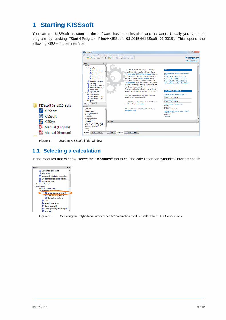
You can call KISSsoft as soon as the software has been installed and activated. Usually you start the
program by clicking "StartProgram FilesKISSsoft 03-2015KISSsoft 03-2015". This opens the
following KISSsoft user interface:
Figure 1. Starting KISSsoft, initial window
1.1 Selecting a calculation
In the modules tree window, select the "Modules" tab to call the calculation for cylindrical interference fit:
Figure 2. Selecting the "Cylindrical interference fit" calculation module under Shaft-Hub-Connections

09.02.2015 4 / 12
2 Calculating a cylindrical interference fit
2.1 Task
To size a cylindrical interference fit using the following data to ensure no sliding occurs.
Diameter of joint 60 mm
Length of Interference fit 50 mm
Outer diameter, Hub 90 mm
Shaft bore 10 mm
Nominal torque 400 Nm
Axial force 200 N
Speed 10'000 1/min
Coefficient of friction 0.12
Service temperature 20 °C
Application factor 1.25
Material shaft 34CrNiMo6
Material Hub C60
Shaft surface quality N6
Hub surface quality N6
Enter this data as follows:
Figure 3. Input window - inputting the known data
The first step is to define a suitable tolerance pair.
09.02.2015 5 / 12
2.2 Sizing a tolerance pair
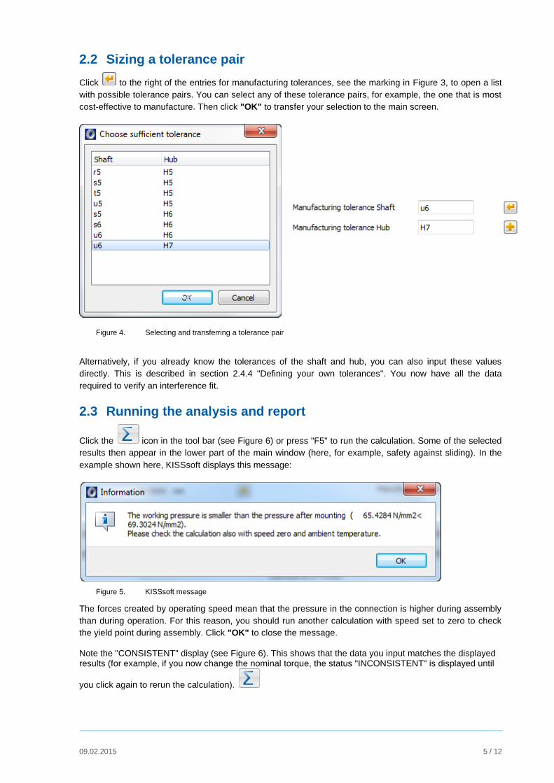
Click to the right of the entries for manufacturing tolerances, see the marking in Figure 3, to open a list
with possible tolerance pairs. You can select any of these tolerance pairs, for example, the one that is most
cost-effective to manufacture. Then click "OK" to transfer your selection to the main screen.
Figure 4. Selecting and transferring a tolerance pair
Alternatively, if you already know the tolerances of the shaft and hub, you can also input these values
directly. This is described in section 2.4.4 "Defining your own tolerances". You now have all the data
required to verify an interference fit.
2.3 Running the analysis and report
Click the icon in the tool bar (see Figure 6) or press "F5" to run the calculation. Some of the selected
results then appear in the lower part of the main window (here, for example, safety against sliding). In the
example shown here, KISSsoft displays this message:
Figure 5. KISSsoft message
The forces created by operating speed mean that the pressure in the connection is higher during assembly
than during operation. For this reason, you should run another calculation with speed set to zero to check
the yield point during assembly. Click "OK" to close the message.
Note the "CONSISTENT" display (see Figure 6). This shows that the data you input matches the displayed results (for example, if you now change the nominal torque, the status "INCONSISTENT" is displayed until
you click again to rerun the calculation).

09.02.2015 6 / 12
The method used to calculate a cylindrical interference fit is applied as specified by DIN 7190, valid for the
elastic range.
Figure 6. Performing the analysis - calling the report
Click the icon in the tool bar (see Figure 6) or press "F6" to write the calculation report that lists all
calculation parameters. You can now, for example, include this report in a proof report.
09.02.2015 7 / 12
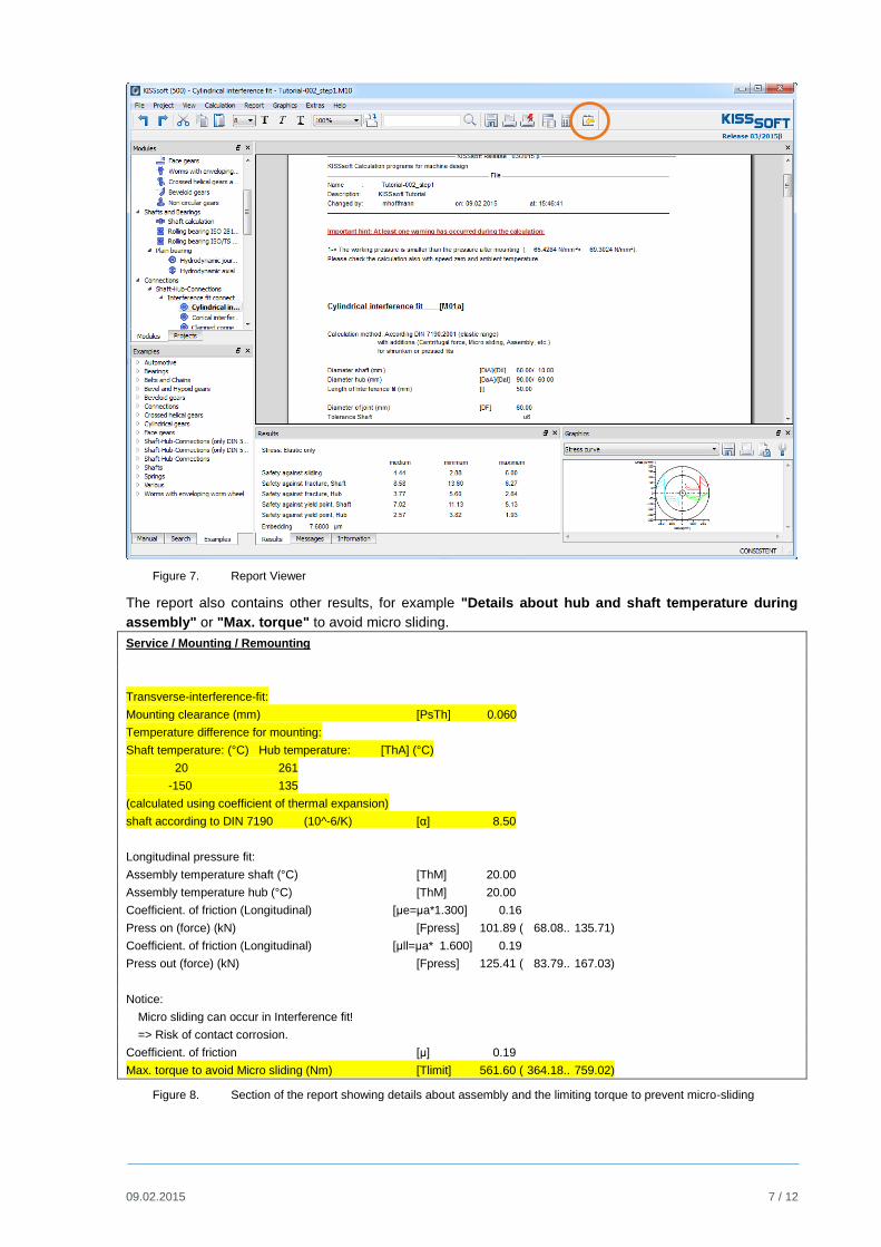
Figure 7. Report Viewer
The report also contains other results, for example "Details about hub and shaft temperature during
assembly" or "Max. torque" to avoid micro sliding.
Service / Mounting / Remounting
Transverse-interference-fit:
Mounting clearance (mm) [PsTh] 0.060
Temperature difference for mounting:
Shaft temperature: (°C) Hub temperature: [ThA] (°C)
20 261
-150 135
(calculated using coefficient of thermal expansion)
shaft according to DIN 7190 (10^-6/K) [α] 8.50
Longitudinal pressure fit:
Assembly temperature shaft (°C) [ThM] 20.00
Assembly temperature hub (°C) [ThM] 20.00
Coefficient. of friction (Longitudinal) [μe=μa*1.300] 0.16
Press on (force) (kN) [Fpress] 101.89 ( 68.08.. 135.71)
Coefficient. of friction (Longitudinal) [μll=μa* 1.600] 0.19
Press out (force) (kN) [Fpress] 125.41 ( 83.79.. 167.03)
Notice:
Micro sliding can occur in Interference fit!
=> Risk of contact corrosion.
Coefficient. of friction [μ] 0.19
Max. torque to avoid Micro sliding (Nm) [Tlimit] 561.60 ( 364.18.. 759.02)
Figure 8. Section of the report showing details about assembly and the limiting torque to prevent micro-sliding
09.02.2015 8 / 12
Click the icon, ringed in orange in Figure 7, to return to the input window.
2.4 Further analysis options and settings
2.4.1 Settings
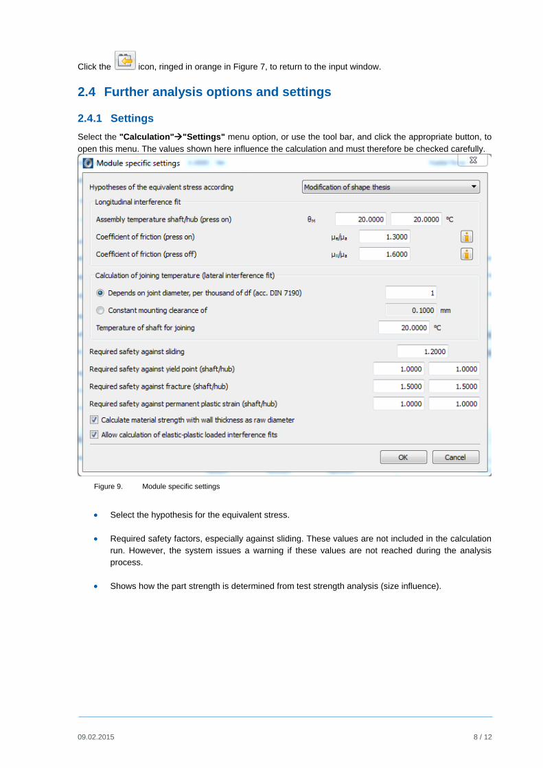
Select the "Calculation""Settings" menu option, or use the tool bar, and click the appropriate button, to
open this menu. The values shown here influence the calculation and must therefore be checked carefully.
Figure 9. Module specific settings
Select the hypothesis for the equivalent stress.
Required safety factors, especially against sliding. These values are not included in the calculation
run. However, the system issues a warning if these values are not reached during the analysis
process.
Shows how the part strength is determined from test strength analysis (size influence).

09.02.2015 9 / 12
2.4.2 Calculate the maximum permissible nominal torque
Now calculate the maximum permissible torque such that the minimum safety against sliding is 1.20. All
other parameters remain as defined above.
To do this, click the "Sizing" button to the right of the input field for nominal torque (see ringed icon 1 in
Figure 10). The software then determines the maximum nominal torque, which in this case is 959.68 Nm. If
you then recalculate the shaft hub connection with this load ( or press F5), the minimum safety
against sliding will be equal to the required minimum safety of 1.2 (see ringed value 3 below in Figure 10):
Figure 10. Sizing to maximum nominal torque

09.02.2015 10 / 12
2.4.3 Hub with varying outer diameters
Click the "Plus" button to the right of the input for the hub outside diameter to allow extended input for
hub geometry. Click this "Plus" button to define a hub with a variable outer diameter. This hub in this
example has 90 mm outer diameter for 25 mm length and 100 mm outer diameter for 25 mm length:
Figure 11. Defining a hub with variable outer diameter
However, you can only input this data if the shaft does not have a bore. Otherwise the following error
message appears.
Figure 12. Error message

09.02.2015 11 / 12
2.4.4 Defining your own tolerances
Click the "Plus" button to the right of the input field for tolerances to input your own tolerance values. To
do this, set the flag in the checkbox for "Own tolerances" and input the value you require:
Figure 13. Defining your own tolerances
2.4.5 Influence of temperature
The reference temperature is 20°C.
Note: the maximum operating temperature is 700°C.
However, if you input a different operating temperature in the main screen, the interference pressure
changes as a function of the difference in the coefficient of thermal expansion of the shaft/hub material.
You can modify this by setting the material to "Own Input" in the material properties screen.
Figure 14. Inputting your own material (in particular coefficient of thermal expansion) and operating temperature
Click (upper right-hand marking in Figure 14) to the right of the material selection list to modify the
material properties:

09.02.2015 12 / 12
Figure 15. Defining a specific material
The data you input for this new material only applies to this calculation. After you save this file, this data is
no longer available to any other calculation. However, if you want other calculations to be able to use the
data for this new material, you must store this information in the material database.
2.4.6 Additional loads
In the "Radial force" and "Bending moment" input fields you can also input additional radial forces and
bending moments (for example, those that result from the tooth forces in a gear). The software then also
calculates additional stress. To ensure no gaps occur between the hub and the shaft, the additional
pressure must be less than the minimum interference pressure. If not, an error message appears and the
calculation is not performed.


![USTA TrafficAnalysisBriefing V7 0 20150530 FINAL[1] · PDF file1."Executive"Summary" ... In2014thethreemajorGulfcarriers" –"Emirates,"Qatar"Airways"and"Etihad" Airways"–"carried"some"4.3"million"passengers"intoandout"of"the](https://static.fdocuments.in/doc/165x107/5aa125967f8b9a46238b5bf2/usta-trafficanalysisbriefing-v7-0-20150530-final1-in2014thethreemajorgulfcarriers.jpg)