Kirchoffs Law With Cramers Rule
14
Kirchoff’s Laws Direct: KCL, KVL, Ohm’s Law ⇒ V IR VG I = ⇒ = G R = −1 Ohm’s Law: V I I 1 1 2 3 6 = ⋅ = ⋅ V I 2 3 12 = ⋅ (always get 1 equation/Resistor) KCL: A: - + B: 5 0 5 0 1 2 3 1 2 3 I I I I I I + − = − − + = eq. are dependent (in general, get n-1 indep. for nodes) KVL: − + − = V V 1 2 24 0 write 1 loop equation for each loop with a voltage not in the current set of equations. ⇒ Eliminate either V 1 or I using Ohm’s Law eq: A: − + + − = 5 3 6 12 0 1 1 2 V V V ⇒ − − = + − 1 3 1 6 1 12 1 2 1 1 5 24 V V KVL: − + − = V V 1 2 24 0 Cramer’s Rule: A X B [ ] ⋅ = v v X Det A BA Det A i i i N = [ ] [ ] − + 0 1 1 .. .. 5 24V + - 6Ω 3Ω V 1 V 2 + I 1 I 2 - + 12Ω I 3 A B
-
Upload
roy-bernard-d-basa -
Category
Documents
-
view
68 -
download
4
Transcript of Kirchoffs Law With Cramers Rule

Kirchoff’s Laws Direct:
KCL, KVL, Ohm’s Law ⇒ V IR VG I= ⇒ =G R= −1
Ohm’s Law: V I I1 1 23 6= ⋅ = ⋅V I2 312= ⋅
(always get 1 equation/Resistor)
KCL:A: - +
B:
5 0
5 01 2 3
1 2 3
I I I
I I I
+ − =− − + =
eq. are dependent
(in general, get n-1 indep. for nodes)
KVL: − + − =V V1 224 0 write 1 loop equation for each loop with a voltagenot in the current set of equations.
⇒ Eliminate either V1 or I using Ohm’s Law
eq: A: − + + − =53 6 12
01 1 2V V V
⇒− −
=
+
−1
3
1
6
1
12 1
21 1
5
24
V
V
KVL: − + − =V V1 224 0
Cramer’s Rule: A X B[ ] ⋅ =v v
XDet A B A
Det Ai
i i N
= [ ][ ]
− +0 1 1.. ..
524V
+
-6Ω3ΩV1
V2+I1 I2
- +
12Ω I3A
B

We can always write in terms of only V, or I variables using ohm’s law:
KCL: A: − + + =I I I1 2 3 0
KVL: M1: − + + =12 2 4 01 2I I
M2 : − + − =4 6 8 02 3 1I I I
−
− −
=
1 1 1
2 4 0
8 4 6
0
12
0
1
2
3
I
I
I
Note:
if V IR=R G= −1
⇔V I G
R
+
B
2Ω 6Ω
4Ω
12V
V1 V3
8 1I
A
M1 M2
V2
+ +
+-
-
+
I3
I2
I1
CurrentDependentVoltage Source:
+
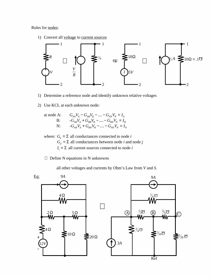
Rules for nodes:
1) Convert all voltage to current sources
1) Determine a reference node and identify unknown relative voltages
2) Use KCL at each unknown node:
at node A: G V G V G V IAA A AB B AN N A− − − =....B: -G V G V G V IAB A BB B BN N B+ − − =....N: -G V G V G V IAN A BN B NN N N+ − − =....
where: Gii = Σ all conductances connected to node iGji = Σ all conductances between node i and node j
Ii = Σ all current sources connected to node i
⇒ Define N equations in N unknowns
all other voltages and currents by Ohm’s Law from V and S.
2 2 22
1 1 1
R
V
10Ω
5V
1
1R
V
R+-
⇔ ⇔I
12 A 10 1Ω = .eg:
⇒4 Ω
2 Ω 5 Ω
4 Ω10 Ω
20 Ω+
-
9A
12V
Eq:
3A
14
Ref
110 1
20
14
12
15
9A
A B C
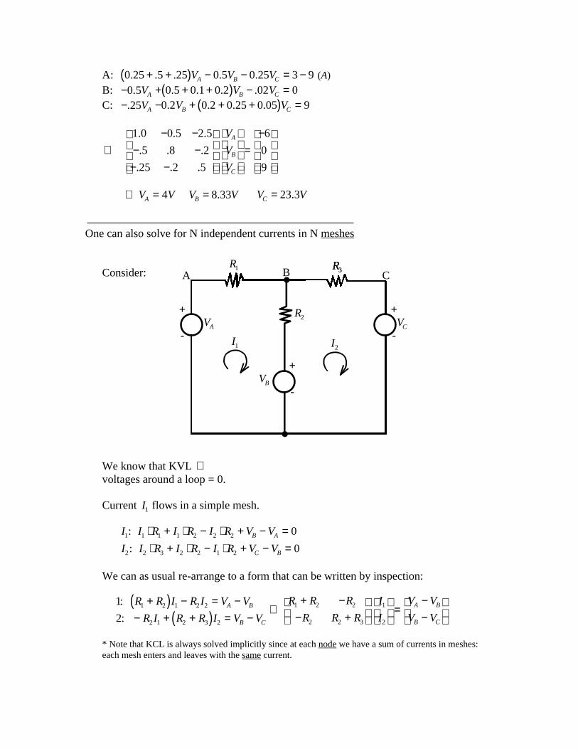
A: 0 25 5 25 0 5 0 25 3 9. . . . .+ +( ) − − = −V V VA B C (A)
B: −0 5. VA + + +( ) − =0 5 0 1 0 2 02 0. . . .V VB C
C: −.25VA − + + +( ) =0 2 0 2 0 25 0 05 9. . . .V VB C
⇒1 0 0 5 2 5
5 8 2
25 2 5
6
0
9
. . .
. . .
. . .
− −− −− −
=−
V
V
V
A
B
C
⇒ =V VA 4 V VB = 8 33. V VC = 23 3.
One can also solve for N independent currents in N meshes
Consider:
We know that KVL ⇒voltages around a loop = 0.
Current I1 flows in a simple mesh.
I I R I R I R V V
I I R I R I R V VB A
C B
1 1 1 1 2 2 2
2 2 3 2 2 1 2
0
0
:
:
⋅ + ⋅ − ⋅ + − =⋅ + ⋅ − ⋅ + − =
We can as usual re-arrange to a form that can be written by inspection:
1
21 2 1 2 2
2 1 2 3 2
1 2 2
2 2 3
1
2
:
:
R R I R I V V
R I R R I V V
R R R
R R R
I
I
V V
V VA B
B C
A B
B C
+( ) − = −− + +( ) = −
⇒+ −
− +
=−−
* Note that KCL is always solved implicitly since at each node we have a sum of currents in meshes:each mesh enters and leaves with the same current.
R1 R3R3A B C
VA VC
VB
R2
I2I1
+
-
+
-
+
-

In general:
1) Connect each current source with parallel res. to voltage source with series R.
2) Select a current variable and mesh for each simple loop (usually we traverseeach loop in same direction, ie, clockwise.
3) Use KVL for each loop in terms of the mesh current variable.
iff no dependent sources:
1: R I R I R I VN N11 1 12 2 1 1− − − =...2: − − − − =R I R I R I VN N12 1 22 2 2 2...N: − − − − =R I R I R I VN N NN N N1 1 2 2 ...
Rii = sum of all resistance in mesh IRij = sum of all common resistance to meshes I,JVI = sum of voltage rises in mesh I, in direction of current I1
Eq: A Wheatstone Bridge
⇒ 12 8 20 8 20 241 2 3+ +( ) − − =I I I− + + +( ) − =8 8 4 6 6 01 2 3I I I− − + + +( ) =20 6 20 6 10 01 2 3I I I
40 8 20
8 18 6
20 6 36
24
0
0
1
2
3
− −− + −− − +
⋅
=
I
I
I
I1
I2
I3
12 Ω
4 Ω
10 Ω20 Ω
8 Ω
24V
+
-

How to solve this system?⇒ Gaussian Elimination to Triangular form:
1
2
3
20 4 10
4 9 3
10 3 18
12
0
0
:
:
:
− −− −− −
=
(divide both sides by 2)
3 10 059
809
53⋅ = +[ ] [ ]− −
1
2
3
0
4 9 3
10 3 18
12
0
0
1309
173'
−
− −− −
=
3 3 016
106⋅ = [ ] [ ]− =-1
2
1
2
3
0
0
10 3 18
12
0
0
1309
173
175
172
'
'
−
−
− −
=
2 2217
173
23
349' '⋅ ⋅ = ⋅ = [ ]− 017
3
1
2
3
0 0
0
10 3 18
12
0
0
969
173
172
'
" −
− −
=
⇒ 969 1 1
5412⋅ = =I V I A
Then 2 173
54
172 2 2
34' = ⋅ = ⋅ ⇒ =+ I I A
3' ⇒ + ⋅ + ⋅ = ⋅ ⇒ =10 3 1854
34 3
34I A I3

Dependent Voltage & Current Sources:
We model the activity of many active components by use of a “programmable”voltage or current source whose strength is a function of the voltage or currentselsewhere in the circuit:
Eq:
if we choose B as the reference node ⇒
A: . . .8 2 2 5+( ) − =V VA C
C: −( ) + +( ) = − +. . .2 2 3 5 4 1V V IA C
now I V VA C= ⋅ −( )0 2.
⇒1 2
1 1 3
−−
=−
.
.
V
V
s
sA
C
I14 1I
.8v
.2v .3v
A B
C
5A

Superposition for Circuits
Consider:
We could solve this by either node or mesh analysis, but there may be a simplerapproach:
If we suppress source #1 (i.e. make a short circuit) we can find I I1 2' ', .
Similarly, I I1 2, could be written without source #2.
Total currents and voltages superpose ⇒ suppress one at a time and thensuperpose the results:
Suppress 1:
⇒ 24 12 6 3 5V I= + +( )( ) ⋅ '
So I A VA' '= ⋅ = ⇒ = +7108
24149
563
24 volt
I1
12818
' = −I2
12818
' =
6Ω 3Ω
12Ω5Ω
12Ω
A B
24
I1
A B
2:
I2I1
+
-+
-
C
1: 30
24
6Ω 3Ω
5Ω
12Ω

Now: Suppress I2 , run I1
30 6 12 8 1V I= + ( )( ) ⋅ ' '
6Ω
12Ω
3Ω
5Ω12Ω
I1' ' I2
' '
+
-30

Exponential Excitation of circuits: Admittance & Impedance
Idea: Exponential function is easy to analyze ⇒simple to add/multiply/integrates, etc.Also is a common case for circuit excitation
Consider:
where V Aest= for complex s, A, real t.
We know all currents are same in circuit, V V V VR C L+ + = KVL
V i t RR = ( ) ⋅ VC
i t dtC = ⋅ ( )∫1V L
di t
dtL = ( )
or i tV t
RRR( ) = ( )
i t CdV t
dtLC( ) = ( )
i tL
V t dtL C( ) = ( )∫1
for our circuit V t Aest( ) = ⇒ V t A eRst( ) = ' , V t A eC
st( ) = ' ' …
where: Ae A A A est st= + +( )' ' ' ' ' ' KVL
we have i tA
ReR
st( ) = 'i t C A s eC
st( ) = ⋅ ⋅' ' iA e
sLL
st
= ' ' '
+
-
R C
V VL
i
L
VRVC

Note: for this kind of excitation, i t C A s eLst( ) = ⋅ ⋅' '
= ⋅ ( )sC V tC
i ts
V t
i tR
V t
L L L
R R
( ) = ( )
( ) = ( )
1
1
So: sC has same units/behavior as 1R
: conductance.
Eg. 2:
Parallel ⇒ admittances ⇒
11
= +Vsv
⇒ =+
VI
s1
for i t e t( ) = −10 2 s A= − =2 10,
V e est t=−
= − = − −101 2
10 10 2 volts
i 1Ω
iR iC
1F
i
V
ref
1s11

Sinewave (Sinusodial) excitation:
We know: e o i oio = +cos sin
⇒ cosoe eio io
= + −
2sin o
e e
i
io io
= − −
2
We wish to study circuits with excitation: v t V wt( ) = +( )cos φ
= +( ) = ++ − − −Ve e v e v eiwt i iwt i
iiwt iwt
2 2ϕ ϕ
vV
ei1 2
= ϕ vV
e i2 2
= − ϕ
note V is complex.
We define:
for s iw=
R C L
sC
R sL
iwC
R iwL
sL
sC
R iwL
iwC
Admittance
Impedance
sinusoid case
1R
1
1
1 1
1
( )

Admittances compose like conductances, Impedances compose like resistances.
So for our circuit: v t R i t L i t dtdi tdt C( ) = ⋅ ( ) + ⋅ + ( )( ) ∫1
for i t Iest( ) =
⇒ ( ) = ⋅ + ⋅ ⋅ +( )v t R I L I s eIsC
st
or IV
R Ls
V
z ssC
=+ +
=1 ( )
we write impedances as Z s( ) , admittance as Y(s)
so i t IeV
R Lsest
sC
st( ) = =+ +
⋅1
eq: if V e t= ⋅ −10 2 (10 0V t@ = → decreasing)
R = 1Ω L H= 12 C F= 1
2
i t e es
s
st t( ) =+ +
= − −101
102
2
2 (Amps)
Basic Trick: Extend the circuit techniques for node and mesh analysis to alsohandle Impedence and Admittances
⇒ generalize circuits which can be analyzed.
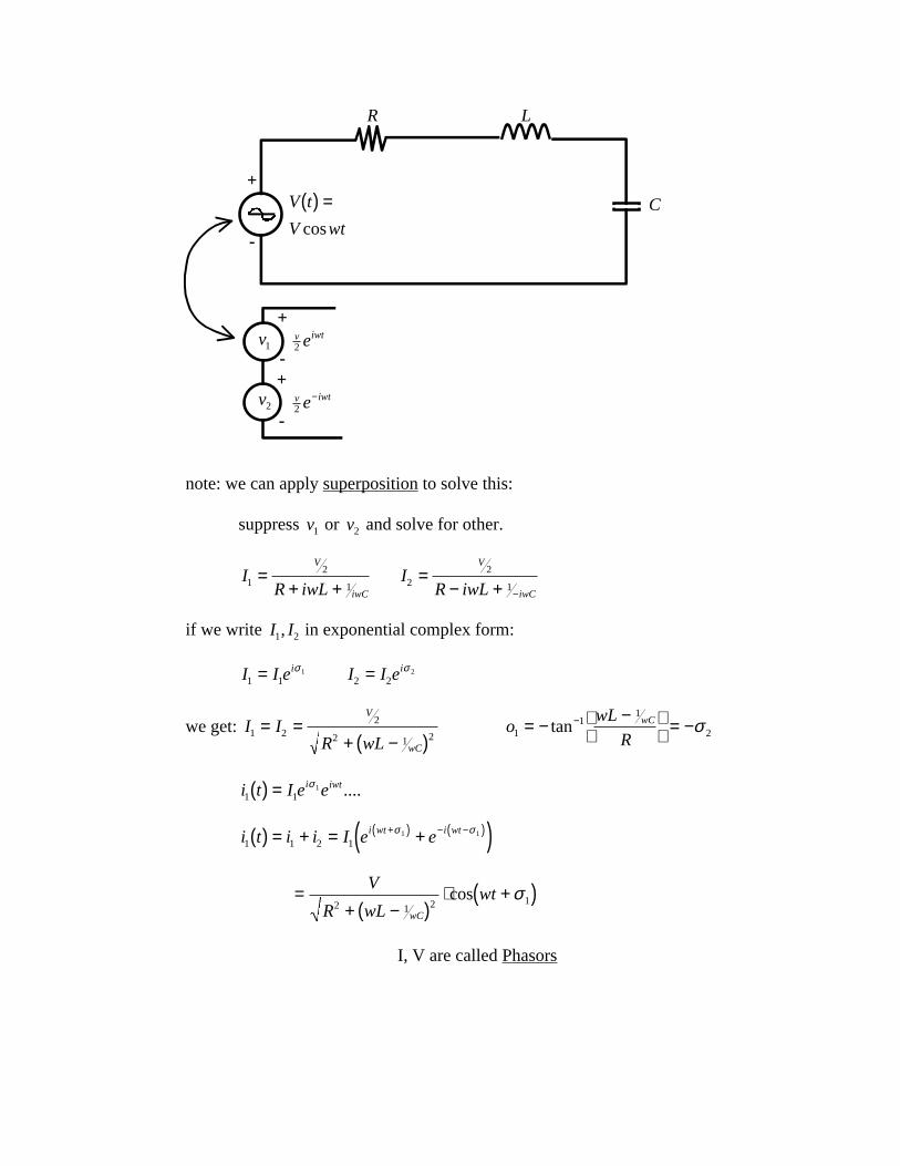
note: we can apply superposition to solve this:
suppress v1 or v2 and solve for other.
IR iwL
V
iwC1
2
1=
+ +I
R iwL
V
iwC2
2
1=
− + −
if we write I I1 2, in exponential complex form:
I I ei1 1
1= σ I I ei2 2
2= σ
we get: I IR wL
V
wC
1 22
2 1 2= =
+ −( )o
wL
RwC
11
1
2= − −
= −−tan σ
i t I e ei iwt1 1
1( ) = σ ....
i t i i I e ei wt i wt1 1 2 1
1 1( ) = + = +( )+( ) − −( )σ σ
=+ −( )
⋅ +( )V
R wLwt
wC2 1 2 1cos σ
I, V are called Phasors
R L
CV t
V wt
( ) =cos
+
-
+
-+
-
v iwte2
v iwte2−
v1
v2