
Kinematics of Machines (NME-502) -...
73
Kinematics of Machines (NME-502)
Transcript of Kinematics of Machines (NME-502) -...
Kinematics of Machines
(NME-502)
Unit – IV
Gears and Gear Train
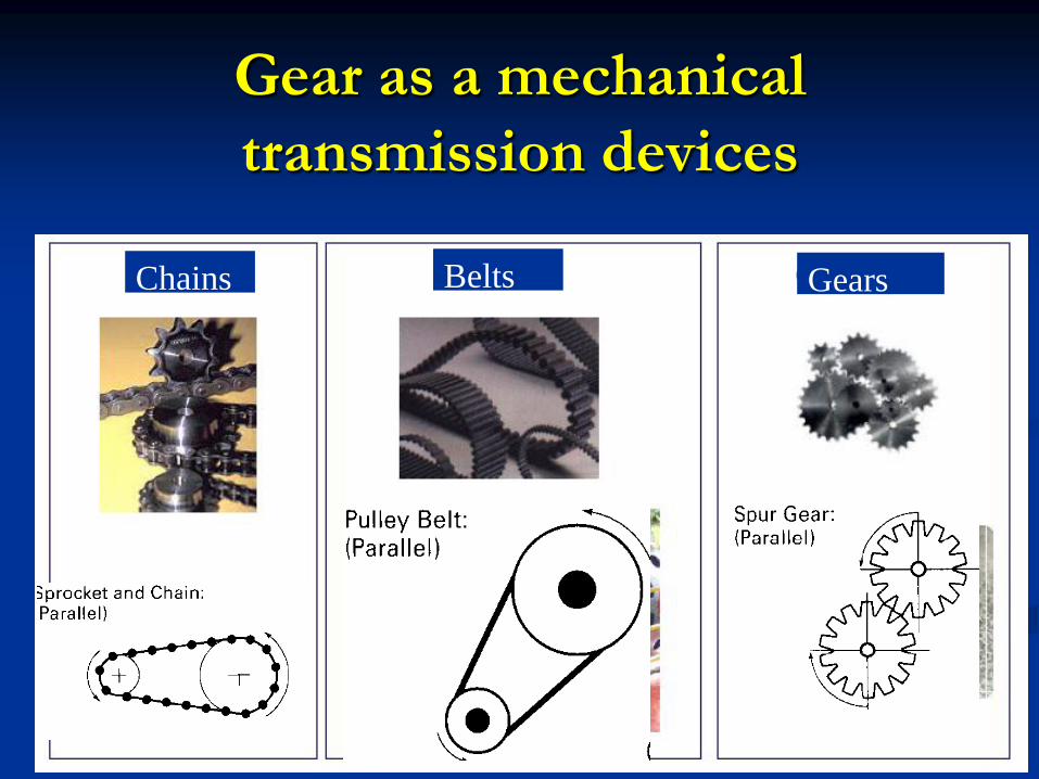
Gear as a mechanical
transmission devices
Chains Belts Gears
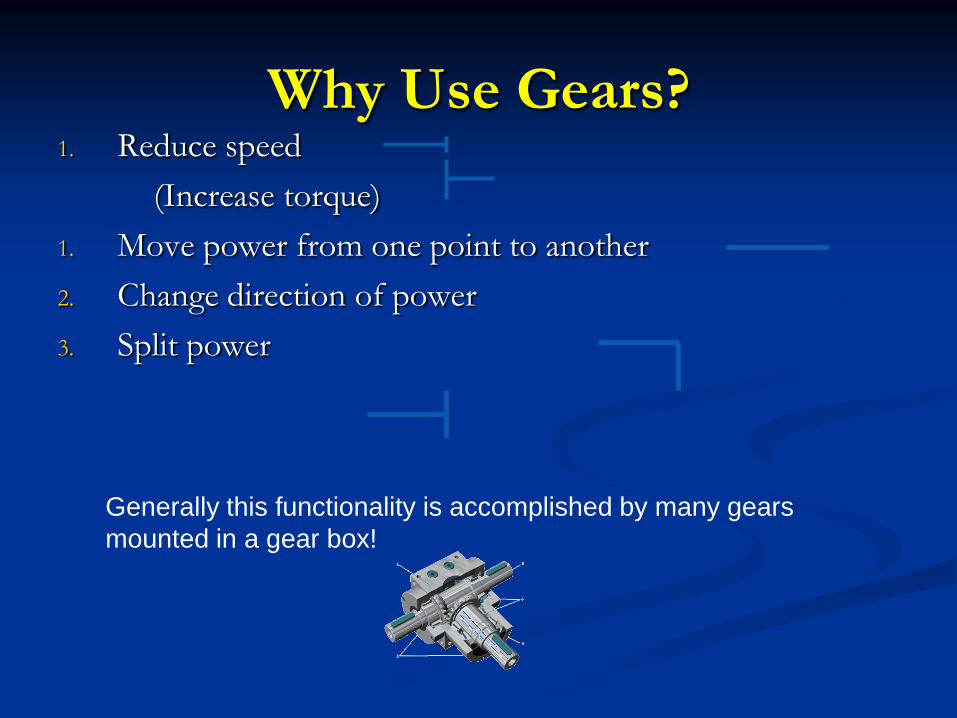
Why Use Gears? 1. Reduce speed
(Increase torque)
1. Move power from one point to another
2. Change direction of power
3. Split power
Generally this functionality is accomplished by many gears
mounted in a gear box!
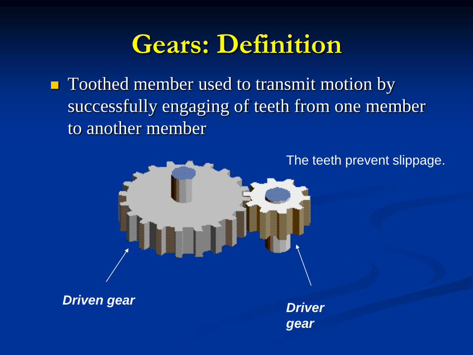
Gears: Definition
Toothed member used to transmit motion by
successfully engaging of teeth from one member
to another member
Driver
gear
Driven gear
The teeth prevent slippage.
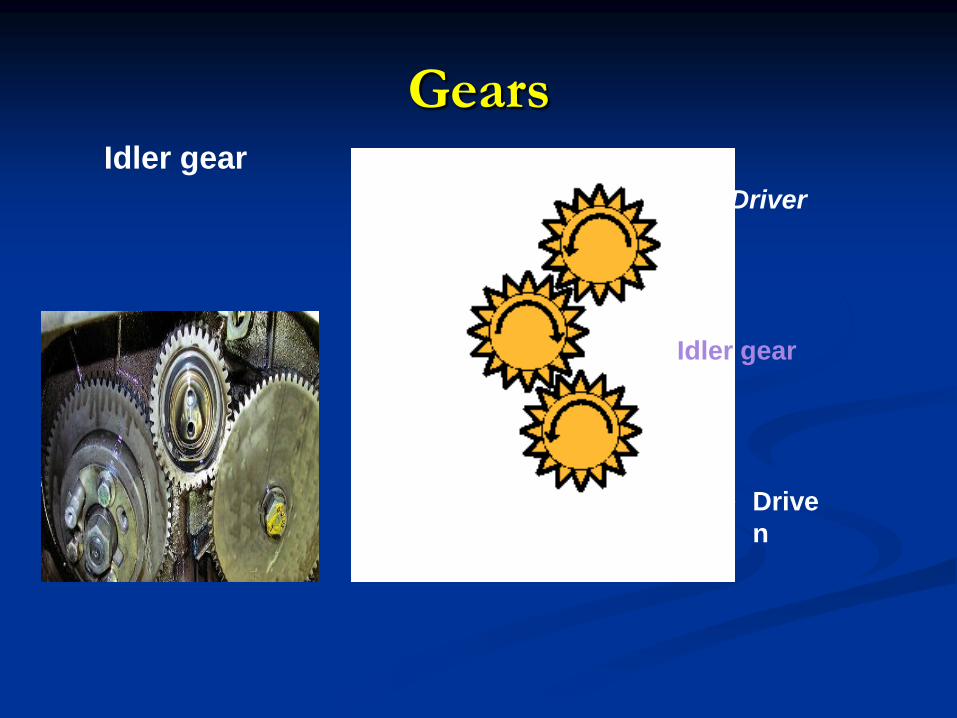
Gears
Idler gear
Driver
Drive
n
Idler gear
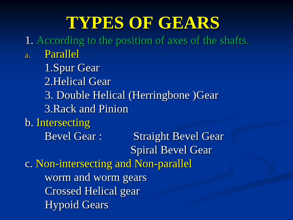
TYPES OF GEARS 1. According to the position of axes of the shafts.
a. Parallel
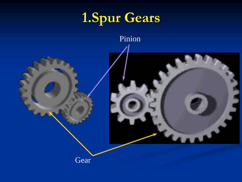
1.Spur Gear
2.Helical Gear
3. Double Helical (Herringbone )Gear
3.Rack and Pinion
b. Intersecting
Bevel Gear : Straight Bevel Gear
Spiral Bevel Gear
c. Non-intersecting and Non-parallel
worm and worm gears
Crossed Helical gear
Hypoid Gears
a) Parallel Shaft
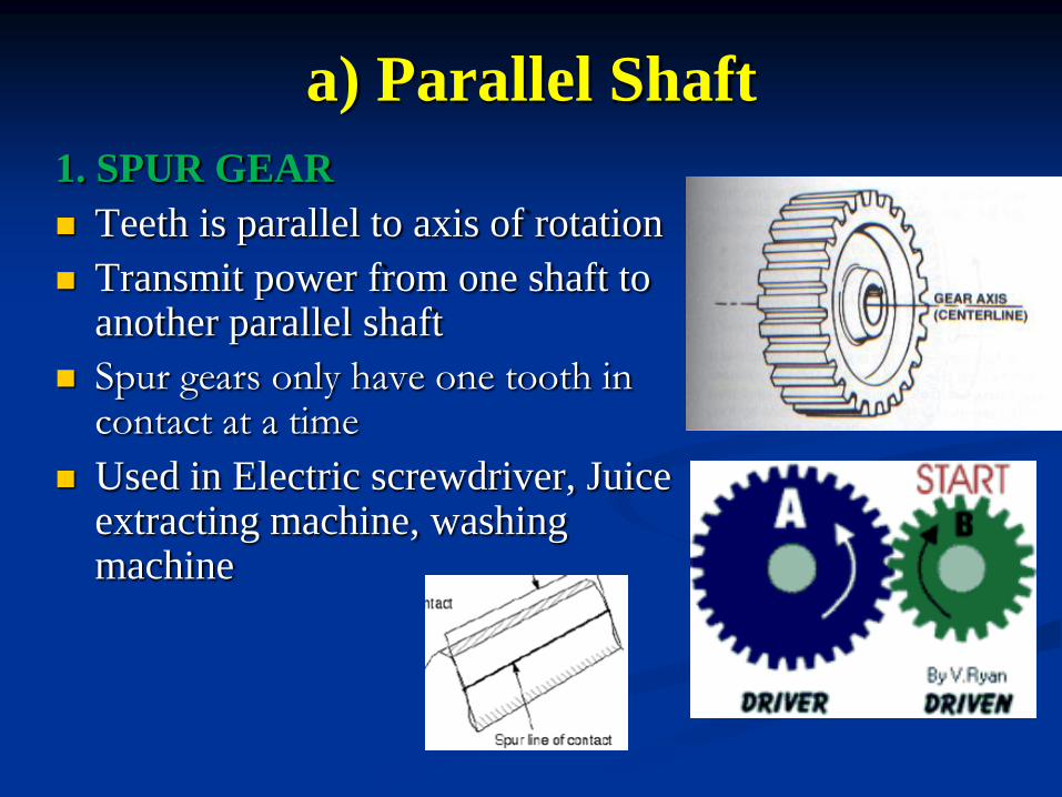
1. SPUR GEAR
Teeth is parallel to axis of rotation
Transmit power from one shaft to another parallel shaft
Spur gears only have one tooth in contact at a time
Used in Electric screwdriver, Juice extracting machine, washing machine

2. Helical Gear
Are quieter than spur gears
Two teeth at a time contact
Has a tendency to move shaft for and aft(Due to axial
Thrust)
Are left and right handed
Opposites on parallel shafts
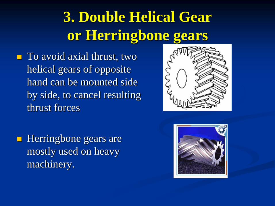
3. Double Helical Gear
or Herringbone gears
To avoid axial thrust, two
helical gears of opposite
hand can be mounted side
by side, to cancel resulting
thrust forces
Herringbone gears are
mostly used on heavy
machinery.
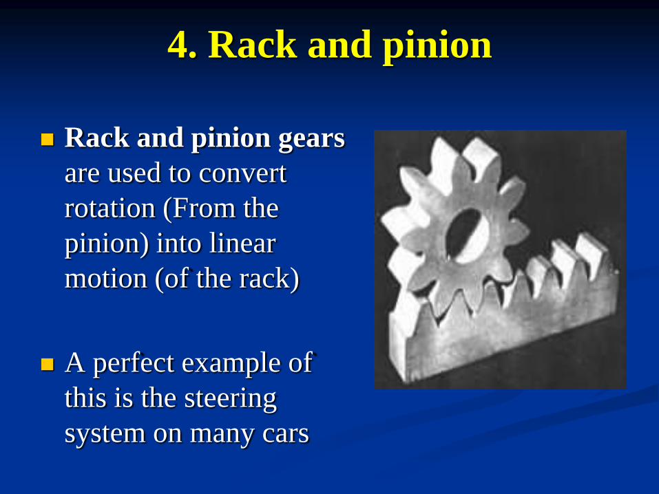
4. Rack and pinion
Rack and pinion gears
are used to convert
rotation (From the
pinion) into linear
motion (of the rack)
A perfect example of
this is the steering
system on many cars
(b)Intersecting Shaft
Bevel Gear
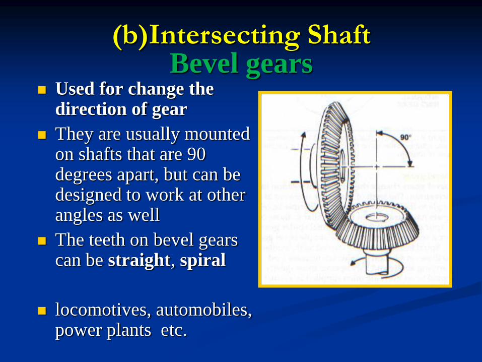
Bevel gears Used for change the
direction of gear
They are usually mounted on shafts that are 90 degrees apart, but can be designed to work at other angles as well
The teeth on bevel gears can be straight, spiral
locomotives, automobiles, power plants etc.
(b)Intersecting Shaft
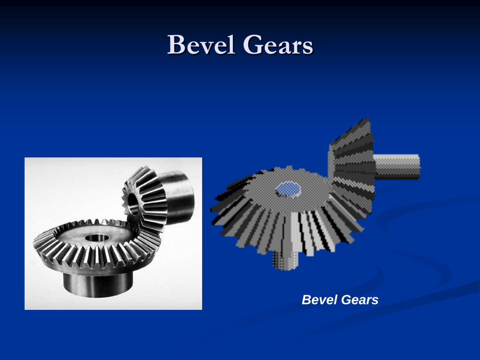
Bevel Gears
Bevel Gears
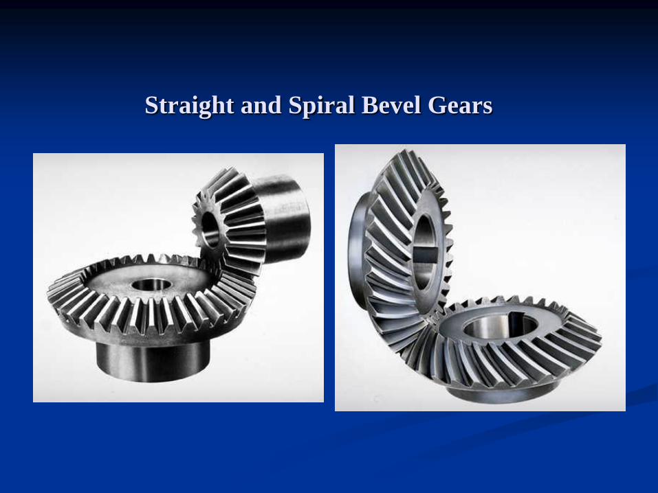
Straight and Spiral Bevel Gears
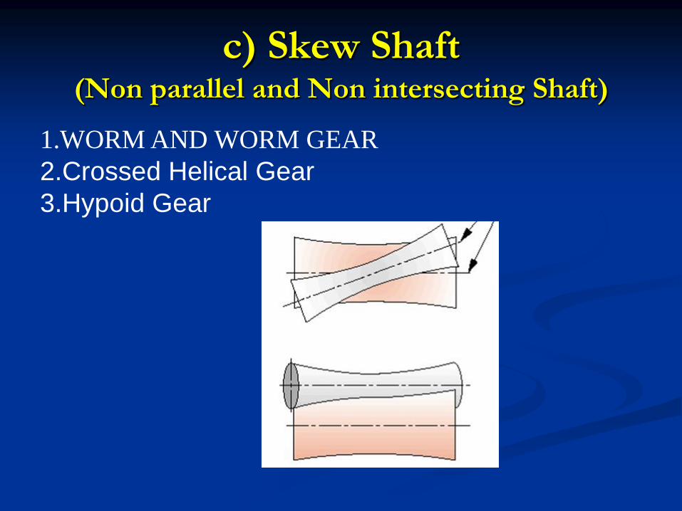
c) Skew Shaft (Non parallel and Non intersecting Shaft)
1.WORM AND WORM GEAR
2.Crossed Helical Gear
3.Hypoid Gear
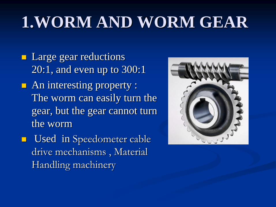
1.WORM AND WORM GEAR
Large gear reductions
20:1, and even up to 300:1
An interesting property :
The worm can easily turn the
gear, but the gear cannot turn
the worm
Used in Speedometer cable
drive mechanisms , Material
Handling machinery
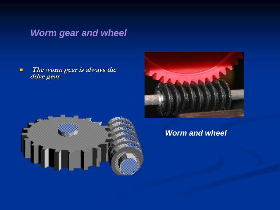
The worm gear is always the drive gear
Worm and wheel
Worm gear and wheel
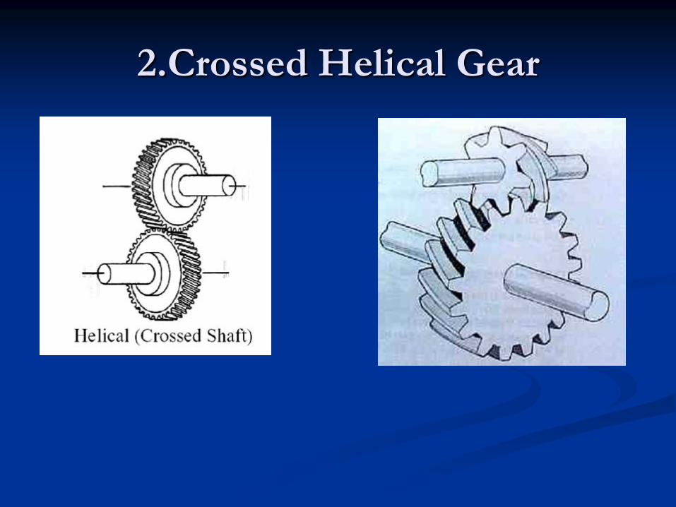
2.Crossed Helical Gear
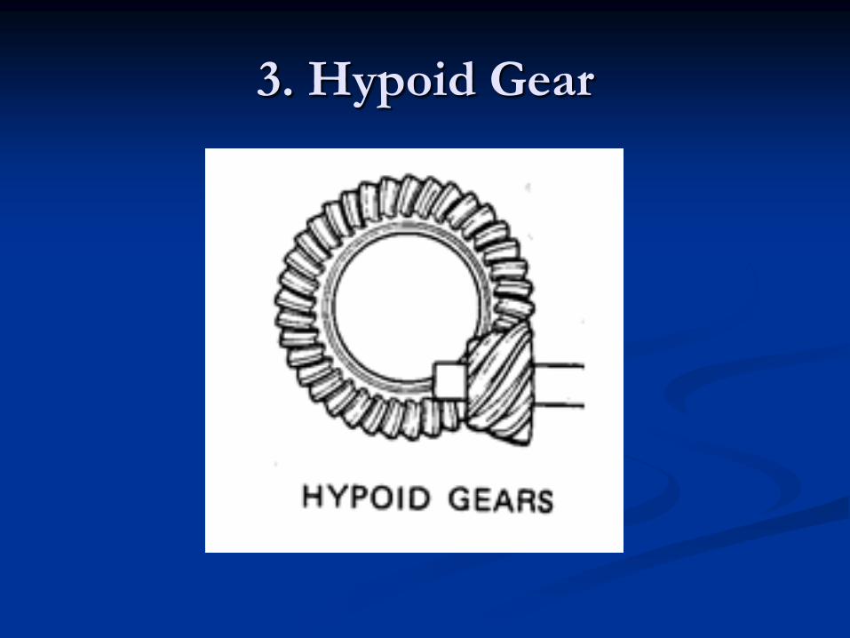
3. Hypoid Gear
Classification bases on Types of
Gears
1. Internal Gear
2. External Gear
3. Rack and Pinion
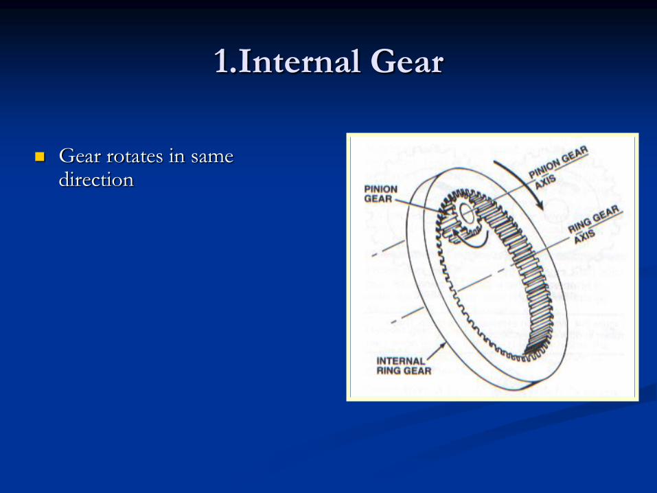
1.Internal Gear
Gear rotates in same direction
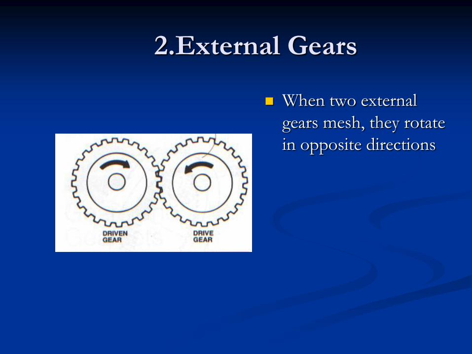
2.External Gears
When two external
gears mesh, they rotate
in opposite directions
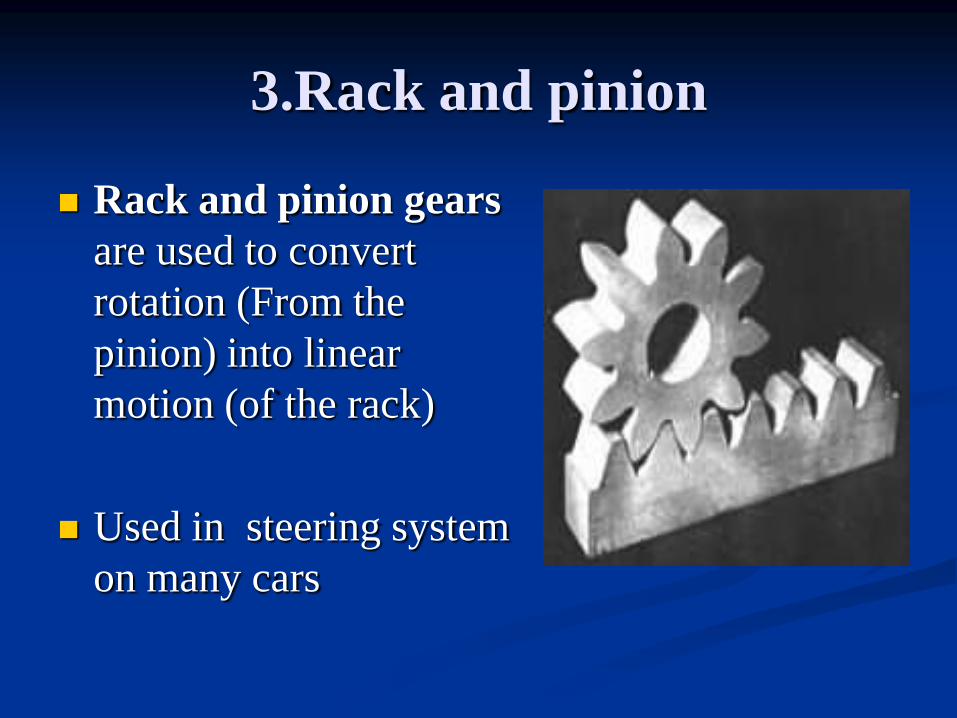
3.Rack and pinion
Rack and pinion gears
are used to convert
rotation (From the
pinion) into linear
motion (of the rack)
Used in steering system
on many cars
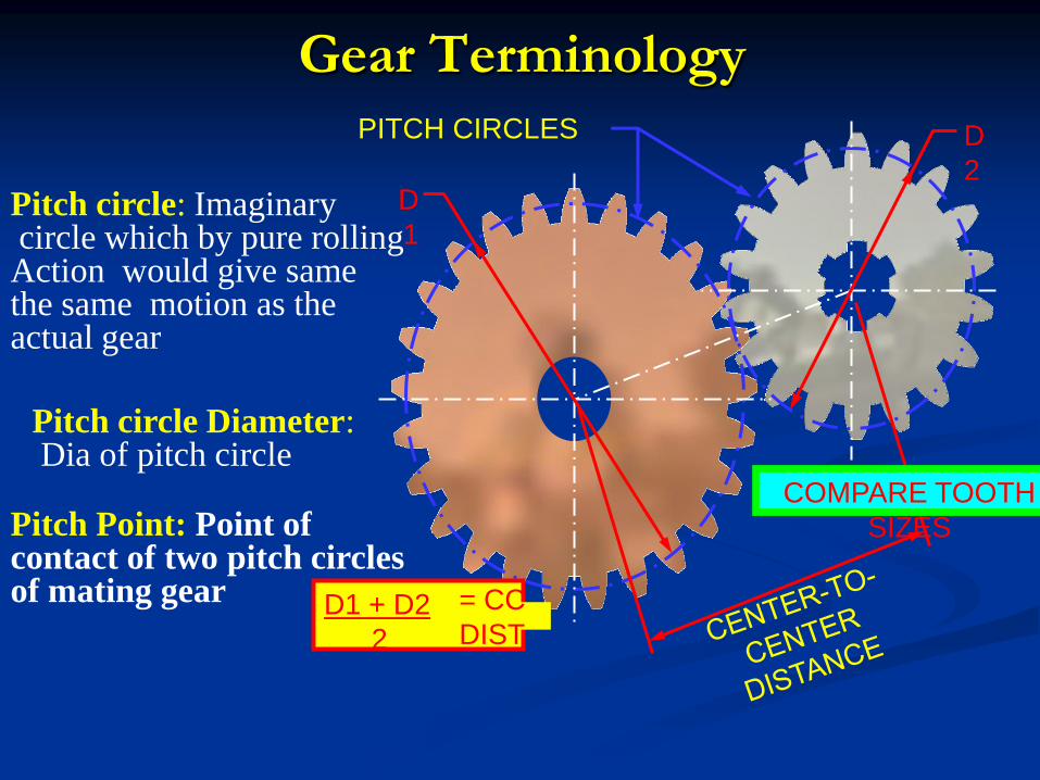
Gear Terminology
PITCH CIRCLES
D1 + D2
2
= CC
DIST
D
1
D
2
COMPARE TOOTH
SIZES
Pitch circle: Imaginary circle which by pure rolling Action would give same the same motion as the actual gear
Pitch Point: Point of contact of two pitch circles of mating gear
Pitch circle Diameter: Dia of pitch circle
Fillet radius Clearanc
e
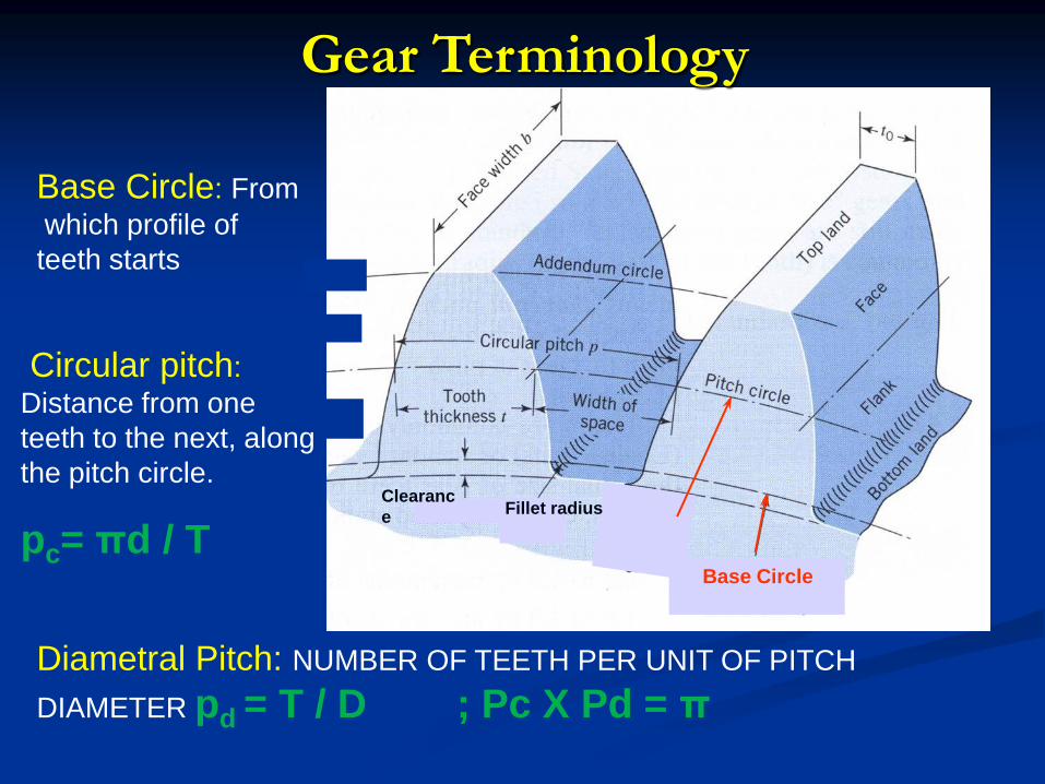
Base Circle
Base Circle: From
which profile of
teeth starts
Circular pitch:
Distance from one
teeth to the next, along
the pitch circle.
pc= πd / T
Gear Terminology
Diametral Pitch: NUMBER OF TEETH PER UNIT OF PITCH
DIAMETER pd = T / D ; Pc X Pd = π
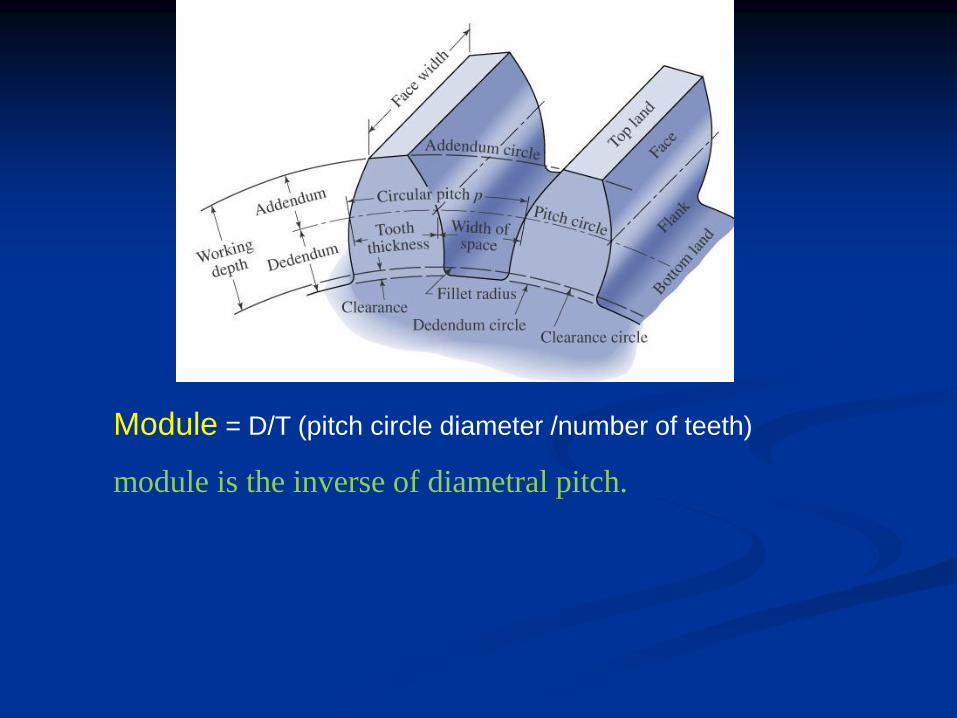
Module = D/T (pitch circle diameter /number of teeth)
module is the inverse of diametral pitch.
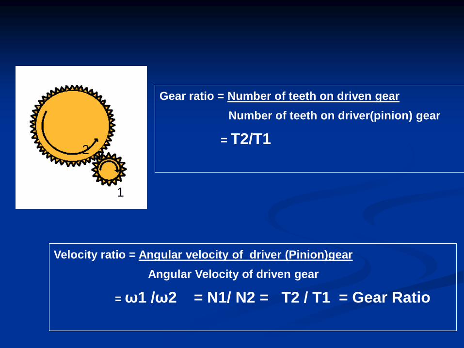
Gear ratio = Number of teeth on driven gear
Number of teeth on driver(pinion) gear
= T2/T1
Velocity ratio = Angular velocity of driver (Pinion)gear
Angular Velocity of driven gear
= ω1 /ω2 = N1/ N2 = T2 / T1 = Gear Ratio
2
1
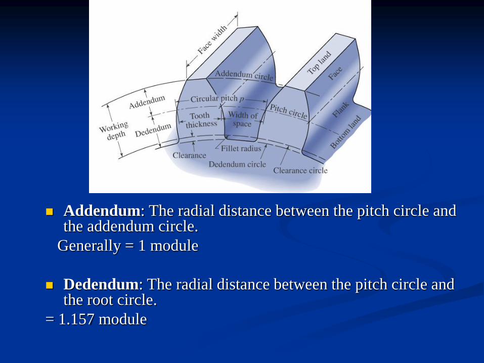
Addendum: The radial distance between the pitch circle and the addendum circle.
Generally = 1 module
Dedendum: The radial distance between the pitch circle and the root circle.
= 1.157 module
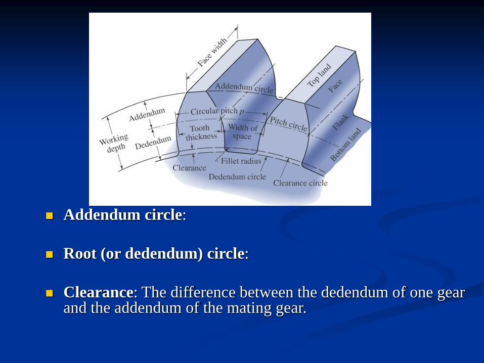
Addendum circle:
Root (or dedendum) circle:
Clearance: The difference between the dedendum of one gear and the addendum of the mating gear.
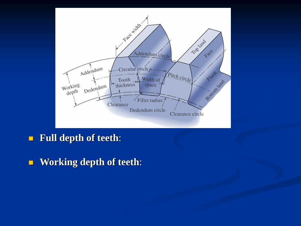
Full depth of teeth:
Working depth of teeth:
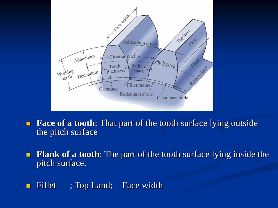
Face of a tooth: That part of the tooth surface lying outside the pitch surface
Flank of a tooth: The part of the tooth surface lying inside the pitch surface.
Fillet ; Top Land; Face width
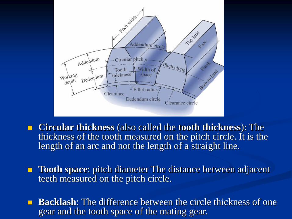
Circular thickness (also called the tooth thickness): The thickness of the tooth measured on the pitch circle. It is the length of an arc and not the length of a straight line.
Tooth space: pitch diameter The distance between adjacent teeth measured on the pitch circle.
Backlash: The difference between the circle thickness of one gear and the tooth space of the mating gear.
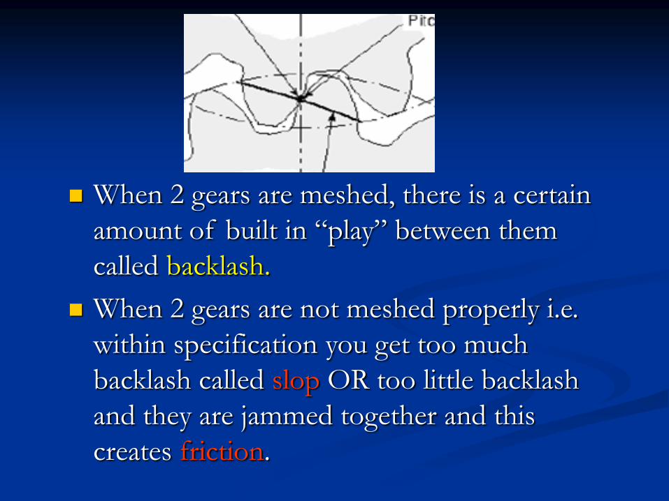
When 2 gears are meshed, there is a certain
amount of built in “play” between them
called backlash.
When 2 gears are not meshed properly i.e.
within specification you get too much
backlash called slop OR too little backlash
and they are jammed together and this
creates friction.
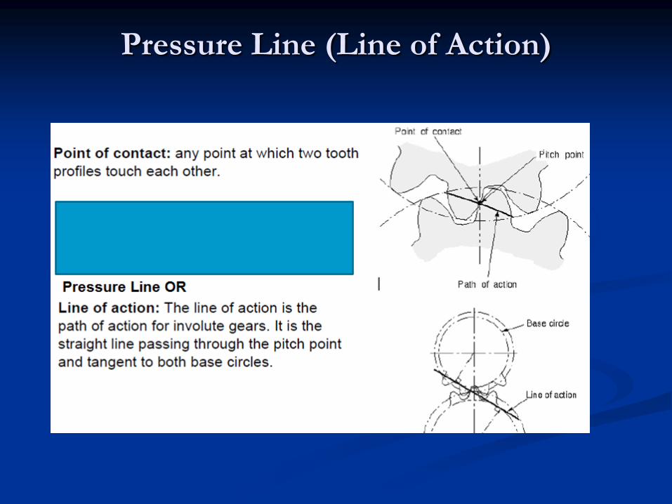
Pressure Line (Line of Action)
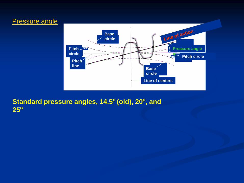
Pressure angle
Pitch
line
Line of centers
Base
circle
Base
circle
Pitch
circle Pitch circle
Pressure angle
φ
Standard pressure angles, 14.5o (old), 20o, and
25o
Types of Profile of Gear Teeth
Conjugate Teeth:
Any arbirary profile of teeth ; Profile of another teeth
is obtained by law of gearing
1 Cycloidal Profile Teeth
2 Involute Profile Teeth
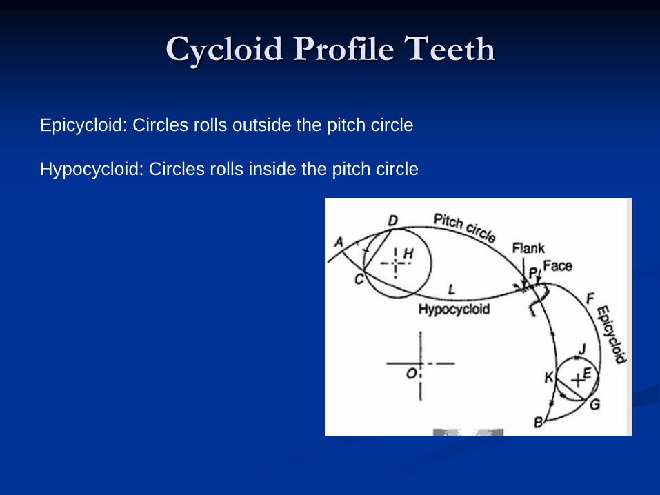
Cycloid Profile Teeth
Epicycloid: Circles rolls outside the pitch circle
Hypocycloid: Circles rolls inside the pitch circle
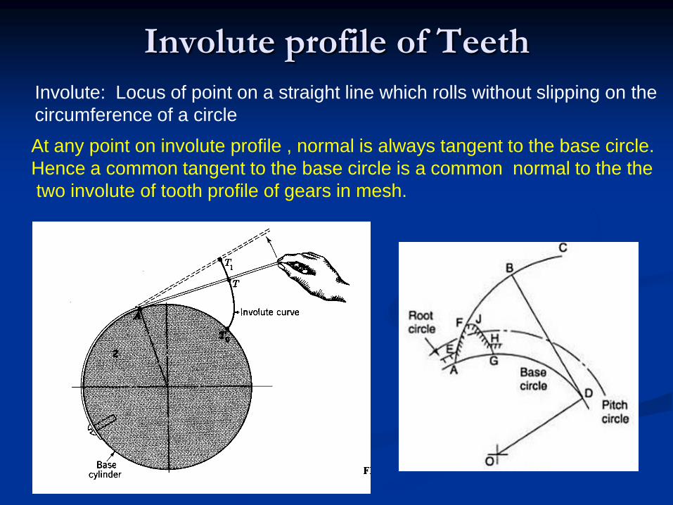
Involute profile of Teeth
Involute: Locus of point on a straight line which rolls without slipping on the
circumference of a circle
At any point on involute profile , normal is always tangent to the base circle.
Hence a common tangent to the base circle is a common normal to the the
two involute of tooth profile of gears in mesh.
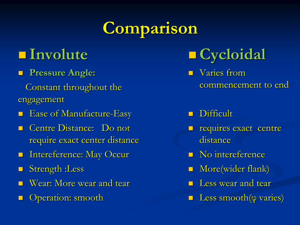
Comparison
Involute Pressure Angle:
Constant throughout the
engagement
Ease of Manufacture-Easy
Centre Distance: Do not
require exact center distance
Intereference: May Occur
Strength :Less
Wear: More wear and tear
Operation: smooth
Cycloidal Varies from
commencement to end
Difficult
requires exact centre
distance
No intereference
More(wider flank)
Less wear and tear
Less smooth(φ varies)
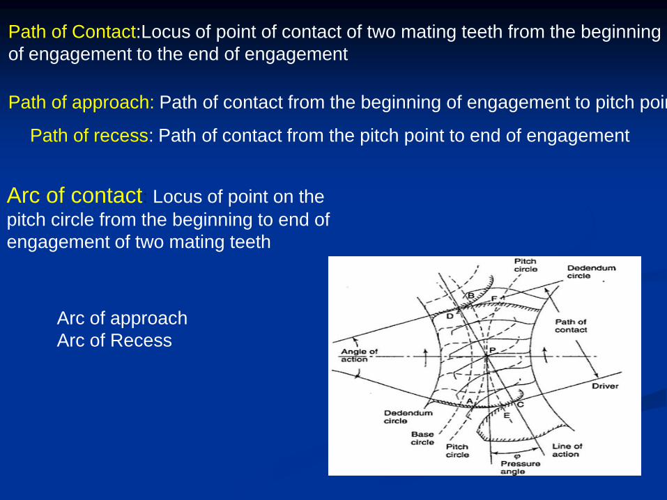
Path of Contact:Locus of point of contact of two mating teeth from the beginning
of engagement to the end of engagement
Path of approach: Path of contact from the beginning of engagement to pitch point
Path of recess: Path of contact from the pitch point to end of engagement
Arc of contact: Locus of point on the
pitch circle from the beginning to end of
engagement of two mating teeth
Arc of approach
Arc of Recess
Law of Gearing
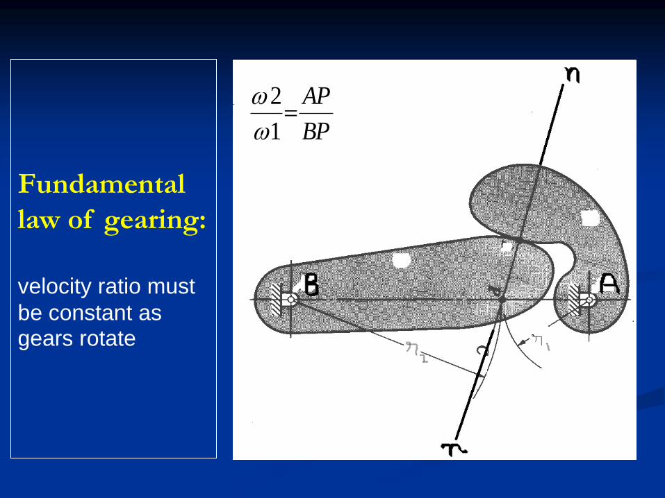
Fundamental
law of gearing:
velocity ratio must
be constant as gears rotate
BP
AP
1
2
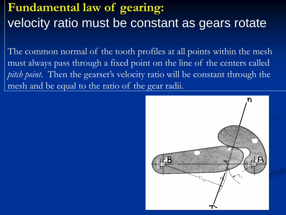
Fundamental law of gearing:
velocity ratio must be constant as gears rotate The common normal of the tooth profiles at all points within the mesh
must always pass through a fixed point on the line of the centers called
pitch point. Then the gearset’s velocity ratio will be constant through the
mesh and be equal to the ratio of the gear radii.
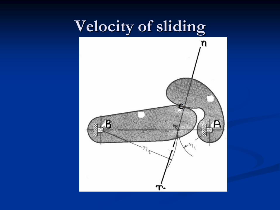
Velocity of sliding
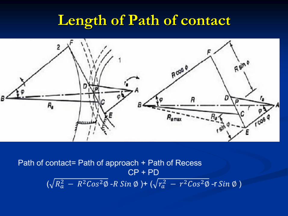
Length of Path of contact
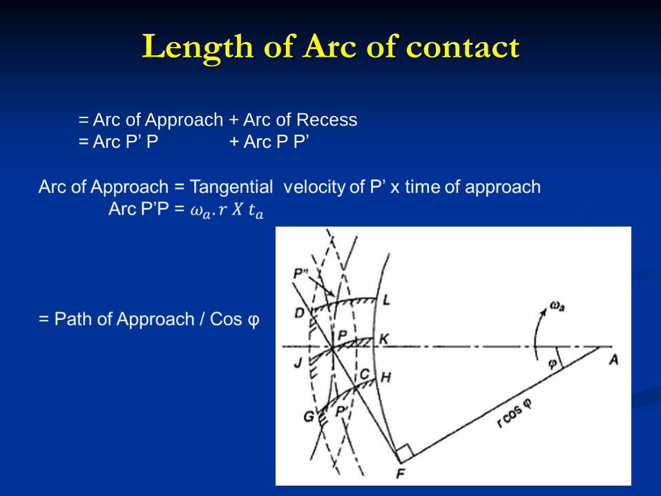
Length of Arc of contact
= Arc of Approach + Arc of Recess
= Arc P’ P + Arc P P’

Number of pairs of teeth in contact(Contact Ratio)
= Length of Arc of Contact
-------------------------------------
Circular Pitch
Contact Ratio must be greater than 1
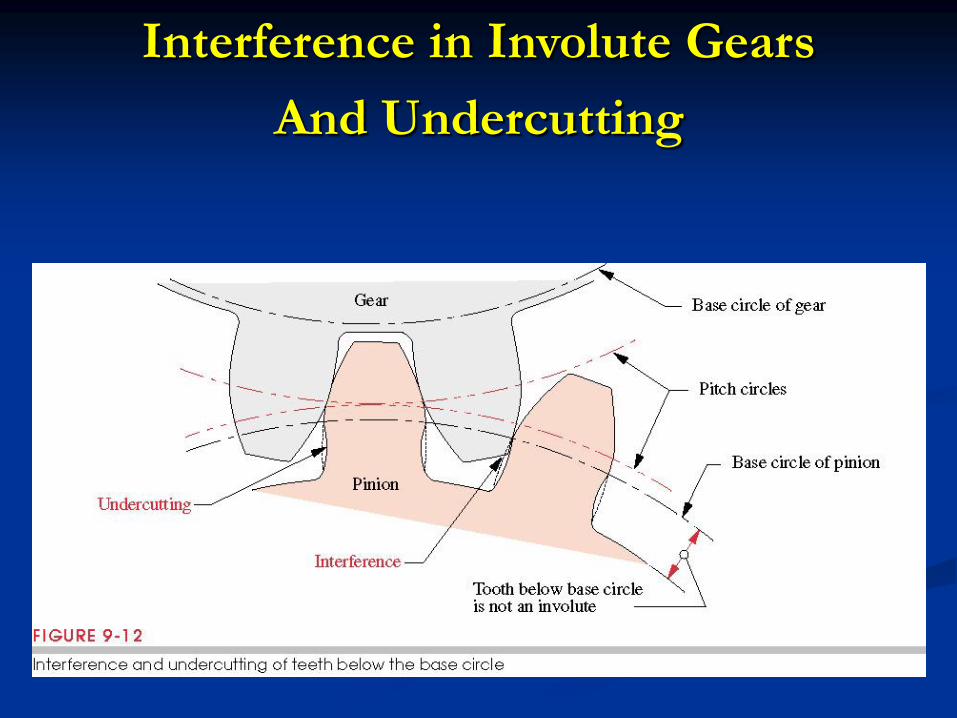
Interference in Involute Gears
And Undercutting
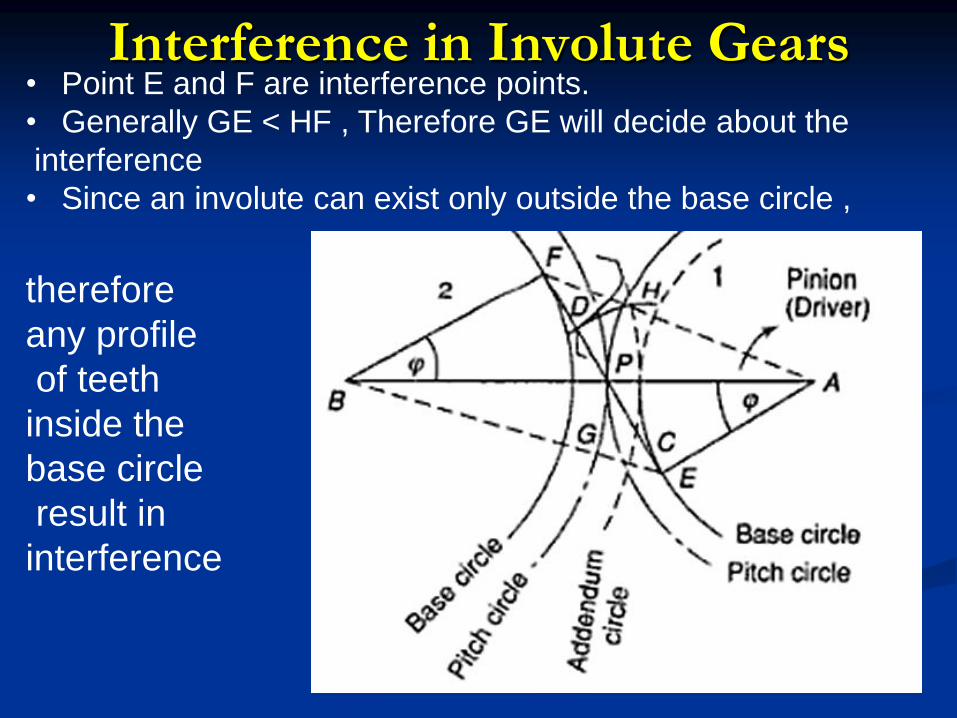
Interference in Involute Gears • Point E and F are interference points.
• Generally GE < HF , Therefore GE will decide about the
interference
• Since an involute can exist only outside the base circle ,
therefore
any profile
of teeth
inside the
base circle
result in
interference
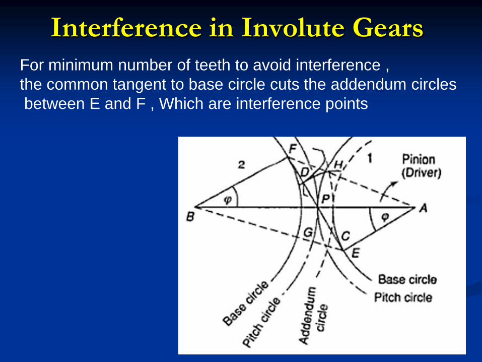
Interference in Involute Gears For minimum number of teeth to avoid interference ,
the common tangent to base circle cuts the addendum circles
between E and F , Which are interference points
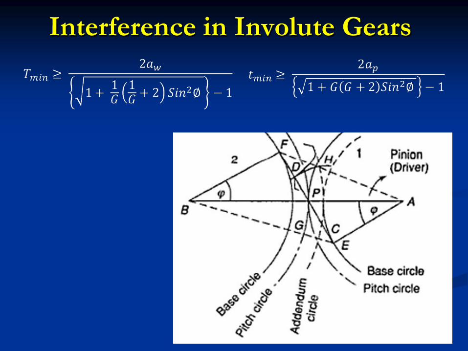
Interference in Involute Gears
Gear Review
What is a gear?
Name 4 different types of gears.
What is torque and rpm?
What is diametral pitch & how is it shown?
List 10 places where gears are used.
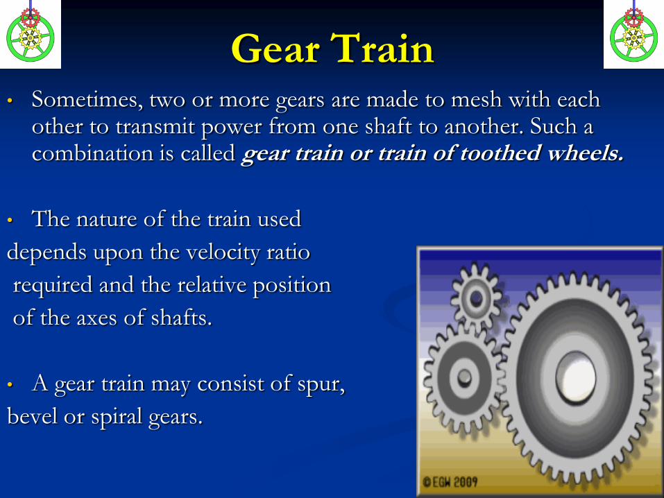
Gear Train • Sometimes, two or more gears are made to mesh with each
other to transmit power from one shaft to another. Such a combination is called gear train or train of toothed wheels.
• The nature of the train used
depends upon the velocity ratio
required and the relative position
of the axes of shafts.
• A gear train may consist of spur,
bevel or spiral gears.
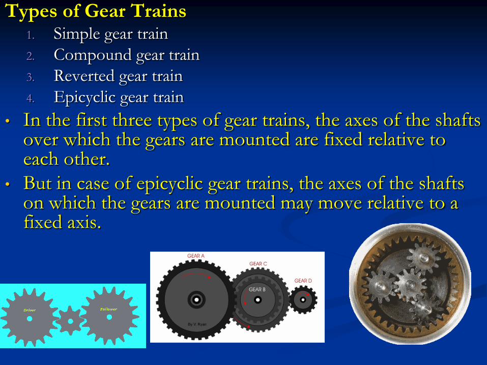
Types of Gear Trains 1. Simple gear train
2. Compound gear train
3. Reverted gear train
4. Epicyclic gear train
• In the first three types of gear trains, the axes of the shafts over which the gears are mounted are fixed relative to each other.
• But in case of epicyclic gear trains, the axes of the shafts on which the gears are mounted may move relative to a fixed axis.
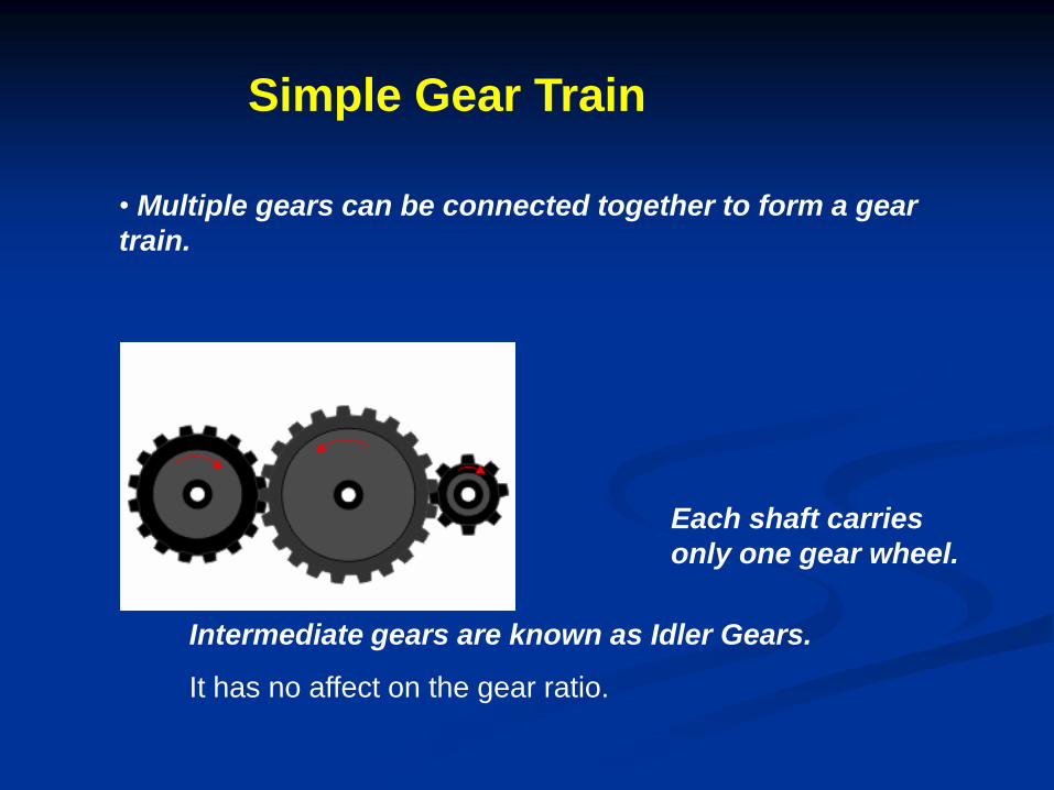
• Multiple gears can be connected together to form a gear
train.
Simple Gear Train
Each shaft carries
only one gear wheel.
Intermediate gears are known as Idler Gears.
It has no affect on the gear ratio.
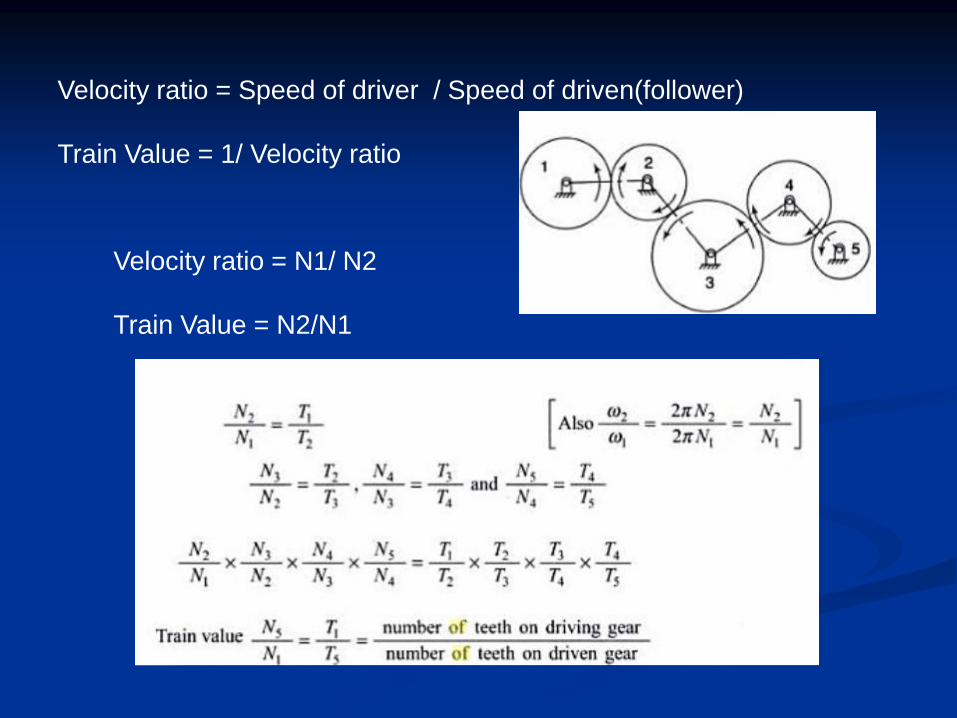
Velocity ratio = Speed of driver / Speed of driven(follower)
Train Value = 1/ Velocity ratio
Velocity ratio = N1/ N2
Train Value = N2/N1
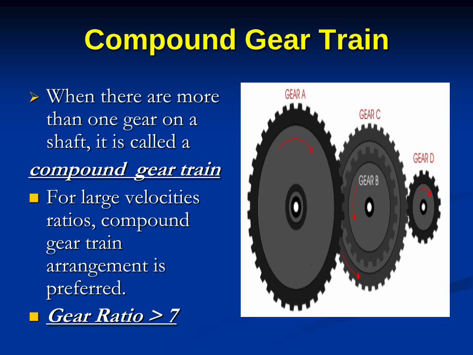
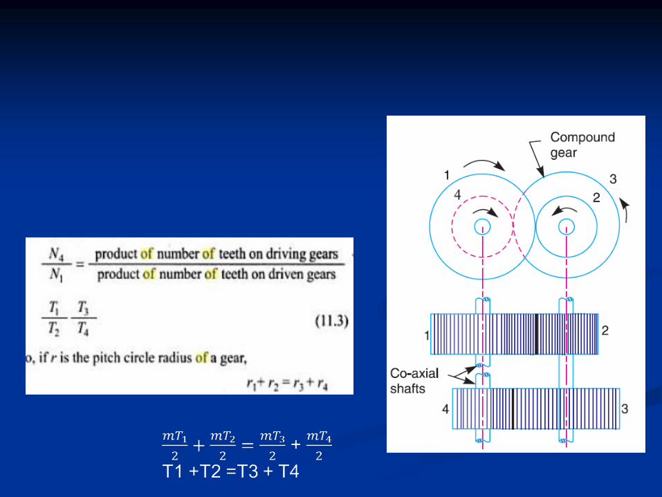
Compound Gear Train
When there are more than one gear on a shaft, it is called a
compound gear train
For large velocities ratios, compound gear train arrangement is preferred.
Gear Ratio > 7
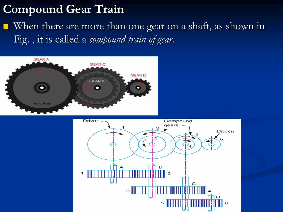
Compound Gear Train
When there are more than one gear on a shaft, as shown in
Fig. , it is called a compound train of gear.
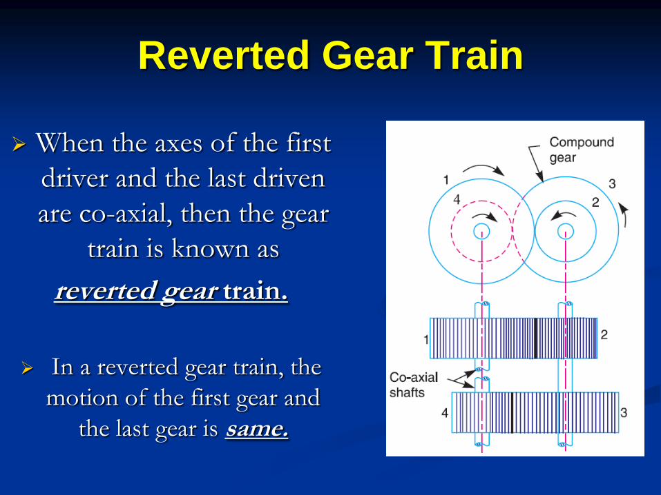
Reverted Gear Train
When the axes of the first
driver and the last driven
are co-axial, then the gear
train is known as
reverted gear train.
In a reverted gear train, the
motion of the first gear and
the last gear is same.
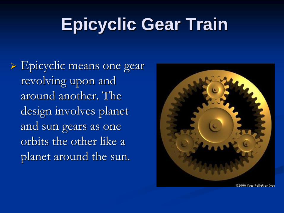
Epicyclic Gear Train
Epicyclic means one gear
revolving upon and
around another. The
design involves planet
and sun gears as one
orbits the other like a
planet around the sun.
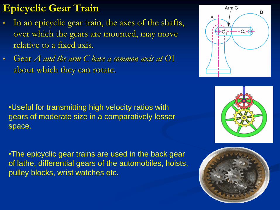
Epicyclic Gear Train
• In an epicyclic gear train, the axes of the shafts,
over which the gears are mounted, may move
relative to a fixed axis.
• Gear A and the arm C have a common axis at O1
about which they can rotate.
•Useful for transmitting high velocity ratios with
gears of moderate size in a comparatively lesser
space.
•The epicyclic gear trains are used in the back gear
of lathe, differential gears of the automobiles, hoists,
pulley blocks, wrist watches etc.
Velocity ratio of epicyclic gear
train
velocity ratio;
velocity ratio of epicyclic gear train is the ratio of the speed
of the driver to the speed of the driven or follower.
The following two methods may be used for finding out the
velocity ratio of an epicyclic gear train.
1.Tabular method
2. Algebraic method
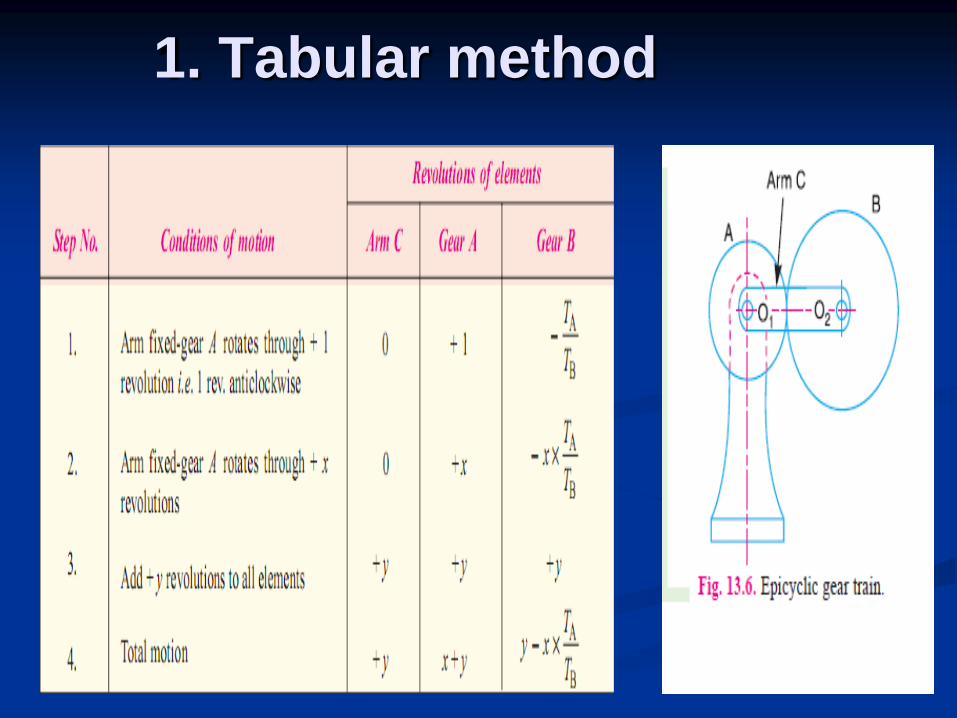
1. Tabular method
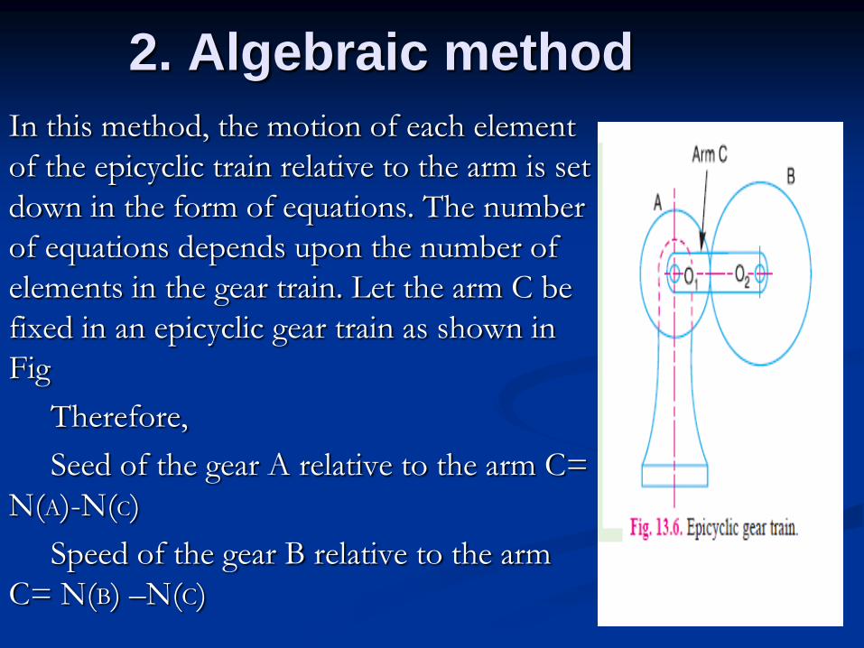
2. Algebraic method
In this method, the motion of each element
of the epicyclic train relative to the arm is set
down in the form of equations. The number
of equations depends upon the number of
elements in the gear train. Let the arm C be
fixed in an epicyclic gear train as shown in
Fig
Therefore,
Seed of the gear A relative to the arm C=
N(A)-N(C)
Speed of the gear B relative to the arm
C= N(B) –N(C)
ADVANTAGES of Simple Gear Train
to connect gears where a large center distance
is required
to obtain desired direction of motion of the
driven gear ( CW or CCW)
to obtain high speed ratio
ADVANTAGES of Compound
Gear Train
A much larger speed reduction from the
first shaft to the last shaft can be obtained
with small gear.
If a simple gear trains used to give a large
speed reduction, the last gear has to be very
large.
Advantages of
Riverted Gear Train
The reverted gear trains are used in automotive
transmissions, lathe back gears, industrial speed
reducers, and in clocks (where the minute and hour
hand shafts are co-axial).
YouTube Gear Animations:
Speed Reducers:
http://www.youtube.com/watch?v=7LReoWPg_pM&feature=related
http://www.youtube.com/watch?v=1_jbZVBXjWc&feature=related
Automotive Differential:
http://www.youtube.com/watch?v=iBLE0_Sjqw4&feature=related
Manual Transmission:
http://www.youtube.com/watch?v=MBmLJCeGu7o&feature=related
Gear Cutting:
http://www.youtube.com/watch?v=fps0OR1eF_s&feature=related
http://www.youtube.com/watch?v=xF9CjluRFJ4&feature=related