Kinematics Inverse Kinematic & Differential Kinematicsglobex.coe.pku.edu.cn › file › upload ›...
62
Kinematics – Inverse Kinematic & Differential Kinematics Centre for Robotics Research – School of Natural and Mathematical Sciences – King’s College London
Transcript of Kinematics Inverse Kinematic & Differential Kinematicsglobex.coe.pku.edu.cn › file › upload ›...

Kinematics – Inverse Kinematic
& Differential Kinematics
Centre for Robotics Research – School of Natural and Mathematical Sciences – King’s College London

Robotic Endovascular Interventions – Hamlyn Workshop 23 June 20152 Peking University Globex 20182
Introduction – Inverse and Forward Kinematics
Inverse
Forward

Robotic Endovascular Interventions – Hamlyn Workshop 23 June 20153 Peking University Globex 20183
Introduction – Inverse Kinematics

Robotic Endovascular Interventions – Hamlyn Workshop 23 June 20154 Peking University Globex 20184
Introduction – Inverse Kinematics
Robot Kinematic Control
Inverse kinematic
Actuation
Orientation θ, position pdesired force
Joint variables( ሶθ, ሶd)

Robotic Endovascular Interventions – Hamlyn Workshop 23 June 20155 Peking University Globex 20185
Analytical Inverse kinematic
• The inverse kinematics problem consists of the determination of the joint variables
corresponding to a given end-effector position and orientation.
• Analytical inverse kinematic equation can be derived from forward kinematic equa
tion using trigonometric identities
Trigonometric identities
𝑠𝑖𝑛2(𝜃1)+𝑐𝑜𝑠2 𝜃1 = 1
𝑡𝑎𝑛2 𝜃1 + 1 = 𝑠𝑒𝑐2 𝜃1
𝑐𝑜𝑡2 𝜃1 + 1 = 𝑐𝑠𝑐2 𝜃1
sin(𝜃1 ± 𝜃2) = sin 𝜃1 cos(𝜃2) ± cos 𝜃1 sin(𝜃2)
cos(𝜃1 ± 𝜃2) = 𝑐𝑜𝑠 𝜃1 cos(𝜃2) ∓ sin 𝜃1 sin(𝜃2)
sin(2𝜃1) = 2sin 𝜃1 𝑐𝑜𝑠 𝜃1
cos(2𝜃1) = 𝑐𝑜𝑠2 𝜃1 -𝑠𝑖𝑛2 𝜃1
= 2𝑐𝑜𝑠2 𝜃1 − 1
= 1 − 2𝑠𝑖𝑛2 𝜃1
Robotic Endovascular Interventions – Hamlyn Workshop 23 June 20156 Peking University Globex 20186
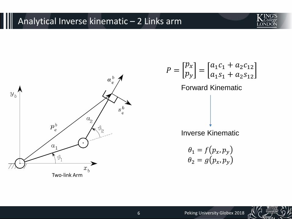
Analytical Inverse kinematic – 2 Links arm
Two-link Arm
𝑃 =𝑝𝑥𝑝𝑦
=𝑎1𝑐1 + 𝑎2𝑐12𝑎1𝑠1 + 𝑎2𝑠12
Inverse Kinematic
Forward Kinematic
𝜃1 = 𝑓 𝑝𝑥, 𝑝𝑦𝜃2 = 𝑔 𝑝𝑥, 𝑝𝑦

Robotic Endovascular Interventions – Hamlyn Workshop 23 June 20157 Peking University Globex 20187
Analytical Inverse kinematic – 2 Links arm
𝑃 =𝑝𝑥𝑝𝑦
=𝑎1𝑐1 + 𝑎2𝑐12𝑎1𝑠1 + 𝑎2𝑠12
𝑝𝑥 = 𝑎1𝑐1 + 𝑎2𝑐12𝑝𝑦 = 𝑎1𝑠1 + 𝑎2𝑆12
𝑝𝑥2 = 𝑎1
2𝑐12 + 𝑎2
2𝑐122 + 2𝑎1𝑎2𝑐1𝑐12 (1)
𝑝𝑦2 = 𝑎1
2𝑠12 + 𝑎2
2𝑠122 + 2𝑎1𝑎2𝑠1𝑠12 (2)
(1)+(2) and apply Trigonometric equation
𝑝𝑥2 + 𝑝𝑦
2 = 𝑎12 + 𝑎2
2 + 2𝑎1𝑎2 cos −𝜃2
cos(𝜃2) =𝑝𝑥2 + 𝑝𝑦
2 − 𝑎12 − 𝑎2
2
2𝑎1𝑎2
Squaring and summing of the equations

Robotic Endovascular Interventions – Hamlyn Workshop 23 June 20158 Peking University Globex 20188
Analytical Inverse kinematic – 2 Links arm
cos(𝜃2) =𝑝𝑥2 + 𝑝𝑦
2 − 𝑎12 − 𝑎2
2
2𝑎1𝑎2
sin(𝜃2) = ± 1 − cos(𝜃2)
Two possible solutions
𝜃2 = 𝑎𝑡𝑎𝑛2(𝑠𝑖𝑛𝜃2, 𝑐𝑜𝑠𝜃2)
Robotic Endovascular Interventions – Hamlyn Workshop 23 June 20159 Peking University Globex 20189
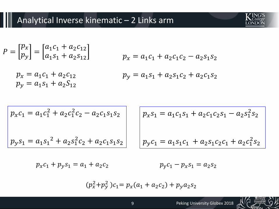
Analytical Inverse kinematic – 2 Links arm
𝑃 =𝑝𝑥𝑝𝑦
=𝑎1𝑐1 + 𝑎2𝑐12𝑎1𝑠1 + 𝑎2𝑠12
𝑝𝑥 = 𝑎1𝑐1 + 𝑎2𝑐12𝑝𝑦 = 𝑎1𝑠1 + 𝑎2𝑆12
𝑝𝑥 = 𝑎1𝑐1 + 𝑎2𝑐1𝑐2 − 𝑎2𝑠1𝑠2
𝑝𝑦 = 𝑎1𝑠1 + 𝑎2𝑠1𝑐2 + 𝑎2𝑐1𝑠2
𝑝𝑥𝑐1 = 𝑎1𝑐12 + 𝑎2𝑐1
2𝑐2 − 𝑎2𝑐1𝑠1𝑠2
𝑝𝑦𝑠1 = 𝑎1𝑠12 + 𝑎2𝑠1
2𝑐2 + 𝑎2𝑐1𝑠1𝑠2
𝑝𝑥𝑠1 = 𝑎1𝑐1𝑠1 + 𝑎2𝑐1𝑐2𝑠1 − 𝑎2𝑠12𝑠2
𝑝𝑦𝑐1 = 𝑎1𝑠1𝑐1 + 𝑎2𝑠1𝑐2𝑐1 + 𝑎2𝑐12𝑠2
𝑝𝑥𝑐1 + 𝑝𝑦𝑠1 = 𝑎1 + 𝑎2𝑐2 𝑝y𝑐1 − 𝑝𝑥𝑠1 = 𝑎2𝑠2
(𝑝𝑥2+𝑝𝑦
2 )𝑐1= 𝑝𝑥(𝑎1 + 𝑎2𝑐2) + 𝑝𝑦𝑎2𝑠2

Robotic Endovascular Interventions – Hamlyn Workshop 23 June 201510 Peking University Globex 201810
Analytical Inverse kinematic – 2 Links arm
𝑝𝑥𝑐1 + 𝑝𝑦𝑠1 = 𝑎1 + 𝑎2𝑐2 (1)
𝑝y𝑐1 − 𝑝𝑥𝑠1 = 𝑎2𝑠2 (2)
(𝑝𝑥2+𝑝𝑦
2 )𝑐1= 𝑝𝑥(𝑎1 + 𝑎2𝑐2) + 𝑝𝑦𝑎2𝑠2
Multiply px on both sides of eq.1 + multiply py on both sides of eq.2
cos(𝜃1) =(𝑝𝑥(𝑎1 + 𝑎2𝑐2) + 𝑝𝑦𝑎2𝑠2)
𝑝𝑥2 + 𝑝𝑦
2

Robotic Endovascular Interventions – Hamlyn Workshop 23 June 201511 Peking University Globex 201811
Analytical Inverse kinematic – 2 Links arm
𝑝𝑥𝑐1 + 𝑝𝑦𝑠1 = 𝑎1 + 𝑎2𝑐2 (1)
𝑝y𝑐1 − 𝑝𝑥𝑠1 = 𝑎2𝑠2 (2)
(𝑝𝑥2+𝑝𝑦
2 )𝑠1= 𝑝𝑦(𝑎1 + 𝑎2𝑐2) − 𝑝𝑥𝑎2𝑠2
Multiply py on both sides of eq.1 - multiply px on both sides of eq.2
sin(𝜃1) =𝑝𝑦(𝑎1 + 𝑎2𝑐2) − 𝑝𝑥𝑎2𝑠2)
𝑝𝑥2 + 𝑝𝑦
2

Robotic Endovascular Interventions – Hamlyn Workshop 23 June 201512 Peking University Globex 201812
𝜃1 = 𝑎𝑡𝑎𝑛2(𝑠𝑖𝑛𝜃1, 𝑐𝑜𝑠𝜃1)
unique solution
Analytical Inverse kinematic – 2 Links arm
cos(𝜃1) =(𝑝𝑥(𝑎1 + 𝑎2𝑐2) + 𝑝𝑦𝑎2𝑠2)
𝑝𝑥2 + 𝑝𝑦
2
sin(𝜃1) =𝑝𝑦(𝑎1 + 𝑎2𝑐2) − 𝑝𝑥𝑎2𝑠2)
𝑝𝑥2 + 𝑝𝑦
2

Robotic Endovascular Interventions – Hamlyn Workshop 23 June 201513 Peking University Globex 201813
Two-link Arm
𝑃 =𝑝𝑥𝑝𝑦
=𝑎1𝑐1 + 𝑎2𝑐12𝑎1𝑠1 + 𝑎2𝑠12
Inverse Kinematic
Forward Kinematic
𝜃2 = cos−1𝑝𝑥2 + 𝑝𝑦
2 − 𝑎12 − 𝑎2
2
2𝑎1𝑎2
𝜃1 = cos−1𝑝𝑥(𝑎1 + 𝑎2𝑐2) + 𝑝𝑦𝑎2𝑠2
𝑝𝑥2 + 𝑝𝑦
2
Analytical Inverse kinematic – 2 Links arm

Robotic Endovascular Interventions – Hamlyn Workshop 23 June 201514 Peking University Globex 201814
Analytical Inverse kinematic – 3 Links Arm
A first algebraic solution technique is
illustrated below.
Using the forward kinematic equation of
two-link arm.
which describe the position of point W

Robotic Endovascular Interventions – Hamlyn Workshop 23 June 201515 Peking University Globex 201815
Analytical Inverse kinematic– 3 Links Arm
Squaring and summing of the equations

Robotic Endovascular Interventions – Hamlyn Workshop 23 June 201516 Peking University Globex 201816
Analytical Inverse kinematic– 3 Links Arm
Hence, the angle 𝜃2 can be computed as

Robotic Endovascular Interventions – Hamlyn Workshop 23 June 201517 Peking University Globex 201817
Analytical Inverse kinematic– 3 Links Arm
Substituting 𝜃2 into equations for 𝑃𝑤𝑥, 𝑎𝑛𝑑 𝑃𝑤𝑦
to find solutions of unknown 𝑠1 and 𝑐1
In analogy to the above, it is

Robotic Endovascular Interventions – Hamlyn Workshop 23 June 201518 Peking University Globex 201818
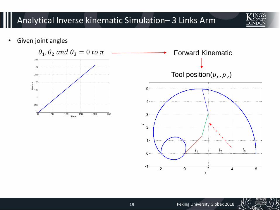
Analytical Inverse kinematic Simulation– 3 Links Arm
𝜃1, 𝜃2 𝑎𝑛𝑑 𝜃3 = 0 𝑡𝑜 𝜋 Forward Kinematic
𝑇𝑜𝑜𝑙 𝑜𝑟𝑖𝑒𝑛𝑡𝑎𝑡𝑖𝑜𝑛 (∅)
𝜃1 + 𝜃2 + 𝜃3 = ∅
3𝜋
Robotic Endovascular Interventions – Hamlyn Workshop 23 June 201519 Peking University Globex 201819
Analytical Inverse kinematic Simulation– 3 Links Arm
• Given joint angles
𝜃1, 𝜃2 𝑎𝑛𝑑 𝜃3 = 0 𝑡𝑜 𝜋
Tool position(𝑝𝑥, 𝑝𝑦)
𝑙1 𝑙2 𝑙3
Forward Kinematic

Robotic Endovascular Interventions – Hamlyn Workshop 23 June 201520 Peking University Globex 201820
Analytical Inverse kinematic Simulation– 3 Links Arm
• Given joint angles
Tool position(𝑝𝑥, 𝑝𝑦)
Inverse
Kinematic
𝑇𝑜𝑜𝑙 𝑜𝑟𝑖𝑒𝑛𝑡𝑎𝑡𝑖𝑜𝑛 (∅)
Thus, if inverse kinematic is correct, given 𝜃 = output 𝜃 of IK
Given 𝜃 FK 𝑝𝑥, 𝑝𝑦 𝑎𝑛𝑑 ∅ IK Output 𝜃
=
Robotic Endovascular Interventions – Hamlyn Workshop 23 June 201521 Peking University Globex 201821
Programming exercise in class
Analytical Inverse kinematic Simulation– 3 Links Arm
IKexercise.zip
inverse_kinematic_analytical_q

Robotic Endovascular Interventions – Hamlyn Workshop 23 June 201522 Peking University Globex 201822
Analytical Inverse kinematic Simulation
• Given joint angles
Given 𝜃 Output 𝜃
𝜃1
𝜃2 𝜃3
𝜃1
𝜃2 𝜃3
=

Robotic Endovascular Interventions – Hamlyn Workshop 23 June 201523 Peking University Globex 201823
Analytical Inverse kinematic problem
• The equations to solve are in general nonlinear, and thus it is not always
possible to find a closed-form solution.
• Multiple solutions may exist.
• Infinite solutions may exist, e.g., in the case of a kinematic redundant
manipulator.
• There might be no admissible solutions, in view of the manipulator kinematic
structure.
• Accurate and most time efficient IK

Robotic Endovascular Interventions – Hamlyn Workshop 23 June 201524 Peking University Globex 201824
Derivative
Differential Kinematics : Math essentials
h= Δx
f(x)
Robotic Endovascular Interventions – Hamlyn Workshop 23 June 201525 Peking University Globex 201825
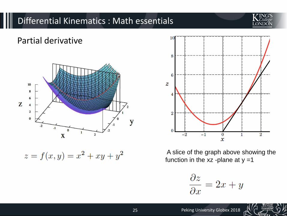
Partial derivative
Differential Kinematics : Math essentials
A slice of the graph above showing the
function in the xz -plane at y =1

Robotic Endovascular Interventions – Hamlyn Workshop 23 June 201526 Peking University Globex 201826
Differential Kinematics : Math essentials
Cross product

Robotic Endovascular Interventions – Hamlyn Workshop 23 June 201527 Peking University Globex 201827
Differential Kinematic
square matrix(𝑟 × 𝑛)
• Differential kinematics gives the relationship between the joint velocities and the corresponding end-effector linear and angular velocity.
• This mapping is described by a Jacobian(J) matrix, which depends on the manipulatorconfiguration.
End-effector velocity(𝑟 × 1)
Joint velocity(𝑛 × 1)
Geometric Jacobian matrix
The Jacobian matrix (J) can be partitioned into the (3 × 1) column vectors 𝐽𝑃𝑖 and 𝐽𝑂𝑖 as

Robotic Endovascular Interventions – Hamlyn Workshop 23 June 201528 Peking University Globex 201828
Differential Kinematic
square matrix(𝑟 × 𝑛)
• Differential kinematics gives the relationship between the joint velocities and the corresponding end-effector linear and angular velocity.
• This mapping is described by a Jacobian(J) matrix, which depends on the manipulator configuration.
End-effector velocity(𝑟 × 1)
Joint velocity(𝑛 × 1)
Analytical Jacobian matrix

Robotic Endovascular Interventions – Hamlyn Workshop 23 June 201529 Peking University Globex 201829
Differential Kinematic
square matrix(𝑟 × 𝑛)
The Jacobian matrix J is one of the most important tools for finding singularities, a
nalyzing redundancy, determining inverse kinematics equation, and describing velocity and force manipulability ellipsoids.
• Differential kinematics gives the relationship between the joint velocities and the corresponding end-effector linear and angular velocity.
• This mapping is described by a Jacobian(J) matrix, which depends on the manipulator configuration.
End-effector velocity(𝑟 × 1)
Joint velocity(𝑛 × 1)
Robotic Endovascular Interventions – Hamlyn Workshop 23 June 201530 Peking University Globex 201830
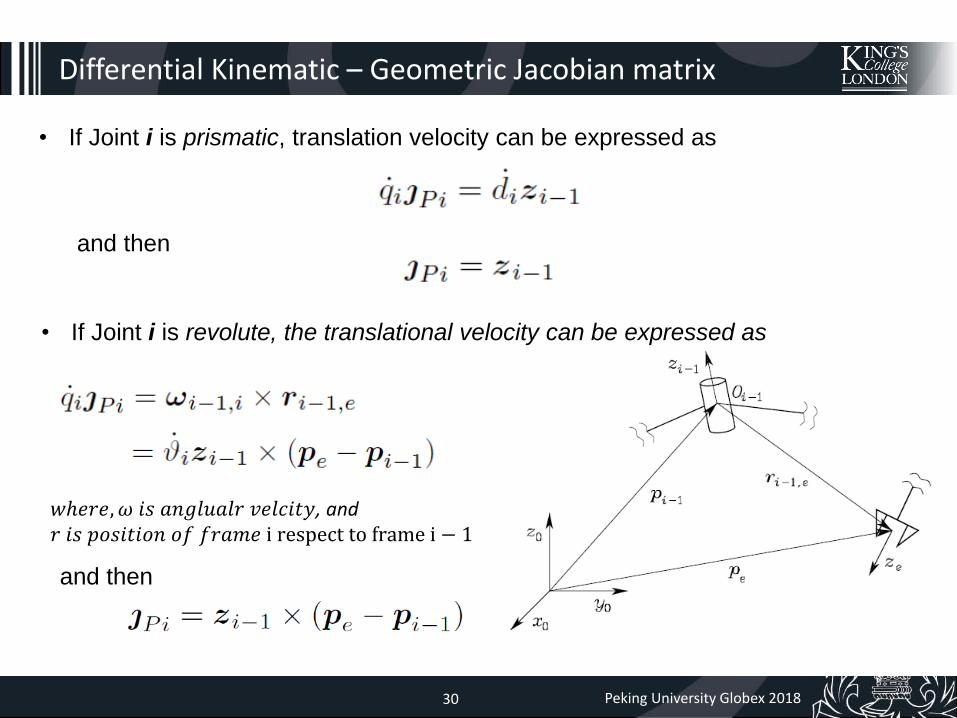
Differential Kinematic – Geometric Jacobian matrix
• If Joint i is prismatic, translation velocity can be expressed as
and then
• If Joint i is revolute, the translational velocity can be expressed as
𝑤ℎ𝑒𝑟𝑒, 𝜔 𝑖𝑠 𝑎𝑛𝑔𝑙𝑢𝑎𝑙𝑟 𝑣𝑒𝑙𝑐𝑖𝑡𝑦, and𝑟 𝑖𝑠 𝑝𝑜𝑠𝑖𝑡𝑖𝑜𝑛 𝑜𝑓 𝑓𝑟𝑎𝑚𝑒 i respect to frame i − 1
and then

Robotic Endovascular Interventions – Hamlyn Workshop 23 June 201531 Peking University Globex 201831
Differential Kinematic – Geometric Jacobian matrix
Pe
Pi-1
P0
P1
𝜃𝑖
𝜃2
𝜃1
assuming the rest joints are locked

Robotic Endovascular Interventions – Hamlyn Workshop 23 June 201532 Peking University Globex 201832
Differential Kinematic – Geometric Jacobian matrix
For position components in the Jacobian matrix(𝐽𝑃𝑖)
• For the contribution to the linear velocity, the time derivative of 𝒑𝒆(𝒒)can be written as
• ሶ𝑝𝑒 can be obtained as the sum of the terms ሶ𝑞𝑖𝐽𝑃𝑖
• Each term represents the contribution of the velocity of single Joint i to the end-effector linear velocity when all the other joints are still.
• Therefore, by distinguishing the case of a prismatic joint (𝑞𝑖 = 𝑑𝑖) from the case of a revolute joint (𝑞𝑖 = 𝜃), it is:

Robotic Endovascular Interventions – Hamlyn Workshop 23 June 201533 Peking University Globex 201833
Differential Kinematic – Geometric Jacobian matrix
ሶ𝑞1ሶ𝑞2⋮ሶ𝑞𝑛
ሶ𝑝𝑒 = 𝑱𝑃1 𝑱𝑃2 … 𝑱𝑃𝑛
For position components in the Jacobian matrix(𝐽𝑃𝑖)

Robotic Endovascular Interventions – Hamlyn Workshop 23 June 201534 Peking University Globex 201834
Differential Kinematic – Geometric Jacobian matrix
For orientation components in the Jacobian matrix(𝐽0𝑖)
• If Joint i is prismatic,
• If Joint i is revolute

Robotic Endovascular Interventions – Hamlyn Workshop 23 June 201535 Peking University Globex 201835
Differential Kinematic – Geometric Jacobian matrix
For orientation components in the Jacobian matrix(𝐽0𝑖)
• For the contribution to the angular velocity
ሶ𝑞1ሶ𝑞2⋮ሶ𝑞𝑛
𝜔𝑒 = 𝑱𝑂1 𝑱𝑂2 … 𝑱𝑂𝑛

Robotic Endovascular Interventions – Hamlyn Workshop 23 June 201536 Peking University Globex 201836
Differential Kinematic – Geometric Jacobian matrix
• The Jacobian matrix (J) can be partitioned into the (3 × 1) column vectors 𝐽𝑃𝑖 and 𝐽𝑂𝑖 as
For a prismatic joint
For a revolute joint
=
=

Robotic Endovascular Interventions – Hamlyn Workshop 23 June 201537 Peking University Globex 201837
Differential Kinematic – Geometric Jacobian matrix
• The Jacobian matrix (J) can be partitioned into the (3 × 1) column vectors 𝐽𝑃𝑖 and 𝐽𝑂𝑖 as
• 𝑧𝑖−1 is given by the rotation of z-axis unit vector
• 𝑃𝑒 is given by the position vector in the transformation matrix 𝑇𝑒0
𝑃𝑒 = 𝑇10(𝑞1)⋯𝑇𝑛
𝑛−1(𝑞𝑛)𝑃𝑜
• 𝑃𝑖−1 is given by the position vector in the transformation matrix 𝑇𝑖−10
𝑃𝑖−1 = 𝑇10(𝑞1)⋯𝑇𝑛−1
𝑛−2(𝑞𝑖−1)𝑃𝑜

Robotic Endovascular Interventions – Hamlyn Workshop 23 June 201538 Peking University Globex 201838
Differential Kinematic – Geometric Jacobian matrix
• 𝐸𝑥𝑎𝑚𝑝𝑙𝑒(𝑇ℎ𝑟𝑒𝑒 − 𝑙𝑖𝑛𝑘 𝑝𝑙𝑎𝑛𝑎𝑟 𝑎𝑟𝑚, 𝑙𝑖𝑛𝑘𝑠 𝑙𝑒𝑛𝑔𝑡ℎ 𝑎1, 𝑎2, 𝑎3)
𝐼𝑛 𝑡ℎ𝑖𝑠 𝑐𝑎𝑠𝑒, 𝑡ℎ𝑒 𝐽𝑎𝑐𝑜𝑏𝑖𝑎𝑛 𝑖𝑠
• 𝑃0, 𝑃1, 𝑃2 and 𝑃3 𝑎𝑟𝑒 𝑎𝑠
𝑃0
𝑃1
𝑃2
𝑃3

Robotic Endovascular Interventions – Hamlyn Workshop 23 June 201539 Peking University Globex 201839
Differential Kinematic – Geometric Jacobian matrix
• 𝐸𝑥𝑎𝑚𝑝𝑙𝑒(𝑇ℎ𝑟𝑒𝑒 − 𝑙𝑖𝑛𝑘 𝑝𝑙𝑎𝑛𝑎𝑟 𝑎𝑟𝑚)
• 𝑧0, 𝑧1, and 𝑧2 𝑎𝑟𝑒 𝑎𝑠
• 𝑧0 × (𝑃3 − 𝑃0)• 𝑍 ×= 𝑍 ×
𝑧0 × (𝑃3 − 𝑃0)
=0 −1 01 0 00 0 0
𝑎1𝑐1 + 𝑎2𝑐12 + 𝑎3𝑐123𝑎1𝑠1 + 𝑎2𝑠12 + 𝑎3𝑠123
0
=−𝑎1𝑠1 − 𝑎2𝑠12 − 𝑎3𝑠123𝑎1𝑐1 + 𝑎2𝑐12 + 𝑎3𝑐123
0
𝑃0
𝑃1
𝑃2
𝑃3

Robotic Endovascular Interventions – Hamlyn Workshop 23 June 201540 Peking University Globex 201840
Differential Kinematic – Geometric Jacobian matrix
• 𝐸𝑥𝑎𝑚𝑝𝑙𝑒(𝑇ℎ𝑟𝑒𝑒 − 𝑙𝑖𝑛𝑘 𝑝𝑙𝑎𝑛𝑎𝑟 𝑎𝑟𝑚)
• 𝑇ℎ𝑢𝑠, 𝑡ℎ𝑒 𝑗𝑎𝑐𝑜𝑏𝑖𝑎𝑛 𝑚𝑎𝑡𝑟𝑖𝑥 𝑜𝑓 𝑡ℎ𝑟𝑒𝑒 − 𝑙𝑖𝑛𝑘 𝑎𝑟𝑚 𝑖𝑠
JO1
JP1
𝑃0
𝑃1
𝑃2
𝑃3

Robotic Endovascular Interventions – Hamlyn Workshop 23 June 201541 Peking University Globex 201841
𝑃0
𝑃1
𝑃2
𝑃3
Differential Kinematic – Geometric Jacobian matrix
• 𝐸𝑥𝑎𝑚𝑝𝑙𝑒(𝑇ℎ𝑟𝑒𝑒 − 𝑙𝑖𝑛𝑘 𝑝𝑙𝑎𝑛𝑎𝑟 𝑎𝑟𝑚)
• 𝑧0, 𝑧1, and 𝑧2 𝑎𝑟𝑒 𝑎𝑠
• 𝑇ℎ𝑢𝑠, 𝑡ℎ𝑒 𝑗𝑎𝑐𝑜𝑏𝑖𝑎𝑛 𝑚𝑎𝑡𝑟𝑖𝑥 𝑜𝑓 𝑡ℎ𝑟𝑒𝑒 − 𝑙𝑖𝑛𝑘 𝑎𝑟𝑚 𝑖𝑠
• 𝐼𝑓 𝑜𝑟𝑖𝑒𝑛𝑡𝑎𝑡𝑖𝑜𝑛 𝑖𝑠 𝑛𝑜𝑡 𝑐𝑜𝑛𝑠𝑖𝑑𝑒𝑟𝑒𝑑, 𝑡ℎ𝑒 𝐽 𝑖𝑠

Robotic Endovascular Interventions – Hamlyn Workshop 23 June 201542 Peking University Globex 201842
Differential Kinematic – Analytical Jacobian matrix
Analytical Jacobian matrix is derived via differentiation of the forward kinematics to the
actuator vector
• 𝐿𝑒𝑡′𝑠 ሶ𝑃e 𝑖𝑠 𝑡ℎ𝑒 𝑡𝑖𝑚𝑒 𝑑𝑒𝑟𝑖𝑣𝑎𝑡𝑖𝑣𝑒 𝑜𝑓 𝑡ℎ𝑒 𝑡𝑟𝑎𝑛𝑠𝑙𝑎𝑡𝑖𝑜𝑛𝑎𝑙 𝑜𝑓 𝑡ℎ𝑒 𝑒𝑛𝑑 𝑒𝑓𝑓𝑒𝑐𝑡 𝑓𝑟𝑎𝑚𝑒.
• 𝐿𝑒𝑡′𝑠 𝜙e 𝑖𝑠 𝑡ℎ𝑒 𝑜𝑟𝑖𝑒𝑛𝑡𝑎𝑡𝑖𝑜𝑛, ሶ𝜙𝑒 𝜔𝑒 𝑖𝑠 𝑡ℎ𝑒 𝑎𝑛𝑔𝑢𝑙𝑎𝑟 𝑣𝑒𝑙𝑜𝑐𝑖𝑡𝑦.
• 𝑇ℎ𝑢𝑠.
ሶ𝜙𝑒 =𝜕𝜙e
𝜕𝒒ሶ𝒒 = 𝑱𝝓 𝒒 ሶ𝒒
𝜕𝒙e𝜕𝒒

Robotic Endovascular Interventions – Hamlyn Workshop 23 June 201543 Peking University Globex 201843
Differential Kinematic – Analytical Jacobian matrix
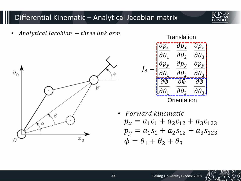
• 𝐴𝑛𝑎𝑙𝑦𝑡𝑖𝑐𝑎𝑙 𝐽𝑎𝑐𝑜𝑏𝑖𝑎𝑛 − 𝑡ℎ𝑟𝑒𝑒 𝑙𝑖𝑛𝑘 𝑎𝑟𝑚
• 𝐴𝑛𝑙𝑎𝑦𝑡𝑖𝑐𝑎𝑙 𝑗𝑎𝑐𝑜𝑏𝑖𝑎𝑛 𝑚𝑎𝑡𝑟𝑖𝑥 𝑓𝑜𝑟𝑚 𝑓𝑜𝑟𝑡ℎ𝑟𝑒𝑒 𝑙𝑖𝑛𝑘 𝑎𝑟𝑚 𝑖𝑠
𝐽𝐴 =
𝜕𝑝𝑥𝜕𝜃1
𝜕𝑝𝑥𝜕𝜃2
𝜕𝑝𝑥𝜕𝜃3
𝜕𝑝𝑦
𝜕𝜃1
𝜕𝑝𝑦
𝜕𝜃2
𝜕𝑝𝑦
𝜕𝜃3𝜕∅
𝜕𝜃1
𝜕∅
𝜕𝜃2
𝜕∅
𝜕𝜃3
Translation
Orientation
Robotic Endovascular Interventions – Hamlyn Workshop 23 June 201544 Peking University Globex 201844
Differential Kinematic – Analytical Jacobian matrix
• 𝐴𝑛𝑎𝑙𝑦𝑡𝑖𝑐𝑎𝑙 𝐽𝑎𝑐𝑜𝑏𝑖𝑎𝑛 − 𝑡ℎ𝑟𝑒𝑒 𝑙𝑖𝑛𝑘 𝑎𝑟𝑚
𝑝𝑥 = 𝑎1𝑐1 + 𝑎2𝑐12 + 𝑎3𝑐123𝑝𝑦 = 𝑎1𝑠1 + 𝑎2𝑠12 + 𝑎3𝑠123𝜙 = 𝜃1 + 𝜃2 + 𝜃3
• 𝐹𝑜𝑟𝑤𝑎𝑟𝑑 𝑘𝑖𝑛𝑒𝑚𝑎𝑡𝑖𝑐
𝐽𝐴 =
𝜕𝑝𝑥𝜕𝜃1
𝜕𝑝𝑥𝜕𝜃2
𝜕𝑝𝑥𝜕𝜃3
𝜕𝑝𝑦
𝜕𝜃1
𝜕𝑝𝑦
𝜕𝜃2
𝜕𝑝𝑦
𝜕𝜃3𝜕∅
𝜕𝜃1
𝜕∅
𝜕𝜃2
𝜕∅
𝜕𝜃3
Translation
Orientation

Robotic Endovascular Interventions – Hamlyn Workshop 23 June 201545 Peking University Globex 201845
Differential Kinematic – Analytical Jacobian matrix
• 𝐴𝑛𝑎𝑙𝑦𝑡𝑖𝑐𝑎𝑙 𝐽𝑎𝑐𝑜𝑏𝑖𝑎𝑛 − 𝑡ℎ𝑟𝑒𝑒 𝑙𝑖𝑛𝑘 𝑎𝑟𝑚
𝑝𝑥 = 𝑎1𝑐1 + 𝑎2𝑐12 + 𝑎3𝑐123
𝜕𝑝𝑥𝜕𝜃1
= −𝑎1𝑠1 −𝑎2 𝑠12 −𝑎3 𝑠123
𝜕𝑝𝑥𝜕𝜃2
= −𝑎2𝑠12 −𝑎3 𝑠123
𝜕𝑝𝑥𝜕𝜃3
= −𝑎3𝑠123
• Let’s differentiate with respect to 𝜃1, 𝜃2 𝑎𝑛𝑑 𝜃3
Robotic Endovascular Interventions – Hamlyn Workshop 23 June 201546 Peking University Globex 201846
Differential Kinematic – Analytical Jacobian matrix
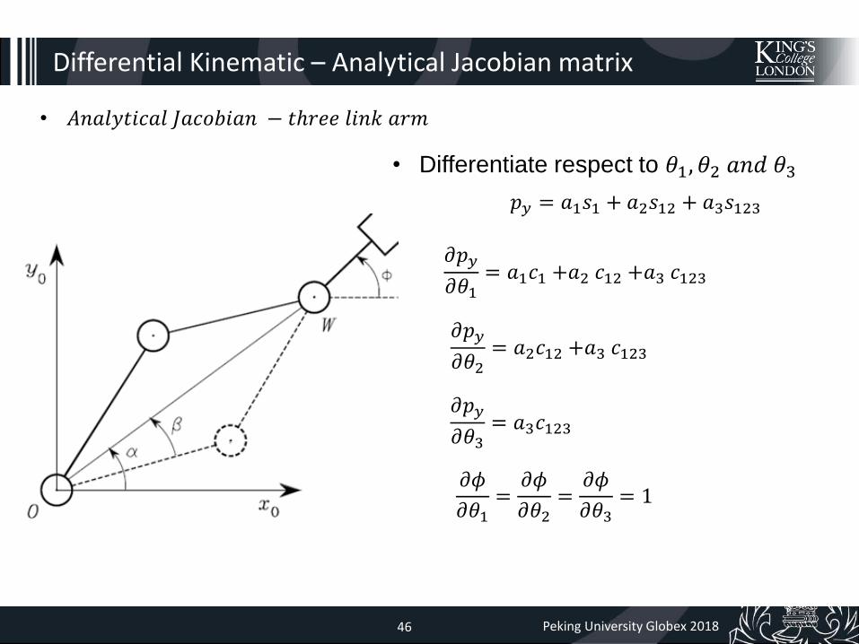
• 𝐴𝑛𝑎𝑙𝑦𝑡𝑖𝑐𝑎𝑙 𝐽𝑎𝑐𝑜𝑏𝑖𝑎𝑛 − 𝑡ℎ𝑟𝑒𝑒 𝑙𝑖𝑛𝑘 𝑎𝑟𝑚
• Differentiate respect to 𝜃1, 𝜃2 𝑎𝑛𝑑 𝜃3
𝑝𝑦 = 𝑎1𝑠1 + 𝑎2𝑠12 + 𝑎3𝑠123
𝜕𝑝𝑦
𝜕𝜃1= 𝑎1𝑐1 +𝑎2 𝑐12 +𝑎3 𝑐123
𝜕𝑝𝑦
𝜕𝜃2= 𝑎2𝑐12 +𝑎3 𝑐123
𝜕𝑝𝑦
𝜕𝜃3= 𝑎3𝑐123
𝜕𝜙
𝜕𝜃1=
𝜕𝜙
𝜕𝜃2=
𝜕𝜙
𝜕𝜃3= 1

Robotic Endovascular Interventions – Hamlyn Workshop 23 June 201547 Peking University Globex 201847
Differential Kinematic – Analytical Jacobian matrix
• Into the analytical Jacobian matrix
𝐽𝐴 =
𝜕𝑝𝑥𝜕𝜃1
𝜕𝑝𝑥𝜕𝜃2
𝜕𝑝𝑥𝜕𝜃3
𝜕𝑝𝑦
𝜕𝜃1
𝜕𝑝𝑦
𝜕𝜃2
𝜕𝑝𝑦
𝜕𝜃3𝜕∅
𝜕𝜃1
𝜕∅
𝜕𝜃2
𝜕∅
𝜕𝜃3
=−𝑎1𝑠1 −𝑎2 𝑠12 −𝑎3 𝑠123 −𝑎2𝑠12 −𝑎3 𝑠123 −𝑎3𝑠123𝑎1𝑐1 +𝑎2 𝑐12 +𝑎3 𝑐123 𝑎2𝑐12 +𝑎3 𝑐123 𝑎3𝑐123
1 1 1
Robotic Endovascular Interventions – Hamlyn Workshop 23 June 201548 Peking University Globex 201848
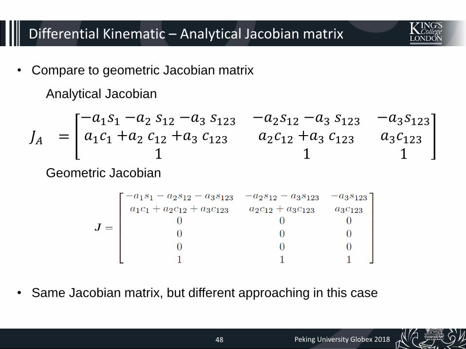
Differential Kinematic – Analytical Jacobian matrix
• Compare to geometric Jacobian matrix
𝐽𝐴 =−𝑎1𝑠1 −𝑎2 𝑠12 −𝑎3 𝑠123 −𝑎2𝑠12 −𝑎3 𝑠123 −𝑎3𝑠123𝑎1𝑐1 +𝑎2 𝑐12 +𝑎3 𝑐123 𝑎2𝑐12 +𝑎3 𝑐123 𝑎3𝑐123
1 1 1
Analytical Jacobian
Geometric Jacobian
• Same Jacobian matrix, but different approaching in this case

Robotic Endovascular Interventions – Hamlyn Workshop 23 June 201549 Peking University Globex 201849
Differential Inverse Kinematic
• A highly nonlinear relationship between joint space variable and orientation space
variable causes non-solution or redundant of the closed form solution for inverse
kinematic.
• A linear mapping between the joint velocity space and the operational velocity space
in the differential kinematic equation tackles the inverse kinematics problem.
• Differential kinematic so far is as
square matrix (𝑛 × 𝑛)

Robotic Endovascular Interventions – Hamlyn Workshop 23 June 201550 Peking University Globex 201850
Differential Inverse Kinematic
square matrix(𝑛 × 𝑛)
J must to be invertible, i.e. J is square and det (J) ≠ 0
Desired joint velocity ( ሶ𝑞) depending on desired position and orientation of the end effector can be obtained via simple inversion of the Jacobian matrix
In matlab: inv(A) provide A-1

Robotic Endovascular Interventions – Hamlyn Workshop 23 June 201551 Peking University Globex 201851
Differential Inverse Kinematic
For a small interval of time t, ሶ𝑞, 𝑣𝑒 can be assumed as constant thus
ሶ𝒒𝑡 = 𝑱−1(𝒒)𝒗𝒆𝑡
𝛿𝒒 = 𝑱−1 𝒒 𝛿𝒙𝒆
Thus
where 𝛿𝒙𝒆=𝛿𝒑𝒆𝛿𝝓𝒆
Robotic Endovascular Interventions – Hamlyn Workshop 23 June 201552 Peking University Globex 201852
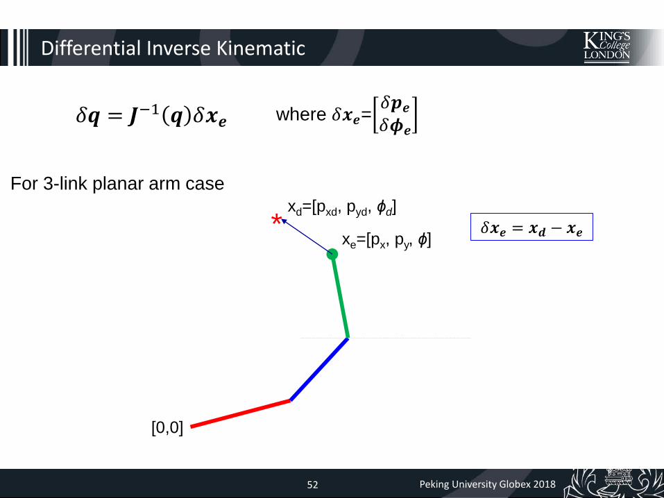
Differential Inverse Kinematic
𝛿𝒒 = 𝑱−1 𝒒 𝛿𝒙𝒆 where 𝛿𝒙𝒆=𝛿𝒑𝒆𝛿𝝓𝒆
For 3-link planar arm case
[0,0]
xe=[px, py, ɸ]
xd=[pxd, pyd, ɸd]
* 𝛿𝒙𝒆 = 𝒙𝒅 − 𝒙𝒆

Robotic Endovascular Interventions – Hamlyn Workshop 23 June 201553 Peking University Globex 201853
Differential Inverse Kinematic
For 3-link planar arm case
[0,0]
xe=[px, py, ɸ]
xd=[pxd, pyd, ɸd]
*
𝛿𝒙𝒆 = 𝒙𝒅 − 𝒙𝒆
𝛿𝜃1𝛿𝜃2𝛿𝜃3
=−𝑎1𝑠1 −𝑎2 𝑠12 −𝑎3 𝑠123 −𝑎2𝑠12 −𝑎3 𝑠123 −𝑎3𝑠123𝑎1𝑐1 +𝑎2 𝑐12 +𝑎3 𝑐123 𝑎2𝑐12 +𝑎3 𝑐123 𝑎3𝑐123
1 1 1
−1 𝛿𝑝𝑥𝛿𝑝𝑦𝛿𝜙
𝛿𝒒 = 𝑱−1 𝒒 𝛿𝒙𝒆

Robotic Endovascular Interventions – Hamlyn Workshop 23 June 201554 Peking University Globex 201854
𝛿𝒒 = 𝑱−1 𝒒 𝛿𝒙𝒆
Differential Inverse Kinematic
Inputs for differential inverse kinematic
changes of tool position and orientation
(𝛿𝑝𝑥 , 𝛿𝑝𝑦 , 𝛿𝜙)current actuator space (𝜃1, 𝜃2 𝜃3)

Robotic Endovascular Interventions – Hamlyn Workshop 23 June 201555 Peking University Globex 201855
𝛿𝒒 = 𝑱−1 𝒒 𝛿𝒙𝒆
Differential Inverse Kinematic
Output for differential inverse kinematic
current actuator space (𝜃1, 𝜃2 𝑎𝑛𝑑 𝜃3)
changes in actuator space (𝛿𝜃1, 𝛿𝜃2 𝛿𝜃3)
Therefore actuator space after the adjustment: 𝒒𝑎𝑑𝑗𝑢𝑠𝑡𝑒𝑑 = 𝛿𝒒 + 𝒒𝑐𝑢𝑟𝑟𝑒𝑛𝑡
changes of tool position and orientation
(𝛿𝑝𝑥 , 𝛿𝑝𝑦 , 𝛿𝜙)
Robotic Endovascular Interventions – Hamlyn Workshop 23 June 201556 Peking University Globex 201856
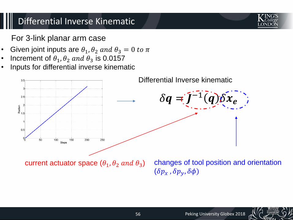
𝛿𝒒 = 𝑱−1 𝒒 𝛿𝒙𝒆
Differential Inverse Kinematic
• Given joint inputs are 𝜃1, 𝜃2 𝑎𝑛𝑑 𝜃3 = 0 𝑡𝑜 𝜋• Increment of 𝜃1, 𝜃2 𝑎𝑛𝑑 𝜃3 is 0.0157
• Inputs for differential inverse kinematic
Differential Inverse kinematic
current actuator space (𝜃1, 𝜃2 𝑎𝑛𝑑 𝜃3)
For 3-link planar arm case
changes of tool position and orientation
(𝛿𝑝𝑥 , 𝛿𝑝𝑦 , 𝛿𝜙)
Robotic Endovascular Interventions – Hamlyn Workshop 23 June 201557 Peking University Globex 201857
Programming exercise
Inverse_kinematic_fullrank_exercise_q.m
Differential Inverse Kinematic

Robotic Endovascular Interventions – Hamlyn Workshop 23 June 201558 Peking University Globex 201858
Differential vs. Analytical Inverse Kinematic
• From analytical inverse kinematics • Using differential inverse kinematic
Robotic Endovascular Interventions – Hamlyn Workshop 23 June 201559 Peking University Globex 201859
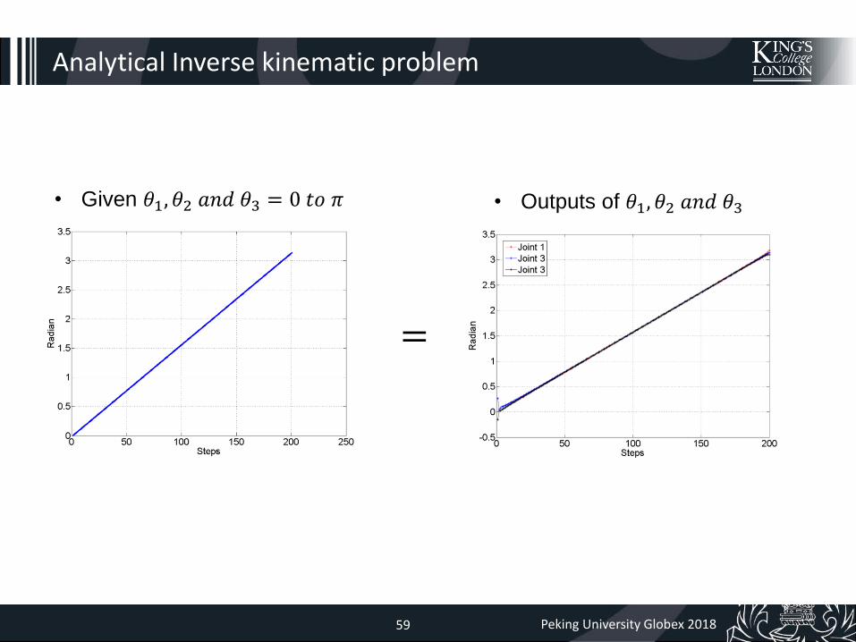
Analytical Inverse kinematic problem
• Given 𝜃1, 𝜃2 𝑎𝑛𝑑 𝜃3 = 0 𝑡𝑜 𝜋 • Outputs of 𝜃1, 𝜃2 𝑎𝑛𝑑 𝜃3
=

Robotic Endovascular Interventions – Hamlyn Workshop 23 June 201560 Peking University Globex 201860
Error of analytical inverse kinematic
Analytical Inverse Kinematics
Robotic Endovascular Interventions – Hamlyn Workshop 23 June 201561 Peking University Globex 201861
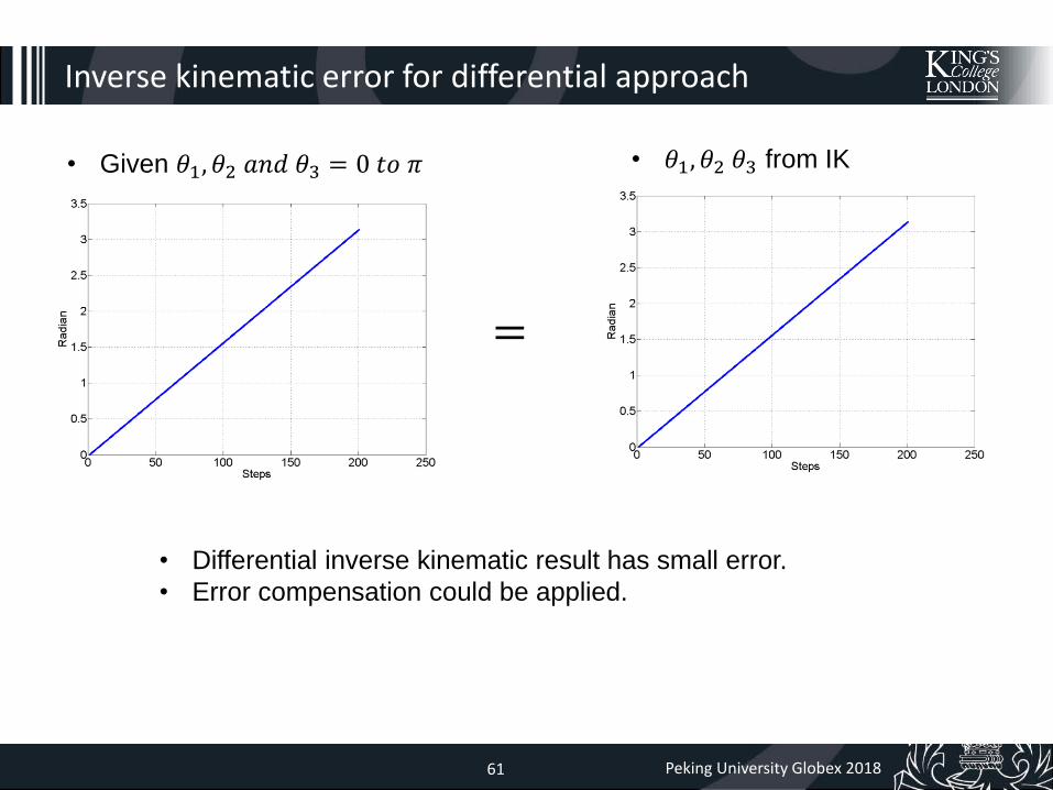
Inverse kinematic error for differential approach
• Given 𝜃1, 𝜃2 𝑎𝑛𝑑 𝜃3 = 0 𝑡𝑜 𝜋 • 𝜃1, 𝜃2 𝜃3 from IK
=
• Differential inverse kinematic result has small error.
• Error compensation could be applied.

Robotic Endovascular Interventions – Hamlyn Workshop 23 June 201562 Peking University Globex 201862
Inverse kinematic error for differential approach
Differential Inverse Kinematics


![MIF Report Amadou+Mariam BWO Paul Hamlyn[1]](https://static.fdocuments.in/doc/165x107/577d279b1a28ab4e1ea455dc/mif-report-amadoumariam-bwo-paul-hamlyn1.jpg)