Kinematics and Wear of Tool Blades for Scrap Tire...
18
MACHINING SCIENCE AND TECHNOLOGY Vol. 8, No. 2, pp. 193–210, 2004 Kinematics and Wear of Tool Blades for Scrap Tire Shredding Albert J. Shih 1, * and Ryan C. McCall 2 1 Department of Mechanical Engineering, University of Michigan, Ann Arbor, Michigan, USA 2 Department of Mechanical and Aerospace Engineering, North Carolina State University, Raleigh, North Carolina, USA ABSTRACT The wear of tool blades for cost-effective scrap tire shredding is investigated. Rotary disk cutters are widely used for cutting scrap tires into small pieces. The hard, wear-resistant tool blades mounted on the periphery of disk cutters maintain a narrow gap between blades and generate the cutting action. The kinematics of the relative motion of two adjacent disk cutters is derived to model the overlap region on blades during cutting. The model predictions match well with the actual shapes of the worn regions on used tool blades. The wear of tool blades made of AISI D2 and CRU-WEAR (CW) tool steels for scrap tire shredding is evaluated. A coordinate measurement machine was used to measure the tool wear. The wear on the blade surface is not uniform. Regions with high wear rate are explained using the kinematics analysis. The CW blades show a lower wear rate, about half of that of D2 blades, and a potential choice for cost savings. Key Words: Scrap tire processing; Kinematics; Tool wear. *Correspondence: Albert J. Shih, 1029 HH Dow, Department of Mechanical Engineering, University of Michigan, Ann Arbor, MI 48109, USA; Fax: 1-734-936-0363; E-mail: [email protected]. 193 DOI: 10.1081/MST-200028728 1091-0344 (Print); 1532-2483 (Online) Copyright & 2004 by Marcel Dekker, Inc. www.dekker.com
Transcript of Kinematics and Wear of Tool Blades for Scrap Tire...

MACHINING SCIENCE AND TECHNOLOGY
Vol. 8, No. 2, pp. 193–210, 2004
Kinematics and Wear of Tool
Blades for Scrap Tire Shredding
Albert J. Shih1,* and Ryan C. McCall
2
1Department of Mechanical Engineering, University of Michigan,
Ann Arbor, Michigan, USA2Department of Mechanical and Aerospace Engineering, North Carolina State
University, Raleigh, North Carolina, USA
ABSTRACT
The wear of tool blades for cost-effective scrap tire shredding is investigated.
Rotary disk cutters are widely used for cutting scrap tires into small pieces. The
hard, wear-resistant tool blades mounted on the periphery of disk cutters
maintain a narrow gap between blades and generate the cutting action. The
kinematics of the relative motion of two adjacent disk cutters is derived to model
the overlap region on blades during cutting. The model predictions match well
with the actual shapes of the worn regions on used tool blades. The wear of tool
blades made of AISI D2 and CRU-WEAR (CW) tool steels for scrap tire
shredding is evaluated. A coordinate measurement machine was used to measure
the tool wear. The wear on the blade surface is not uniform. Regions with high
wear rate are explained using the kinematics analysis. The CW blades show a
lower wear rate, about half of that of D2 blades, and a potential choice for cost
savings.
Key Words: Scrap tire processing; Kinematics; Tool wear.
*Correspondence: Albert J. Shih, 1029 HH Dow, Department of Mechanical Engineering,
University of Michigan, Ann Arbor, MI 48109, USA; Fax: 1-734-936-0363; E-mail:
193
DOI: 10.1081/MST-200028728 1091-0344 (Print); 1532-2483 (Online)
Copyright & 2004 by Marcel Dekker, Inc. www.dekker.com

ORDER REPRINTS
INTRODUCTION
Tires are nowadays designed and manufactured to be durable, wear-resistant,and stable in harsh environments. These performance advancements of tires typicallymake the processing of scrap tires more difficult. Annually, over 270 million scraptires are discarded in the United States. Scrap tires, if left unprocessed, can last forlong periods of time and become environmentally hazardous. There are three majorusages of scrap tires. One is the tire-derived fuel (ASTM D6700-01, 2001; Clark etal., 1993; Reisman, 1997; Snyder, 1998). Under a controlled environment, tires canbe cleanly burned as an energy source. Depending on the burner design, either thewhole tires or shredded tire pieces are used. The second usage of shredded scrap tirepieces is for landfill, septic drainage, and other civil engineering applications toreplace heavy and more expensive aggregates (ASTM D6270-98, 1998; Clark et al.,1993; Duff, 1995; Everett et al., 1996; Snyder, 1998). The third application of scraptires is to produce the crumb rubber, which can be used in rubber-modified asphaltfor more durable road pavements or molded to make cushion and vibration isolationparts (Clark et al., 1993; Snyder, 1998).
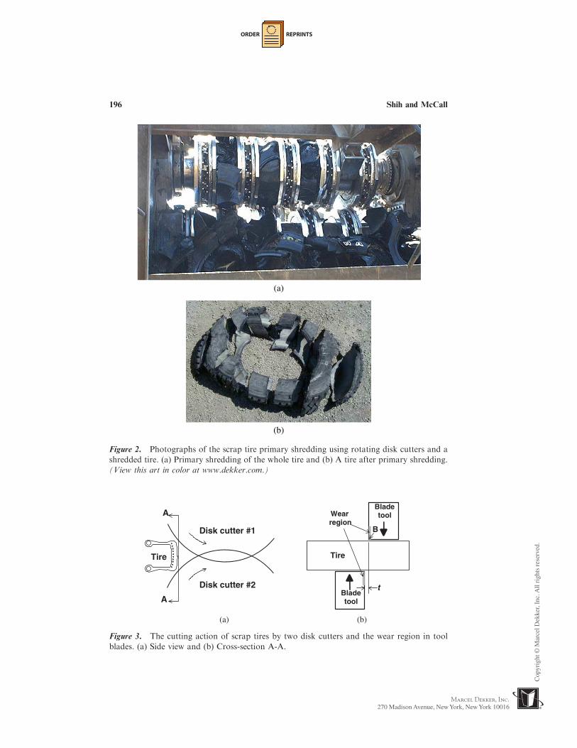
Most of the scrap tire applications require shredding to produce small tire pieceswith a uniform size. The most commonly used scrap tire shredding machines, asshown in Fig. 1, consist of arrays of rotating disk cutters driven by two parallelshafts rotating in opposite directions. Two operations, designated as the primary andsecondary shredding, are commonly used to cut scrap tires into small pieces.Figs. 1(a) and 1(b) show the arrangement and spacing of the disk cutters in theprimary and secondary tire shredding machines, respectively. The spacing betweenthe disks, w, as shown in Fig. 1(a), determines the average width of pieces cut. Thewhole tires are processed using the primary shredder with spacing between diskcutters, w, of about 150mm. Figure 2(a) shows a picture of a primary shreddercutting scrap tires. A tire cut by the primary shredder is shown in Fig. 2(b). Afterprimary shredding, the pieces of scrap tire are further processed by the secondaryshredder with an average spacing between disk cutters, as shown in Fig. 1(b), varyingfrom 40 to 50mm. The scrap tire pieces may go through the secondary shredderseveral times until the size meets the specification.
The concept of rotary disk cutting was first developed by Kurt Rosler in the1960s (Snyder, 1998). It has been used extensively for scrap tire shreddingapplications. As shown in Fig. 3, two rotating disks shear or cut the tire. Thenarrow gap between a set of two disk cutters, denoted as t in Fig. 1, generates thecutting action. Figure 3(a) shows the side view of two disk cutters and the cross-section of a tire with steel wires and beads. The cross-section A-A is shown inFig. 3(b), which illustrates two tool blades and the gap, t. Figure 3(b) also indicatesthe tool blade wear regions, which occur close to the gap between tool blades on theperiphery of disk cutters.
The three-body wear due to sand and other hard debris carried by scrap tires hasbeen identified as the major blade wear mechanism (Snyder, 1998). The blade wearincreases the gap width, t, and gradually deteriorates the shearing or cutting action.As the gap reaches a threshold level, the steel wire in the tire starts to pull out and therubber is drawn between blades in the cut region. This creates the high friction forcebetween adjacent blades and increases the power required for shredding. Eventually,
194 Shih and McCall

ORDER REPRINTS
the side surfaces on worn blades need to be reground to remove the wear region andrestore the blade sharpness for reuse.
Cost is an important criterion in the development of feasible and sustainablescrap tire processing technologies. Tooling and labor costs are two major expenses inshredding scrap tires (Snyder, 1998). Each disk, as shown in Fig. 4(a), consists of 12removable blades made of wear-resistant tool steels. The primary shredding machineshown in Fig. 1(a) has 240 blades on 20 cutting disks. The secondary shreddingmachine shown in Fig. 1(b) has 288 blades on 24 cutting disks. These numbersillustrate the significance of tooling cost for shredding scrap tires. Tool wearreduction is important to reduce the cost for scrap tire shredding. The labor cost to
t
Shaft 1
Shaft 2
w
(a)
t
50.8 48.850.848.8 46.746.7 44.7 42.7 40.644.742.740.6
40.6 50.848.846.744.742.7 50.8 48.8 46.7 44.7 42.7 40.6
Shaft 1
Shaft 2
(b)
Figure 1. Configuration of rotary disk cutters used for primary and secondary shredding of
scrap tires. (a) Primary shredding and (b) Secondary shredding (unit: mm).
Kinematics and Wear of Tool Blades for Scrap Tire Shredding 195
ORDER REPRINTS
(a)
(b)
Figure 2. Photographs of the scrap tire primary shredding using rotating disk cutters and a
shredded tire. (a) Primary shredding of the whole tire and (b) A tire after primary shredding.
(View this art in color at www.dekker.com.)
A
A
Tire
Disk cutter #1
Disk cutter #2
Tire
t
Bladetool
Bladetool
Wearregion
B
(a) (b)
Figure 3. The cutting action of scrap tires by two disk cutters and the wear region in tool
blades. (a) Side view and (b) Cross-section A-A.
196 Shih and McCall
ORDER REPRINTS
replace and realign all worn blades on the disk cutters with a precise, narrow gap isalso noteworthy in the total operation cost.
Better, more wear-resistant tool steels can be used to increase the blade life andreduce the machine down time and labor cost. Blades made of more expensive andwear-resistant tool steels can increase the tool life to a level that the overall operationcost for scrap tire shredding is reduced. Three goals of this research are to: (1) selectand test a more wear-resistant material for the tool blade, (2) study the wear patternand kinematics of disk cutting, and (3) measure the blade wear and compare theperformance of two different tool steels.
(a)
12.738.1
63.588.9
114.3139.7
152.4
28.133.1
139.0
38.1
60°
a b c d e f gIII
(b)
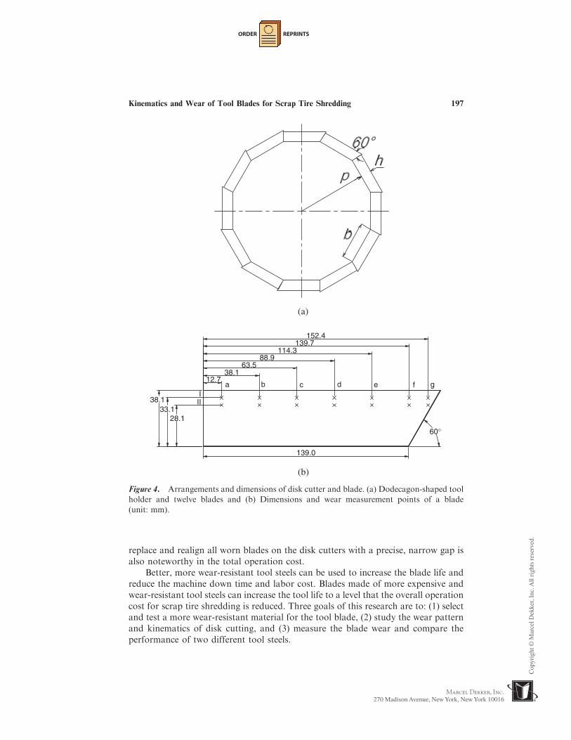
Figure 4. Arrangements and dimensions of disk cutter and blade. (a) Dodecagon-shaped tool
holder and twelve blades and (b) Dimensions and wear measurement points of a blade
(unit: mm).
Kinematics and Wear of Tool Blades for Scrap Tire Shredding 197

ORDER REPRINTS
In this article, the evaluation and selection of a new tool blade material are firstintroduced. The kinematics of the disk cutting is then derived. Modeling results arecompared to experimental observations. Tool wear measurement using a coordinatemeasurement machine (CMM) is described. Results and discussions of tool wear arethen presented.
TOOL MATERIAL SELECTION
In the past decade, two popular blade materials used for scrap tire shreddinghave been the AISI 4340 and D2 tool steels. AISI 4340, heated-treated to about 40Rc, was the blade material used in early scrap tire shredding machines. The AISI D2tool steel, denoted as D2 hereafter, can be air hardened to about 60Rc and is morewear-resistant than AISI 4340. D2, although more expensive than AISI 4340, is oneof the lowest cost tool steels and has become a popular choice of blade material forscrap tire shredding applications. The typical composition of D2 is 12% Cr, 1% Mo,1% V, 1.5 % C, Fe accounting for the balance. D2 is a widely used tool steel and hasbeen studied extensively. For example, Ma et al. (2000) investigated the abrasivewear of hardened D2 tool steel and Poggie and Wert (1991) studied the effect ofsurface finish and residual stress on the wear of D2 tool.
The design of blades with inserts made of tungsten carbide in cobalt matrix(WC-Co) was considered but was not adopted due to the following reasons. First,the blade is subject to impact forces from foreign objects hiding in scrap tires. Mostof the D2 blades used in scrap tire shredding have impact chipping damages. Thebrittle WC-Co inserts are more likely to chip and break rapidly under the impactforce. Second, a tool steel blade with WC-Co inserts needs a different grindingtechnology, most likely CBN grinding, to restore sharpness for reuse which wouldincrease tooling and operating costs. Third, the design of a secure, easy to removeand install, and cost-effective way to fixture WC-Co inserts on the tool blade is nottrivial. With these considerations, the WC-Co insert in tool blade was not used inthis study. Therefore, this research is focused on the selection of another type of toolsteel that is more wear-resistant than D2 and still cost-effective.
A wide variety of tool steels and heat treatment procedures are available forselection Roberts et al. (1998). In this study, three alternative tool materials, CRU-WEAR (denoted as CW hereafter), CPM 3V, and M-42, were evaluated. During theselection process, users of the scrap tire shredding machines imposed very strictconstraints on cost. The cost of heat-treated blades made of CPM 3V and M-seriestool steels are, in general, two to four times more expensive than D2. The lowtoughness of the hard, wear-resistant M-series tool steel is also a concern. CW toolsteel contains about 7.50% Co, 2.40% V, 1.60% Mo, 1.15% W, 1.10% C, 1.10%Si, 0.35% Mg, balanced by Fe. It can be air hardened and has a good combinationof hardness, wear-resistance, toughness, and cost (Tarney, 1997; Tool Steel andSpecialty Alloy Selector, 2002). The basis for improved wear resistance in CW toolsteel is the substitution of higher hardness vanadium carbide (28 to 30GPa Vickershardness) for the chromium carbide (18 to 22GPa Vickers hardness) in D2.
198 Shih and McCall

ORDER REPRINTS
A hardness measurement in the Rockwell C scale was conducted on worn CWand D2 blades to compare their mechanical properties. The hardness indentswere made in both worn and unworn regions of tool blades. An average hardness of61.0 and 58.3Rc in the worn region and 59.3 and 56.0Rc in the unworn region wasrecorded for the heat-treated CW and D2 blades, respectively. This indicates thatthe CW blade is a harder and potentially more wear-resistant tool steel than theD2 blade.
In this study, twelve CW blades were mixed with 276 D2 blades in a secondaryshredding machine (Fig. 1(b)) to compare the performance of these two toolmaterials. After shredding scrap tires for 15 days with an average operating time of10 h per day, the worn blades were removed and examined. The next sectiondiscusses the kinematics of relative motion of a set of two disk cutters to analyze theworn region on tool blades.
KINEMATICS OF TOOL BLADE CUTTING
The arrangements and dimensions of the twelve tool blades on the dodecagon-shaped tool holder for the disk cutter used in this study are shown in Fig. 4(a). Theshortest distance from the side of the polygon tool holder to its center is designatedas p. The height of the blade is h. Each blade has a 60� angle tip to allow the stackingof blades around the dodecagon-shaped tool holder. Figure 4(b) shows the geometryand dimensions of the tool blade and the location of two rows and seven columns ofwear measurement points used in this study. The base for the blade b is equal to2p tan15�. In this study, the actual disk tool geometry of p¼ 259.5mm, h¼ 38.1mm,and b¼ 139.0mm were used.
Two adjacent counter rotating disks are used as a set to shred scrap tires.Figure 5 shows the front view of the arrangement of two disks, marked as Disk 1 andDisk 2 with centers at O1 and O2, respectively. The distance between O1 and O2 is d.Two disks rotate at the same angular speed, !, in opposite directions. An offsetangle, �, is used to specify the relative orientation of these two disks. As shown inFig. 5(a), the angle � is zero when the outside edges of the blades in two adjacentrotating disks are parallel to each other and perpendicular to line O1O2 at aninstantaneous time in the overlap area. The offset angle �, as shown in Fig. 5(b), isdefined as the angle that Disk 2 rotates in advance from the �¼ 0 position inFig. 5(a). The range of � is from 0� to 30� for the disk with twelve tool blades(Fig. 4(a)) used in this study. The change in offset angle will alter the wear pattern onthe blade surface, as will be demonstrated in the following analysis.
Figure 6 shows the kinematics of the relative motion of a point P on Disk 2relative to a blade in Disk 1. The relative position of two disks at time t is shown inFig. 6(a). Two coordinate systems are first defined. An x-y coordinate system iscentered at O1 and fixed on Disk 1. Another u-v coordinate system is centered at O2
and fixed on Disk 2. The x- and u-axes are both in the direction from O1 to O2
at time t. The position of P in the x-y coordinate at time t is represented by:
fO1Pgt ¼ fO1O2gt þ fO2Pgt ð1Þ
Kinematics and Wear of Tool Blades for Scrap Tire Shredding 199

ORDER REPRINTS
where {O1P}t is the vector from point O1 to P at time t, {O1O2}t is the vector frompoint O1 to O2 at time t, and {O2P}t is the vector from point O2 to P at time t. Allvectors are referenced to the x–y coordinate system.
At time tþ�t, both disks have rotated by an angle �¼!�t and the orientation ofcoordinate systems x-y and u-v has changed. As shown in Fig. 6(b), the x-y coordinatefixed on Disk 1 is rotated in the c.w. direction by an angle �. The u-v coordinate fixedon Disk 2 is rotated in the c.c.w. direction by an angle �. The angle between theu- and x-axes is 2�. The point P on Disk 2 is rotated in the c.c.w. direction to thenew position P0. The position of P0 in the x-y coordinate at time tþ�t is
fO1P0gtþ�t ¼ fO1O2gtþ�t þ fO2P
0gtþ�t ð2Þ
(a)
(b)
Disk 1 Disk 2
Figure 5. Definition of the offset angle �. (a) Two disks with offset angle �¼ 0 and (b) Two
disks offset by an angle �.
200 Shih and McCall

ORDER REPRINTS
where {O1P0}tþ�t is the vector from point O1 to P0 at time tþ�t, {O1O2}tþ�t is
the vector from point O1 to O2 at time tþ�t, and {O2P0}tþ�t is the vector from
point O2 to P0 at time tþ�t. The vector {O1O2}tþ�t and {O2P0}tþ�t can be derived
from {O1O2}t and {O2P}t using the rotational transformation matrix.
fO1O2gtþ�t ¼ ½T��fO1O2gt ð3ÞfO2P
0gtþ�t ¼ ½T2��fO2Pgt ð4Þwhere
½T�� ¼cos � � sin �
sin � cos �
� �
½T2�� ¼cos 2� � sin 2�
sin 2� cos 2�
� �
y
x
P v
u1 2
(a)
x
yP
vuP'
1 2
(b)
Figure 6. Analysis of the relative motion of two disk tools. (a) Time t and (b) Time tþ�t
(�¼!�t).
Kinematics and Wear of Tool Blades for Scrap Tire Shredding 201
ORDER REPRINTS
Due to the rotation of both disks, the vector {O2P0}tþ�t is rotated from {O2P}t
by an angle 2�. This can be explained by the 2� rotation of the u-v coordinate relativeto the x-y coordinate, as shown in Fig. 6(b). Equation (2) is applied to calculate newpositions of the points on the periphery of Disk 2 relative to a blade on Disk 1.Assuming the sizes of the two disks are identical, the four parameters required as theinput for the analysis are: p, b, d, and �.
WEAR PATTERN MODELING RESULTS AND COMPARISON
WITH EXPERIMENTAL OBSERVATION
Figure 7 shows photographs of two worn CW blades after cutting scrap tires.The modeling results of two blades on Disk 2 relative to a blade on Disk 1 at 11different positions are also shown in Fig. 7. On one side of the blade surface, a wornregion can be identified. Two distinctly different shapes of worn regions are observedin photographs of worn blades in Figs. 7(a) and 7(b). In the worn region, a pocketthat penetrates deep into the blade can be seen. The wear pocket on each blade ismarked in Fig. 7. Since the three parameters p (¼259.5mm), b (¼38.1mm), andd (¼588.0mm) remain the same in the scrap tire cutting test, the change in disk offsetangle � is the likely cause for the different shapes of worn regions and locations ofthe pocket.
The distance between disk centers, d, and the offset angle, �, are difficult tomeasure accurately in the machine setup. These two parameters were adjusted inthe modeling to match the blade overlap region to the shape of the worn regionsshown in photographs of worn blades. As shown in Figs. 7(a) and 7(b), the shapeof the overlap regions for d¼ 588mm and �¼ 22.5� and 7.5� exhibit goodmatch. In Fig. 7, two blades on Disk 2 at 11 positions are marked by differentline styles. Positions 1 and 11 are close to the location where the two blades onDisk 1 start and end the contact with the blade on Disk 1, respectively. Theincrease in each position number represents the rotation of an angle � of 1.35� byeach disk.
The overlap regions in analysis show some discrepancies to the actual shapeof the worn regions in used blades. Several possible causes for such discrepanciesare identified. First, the edge of the blade, as marked by B in Fig. 3(b), cannotmaintain a perfect 90� sharpness. It is worn and rounded to a radius and will changethe shape of the wear region. Second, the two shafts carrying heavy disk cutterswill deflect slightly by the weight and cutting forces. These disks also cannot aligneach other perfectly as shown in Fig. 1. The deflection and misalignment createan angle of approach and departure between two disk cutters and vary the shape ofthe worn region. Third, all blades are assumed fixed on a perfect dodecagon-shapedtool holder. The orientation of these blades and gap between each blade can changethe geometry of the ideal disk shown in Fig. 4(a) and alter the shape of the wornregion.
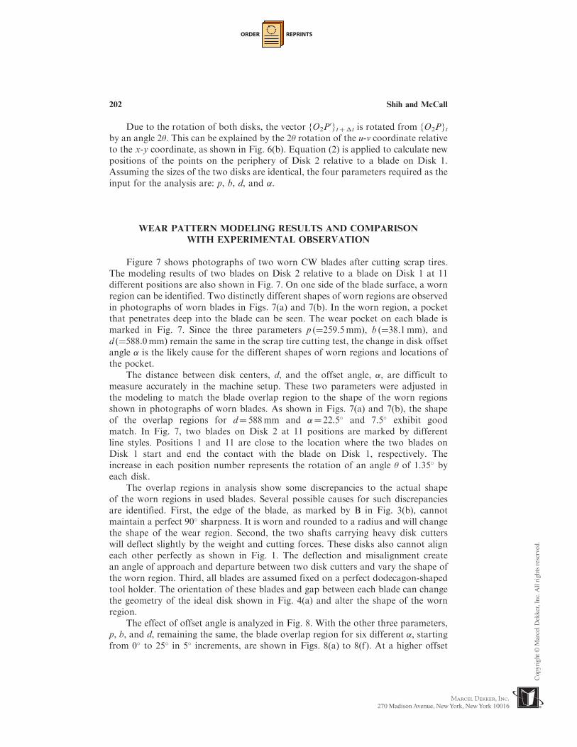
The effect of offset angle is analyzed in Fig. 8. With the other three parameters,p, b, and d, remaining the same, the blade overlap region for six different �, startingfrom 0� to 25� in 5� increments, are shown in Figs. 8(a) to 8(f). At a higher offset
202 Shih and McCall

ORDER REPRINTS
Bladeon
Disk 1
1
2
3
4
56
78910
11
Bladeon
Disk 1
1 2 3 4 5
6
7
8
9
10
11
(a)
(b)
Pocketin worn region
Pocketin worn region
Chipping
Chipping
Figure 7. Photographs of the worn blades and comparison with the analysis results
( p¼ 259.5mm, b¼ 38.1mm, and d¼ 588.0mm). (a) �¼ 22.5� and (b) �¼ 7.5�. (View image in
color online.)
Kinematics and Wear of Tool Blades for Scrap Tire Shredding 203
ORDER REPRINTS
angle, the pocket that penetrates into the blade gradually moves down from the topof the blade. This further confirms that the different worn regions observed inFigs. 7(a) and 7(b) are caused by the change in offset angle. Besides the offset angle,the center distance d can also affect the overlap area. The change in d creates
Figure 8. The effect of offset angle on the wear region ( p¼ 259.5mm, b¼ 38.1mm, and
d¼ 588.0mm). (a) �¼ 0�, (b) �¼ 5�, (c) �¼ 10�, (d) �¼ 15�, (e) �¼ 20�, and (f) �¼ 25�. (Viewimage in color online.)
204 Shih and McCall
ORDER REPRINTS
a translational movement of the blade in Disk 1 in the horizontal direction from theposition shown in Fig. 8.
TOOL WEAR MEASUREMENT RESULTS AND DISCUSSIONS
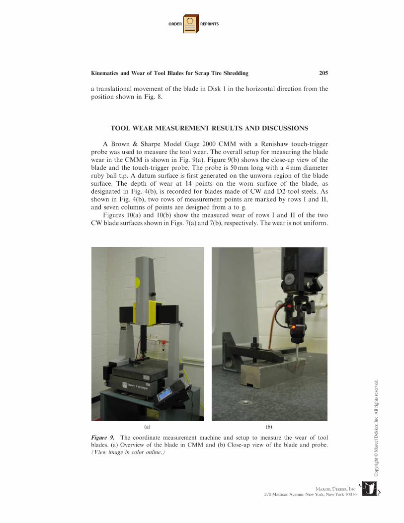
A Brown & Sharpe Model Gage 2000 CMM with a Renishaw touch-triggerprobe was used to measure the tool wear. The overall setup for measuring the bladewear in the CMM is shown in Fig. 9(a). Figure 9(b) shows the close-up view of theblade and the touch-trigger probe. The probe is 50mm long with a 4mm diameterruby ball tip. A datum surface is first generated on the unworn region of the bladesurface. The depth of wear at 14 points on the worn surface of the blade, asdesignated in Fig. 4(b), is recorded for blades made of CW and D2 tool steels. Asshown in Fig. 4(b), two rows of measurement points are marked by rows I and II,and seven columns of points are designed from a to g.
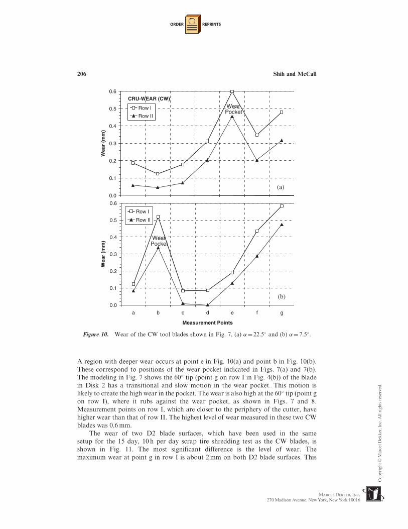
Figures 10(a) and 10(b) show the measured wear of rows I and II of the twoCW blade surfaces shown in Figs. 7(a) and 7(b), respectively. The wear is not uniform.
(a) (b)
Figure 9. The coordinate measurement machine and setup to measure the wear of tool
blades. (a) Overview of the blade in CMM and (b) Close-up view of the blade and probe.
(View image in color online.)
Kinematics and Wear of Tool Blades for Scrap Tire Shredding 205
ORDER REPRINTS
A region with deeper wear occurs at point e in Fig. 10(a) and point b in Fig. 10(b).These correspond to positions of the wear pocket indicated in Figs. 7(a) and 7(b).The modeling in Fig. 7 shows the 60� tip (point g on row I in Fig. 4(b)) of the bladein Disk 2 has a transitional and slow motion in the wear pocket. This motion islikely to create the high wear in the pocket. The wear is also high at the 60� tip (point gon row I), where it rubs against the wear pocket, as shown in Figs. 7 and 8.Measurement points on row I, which are closer to the periphery of the cutter, havehigher wear than that of row II. The highest level of wear measured in these two CWblades was 0.6mm.
The wear of two D2 blade surfaces, which have been used in the samesetup for the 15 day, 10 h per day scrap tire shredding test as the CW blades, isshown in Fig. 11. The most significant difference is the level of wear. Themaximum wear at point g in row I is about 2mm on both D2 blade surfaces. This
0.0
0.1
0.2
0.3
0.4
0.5
0.6
a b c d e f g
Measurement Points
Wea
r (m
m)
Row I
Row II
WearPocket
(a)
(b)
CRU-WEAR (CW)
0.0
0.1
0.2
0.3
0.4
0.5
0.6
Wea
r (m
m)
Row I
Row II
WearPocket
Figure 10. Wear of the CW tool blades shown in Fig. 7, (a) �¼ 22.5� and (b) �¼ 7.5�.
206 Shih and McCall

ORDER REPRINTS
illustrates the wear-resistance advantage of the CW steel for scrap tire shredding.Similar to the trend observed in Fig. 10, measurement points on row I also havehigher wear than that of row II. The wear in the pocket of the worn region forthe D2 blade, as shown at point b in Fig. 11(b), is not as obvious as in theCW blade.
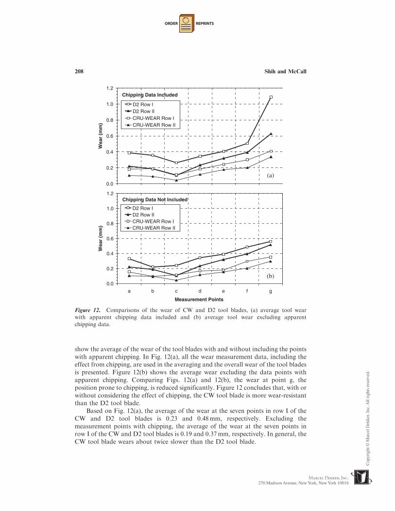
To further quantify the wear of two tool steels used in this study, a total oftwelve CW blades and eight D2 tool blades used in the test were measured usingthe CMM. The measured wear data of these blades were averaged and compared.Figure 12 shows the average wear of measurement points on rows I and II of theCW and D2 blades.
Chipping of the tool blade was observed on both CW and D2 blades used in thisstudy. Examples of chipping on the blade are indicated in Figs. 7(a) and 7(b). Themeasurement points with chipping can be visually identified. Two graphs in Figs. 12
0.0
0.5
1.0
1.5
2.0
2.5
a b c d e f g
Measurement Points
Wea
r (m
m)
Row I
Row II
(a)
(b)
AISI D2
0.0
0.5
1.0
1.5
2.0
2.5
Wea
r (m
m)
Row IRow II
Figure 11. Wear of AISI D2 tool blades, (a) �¼ 22.5� and (b) �¼ 7.5�.
Kinematics and Wear of Tool Blades for Scrap Tire Shredding 207
ORDER REPRINTS
show the average of the wear of the tool blades with and without including the pointswith apparent chipping. In Fig. 12(a), all the wear measurement data, including theeffect from chipping, are used in the averaging and the overall wear of the tool bladesis presented. Figure 12(b) shows the average wear excluding the data points withapparent chipping. Comparing Figs. 12(a) and 12(b), the wear at point g, theposition prone to chipping, is reduced significantly. Figure 12 concludes that, with orwithout considering the effect of chipping, the CW tool blade is more wear-resistantthan the D2 tool blade.
Based on Fig. 12(a), the average of the wear at the seven points in row I of theCW and D2 tool blades is 0.23 and 0.48mm, respectively. Excluding themeasurement points with chipping, the average of the wear at the seven points inrow I of the CW and D2 tool blades is 0.19 and 0.37mm, respectively. In general, theCW tool blade wears about twice slower than the D2 tool blade.
Chipping Data Not Included
0.0
0.2
0.4
0.6
0.8
1.0
1.2
a b c d e f g
Measurement Points
Wea
r (m
m)
D2 Row ID2 Row IICRU-WEAR Row ICRU-WEAR Row II
(b)
(a)
Chipping Data Included
0.0
0.2
0.4
0.6
0.8
1.0
1.2
Wea
r (m
m)
D2 Row ID2 Row IICRU-WEAR Row ICRU-WEAR Row II
Figure 12. Comparisons of the wear of CW and D2 tool blades, (a) average tool wear
with apparent chipping data included and (b) average tool wear excluding apparent
chipping data.
208 Shih and McCall

ORDER REPRINTS
The cost of CW tool blade is more expensive, but usually not twice moreexpensive than the D2. Further operational cost savings can be achieved byextending the tool changeover period and reduce the machine down time and laborcost for replacing, regrinding, and installing the tool blades.
CONCLUDING REMARKS
The wear of tool blades made of D2 and CW tool steels were evaluated forscrap tire shedding. The CW tool steel showed about half the wear rate comparedto the D2. The application of tool blades made of CW tool steel potentially has anoverall cost advantage. The kinematics of blades on a set of two cutter disks wasderived to model the relative motion of the tool blades. The modeling of the overlapregion between blades matched well with experimental observations of the wearregions on the tool blades. The analysis also showed the slow motion of the 60� tip ofthe tool blade around a pocket in the worn region and explained the high wear in thepocket and at the tool tip.
This research on scrap tire shredding has generated two topics worthy of furtherinvestigation. One is to understand the abrasive wear mechanism between toolblades. The kinematics modeling presented in this study is not enough to understandthe blade wear. The other is the finite-element modeling of the shear cutting action tostudy the effect of the blade gap, t, on the scrap tire shredding.
ACKNOWLEDGMENTS
The authors acknowledge supports from the Solid Waste Division of NorthCarolina Department of Environment and Natural Resource, particularly theproject management of Pam Moore and Paul Crissman, and the National ScienceFoundation (Grant #0099829). Technical assistances form Mark Diemunsch ofBarclay Roto-Shred Inc., Robert Hinger of US Tire Recycling, and Edward Tarneyof Crucible Materials Corp. are also gratefully acknowledged.
REFERENCES
ASTM D6270-98. (1998). Standard Practice for the Use of Scrap Tires in CivilEngineering Applications. West Conshohocken, Pennsylvania: AmericanSociety for Testing and Materials.
ASTM D6700-01. (2001). Standard Practice for Use of Scrap Tire-Derived Fuel.West Conshohocken, Pennsylvania: American Society for Testing andMaterials.
Clark, C., Meardon, K., Russell, D. (1993). Scrap Tire Technology and Markets.Park Ridge, New Jersy: Noyes Publications.
Duff, D. P. (1995). Using tire chips as a drainage layer. Waste Age 26(9):6.
Kinematics and Wear of Tool Blades for Scrap Tire Shredding 209

ORDER REPRINTS
Everett, J. W., Gattis, J. L., Wallace, B. (1996). Drainage pipe from scrap truck tires.Journal of Solid Waste Technology and Management 23(1):34–43.
Ma, X., Liu, R., Li, D. Y. (2000). Abrasive wear behavior of D2 tool steel withrespect to load and sliding speed under dry sand/rubber wheel abrasioncondition. Wear 241:79–85.
Poggie, R. A., Wert, J. J. (1991). Influence of surface finish and strain hardening onnear-surface residual stress and the friction and wear behavior of A2, D2 andCPM-10V tool steels. Wear 149:209–220.
Reisman, J. I. (1997). Air Emissions from Scrap Tire Combustion, US EnvironmentalProtection Agency Report EPA-600/R-97-115.
Roberts, G. A., Krauss, G., Kennedy, R. (1998). Tool Steels. 5th ed. Materials Park,Ohio: ASM International.
Snyder, R. (1998). Scrap Tires: Disposal and Reuse. Warrendale, Pennsylvania:Society of Automotive Engineer.
Tarney, E. (1997). Selecting high performance tool steels for metal forming tools.Metal Forming 31(9):35–41.
Tool Steel and Specialty Alloy Selector. (2002). Camillus, New York: CrucibleService.
210 Shih and McCall