KII Series / World K Series / BH Series Single-Phase Induction Motors
34
C-113 Standard AC Motors C-113 Constant Speed Motors Overview, Product Series Three-Phase Induction Motors Single-Phase Induction Motors Reversible Motors Electromagnetic Brake Motors Clutch & Brake Motors Low-Speed Synchronous Motors Torque Motors Watertight, Dust-Resistant Motors Right-Angle Gearheads Linear Heads Brake Pack Accessories Installation Single-Phase Induction Motors Page Features and Types of Single-Phase Induction Motors··· C-114 General Specifications ········································· C-119 K Series [6 W∼90 W (1/125 HP∼1/8 HP)] ········· C-120 BH Series [200 W (1/4 HP)] ·································· C-134 2-Pole, High-Speed Type [40 W∼150 W (1/19 HP∼1/5 HP)] ··· C-142 Standard AC Motors Constant Speed Motors Single-Phase Induction Motors
-
Upload
nguyencong -
Category
Documents
-
view
219 -
download
0
Transcript of KII Series / World K Series / BH Series Single-Phase Induction Motors

C-113
Standard AC Motors C-113
Constant
Speed
Motors
Overview,
Product
Series
Three-Phase Induction Motors
Single-PhaseInduction Motors
Reversible Motors
Electromagnetic Brake Motors
Clutch & Brake Motors
Low-Speed Synchronous Motors
Torque
Motors
Watertight,
Dust-Resistant
Motors
Right-Angle
Gearheads
Linear
Heads
Brake Pack
Accessories
Installation
Single-Phase
Induction Motors
Page
Features and Types of Single-Phase Induction Motors··· C-114General Specifications ········································· C-119K Series [6 W∼90 W (1/125 HP∼1/8 HP)] ········· C-120BH Series [200 W (1/4 HP)] ·································· C-1342-Pole, High-Speed Type [40 W∼150 W (1/19 HP∼1/5 HP)] ··· C-142
Standard AC Motors
Constant Speed Motors
Single-Phase Induction Motors

C-114
C-114 Single-Phase Induction Motors
ORIENTAL MOTOR GENERAL CATALOG 2015/2016
6 W
(1/125 HP)
15 W
(1/50 HP)
25 W
(1/30 HP)
40 W
(1/19 HP)
60 W
(1/12 HP)
90 W
(1/8 HP)
BH Series
200 W
(1/4 HP)
2-Pole High-Speed
40-150 W (1/19-1/5 HP)
Features and Types of Single-Phase Induction Motors
■ Features of Single-Phase Induction
Motors
●Optimal for Uni-Directional and Continuous OperationInduction motors are optimal for uni-directional and continuous operation such as a conveyor system.
●Easy OperationAll you need is to connect a capacitor and plug the motor into an AC power supply and the motor can be easily operated.
●Extensive Product LineThe K Series, World K Series and BH Series are available.We have products with an output power range of 6 W (1/125 HP) to 200 W (1/4 HP), so you can find a motor that meets your specific application.
●Compatible with Various GearheadsCombination with a gearhead allows the motor speed to be reduced to the required speed or generate higher torque.
■Types of Single-Phase Induction Motors
Series Features, Product Line
K Series ●New Global StandardWith a high performance gearhead built in, it is the new global standard for standard AC motors.Features of the K Series ➜ Page C-115
●Conforms to Standards
●Product LineFrame Size □60 mm (□2.36 in.)∼□90 mm (□3.54 in.)
Output PowerTerminal Box Type: 25 W∼90 W (1/30 HP∼1/8 HP)Lead Wire Type: 6 W∼90 W (1/125 HP∼1/8 HP)
TypeTerminal Box Type: Parallel shaftLead Wire Type: Parallel shaft
VoltageSingle-Phase 110/115 VAC,Single-Phase 220/230 VAC
World K Series2-Pole, High-Speed Type
●Conforms to StandardsAll World K Series products have an overheat protection device built-in and conform to major safety standards.
● Applicable StandardsUL/CSA StandardsCertified under the China Compulsory Certification System (CCC System)CE Marking (Low Voltage Directive)
● Motor Overheat Protection DeviceThermal Protector
●Product LineFrame Size □80 mm (□3.15 in.), □90 mm (□3.54 in.)
Output Power 2-Pole, High-Speed Type: 40 W∼150 W (1/19 HP∼1/5 HP)
VoltageSingle-Phase 110/115 VACSingle-Phase 220/230 VAC
BH Series ●Smallest Frame Size among 200 W (1/4 HP) Motors
These motors achieve a high output of 200 W (1/4 HP) with a frame size of 104 mm (4.09 in.).
●Hypoid Gear Right Angle Type is Available.
●"Combination Type" for Easy InstallationWith each combination type, the motor and gearhead come pre-assembled for easy installation into your equipment.
●Conforms to Standards and Global Voltage Specifications
●Tapped Hole at the Shaft EndThe gearhead shaft features a tapped hole for convenient connection with loads.
●Product LineFrame Size □104 mm (□4.09 in.)
Output Power 200 W (1/4 HP)
Type
Terminal Box Type: Right-Angle, Hollow Shaft Type, Right-Angle, Solid Shaft Type, Parallel Shaft Type, Round Shaft TypeCable Type: Right-Angle, Hollow Shaft Type, Right-Angle, Solid Shaft Type, Parallel Shaft Type, Round Shaft Type
VoltageSingle-Phase 110/115 VACSingle-Phase 220/230 VAC

C-115
Standard AC Motors C-115
Constant
Speed
Motors
Overview,
Product
Series
Three-Phase Induction Motors
Single-PhaseInduction Motors
Reversible Motors
Electromagnetic Brake Motors
Clutch & Brake Motors
Low-Speed Synchronous Motors
Torque
Motors
Watertight,
Dust-Resistant
Motors
Right-Angle
Gearheads
Linear
Heads
Brake Pack
Accessories
Installation
CAD DataManuals
www.orientalmotor.com Technical Support
TEL: (800) 468-3982E-mail: [email protected]
■K Series Features
Excellent Motor PerformanceThe magnetic balance for each input voltage has been re-examined and the motors have been specially designed to optimize their characteristics.Designing specifically for each voltage not only improves efficiency, but also contributes to equipment reliability by reducing heat and vibration generated by the motor.
Comparison with conventional product
Heat Generated Vibration Efficiency
Max. 20°C (68°F)Decrease
Max. 35%Decrease
Max. 9%Increase
●Energy Savings
Pow
er C
onsu
mpt
ion
[W]
Output Power
Loss
Power consumptionreduced by 28 W
0
50
100
150
58
90
86
90
Conventional Product90 W (1/8 HP)
KⅡ Series90 W (1/8 HP)
[For 90 W (1/8 HP) Output Power Single-phase 200 VAC 60 Hz]
Built-In Slim Body Terminal Box (Terminal box type)A new shape of terminal box was designed to make wiring the terminal block easier. It is slimmer than conventional products, and the cable outlet can be rotated in 90˚ increments for 4 possible directions.
Conventional Product KⅡ Series
●IP66 Compliant Drip-proof SpecificationThe seal structure for the motor, gearhead and terminal box components has been strengthened. The terminal box type is compliant with the IP66 degree of protection.IP66: The IP indication that shows the watertight and dust-resistant performance are specified under IEC 60529 and IEC 60034-5.
Main Specifications ●Material
Case and terminal box: AluminumOutput shaft: S45CScrews: Stainless steel (externally facing screws only)
●Surface TreatmentCase and terminal box: Painted (excluding installation surface)
Equipped with a High-Performance Gearhead
●High Permissible TorqueThe permissible torque is up to twice that of conventional products.
Max. Permissible Torque
16 N·m (141 lb-in.)
KⅡ Series 4GV
Max. Permissible Torque
8 N·m (70 lb-in.)
Oriental MotorConventional Product 4GN-K
● 25 W (1/30 HP) Gearhead Output Torque (Permissible)
50 100 150 200 250 300 3500
4
8
12
16
Gear Ratio
Perm
issi
ble
Torq
ue [N
·m]
Permissible Torque Doubled
High Gear RatioOriental Motor's Conventional Geared Motor
KⅡ Series
Perm
issi
ble
Torq
ue [l
b-in
]
160
120
80
40
0
◇Downsizing is Possible with the Same Output TorqueDownsizing is possible by changing our company's conventional products with the K Series. If a smaller size motor can be selected, not only the power consumption but also the purchase cost can be reduced.
□80 (3.15)□90 (3.54)
Oriental Motor's Conventional Motor KⅡ Series
Energy-SavingReduced Costs
List Price $209.00 List Price $153.00
Frame Size: □90 mm (3.54 in.)Motor Output: 40 W (1/19 HP)Permissible Torque: 10 N·m (88 lb-in)
Power Consumption: 72 W
Frame Size: □80 mm (3.15 in.)Motor Output: 25 W (1/30 HP)Permissible Torque: 16 N·m (141 lb-in)
Power Consumption: 47 W
●High StrengthThe permissible radial load and the permissible axial load are up to twice that of conventional products.
Oriental Motor Conventional Product 4GN-K K Series 4GV
Permissible Radial Load
Permissible Axial Load
Permissible Axial Load
Permissible Radial Load
Permissible Radial Load ... 200 N (45 lb.)Permissible Axial Load ...50 N (11.2 lb.)
Permissible Radial Load ... 450 N (101 lb.)Permissible Axial Load ...100 N (22 lb.)
●Long-LifeAt 10,000 hours, the rated life is twice that of a conventional product.
●Noise ReductionThe contact noise of the motor and gearhead is approximately 6 dB less compared to a conventional product.
C-116
C-116 Single-Phase Induction Motors
ORIENTAL MOTOR GENERAL CATALOG 2015/2016
6 W
(1/125 HP)
15 W
(1/50 HP)
25 W
(1/30 HP)
40 W
(1/19 HP)
60 W
(1/12 HP)
90 W
(1/8 HP)
BH Series
200 W
(1/4 HP)
2-Pole High-Speed
40-150 W (1/19-1/5 HP)
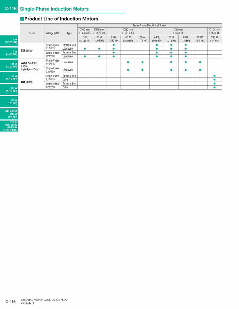
■Product Line of Induction Motors
Series Voltage (VAC) Type
Motor Frame Size, Output Power
□60 mm(□2.36 in.)
□70 mm(□2.76 in.)
□80 mm(□3.15 in.)
□90 mm(□3.54 in.)
□104 mm(□4.09 in.)
6 W(1/125 HP)
15 W(1/50 HP)
25 W(1/30 HP)
40 W(1/19 HP)
60 W(1/12 HP)
40 W(1/19 HP)
60 W(1/12 HP)
90 W(1/8 HP)
150 W(1/5 HP)
200 W(1/4 HP)
K Series
Single-Phase 110/115
Terminal Box ● ● ● ●Lead Wire ● ● ● ● ● ●
Single-Phase 220/230
Terminal Box ● ● ● ●Lead Wire ● ● ● ● ● ●
World K Series2-Pole, High-Speed Type
Single-Phase 110/115
Lead Wire ● ● ● ● ●
Single-Phase 220/230
Lead Wire ● ● ● ● ●
BH Series
Single-Phase 110/115
Terminal Box ●Cable ●
Single-Phase 220/230
Terminal Box ●Cable ●

C-117
Standard AC Motors C-117
Constant
Speed
Motors
Overview,
Product
Series
Three-Phase Induction Motors
Single-PhaseInduction Motors
Reversible Motors
Electromagnetic Brake Motors
Clutch & Brake Motors
Low-Speed Synchronous Motors
Torque
Motors
Watertight,
Dust-Resistant
Motors
Right-Angle
Gearheads
Linear
Heads
Brake Pack
Accessories
Installation
CAD DataManuals
www.orientalmotor.com Technical Support
TEL: (800) 468-3982E-mail: [email protected]
■System Configuration
K Series Parallel Shaft Combination Type
Induction Motors
Capacitor (Included)
Capacitor Cap
(Included)
Example of System Confi guration●
Induction Motors
Parallel Shaft Combination
Type
Sold Separately
Mounting BracketFlexible
Couplings
4IK25UA-25A SOL4UAF MCL40F10F10$146.00 $27.00 $76.00
● The system configuration shown above is an example. Other combinations are also available.
AC Power Supply
(Main power supply)
Brake Pack
SB50W ➜ Page C-191
Peripheral Equipment (Sold separately)
Flexible Couplings
➜ Page C-201Mounting Brackets
➜ Page C-196Capacitor Mounting Bracket
➜ Page C-208
Accessories (Sold separately)

C-118
C-118 Single-Phase Induction Motors
ORIENTAL MOTOR GENERAL CATALOG 2015/2016
6 W
(1/125 HP)
15 W
(1/50 HP)
25 W
(1/30 HP)
40 W
(1/19 HP)
60 W
(1/12 HP)
90 W
(1/8 HP)
BH Series
200 W
(1/4 HP)
2-Pole High-Speed
40-150 W (1/19-1/5 HP)
■Product Number
●K Series
4 I K 25 UA T2 - 12.5 A① ② ③ ④ ⑤ ⑥ ⑧⑦
① Motor Frame Size2: 60 mm (2.36 in.) 3: 70 mm (2.76 in.) 4: 80 mm (3.15 in.) 5: 90 mm (3.54 in.)
② Motor Type I: Induction Motor③ Series K: K Series④ Output Power (W) (Example) 25: 25 W (1/30 HP)⑤ Power Supply Voltage UA: Single-Phase 110/115 VAC UC: Single-Phase 220/230 VAC⑥ T2: Terminal Box Type Blank: Lead Wire Type⑦ Gear Ratio Number: Gear Ratio of Combination Type⑧ A: Imperial
●Metric output shafts are available. See website for product names and drawings.
●World K Series 2-Pole/High-Speed Type
5 I K 60 A - BW 2 U① ② ③ ④ ⑥⑤ ⑧⑦
① Motor Frame Size 4: 80 mm (3.15 in.) 5: 90 mm (3.54 in.)② Motor Type I: Induction Motor③ Series K: K Series④ Output Power (W) (Example) 60: 60 W (1/12 HP)⑤ Motor Shaft Type A: Round Shaft
⑥ Power Supply Voltage/Number of Poles
BW: Single-Phase 110/115 VAC 2-Pole DW: Single-Phase 220/230 VAC 2-Pole
⑦ 2, 3: RoHS-Compliant
⑧ Included CapacitorU: For Single-Phase 110/115 VAC E: For Single-Phase 220/230 VAC
●The U and E at the end of the product name indicate that the unit includes a capacitor. These letters are not listed on the motor nameplate.When the motor is approved under various standards, the product name on the nameplate is the approved product name.(Example) Model: 5IK60A-BW2U ➜ Motor nameplate and product approved under various standards: 5IK60A-BW2
●BH Series
BH I 6 2 F T - 100 RH① ⑧⑦② ③ ④ ⑥⑤
① Series BH: BH Series② Motor Type I: Induction Motor③ Motor Frame Size 6: 104 mm (4.09 in.)④ Output Power (W) (Example) 2: 200 W (1/4 HP)⑤ Power Supply Voltage F: Single-Phase 110/115 VAC E: Single-Phase 220/230 VAC ⑥ T: Terminal Box Type Blank: Cable Type⑦ Gear Ratio, Motor Shaft Type A: Round Shaft Type Number: Gear Ratio of Combination Type
⑧Type of Gearhead(Combination type only)
RH: Right-Angle, Hollow Shaft Type RA: Right-Angle, Solid Shaft Type Blank: Parallel Shaft Type

C-119
Standard AC Motors C-119
Constant
Speed
Motors
Overview,
Product
Series
Three-Phase Induction Motors
Single-PhaseInduction Motors
Reversible Motors
Electromagnetic Brake Motors
Clutch & Brake Motors
Low-Speed Synchronous Motors
Torque
Motors
Watertight,
Dust-Resistant
Motors
Right-Angle
Gearheads
Linear
Heads
Brake Pack
Accessories
Installation
CAD DataManuals
www.orientalmotor.com Technical Support
TEL: (800) 468-3982E-mail: [email protected]
■General Specifications
●K SeriesItem Specifications
Insulation Resistance 100 MΩ or more when 500 VDC megger is applied between the windings and the case after rated operation under normal ambient temperature and humidity.Dielectric Strength Sufficient to withstand 1.5 kVAC at 60 Hz applied between the windings and the case for 1 minute after rated operation under normal ambient temperature and humidity.Temperature Rise Temperature rise of windings are 80˚C (144˚F) or less measured by the resistance change method after rated operation under normal ambient temperature and humidity.Thermal Class 130 (B)
Overheat Protection6 W (1/125 HP) type has impedance protection.Other Types Built-In thermal protector (automatic return type) Open: 130±5˚C (266±9˚F), Close: 85±20˚C (185±36˚F)
Ambient Temperature −10∼+40˚C (+14∼+104˚F) (non-freezing)Ambient Humidity 85% or less (non-condensing)
Degree of ProtectionTerminal Box Type: 25 W (1/30 HP), 40 W (1/19 HP) IP66✽ (excluding the installation surface of the round shaft type) : 60 W (1/12 HP), 90 W (1/8 HP) IP54 (excluding the installation surface of the round shaft type)Lead Wire Type: IP20
✽Refer to page C-115 for the materials and surface treatments.
●World K Series 2-Pole/High-Speed TypeItem Specifications
Insulation Resistance 100 MΩ or more when 500 VDC megger is applied between the windings and the case after rated operation under normal ambient temperature and humidity.
Dielectric StrengthSufficient to withstand 1.5 kVAC at 50 Hz or 60 Hz applied between the windings and the case for 1 minute after rated operation under normal ambient temperature and humidity.
Temperature RiseTemperature rise of windings are 80˚C (144˚F) or less measured by the resistance change method after rated operation under normal ambient temperature and humidity with connecting a gearhead or equivalent heat radiation plate✽.
Thermal Class 130 (B)Overheat Protection Built-In thermal protector (automatic return type) Open: 130±5˚C (266±9˚F), Close: 82±15˚C (179.6±27˚F)Ambient Temperature −10∼+40˚C (+14∼+104˚F) (non-freezing)Ambient Humidity 85% or less (non-condensing)Degree of Protection IP20
✽Heat radiation plate (Material: Aluminum)
Motor Type Size: mm (in.) Thickness: mm (in.)2-Pole, High-Speed 4IK40 Type, 4IK60 Type 135×135 (5.31×5.31)
5 (0.20)2-Pole, High-Speed 5IK60 Type 165×165 (6.50×6.50)2-Pole/High-Speed 5IK90 Type, 51K150 Type 200×200 (7.87×7.87)
●BH SeriesItem Specifications
Insulation Resistance 100 MΩ or more when 500 VDC megger is applied between the windings and the case after rated operation under normal ambient temperature and humidity.
Dielectric StrengthSufficient to withstand 1.5 kVAC at 50 Hz or 60 Hz applied between the windings and the case for 1 minute after rated operation under normal ambient temperature and humidity.
Temperature RiseTemperature rise of windings are 70˚C (126˚F) or less measured by the resistance change method after rated operation under normal ambient temperature and humidity with connecting a gearhead or equivalent heat radiation plate✽.
Thermal Class 130 (B)Overheat Protection Built-in thermal protector (automatic return type) Open: 150±5˚C, (302±9˚F), Close: 96±15˚C (204.8±27˚F)Ambient Temperature −10∼+40˚C (+14∼+104˚F) (non-freezing)Ambient Humidity 85% or less (non-condensing)
Degree of ProtectionTerminal Box Type: IP54 (excluding the installation surface of the round shaft type)Cable Type: IP40
✽ Heat radiation plate: 230×230 mm (9.06×9.06 in.), Thickness: 5 mm (0.20 in.) (Material: Aluminum)

C-120
C-120 Single-Phase Induction Motors
ORIENTAL MOTOR GENERAL CATALOG 2015/2016
Page Features C-115 / System Configuration C-117 / Specifications C-119
Connection Diagrams C-132 / Motor and Gearhead Combinations C-133
6 W
(1/125 HP)
2-Pole High-Speed
40-150 W (1/19-1/5 HP)
BH Series
200 W
(1/4 HP)
90 W
(1/8 HP)
60 W
(1/12 HP)
40 W
(1/19 HP)
25 W
(1/30 HP)
15 W
(1/50 HP)
K Series
6 W (1/125 HP)Frame Size: □60 mm (□2.36 in.)
■Specifications – Continuous Rating
Product Name Output Power Voltage Frequency Current Starting Torque Rated Torque Rated Speed Capacitor Overheat Protection
DeviceLead Wire Type W (HP) VAC Hz A mN·m (oz-in.) mN·m (oz-in.) r/min μF
2IK6UA-□A 6 (1/125)Single-Phase 110
600.185 40 (5.6) 41 (5.8) 1450
2.5ZP
Single-Phase 115 0.189 40 (5.6) 41 (5.8) 1450
2IK6UC-□A 6 (1/125)Single-Phase 220
600.093 40 (5.6) 41 (5.8) 1450
0.6Single-Phase 230 0.096 40 (5.6) 41 (5.8) 1450
●The values in the table are characteristics for the motor only.ZP: These products are impedance protected.
■Product Line
Motor and gearhead are delivered pre-assembled. The combination of motors and gearheads can be changed and they are also available separately.In addition, the gearhead can be removed and the assembly position can be changed in 90° increments.
Combination Type Motor Gearhead
= +Combination
Type
●Combination Type Price includes motor and gearhead.
Product Name Gear Ratio List Price
2IK6UA- □ A
5, 6, 7.5, 9, 12.5, 15, 18 $121.0025, 30, 36 $127.00
50, 60, 75, 90, 100, 120, 150, 180 $134.00250, 300, 360 $180.00
2IK6UC- □ A
5, 6, 7.5, 9, 12.5, 15, 18 $124.0025, 30, 36 $130.00
50, 60, 75, 90, 100, 120, 150, 180 $137.00250, 300, 360 $183.00
The following items are included with each product.
Motor, Gearhead, Capacitor, Capacitor Cap, Installation Screws, Parallel Key, Operating Manual
●A number indicating the gear ratio is entered where the box □ is located within the product name.

C-121
Standard AC Motors C-121
Constant
Speed
Motors
Overview,
Product
Series
Three-Phase Induction Motors
Single-PhaseInduction Motors
Reversible Motors
Electromagnetic Brake Motors
Clutch & Brake Motors
Low-Speed Synchronous Motors
Torque
Motors
Watertight,
Dust-Resistant
Motors
Right-Angle
Gearheads
Linear
Heads
Brake Pack
Accessories
Installation
CAD DataManuals
www.orientalmotor.com Technical Support
TEL: (800) 468-3982E-mail: [email protected]
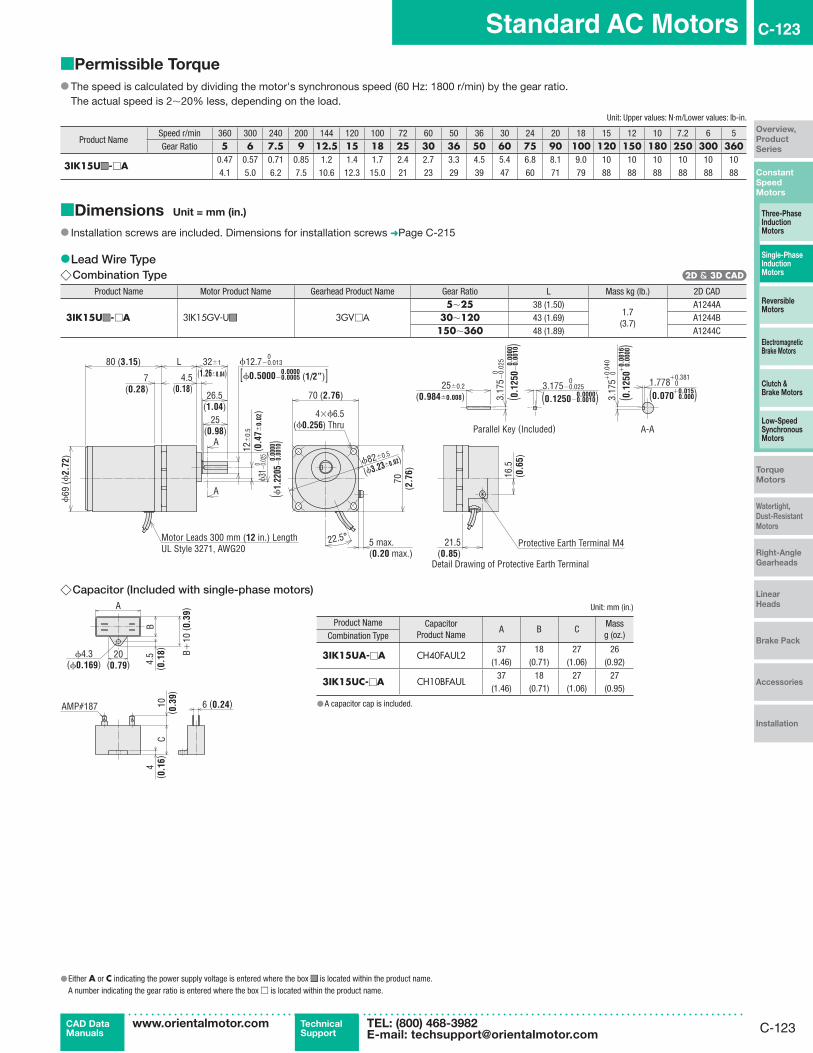
■Permissible Torque
● The speed is calculated by dividing the motor's synchronous speed (60 Hz: 1800 r/min) by the gear ratio.The actual speed is 2∼20% less, depending on the load.
Unit: Upper values: N·m/Lower values: lb-in.
Product NameSpeed r/min 360 300 240 200 144 120 100 72 60 50 36 30 24 20 18 15 12 10 7.2 6 5Gear Ratio 5 6 7.5 9 12.5 15 18 25 30 36 50 60 75 90 100 120 150 180 250 300 360
2IK6U ■ ■ - □ A0.18 0.22 0.28 0.33 0.46 0.55 0.66 0.92 1.1 1.3 1.8 2.1 2.6 3.2 3.5 4.2 5.0 6 6 6 61.59 1.94 2.4 2.9 4.0 4.8 5.8 8.1 9.7 11.5 15.9 18.5 23 28 30 37 44 53 53 53 53
■Dimensions Unit = mm (in.)
● Installation screws are included. Dimensions for installation screws ➜ Page C-215
●Lead Wire Type ◇Combination Type
Product Name Motor Product Name Gearhead Product Name Gear Ratio L Mass kg (lb.) 2D CAD
2IK6U ■ ■ - □ A 2IK6GV-U ■ ■ 2GV □A5∼25 34 (1.34)
1.2(2.6)
A1243A30∼120 38 (1.50) A1243B
150∼360 43 (1.69) A1243C
7(0.28)
ϕ60
(ϕ2.
36)
75 (2.95)
25(0.98)
10±
0.5
(0.3
9±0.
02)
4(0.16)
[ϕ0.3750−0.0005 (3/8”)]0
A
A
60 (2.36)60
(2.3
6)
ϕ70±0.5
(ϕ2.76±0.02)
5 max.(0.20 max.)
22.5° 21.5 (0.85)
15.5
(0
.61)
2.383−0.025
(0.0938−0.0010)0
0.00002.38
3−0.
025
( 0.09
38−
0.00
10)
0
25±0.2
(0.984±0.008)1.321(0.052 )
+0.381
+0.01502.38
3 0
( 0.09
38
)+
0.04
0
+0.
0016
32±1L
ϕ23
−0.
021
0
0.00
00
0.0000
0.00
00
(1.26±0.04)
0.0000
0
0.00
00
ϕ9.525−0.013
( ϕ0.
9055
−0.
0008
)
26.5(1.04)
Detail Drawing of Protective Earth Terminal
Protective Earth Terminal M4
Motor Leads 300 mm (12 in.) LengthUL Style 3271, AWG20
Parallel Key (Included) A-A4×ϕ4.5
(ϕ0.177) Thru
●Either A or C indicating the power supply voltage is entered where the box ■ ■ is located within the product name.A number indicating the gear ratio is entered where the box □ is located within the product name.
◇Capacitor (Included with single-phase motors)
ϕ4.3(ϕ0.169)
20(0.79)
A
C
B +10
( 0.3
9)
B4.
5( 0
.18)
4( 0
.16)
10( 0
.39)
6 (0.24)AMP#187
Unit: mm (in.)
Product Name CapacitorProduct Name
A B CMassg (oz.)Combination Type
2IK6UA-□A CH25FAUL231 17 27 21
(1.22) (0.67) (1.06) (0.74)
2IK6UC-□A CH06BFAUL31 14.5 23.5 18
(1.22) (0.57) (0.93) (0.64)
●A capacitor cap is included.

C-122
C-122 Single-Phase Induction Motors
ORIENTAL MOTOR GENERAL CATALOG 2015/2016
Page Features C-115 / System Configuration C-117 / Specifications C-119
Connection Diagrams C-132 / Motor and Gearhead Combinations C-133
2-Pole High-Speed
40-150 W (1/19-1/5 HP)
BH Series
200 W
(1/4 HP)
90 W
(1/8 HP)
60 W
(1/12 HP)
40 W
(1/19 HP)
25 W
(1/30 HP)
15 W
(1/50 HP)
6 W
(1/125 HP)
K Series
15 W (1/50 HP)Frame Size: □70 mm (□2.76 in.)
■Specifications – Continuous Rating
Product Name Output Power Voltage Frequency Current Starting Torque Rated Torque Rated Speed Capacitor Overheat Protection
DeviceLead Wire Type W (HP) VAC Hz A mN·m (oz-in.) mN·m (oz-in.) r/min μF
3IK15UA-□A 15 (1/50)Single-Phase 110
600.31 65 (9.2) 105 (14.9) 1450
4.0TP
Single-Phase 115 0.31 65 (9.2) 105 (14.9) 1450
3IK15UC-□A 15 (1/50)Single-Phase 220
600.154 65 (9.2) 105 (14.9) 1450
1.0Single-Phase 230 0.155 65 (9.2) 105 (14.9) 1450
●The values in the table are characteristics for the motor only.TP: This indicates that there is a built-in thermal protector (automatic return type). If a motor overheats for any reason, the thermal protector is activated and the motor is stopped.
When the motor temperature drops, the thermal protector closes and the motor restarts automatically. Be sure to turn the power supply off before inspecting.
■Product Line
Motor and gearhead are delivered pre-assembled. The combination of motors and gearheads can be changed and they are also available separately.In addition, the gearhead can be removed and the assembly position can be changed in 90° increments.
Combination Type Motor Gearhead
= +Combination
Type
●Combination Type Price includes motor and gearhead.
Product Name Gear Ratio List Price
3IK15UA- □A
5, 6, 7.5, 9, 12.5, 15, 18 $132.0025, 30, 36 $138.00
50, 60, 75, 90, 100, 120, 150, 180 $145.00250, 300, 360 $189.00
3IK15UC- □A
5, 6, 7.5, 9, 12.5, 15, 18 $134.0025, 30, 36 $140.00
50, 60, 75, 90, 100, 120, 150, 180 $147.00250, 300, 360 $191.00
The following items are included with each product.
Motor, Gearhead, Capacitor, Capacitor Cap, Installation Screws, Parallel Key, Operating Manual
●A number indicating the gear ratio is entered where the box □ is located within the product name.
C-123
Standard AC Motors C-123
Constant
Speed
Motors
Overview,
Product
Series
Three-Phase Induction Motors
Single-PhaseInduction Motors
Reversible Motors
Electromagnetic Brake Motors
Clutch & Brake Motors
Low-Speed Synchronous Motors
Torque
Motors
Watertight,
Dust-Resistant
Motors
Right-Angle
Gearheads
Linear
Heads
Brake Pack
Accessories
Installation
CAD DataManuals
www.orientalmotor.com Technical Support
TEL: (800) 468-3982E-mail: [email protected]
■Permissible Torque
● The speed is calculated by dividing the motor's synchronous speed (60 Hz: 1800 r/min) by the gear ratio.The actual speed is 2∼20% less, depending on the load.
Unit: Upper values: N·m/Lower values: lb-in.
Product NameSpeed r/min 360 300 240 200 144 120 100 72 60 50 36 30 24 20 18 15 12 10 7.2 6 5Gear Ratio 5 6 7.5 9 12.5 15 18 25 30 36 50 60 75 90 100 120 150 180 250 300 360
3IK15U ■ ■ - □A0.47 0.57 0.71 0.85 1.2 1.4 1.7 2.4 2.7 3.3 4.5 5.4 6.8 8.1 9.0 10 10 10 10 10 104.1 5.0 6.2 7.5 10.6 12.3 15.0 21 23 29 39 47 60 71 79 88 88 88 88 88 88
■Dimensions Unit = mm (in.)
● Installation screws are included. Dimensions for installation screws ➜Page C-215
●Lead Wire Type ◇Combination Type
Product Name Motor Product Name Gearhead Product Name Gear Ratio L Mass kg (lb.) 2D CAD
3IK15U ■ ■ - □A 3IK15GV-U ■ ■ 3GV □A5∼25 38 (1.50)
1.7(3.7)
A1244A30∼120 43 (1.69) A1244B
150∼360 48 (1.89) A1244C
L
7(0.28)
80 (3.15)
25(0.98)
4.5(0.18)
26.5(1.04)
70 (2.76)70
(2.7
6)
5 max.(0.20 max.)
21.5 (0.85)
16.5
(0.6
5)
A
A
22.5°
ϕ69
(ϕ2.
72)
12±
0.5
(0.4
7±0.
02)
ϕ12.7−0.0130.0000
032±1
ϕ 31 −
0.025
0 ϕ82±0.5
3.175−0.025
3.17
5−0.
025
0
25±0.2
(0.984±0.008) (0.070 0.000)+0.381
+0.015
3.17
5 0
+0.
040
+0.
0016
0.00
00
0.00
00
(ϕ3.23±0.02)
(1.26±0.04)
(ϕ 1.2
205 −
0.00
10)
[ϕ0.5000−0.0005 (1/2”)]
(0.12
50−
0.00
10)
(0.1250−0.0010)0.0000
0 1.778 0
(0.12
50 0
.000
0)
Detail Drawing of Protective Earth Terminal
Protective Earth Terminal M4Motor Leads 300 mm (12 in.) LengthUL Style 3271, AWG20
4×ϕ6.5(ϕ0.256) Thru Parallel Key (Included) A-A
◇Capacitor (Included with single-phase motors)
ϕ4.3(ϕ0.169)
20(0.79)
A
C
B +10
( 0.3
9)
B4.
5( 0
.18)
4( 0
.16)
10( 0
.39)
6 (0.24)AMP#187
●Either A or C indicating the power supply voltage is entered where the box ■ ■ is located within the product name.A number indicating the gear ratio is entered where the box □ is located within the product name.
Unit: mm (in.)
Product Name CapacitorProduct Name
A B CMassg (oz.)Combination Type
3IK15UA-□A CH40FAUL237 18 27 26
(1.46) (0.71) (1.06) (0.92)
3IK15UC-□A CH10BFAUL37 18 27 27
(1.46) (0.71) (1.06) (0.95)
●A capacitor cap is included.

C-124
C-124 Single-Phase Induction Motors
ORIENTAL MOTOR GENERAL CATALOG 2015/2016
Page Features C-115 / System Configuration C-117 / Specifications C-119
Connection Diagrams C-132 / Motor and Gearhead Combinations C-133
6 W
(1/125 HP)
15 W
(1/50 HP)
40 W
(1/19 HP)
60 W
(1/12 HP)
90 W
(1/8 HP)
BH Series
200 W
(1/4 HP)
2-Pole High-Speed
40-150 W (1/19-1/5 HP)
25 W
(1/30 HP)
K Series
25 W (1/30 HP)Frame Size: □80 mm (□3.15 in.)
■ Specifications – Continuous Rating
Product Name Output Power Voltage Frequency Current Starting Torque Rated Torque Rated Speed Capacitor Overheat Protection
DeviceTerminal Box Type Lead Wire Type W (HP) VAC Hz A mN·m (oz-in.) mN·m (oz-in.) r/min μF
4IK25UAT2-□A 4IK25UA-□A 25 (1/30)Single-Phase 110
600.44 120 (17.0) 170 (24) 1450
6.0TP
Single-Phase 115 0.43 120 (17.0) 170 (24) 1450
4IK25UCT2-□A 4IK25UC-□A 25 (1/30)Single-Phase 220
600.22 110 (15.6) 170 (24) 1450
1.5Single-Phase 230 0.22 120 (17.0) 170 (24) 1450
●The values in the table are characteristics for the motor only.TP: This indicates that there is a built-in thermal protector (automatic return type). If a motor overheats for any reason, the thermal protector is activated and the motor is stopped.
When the motor temperature drops, the thermal protector closes and the motor restarts automatically. Be sure to turn the power supply off before inspecting.
■Product Line
Motor and gearhead are delivered pre-assembled. The combination of motors and gearheads can be changed and they are also available separately.In addition, the gearhead can be removed and the assembly position can be changed in 90° increments.
Combination Type Motor Gearhead
= +Combination
Type
●Combination Type Price includes motor and gearhead.
◇Terminal Box TypeProduct Name Gear Ratio List Price
4IK25UAT2- □A
5, 6, 7.5, 9, 12.5, 15, 18 $162.0025, 30, 36 $168.00
50, 60, 75, 90, 100, 120, 150, 180 $175.00250, 300, 360 $222.00
4IK25UCT2- □A
5, 6, 7.5, 9, 12.5, 15, 18 $165.0025, 30, 36 $171.00
50, 60, 75, 90, 100, 120, 150, 180 $178.00
250, 300, 360 $225.00
◇Lead Wire TypeProduct Name Gear Ratio List Price
4IK25UA-□A
5, 6, 7.5, 9, 12.5, 15, 18 $140.0025, 30, 36 $146.00
50, 60, 75, 90, 100, 120, 150, 180 $153.00250, 300, 360 $200.00
4IK25UC-□A
5, 6, 7.5, 9, 12.5, 15, 18 $144.0025, 30, 36 $150.00
50, 60, 75, 90, 100, 120, 150, 180 $157.00
250, 300, 360 $204.00
Terminal Box Type Lead Wire Type
●Either A or C indicating the power supply voltage is entered where the box ■ ■ is located within the product name. ●A code (T2) indicating the terminal box type is entered where the box ■ ■ is located within the product name.A number indicating the gear ratio is entered where the box □ is located within the product name.
The following items are included with each product.
Motor, Gearhead, Capacitor, Capacitor Cap, Installation Screws, Parallel Key, Operating Manual
■Permissible Torque ● The speed is calculated by dividing the motor's synchronous speed (60 Hz: 1800 r/min) by the gear ratio.The actual speed is 2∼20% less, depending on the load.
Unit: Upper values: N·m/Lower values: lb-in.
Product NameSpeed r/min 360 300 240 200 144 120 100 72 60 50 36 30 24 20 18 15 12 10 7.2 6 5Gear Ratio 5 6 7.5 9 12.5 15 18 25 30 36 50 60 75 90 100 120 150 180 250 300 360
4IK25U ■ ■ ■ ■ - □A0.77 0.92 1.1 1.4 1.9 2.3 2.8 3.8 4.4 5.3 7.3 8.8 11.0 13.2 14.6 16 16 16 16 16 166.8 8.1 9.7 12.3 16.8 20 24 33 38 46 64 77 97 116 129 141 141 141 141 141 141
C-125
Standard AC Motors C-125
Constant
Speed
Motors
Overview,
Product
Series
Three-Phase Induction Motors
Single-PhaseInduction Motors
Reversible Motors
Electromagnetic Brake Motors
Clutch & Brake Motors
Low-Speed Synchronous Motors
Torque
Motors
Watertight,
Dust-Resistant
Motors
Right-Angle
Gearheads
Linear
Heads
Brake Pack
Accessories
Installation
CAD DataManuals
www.orientalmotor.com Technical Support
TEL: (800) 468-3982E-mail: [email protected]
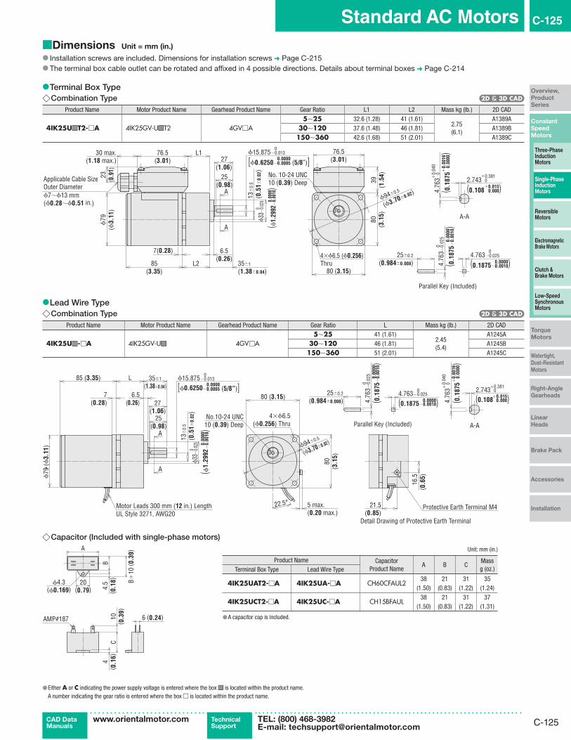
■Dimensions Unit = mm (in.)
● Installation screws are included. Dimensions for installation screws ➜ Page C-215 ● The terminal box cable outlet can be rotated and affixed in 4 possible directions. Details about terminal boxes ➜ Page C-214
●Terminal Box Type ◇Combination Type
Product Name Motor Product Name Gearhead Product Name Gear Ratio L1 L2 Mass kg (lb.) 2D CAD
4IK25U ■ ■ T2- □A 4IK25GV-U ■ ■ T2 4GV □A5∼25 32.6 (1.28) 41 (1.61)
2.75(6.1)
A1389A30∼120 37.6 (1.48) 46 (1.81) A1389B150∼360 42.6 (1.68) 51 (2.01) A1389C
ϕ79
(ϕ3.
11)
(1.06)25
(0.98)
80(3
.15)
A
A
ϕ94±0.5
(ϕ3.70±0.02)13±
0.5
(0.5
1±0.
02)
ϕ15.875−0.013
[ϕ0.6250−0.0005 (5/8”)] 0
ϕ33
−0.0
250
25±0.2
(0.984±0.008) ( 0.18
75−
0.00
10)
0.00
00
4.763−0.025
(0.1875−0.0010)0
80 (3.15)
7(0.28)
85(3.35)
L2
6.5(0.26)
35±1
(1.38±0.04)
76.5(3.01)
39( 1
.54)
76.5(3.01)
30 max.(1.18 max.)
23(0
.91)
L1 0.0000
0.0000
4.76
3 0
( 0.18
75
0.0
000)
+
0.04
0
+
0.00
16
2.743 0(0.108 0.000)
+0.381
+0.015
27
( ϕ 1.2
992−
0.00
10)
0.
0000
4.76
3−0.
025
0
A-A
Parallel Key (Included)
No. 10-24 UNC 10 (0.39) Deep Applicable Cable Size
Outer Diameterϕ7∼ϕ13 mm (ϕ0.28∼ϕ0.51 in.)
4×ϕ6.5 (ϕ0.256) Thru
●Lead Wire Type ◇Combination Type
Product Name Motor Product Name Gearhead Product Name Gear Ratio L Mass kg (lb.) 2D CAD
4IK25U ■ ■ - □A 4IK25GV-U ■ ■ 4GV □A5∼25 41 (1.61)
2.45(5.4)
A1245A30∼120 46 (1.81) A1245B
150∼360 51 (2.01) A1245C
7(0.28)
ϕ79
(ϕ3.
11)
85 (3.35) L
27(1.06)
6.5(0.26)
35±1
(1.38±0.04)
25(0.98)
80(3
.15)
22.5°
80 (3.15)
21.5(0.85)
16.5
(0.6
5)
A
A
ϕ94±0.5
(ϕ3.70±0.02)
5 max.(0.20 max.)
13±
0.5
(0.5
1±0.
02)
ϕ15.875−0.0130
ϕ33
−0.
025
0
25±0.2
(0.984±0.008) 4.76
3−0.
025
2.743 0 +0.381
4.76
3 0
0.0000 0
0.00
00
+0.
040
+0.
0016
4.763−0.025 +0.015(0.18
75
0.0
000)
(0.108 0.000)(0.18
75−
0.00
10)
(ϕ1.
2992
−0.
0010
)0.
0000
[ϕ0.6250−0.0005 (5/8”)](0.1875−0.0010)0.0000
0
Protective Earth Terminal M4
A-AParallel Key (Included)
Motor Leads 300 mm (12 in.) LengthUL Style 3271, AWG20
4×ϕ6.5 (ϕ0.256) Thru
Detail Drawing of Protective Earth Terminal
No.10-24 UNC10 (0.39) Deep
◇Capacitor (Included with single-phase motors)
ϕ4.3(ϕ0.169)
20(0.79)
A
C
B +10
( 0.3
9)
B4.
5( 0
.18)
4( 0
.16)
10( 0
.39)
6 (0.24)AMP#187
Unit: mm (in.)
Product Name CapacitorProduct Name
A B CMassg (oz.)Terminal Box Type Lead Wire Type
4IK25UAT2-□A 4IK25UA-□A CH60CFAUL238 21 31 35
(1.50) (0.83) (1.22) (1.24)
4IK25UCT2-□A 4IK25UC-□A CH15BFAUL38 21 31 37
(1.50) (0.83) (1.22) (1.31)
●A capacitor cap is included.
●Either A or C indicating the power supply voltage is entered where the box ■ ■ is located within the product name.A number indicating the gear ratio is entered where the box □ is located within the product name.

C-126
C-126 Single-Phase Induction Motors
ORIENTAL MOTOR GENERAL CATALOG 2015/2016
Page Features C-115 / System Configuration C-117 / Specifications C-119
Connection Diagrams C-132 / Motor and Gearhead Combinations C-133
40 W
(1/19 HP)
6 W
(1/125 HP)
15 W
(1/50 HP)
25 W
(1/30 HP)
60 W
(1/12 HP)
90 W
(1/8 HP)
BH Series
200 W
(1/4 HP)
2-Pole High-Speed
40-150 W (1/19-1/5 HP)
K Series
40 W (1/19 HP)Frame Size: □90 mm (□3.54 in.)
■ Specifications – Continuous Rating
Product Name Output Power Voltage Frequency Current Starting Torque Rated Torque Rated Speed Capacitor Overheat Protection
DeviceTerminal Box Type Lead Wire Type W (HP) VAC Hz A mN·m (oz-in.) mN·m (oz-in.) r/min μF
5IK40UAT2-□A 5IK40UA-□A 40 (1/19)Single-Phase 110
600.66 200 (28) 260 (36) 1500
9.0 TP
Single-Phase 115 0.65 200 (28) 260 (36) 1500
5IK40UCT2-□A 5IK40UC-□A 40 (1/19)Single-Phase 220
600.33 200 (28) 260 (36) 1500
2.0 Single-Phase 230 0.32 200 (28) 260 (36) 1500
●The values in the table are characteristics for the motor only.TP: This indicates that there is a built-in thermal protector (automatic return type). If a motor overheats for any reason, the thermal protector is activated and the motor is stopped.
When the motor temperature drops, the thermal protector closes and the motor restarts automatically. Be sure to turn the power supply off before inspecting.
■ Product Line
Motor and gearhead are delivered pre-assembled. The combination of motors and gearheads can be changed and they are also available separately.In addition, the gearhead can be removed and the assembly position can be changed in 90° increments.
Combination Type Motor Gearhead
= +Combination
Type
●Combination Type Price includes motor and gearhead.
◇Terminal Box TypeProduct Name Gear Ratio List Price
5IK40UAT2- □A
5, 6, 7.5, 9, 12.5, 15, 18 $191.0025, 30, 36 $198.00
50, 60, 75, 90, 100, 120, 150, 180 $205.00250, 300 $283.00
5IK40UCT2- □A
5, 6, 7.5, 9, 12.5, 15, 18 $194.0025, 30, 36 $201.00
50, 60, 75, 90, 100, 120, 150, 180 $208.00
250, 300 $286.00
◇Lead Wire TypeProduct Name Gear Ratio List Price
5IK40UA-□A
5, 6, 7.5, 9, 12.5, 15, 18 $169.0025, 30, 36 $176.00
50, 60, 75, 90, 100, 120, 150, 180 $183.00250, 300 $261.00
5IK40UC-□A
5, 6, 7.5, 9, 12.5, 15, 18 $173.0025, 30, 36 $180.00
50, 60, 75, 90, 100, 120, 150, 180 $187.00
250, 300 $265.00
Terminal Box Type Lead Wire Type
●Either A or C indicating the power supply voltage is entered where the box ■ ■ is located within the product name. ●A code (T2) indicating the terminal box type is entered where the box ■ ■ is located within the product name.A number indicating the gear ratio is entered where the box □ is located within the product name.
The following items are included with each product.
Motor, Gearhead, Capacitor, Capacitor Cap, Installation Screws, Parallel Key, Operating Manual
■Permissible Torque ● The speed is calculated by dividing the motor's synchronous speed (60 Hz: 1800 r/min) by the gear ratio.The actual speed is 2∼20% less, depending on the load.
Unit: Upper values: N·m/Lower values: lb-in.
Product NameSpeed r/min 360 300 240 200 144 120 100 72 60 50 36 30 24 20 18 15 12 10 7.2 6Gear Ratio 5 6 7.5 9 12.5 15 18 25 30 36 50 60 75 90 100 120 150 180 250 300
5IK40U ■ ■ ■ ■ - □A1.2 1.4 1.8 2.1 2.9 3.5 4.2 5.6 6.7 8.0 11.2 13.4 16.8 20.1 22.4 25.3 30 30 30 3010.6 12.3 15.9 18.5 25 30 37 49 59 70 99 118 148 177 198 220 260 260 260 260

C-127
Standard AC Motors C-127
Constant
Speed
Motors
Overview,
Product
Series
Three-Phase Induction Motors
Single-PhaseInduction Motors
Reversible Motors
Electromagnetic Brake Motors
Clutch & Brake Motors
Low-Speed Synchronous Motors
Torque
Motors
Watertight,
Dust-Resistant
Motors
Right-Angle
Gearheads
Linear
Heads
Brake Pack
Accessories
Installation
CAD DataManuals
www.orientalmotor.com Technical Support
TEL: (800) 468-3982E-mail: [email protected]
■Dimensions Unit = mm (in.)
● Installation screws are included. Dimensions for installation screws ➜ Page C-215 ● The terminal box cable outlet can be rotated and affixed in 4 possible directions. Details about terminal boxes ➜ Page C-214
●Terminal Box Type ◇Combination Type
Product Name Motor Product Name Gearhead Product Name Gear Ratio L1 L2 Mass kg (lb.) 2D CAD
5IK40U ■ ■ T2- □A 5IK40GV-U ■ ■ T2 5GV □A5∼18 36.6 (1.44) 45 (1.77)
4.3(9.5)
A1390A25∼100 49.6 (1.95) 58 (2.28) A1390B
120∼300 55.6 (2.19) 64 (2.52) A1390C
7.5(0.30)
ϕ89
(ϕ3.
50)
105(4.13)
42±1
(1.65±0.04)
34(1.34)
5 (0.20)
25(0.98)
A
A
90(3
.54)
(0.984±0.008)
2.692+0.381
0
4.76
3+0.
040
0
90(3.54)
L218
±0.
5
(0.7
1±0.
02)
ϕ19.050−0.013 0
ϕ39
−0.
025
0
( 0.18
75−
0.00
10)
0
4.763−0.025
(0.1875−0.0010)0.0000
0
30 max.(1.18 max.)
76.5 (3.01)L176.5 (3.01)
23(0
.91)
39(1
.54)
0.00
00
(0.106+0.015
0.000)( 0.18
75+
0.00
160.
0000
)
25±0.2
ϕ104±0.5
(ϕ4.09±0.02)
4.76
3−0.
025( ϕ
1.53
54−
0.00
10)
0.00
00
[ϕ0.7500−0.0005 (3/4”)] 0.0000
A-A
Parallel Key (Included)
No. 12-24 UNC12 (0.47) Deep
Applicable Cable SizeOuter Diameterϕ7∼ϕ13 mm (ϕ0.28∼ϕ0.51 in.)
4×ϕ8.5 (ϕ0.335) Thru
●Lead Wire Type ◇Combination Type
Product Name Motor Product Name Gearhead Product Name Gear Ratio L Mass kg (lb.) 2D CAD
5IK40U ■■-□A 5IK40GV-U ■■ 5GV □A5∼18 45 (1.77)
4.0(8.8)
A1247A25∼100 58 (2.28) A1247B
120∼300 64 (2.52) A1247C
7.5(0.30)
ϕ89
(ϕ3.
50)
105 (4.13) 42±1
(1.65±0.04)34
(1.34)
5(0.20)
25(0.98)
A
A 90 (3
.54)
21.5(0.85)
16.5
(0.6
5)
22.5° 5 max.(0.20 max.)
90 (3.54)
ϕ104±0.5
(ϕ4.09±0.02)
L
18±
0.5
(0.7
1±0.
02)
ϕ19.050−0.013
[ϕ0.7500−0.0005 (3/4”)]0
ϕ39
−0.
025
(ϕ1.
5354
−0.
0010
)0
0.0000
0.00
00
4.763−0.025
(0.1875−0.0010)0
0.0000
04.
763−
0.02
5
(0.18
75−
0.00
10)
0.00
0025±0.2
(0.984±0.008)
2.692 0
(0.106 0.000)+0.381
+0.015
4.76
3
0
(0.18
75
0.0
000)
+0.
040
+0.
0016
Protective Earth Terminal M4
A-AParallel Key (Included)
Motor Leads 300 mm (12 in.) LengthUL Style 3271, AWG20
4×ϕ8.5(ϕ0.335) Thru
Detail Drawing of Protective Earth Terminal
No.12-24 UNC12 (0.47) Deep
◇Capacitor (Included with single-phase motors)
ϕ4.3(ϕ0.169)
20(0.79)
A
C
B +10
( 0.3
9)
B4.
5( 0
.18)
4( 0
.16)
10( 0
.39)
6 (0.24)AMP#187
Unit: mm (in.)
Product Name CapacitorProduct Name
A B CMassg (oz.)Terminal Box Type Lead Wire Type
5IK40UAT2-□A 5IK40UA-□A CH90CFAUL248 22.5 31.5 45
(1.89) (0.89) (1.24) (1.59)
5IK40UCT2-□A 5IK40UC-□A CH20BFAUL48 19 29 36
(1.89) (0.75) (1.14) (1.27)
●A capacitor cap is included.
●Either A or C indicating the power supply voltage is entered where the box ■ ■ is located within the product name.A number indicating the gear ratio is entered where the box □ is located within the product name.
C-128
C-128 Single-Phase Induction Motors
ORIENTAL MOTOR GENERAL CATALOG 2015/2016
Page Features C-115 / System Configuration C-117 / Specifications C-119
Connection Diagrams C-132 / Motor and Gearhead Combinations C-133
60 W
(1/12 HP)
2-Pole High-Speed
40-150 W (1/19-1/5 HP)
BH Series
200 W
(1/4 HP)
90 W
(1/8 HP)
40 W
(1/19 HP)
25 W
(1/30 HP)
15 W
(1/50 HP)
6 W
(1/125 HP)
K Series
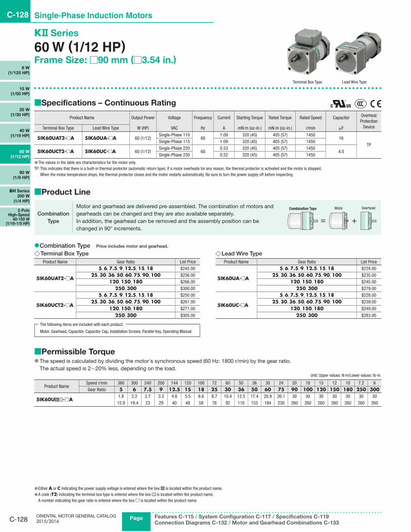
60 W (1/12 HP)Frame Size: □90 mm (□3.54 in.)
■ Specifications – Continuous Rating
Product Name Output Power Voltage Frequency Current Starting Torque Rated Torque Rated Speed Capacitor Overheat Protection
DeviceTerminal Box Type Lead Wire Type W (HP) VAC Hz A mN·m (oz-in.) mN·m (oz-in.) r/min μF
5IK60UAT2-□A 5IK60UA-□A 60 (1/12)Single-Phase 110
601.09 320 (45) 405 (57) 1450
16TP
Single-Phase 115 1.09 320 (45) 405 (57) 1450
5IK60UCT2-□A 5IK60UC-□A 60 (1/12)Single-Phase 220
600.53 320 (45) 405 (57) 1450
4.0Single-Phase 230 0.52 320 (45) 405 (57) 1450
●The values in the table are characteristics for the motor only.TP: This indicates that there is a built-in thermal protector (automatic return type). If a motor overheats for any reason, the thermal protector is activated and the motor is stopped.
When the motor temperature drops, the thermal protector closes and the motor restarts automatically. Be sure to turn the power supply off before inspecting.
■ Product Line
Motor and gearhead are delivered pre-assembled. The combination of motors and gearheads can be changed and they are also available separately.In addition, the gearhead can be removed and the assembly position can be changed in 90° increments.
Combination Type Motor Gearhead
= +Combination
Type
●Combination Type Price includes motor and gearhead.
◇Terminal Box TypeProduct Name Gear Ratio List Price
5IK60UAT2- □A
5, 6, 7.5, 9, 12.5, 15, 18 $245.0025, 30, 36, 50, 60, 75, 90, 100 $256.00
120, 150, 180 $266.00250, 300 $300.00
5IK60UCT2- □A
5, 6, 7.5, 9, 12.5, 15, 18 $250.0025, 30, 36, 50, 60, 75, 90, 100 $261.00
120, 150, 180 $271.00
250, 300 $305.00
◇Lead Wire TypeProduct Name Gear Ratio List Price
5IK60UA-□A
5, 6, 7.5, 9, 12.5, 15, 18 $224.0025, 30, 36, 50, 60, 75, 90, 100 $235.00
120, 150, 180 $245.00250, 300 $279.00
5IK60UC-□A
5, 6, 7.5, 9, 12.5, 15, 18 $228.0025, 30, 36, 50, 60, 75, 90, 100 $239.00
120, 150, 180 $249.00
250, 300 $283.00
Terminal Box Type Lead Wire Type
●Either A or C indicating the power supply voltage is entered where the box ■ ■ is located within the product name. ●A code (T2) indicating the terminal box type is entered where the box ■ ■ is located within the product name.A number indicating the gear ratio is entered where the box □ is located within the product name.
The following items are included with each product.
Motor, Gearhead, Capacitor, Capacitor Cap, Installation Screws, Parallel Key, Operating Manual
■Permissible Torque ● The speed is calculated by dividing the motor's synchronous speed (60 Hz: 1800 r/min) by the gear ratio.The actual speed is 2∼20% less, depending on the load.
Unit: Upper values: N·m/Lower values: lb-in.
Product NameSpeed r/min 360 300 240 200 144 120 100 72 60 50 36 30 24 20 18 15 12 10 7.2 6Gear Ratio 5 6 7.5 9 12.5 15 18 25 30 36 50 60 75 90 100 120 150 180 250 300
5IK60U ■ ■ ■ ■ - □A1.8 2.2 2.7 3.3 4.6 5.5 6.6 8.7 10.4 12.5 17.4 20.9 26.1 30 30 30 30 30 30 3015.9 19.4 23 29 40 48 58 76 92 110 153 184 230 260 260 260 260 260 260 260

C-129
Standard AC Motors C-129
Constant
Speed
Motors
Overview,
Product
Series
Three-Phase Induction Motors
Single-PhaseInduction Motors
Reversible Motors
Electromagnetic Brake Motors
Clutch & Brake Motors
Low-Speed Synchronous Motors
Torque
Motors
Watertight,
Dust-Resistant
Motors
Right-Angle
Gearheads
Linear
Heads
Brake Pack
Accessories
Installation
CAD DataManuals
www.orientalmotor.com Technical Support
TEL: (800) 468-3982E-mail: [email protected]
■Dimensions Unit = mm (in.)
● Installation screws are included. Dimensions for installation screws ➜ Page C-215 ● The terminal box cable outlet can be rotated and affixed in 4 possible directions. Details about terminal boxes ➜ Page C-214
●Terminal Box Type ◇Combination Type
Product Name Motor Product Name Gearhead Product Name Gear Ratio L1 L2 Mass kg (lb.) 2D CAD
5IK60U ■ ■ T2- □A 5IK60GVH-U ■ ■ T2 5GVH □A5∼18 36.6 (1.44) 45 (1.77)
4.5(9.9)
A1391A25∼100 49.6 (1.95) 58 (2.28) A1391B
120∼300 55.6 (2.19) 64 (2.52) A1391C
□90
(□3.
54)
25(0.98)
90(3.54)
90(3
.54)
34(1.34)
(0.984±0.008)
2.692+0.381
0
4.76
3+0.
040
0
(0.106+0.015
0.000)
18±
0.5
(0.7
1±0.
02)
ϕ39
−0.
025
0
4.76
3−0.
025
0
0
0.0000
A
A
ϕ104±0.5
(ϕ4.09±0.02)
7.5(0.30)120
(4.72)
5 (0.20)42±1
(1.65±0.04)L2
(1.18 max.)76.5 (3.01)
39(1
.54)
L176.5 (3.01)
23(0
.91)
[ϕ0.7500−0.0005 (3/4”)] 0
0.000030 max.
25±0.2
( ϕ1.
5354
−0.
0010
) 0.
0000
ϕ19.050−0.013
( 0.18
75+
0.00
160.
0000
)
( 0.18
750.
0000
−0.
0010
)
No. 12-24 UNC12 (0.47) Deep
A-A
Parallel Key (Included)
4×ϕ8.5 (ϕ0.335) Thru
Applicable Cable SizeOuter Diameterϕ7∼ϕ13 mm (ϕ0.28∼ϕ0.51 in.)
4.763−0.025
(0.1875−0.0010)
●Lead Wire Type ◇Combination Type
Product Name Motor Product Name Gearhead Product Name Gear Ratio L Mass kg (lb.) 2D CAD
5IK60U ■■-□A 5IK60GVH-U ■■ 5GVH □A5∼18 45 (1.77)
4.2(9.2)
A1249A25∼100 58 (2.28) A1249B
120∼300 64 (2.52) A1249C
7.5(0.30)
120 (4.72)
□90
(□3.
54)
5(0.20)
25(0.98)
90 (3.54)
90(3
.54)
22.5°5 max.(0.20 max.)
21.5(0.85)
16.5
(0.6
5)
42±1
(1.65±0.04)34
(1.34)
ϕ18
±0.
5
(0.7
1±0.
02)
ϕ39
−0.
025
0
L
A
A
ϕ104±0.5
(ϕ4.09±0.02)
4.763−0.025 0
0.0000
04.
763−
0.02
5 0.00
0025±0.2
(0.984±0.008)
2.692 0 +0.381
+0.015
ϕ19.050−0.0130.0000
0
[ϕ0.7500−0.0005 (3/4”)]
0.00
00(ϕ 1
.535
4 −0.
0010
)
4.76
3 0
+0.
040
+0.
0016
(0.18
75 0
.000
0)
(0.1875−0.0010)(0.18
75−
0.00
10)
(0.106 0.000)
Motor Leads 300 mm (12 in.) LengthUL Style 3271, AWG20
4×ϕ8.5 (ϕ0.335) Thru
No.12-24 UNC12 (0.47) Deep
A-AParallel Key (Included)
Detail Drawing of Protective Earth Terminal
Protective Earth Terminal M4
◇Capacitor (Included with single-phase motors)
6 (0.24)
A
CB
7( 0
.28)20
(0.79)
10( 0
.39)
AMP#187
ϕ4.3(ϕ0.169)
4( 0
.16)
B+15
( 0.5
9)
R10(R0.39)
Unit: mm (in.)
Product Name CapacitorProduct Name
A B CMassg (oz.)Terminal Box Type Lead Wire Type
5IK60UAT2-□A 5IK60UA-□A CH160CFAUL258 23.5 37 71
(2.28) (0.93) (1.46) (2.5)
5IK60UCT2-□A 5IK60UC-□A CH40BFAUL58 23.5 37 73
(2.28) (0.93) (1.46) (2.6)
●A capacitor cap is included.
●Either A or C indicating the power supply voltage is entered where the box ■ ■ is located within the product name.A number indicating the gear ratio is entered where the box □ is located within the product name.

C-130
C-130 Single-Phase Induction Motors
ORIENTAL MOTOR GENERAL CATALOG 2015/2016
Page Features C-115 / System Configuration C-117 / Specifications C-119
Connection Diagrams C-132 / Motor and Gearhead Combinations C-133
90 W
(1/8 HP)
2-Pole High-Speed
40-150 W (1/19-1/5 HP)
BH Series
200 W
(1/4 HP)
60 W
(1/12 HP)
40 W
(1/19 HP)
25 W
(1/30 HP)
15 W
(1/50 HP)
6 W
(1/125 HP)
K Series
90 W (1/8 HP)Frame Size: □90 mm (□3.54 in.)
■ Specifications – Continuous Rating
Product Name Output Power Voltage Frequency Current Starting Torque Rated Torque Rated Speed Capacitor Overheat Protection
DeviceTerminal Box Type Lead Wire Type W (HP) VAC Hz A mN·m (oz-in.) mN·m (oz-in.) r/min μF
5IK90UAT2-□A 5IK90UA-□A 90 (1/8)Single-Phase 110
601.44 450 (63) 585 (83) 1500
20TP
Single-Phase 115 1.44 450 (63) 585 (83) 1500
5IK90UCT2-□A 5IK90UC-□A 90 (1/8)Single-Phase 220
600.71 450 (63) 605 (85) 1450
5.0Single-Phase 230 0.71 450 (63) 605 (85) 1450
●The values in the table are characteristics for the motor only.TP: This indicates that there is a built-in thermal protector (automatic return type). If a motor overheats for any reason, the thermal protector is activated and the motor is stopped.
When the motor temperature drops, the thermal protector closes and the motor restarts automatically. Be sure to turn the power supply off before inspecting.
■ Product Line
Motor and gearhead are delivered pre-assembled. The combination of motors and gearheads can be changed and they are also available separately.In addition, the gearhead can be removed and the assembly position can be changed in 90° increments.
Combination Type Motor Gearhead
= +Combination
Type
●Combination Type Price includes motor and gearhead.
◇Terminal Box TypeProduct Name Gear Ratio List Price
5IK90UAT2- □A5, 6, 7.5, 9, 12.5, 15, 18 $265.00
25, 30, 36, 50, 60, $285.0075, 90, 100, 120, 150, 180 $295.00
5IK90UCT2- □A5, 6, 7.5, 9, 12.5, 15, 18 $269.00
25, 30, 36, 50, 60, $289.00
75, 90, 100, 120, 150, 180 $299.00
◇Lead Wire TypeProduct Name Gear Ratio List Price
5IK90UA-□A5, 6, 7.5, 9, 12.5, 15, 18 $243.00
25, 30, 36, 50, 60, $263.0075, 90, 100, 120, 150, 180 $273.00
5IK90UC-□A5, 6, 7.5, 9, 12.5, 15, 18 $248.00
25, 30, 36, 50, 60, $268.00
75, 90, 100, 120, 150, 180 $278.00
Terminal Box Type Lead Wire Type
●A code (T2) indicating the terminal box type is entered where the box ■ ■ is located within the product name.A number indicating the gear ratio is entered where the box □ is located within the product name.
The following items are included with each product.
Motor, Gearhead, Capacitor, Capacitor Cap, Installation Screws, Parallel Key, Operating Manual
■Permissible Torque ● The speed is calculated by dividing the motor's synchronous speed (60 Hz: 1800 r/min) by the gear ratio.The actual speed is 2∼20% less, depending on the load.
Unit: Upper values: N·m/Lower values: lb-in.
Product NameSpeed r/min 360 300 240 200 144 120 100 72 60 50 36 30 24 20 18 15 12 10Gear Ratio 5 6 7.5 9 12.5 15 18 25 30 36 50 60 75 90 100 120 150 180
5IK90UA ■ ■ - □A2.6 3.2 3.9 4.7 6.6 7.9 9.1 12.6 15.1 18.1 25.2 30.2 35.5 40 40 40 40 4023 28 34 41 58 69 80 111 133 160 220 260 310 350 350 350 350 350
5IK90UC ■ ■ - □A2.7 3.3 4.1 4.9 6.8 8.2 9.4 13.0 15.6 18.7 26.0 31.2 36.8 40 40 40 40 4023 29 36 43 60 72 83 115 138 165 230 270 320 350 350 350 350 350

C-131
Standard AC Motors C-131
Constant
Speed
Motors
Overview,
Product
Series
Three-Phase Induction Motors
Single-PhaseInduction Motors
Reversible Motors
Electromagnetic Brake Motors
Clutch & Brake Motors
Low-Speed Synchronous Motors
Torque
Motors
Watertight,
Dust-Resistant
Motors
Right-Angle
Gearheads
Linear
Heads
Brake Pack
Accessories
Installation
CAD DataManuals
www.orientalmotor.com Technical Support
TEL: (800) 468-3982E-mail: [email protected]
■Dimensions Unit = mm (in.)
● Installation screws are included. Dimensions for installation screws ➜ Page C-215 ● The terminal box cable outlet can be rotated and affixed in 4 possible directions. Details about terminal boxes ➜ Page C-214
●Terminal Box Type ◇Combination Type
Product Name Motor Product Name Gearhead Product Name Gear Ratio L1 L2 Mass kg (lb.) 2D CAD
5IK90U ■ ■ T2- □A 5IK90GVR-U ■ ■ T2 5GVR □A5∼15 36.6 (1.44) 45 (1.77)
5.0(11.0)
A1392A18∼36 49.6 (1.95) 58 (2.28) A1392B
50∼180 61.6 (2.43) 70 (2.76) A1392C
7.5 (0.30)135
(5.31)
□90
(□3.
54)
L2 42±1
(1.65±0.04)
5 (0.20)
25(0.98)
90(3
.54)
A
A
34(1.34)
18±
0.5
(0.7
1±0.
02)
[ϕ0.7500−0.0005 (3/4”)]
0
ϕ39
−0.
025
0
25±0.2
(0.984±0.008)
2.692 +0.3810
4.76
3+
0.04
00
4.76
43−
0.02
5
( 0.18
75−
0.00
10)
0
0.00
00
4.763−0.025
(0.1875−0.0010)0
ϕ104±0.5
(ϕ4.09±0.02)
L176.5(3.01)
30 max.(1.18 max.)
23(0
.91)
90(3.54)
76.5 (3.01)
39(1
.54)
0.0000
( 0.18
75+
0.00
160.
0000
)
(0.106 +0.015
0.000)
0.0000
( ϕ1.
5354
−0.
0010
)0.
0000
ϕ19.050−0.013
4×ϕ8.5 (ϕ0.335) Thru
No. 12-24 UNC12 (0.47) Deep
A-A
Parallel Key (Included)
Applicable Cable SizeOuter Diameterϕ7∼ϕ13 mm (ϕ0.28∼ϕ0.51 in.)
●Either A or C indicating the power supply voltage is entered where the box ■ ■ is located within the product name.A number indicating the gear ratio is entered where the box □ is located within the product name.
●Lead Wire Type ◇Combination Type
Product Name Motor Product Name Gearhead Product Name Gear Ratio L Mass kg (lb.) 2D CAD
5IK90U ■■-□A 5IK90GVR-U ■■ 5GVR □A5∼15 45 (1.77)
4.7(10.3)
A1251A18∼36 58 (2.28) A1251B
50∼180 70 (2.76) A1251C
7.5(0.30)
135 (5.31)
□90
(□3.
54)
L 42±1
(1.65±0.04)5(0.20)
25(0.98)
90(3
.54)
22.5°
5 max.(0.20 max.)
90 (3.54)
21.5(0.85)
16.5
(0.6
5)A
A
34(1.34)
18±
0.5
(0.7
1±0.
02)
ϕ19.050−0.013
[ϕ0.7500−0.0005 (3/4”)]0
ϕ39
−0.
025
0
25±0.2
(0.984±0.008)
0
4.763−0.025
(0.1875−0.0010)0
ϕ104±0.5
(ϕ4.09±0.02)
0.0000
(ϕ1.
5354
−0.
0010
)0.
0000
0.00004.76
3−0.
025
(0.18
75−
0.00
10)
0.00
00
4.76
3
0
(0.18
75
0.0
000)
+0.
040
+0.
0016
2.692 0
(0.106 0.000)+0.381
+0.015
4×ϕ8.5(ϕ0.335) Thru
No.12-24 UNC12 (0.47) Deep
Detail Drawing of Protective Earth Terminal
Protective Earth Terminal M4
A-AParallel Key (Included)
Motor Leads 300 mm (12 in.) LengthUL Style 3271, AWG20
◇Capacitor (Included with single-phase motors)
6 (0.24)
A
CB
7( 0
.28)20
(0.79)
10( 0
.39)
AMP#187
ϕ4.3(ϕ0.169)
4( 0
.16)
B+15
( 0.5
9)
R10(R0.39)
Unit: mm (in.)
Product Name CapacitorProduct Name
A B CMassg (oz.)Terminal Box Type Lead Wire Type
5IK90UAT2-□A 5IK90UA-□A CH200CFAUL258 29 41 91
(2.28) (1.14) (1.61) (3.2)
5IK90UCT2-□A 5IK90UC-□A CH50BFAUL58 29 41 93
(2.28) (1.14) (1.61) (3.3)
●A capacitor cap is included.
C-132
C-132 Single-Phase Induction Motors
ORIENTAL MOTOR GENERAL CATALOG 2015/2016
Page Features C-115 / System Configuration C-117 / Specifications C-119
Connection Diagrams C-132 / Motor and Gearhead Combinations C-133
90 W
(1/8 HP)
2-Pole High-Speed
40-150 W (1/19-1/5 HP)
BH Series
200 W
(1/4 HP)
60 W
(1/12 HP)
40 W
(1/19 HP)
25 W
(1/30 HP)
15 W
(1/50 HP)
6 W
(1/125 HP)
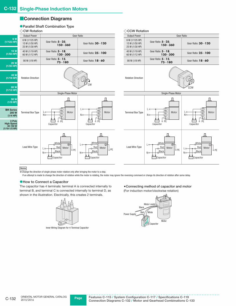
■Connection Diagrams
●Parallel Shaft Combination Type ◇CW RotationOutput Power Gear Ratio
6 W (1/125 HP)15 W (1/50 HP)25 W (1/30 HP)
Gear Ratio: 5∼25, 150∼360 Gear Ratio: 30∼120
40 W (1/19 HP)60 W (1/12 HP)
Gear Ratio: 5∼18, 120∼300 Gear Ratio: 25∼100
90 W (1/8 HP)Gear Ratio: 5∼15, 75∼180 Gear Ratio: 18∼60
Rotation Direction
CW
Single-Phase Motor
Terminal Box Type
Capacitor
LN
PE
U1U2Z2
MotorL
N
CapacitorPE
U1U2Z2
Motor
Lead Wire Type Motor
Capacitor
Black
RedL
N
White
PEMotor
White
RedL
N Black
Capacitor
PE
◇CCW RotationOutput Power Gear Ratio
6 W (1/125 HP)15 W (1/50 HP)25 W (1/30 HP)
Gear Ratio: 5∼25, 150∼360 Gear Ratio: 30∼120
40 W (1/19 HP)60 W (1/12 HP)
Gear Ratio: 5∼18, 120∼300 Gear Ratio: 25∼100
90 W (1/8 HP)Gear Ratio: 5∼15, 75∼180 Gear Ratio: 18∼60
Rotation Direction
CCW
Single-Phase Motor
Terminal Box TypeL
N
CapacitorPE
U1U2Z2
Motor
Capacitor
LN
PE
U1U2Z2
Motor
Lead Wire Type Motor
White
RedL
N Black
Capacitor
PE
Capacitor
Black
RedL
N
White
MotorPE
Note ●Change the direction of single-phase motor rotation only after bringing the motor to a stop.If an attempt is made to change the direction of rotation while the motor is rotating, the motor may ignore the reversing command or change its direction of rotation after some delay.
●How to Connect a CapacitorThe capacitor has 4 terminals: terminal A is connected internally to terminal B, and terminal C is connected internally to terminal D, as shown in the illustration. Electrically, this creates 2 terminals.
A BC D
Inner Wiring Diagram for 4-Terminal Capacitor
●Connecting method of capacitor and motor(For induction motor/clockwise rotation)
MotorCapacitor
WhiteRedPower Supply
Motor LeadsBlack

C-133
Standard AC Motors C-133
Constant
Speed
Motors
Overview,
Product
Series
Three-Phase Induction Motors
Single-PhaseInduction Motors
Reversible Motors
Electromagnetic Brake Motors
Clutch & Brake Motors
Low-Speed Synchronous Motors
Torque
Motors
Watertight,
Dust-Resistant
Motors
Right-Angle
Gearheads
Linear
Heads
Brake Pack
Accessories
Installation
CAD DataManuals
www.orientalmotor.com Technical Support
TEL: (800) 468-3982E-mail: [email protected]
■List of Motor and Gearhead Combinations
●Terminal Box Type
Type Product Name Motor Product NameGearhead
Product Name
Terminal Box Type
4IK25UAT2-□A 4IK25GV-UAT24GV□A
4IK25UCT2-□A 4IK25GV-UCT25IK40UAT2-□A 5IK40GV-UAT2
5GV□A5IK40UCT2-□A 5IK40GV-UCT25IK60UAT2-□A 5IK60GVH-UAT2
5GVH□A5IK60UCT2-□A 5IK60GVH-UCT25IK90UAT2-□A 5IK90GVR-UAT2
5GVR□A5IK90UCT2-□A 5IK90GVR-UCT2
●Lead Wire Type
Type Product Name Motor Product NameGearhead
Product Name
Lead Wire Type
2IK6UA-□A 2IK6GV-UA2GV□A
2IK6UC-□A 2IK6GV-UC3IK15UA-□A 3IK15GV-UA
3GV□A3IK15UC-□A 3IK15GV-UC4IK25UA-□A 4IK25GV-UA
4GV□A4IK25UC-□A 4IK25GV-UC5IK40UA-□A 5IK40GV-UA
5GV□A5IK40UC-□A 5IK40GV-UC5IK60UA-□A 5IK60GVH-UA
5GVH□A5IK60UC-□A 5IK60GVH-UC5IK90UA-□A 5IK90GVR-UA
5GVR□A5IK90UC-□A 5IK90GVR-UC
●A number indicating the gear ratio is entered where the box □ is located within the product name.

C-134
C-134 Single-Phase Induction Motors
ORIENTAL MOTOR GENERAL CATALOG 2015/2016
Page Features C-114 / Specifications C-119 / Connection Diagrams C-140
Motor and Gearhead Combinations C-141
6 W
(1/125 HP)
15 W
(1/50 HP)
25 W
(1/30 HP)
40 W
(1/19 HP)
60 W
(1/12 HP)
90 W
(1/8 HP)
BH Series
200 W
(1/4 HP)
2-Pole High-Speed
40-150 W (1/19-1/5 HP)
High Power Induction Motors BH Series
200 W (1/4 HP)Frame Size: □104 mm (□4.09 in.)
■Features
●High Power 200 W (1/4 HP)Smallest frame size among 200 W (1/4 HP) motors
●Hypoid Gear Right-Angle GearheadsRight-angle gearheads employ hypoid gears. Hollow shafts and solid shafts are available to enable space-saving.
●Tapped Hole at the Shaft EndThe gearhead shafts feature a tapped hole for convenient connection with loads.
●"Combination Type" for Easy InstallationThe combination type comes with the motor and gearhead pre-assembled. This enables easy installation in equipment.
■Specifications – Continuous Rating
Product NameCombination Type
( ) : Round Shaft Type
OutputPower
Voltage Frequency Current Starting Torque Rated Torque Rated Speed Capacitor Overheat Protection
DeviceWHP VAC Hz A
N·moz-in
N·moz-in r/min μFTerminal Box Type Cable Type
BHI62FT-□RHBHI62FT-□RABHI62FT-□(BHI62FT-A)
BHI62F-□RHBHI62F-□RABHI62F-□(BHI62F-A)
2001/4
Single-Phase 11060 3
0.88124 1.27
1801500 40 TP
Single-Phase 1150.98139
BHI62ET-□RHBHI62ET-□RABHI62ET-□(BHI62ET-A)
BHI62E-□RHBHI62E-□RABHI62E-□(BHI62E-A)
2001/4
Single-Phase 22050
1.50.98139
1.52210
1250
10 TP60
1.27180
1500
Single-Phase 23050
1.52210
1250
601.27180
1500
●A number indicating the gear ratio is entered where the box □ is located within the product name. The values for each specification applies to the motor only. ●For detailed information about regulations and standards, please see the Oriental Motor website.
TP: Contains a built-in thermal protector (automatic return type). If a motor overheats for any reason, the thermal protector is activated and the motor is stopped. When the motor temperature drops, the thermal protector closes and the motor restarts. Be sure to turn the motor power off before inspecting.
■Product Line
Motor and gearhead are delivered pre-assembled.The combination of motors and gearheads can be changed and they are also available separately.In addition, the gearhead can be removed and the assembly position can be changed in 90° increments.
Combination Type
●Combination Type ◇Right-Angle Shaft
Type Voltage Product Name Gear Ratio List Price
Hollow ShaftTerminal Box
Single-Phase 110/115 VAC BHI62FT-□RH5, 6, 7.5, 9, 12.5, 15, 18, 25, 30, 36 $426.0050, 60, 75, 90, 100, 120, 150, 180 $446.00
Single-Phase 220/230 VAC BHI62ET-□RH5, 6, 7.5, 9, 12.5, 15, 18, 25, 30, 36 $433.0050, 60, 75, 90, 100, 120, 150, 180 $453.00
Hollow ShaftCable
Single-Phase 110/115 VAC BHI62F-□RH5, 6, 7.5, 9, 12.5, 15, 18, 25, 30, 36 $396.0050, 60, 75, 90, 100, 120, 150, 180 $416.00
Single-Phase 220/230 VAC BHI62E-□RH5, 6, 7.5, 9, 12.5, 15, 18, 25, 30, 36 $403.0050, 60, 75, 90, 100, 120, 150, 180 $423.00
Solid ShaftTerminal Box
Single-Phase 110/115 VAC BHI62FT-□RA5, 6, 7.5, 9, 12.5, 15, 18, 25, 30, 36 $420.0050, 60, 75, 90, 100, 120, 150, 180 $440.00
Single-Phase 220/230 VAC BHI62ET-□RA5, 6, 7.5, 9, 12.5, 15, 18, 25, 30, 36 $427.0050, 60, 75, 90, 100, 120, 150, 180 $447.00
Solid ShaftCable
Single-Phase 110/115 VAC BHI62F-□RA5, 6, 7.5, 9, 12.5, 15, 18, 25, 30, 36 $390.0050, 60, 75, 90, 100, 120, 150, 180 $410.00
Single-Phase 220/230 VAC BHI62E-□RA5, 6, 7.5, 9, 12.5, 15, 18, 25, 30, 36 $397.0050, 60, 75, 90, 100, 120, 150, 180 $417.00
●A number indicating the gear ratio is entered where the box □ is located within the product name.
Cable TypeRight-Angle Hollow Shaft
Terminal Box TypeParallel Shaft
Motor, Gearhead, Capacitor, Capacitor Cap, Parallel Key, Operating Manual
The following items are included with each product.

C-135
Standard AC Motors C-135
Constant
Speed
Motors
Overview,
Product
Series
Three-Phase Induction Motors
Single-PhaseInduction Motors
Reversible Motors
Electromagnetic Brake Motors
Clutch & Brake Motors
Low-Speed Synchronous Motors
Torque
Motors
Watertight,
Dust-Resistant
Motors
Right-Angle
Gearheads
Linear
Heads
Brake Pack
Accessories
Installation
CAD DataManuals
www.orientalmotor.com Technical Support
TEL: (800) 468-3982E-mail: [email protected]
◇Parallel ShaftType Voltage Product Name Gear Ratio List Price
Parallel ShaftTerminal Box
Single-Phase 110/115 VAC BHI62FT-□3, 3.6, 5, 6, 7.5, 9 $364.00
12.5, 15, 18, 25, 30, 36 $374.0050, 60, 75, 90, 100, 120, 150, 180 $383.00
Single-Phase 220/230 VAC BHI62ET-□3, 3.6, 5, 6, 7.5, 9 $371.00
12.5, 15, 18, 25, 30, 36 $381.0050, 60, 75, 90, 100, 120, 150, 180 $391.00
Parallel ShaftCable
Single-Phase 110/115 VAC BHI62F-□3, 3.6, 5, 6, 7.5, 9 $334.00
12.5, 15, 18, 25, 30, 36 $344.0050, 60, 75, 90, 100, 120, 150, 180 $354.00
Single-Phase 220/230 VAC BHI62E-□3, 3.6, 5, 6, 7.5, 9 $342.00
12.5, 15, 18, 25, 30, 36 $351.0050, 60, 75, 90, 100, 120, 150, 180 $361.00
●A number indicating the gear ratio is entered where the box □ is located within the product name.
Motor, Gearhead, Capacitor, Capacitor Cap, Installation Screws, Parallel Key, Operating ManualThe following items are included with each product.
●Round Shaft TypeType Voltage Product Name List Price
Terminal BoxSingle-Phase 110/115 VAC BHI62FT-A $214.00Single-Phase 220/230 VAC BHI62ET-A $221.00
CableSingle-Phase 110/115 VAC BHI62F-A $184.00Single-Phase 220/230 VAC BHI62E-A $191.00
Motor, Capacitor, Capacitor Cap, Operating ManualThe following items are included with each product.
■Gearmotor – Torque Table for Combination Type ● Enter the code that represents the terminal box type “T” in the box ■□ within the product name. ● A number indicating the gear ratio is entered where the box □ is located within the product name. ● The speed is calculated by dividing the motor's synchronous speed (50 Hz: 1500 r/min, 60 Hz: 1800 r/min) by the gear ratio. The actual speed is 2∼20% less than the displayed value, depending on the load. ● Decimal gearheads are not available for the BH series.
●Right-Angle Shaft 50 Hz Unit: Upper values: N·m/Lower values: lb-in
Product NameSpeedr/min
300 250 200 167 120 100 83 60 50 42 30 25 20 17 15 12.5 10 8.3
Gear Ratio 5 6 7.5 9 12.5 15 18 25 30 36 50 60 75 90 100 120 150 180
BHI62E■□-□RH, BHI62E■□-□RA 5.548
6.759
8.373
10.088
13.9123
16.6146
20.0177
27.7240
33.3290
36.0310
40.0350
43.0380
47.0410
51.5450
54.5480
60530
60530
60530
●Right-Angle Shaft 60 Hz Unit: Upper values: N·m/Lower values: lb-in
Product NameSpeedr/min
360 300 240 200 144 120 100 72 60 50 36 30 24 20 18 15 12 10
Gear Ratio 5 6 7.5 9 12.5 15 18 25 30 36 50 60 75 90 100 120 150 180BHI62F■□-□RH, BHI62F■□-□RABHI62E■□-□RH, BHI62E■□-□RA
4.640
5.649
7.061
8.373
11.6102
13.9123
16.7147
23.2200
27.8240
33.4290
40.0350
43.0380
47.0410
51.5450
54.5480
60530
60530
60530
●Parallel Shaft 50 Hz Unit: Upper values: N·m/Lower values: lb-in
Product NameSpeedr/min
500 417 300 250 200 167 120 100 83 60 50 42 30 25 20 17 15 12.5 10 8.3
Gear Ratio 3 3.6 5 6 7.5 9 12.5 15 18 25 30 36 50 60 75 90 100 120 150 180
BHI62E■□-□ 4.136
4.943
6.860
8.272
10.391
12.3108
16.3144
19.6173
23.5200
32.7280
39.2340
40350
40350
40350
40350
40350
40350
40350
40350
40350
●Parallel Shaft 60 Hz Unit: Upper values: N·m/Lower values: lb-in
Product NameSpeedr/min
600 500 360 300 240 200 144 120 100 72 60 50 36 30 24 20 18 15 12 10
Gear Ratio 3 3.6 5 6 7.5 9 12.5 15 18 25 30 36 50 60 75 90 100 120 150 180
BHI62F■□-□, BHI62E■□-□ 3.430
4.136
5.750
6.961
8.676
10.391
13.7121
16.4145
19.7174
27.3240
32.8290
39.3340
40350
40350
40350
40350
40350
40350
40350
40350
■Permissible Radial Load and Permissible AxialCombination Type ➜ Page C-17Round Shaft Type ➜ Page C-17
■Permissible Inertia J of Gearhead➜ Page C-18

C-136
C-136 Single-Phase Induction Motors
ORIENTAL MOTOR GENERAL CATALOG 2015/2016
Page Features C-114 / Specifications C-119 / Connection Diagrams C-140
Motor and Gearhead Combinations C-141
6 W
(1/125 HP)
15 W
(1/50 HP)
25 W
(1/30 HP)
40 W
(1/19 HP)
60 W
(1/12 HP)
90 W
(1/8 HP)
BH Series
200 W
(1/4 HP)
2-Pole High-Speed
40-150 W (1/19-1/5 HP)
■Dimensions Unit = mm (in.)
● Installation screws are included with the combination type, parallel shaft. Dimensions for installation screws ➜ Page C-215
◇Combination Type: Right-Angle, Hollow Shaft (Terminal Box Type)BHI62FT-□RH, BHI62ET-□RHMass: 10.0 kg (22 lb.)Motor: BHI62FT-G2, BHI62ET-G2Gearhead: BH6G2-□RH
A301
025−0.2 0
7−0.03608−
0.03
6
A
A
160 (6.30)
ϕ40 (ϕ1.57)
99 ( 3
.90)
118
( 4.6
5)
A−A
154 (6.06)□
103
( □4.
06)
102 (4.02)
16 ( 0
.63)
4 ( 0.1
6)
ϕ58−0.046
(ϕ2.2835−0.0018)0
0
15 (0.59)1.5 (0.06)
30 (1.18)109.3 (4.30)
30 (1.18)15 (0.59)1.5 (0.06)
4.8(0.19)
Flange Mounting Surface
Groove for Retaining Ring ϕ26.2 0 (ϕ1.03 0 )+0.008+0.21
9 (0.35)75 (2.95)28 (1.10) max.
8 0 +0.04
(0.31 0 )+0.0016
25 0 (0.9843 0 )+0.0013+0.033
ϕ120±0.5
(ϕ4.72±0.02)
104
( 4.0
9)
28.3
( 1.1
1)
4×ϕ8.5 (ϕ0.335) Thru 66(2.60)
62 (2.44)
43 ( 1
.69)
(0.984−0.008)0 (0.2756−0.0014)0
( 0.3
150−
0.00
14)
0
104 (4.09)
25 ( 0
.98)
●Use cable with a diameter of ϕ6∼ϕ12 mm (ϕ0.24∼ϕ0.47 in.). ●Details of terminal box ➜ Page C-214
◇Combination Type: Right-Angle, Solid Shaft (Terminal Box Type)BHI62FT-□RA, BHI62ET-□RAMass: 10.0 kg (22 lb.)Motor: BHI62FT-G2, BHI62ET-G2Gearhead: BH6G2-□RA
A302
102 (4.02)
24.5 (0.96)
16 ( 0
.63) 99
( 3.9
0)11
8 ( 4
.65)
48 ( 1
.89)
4 ( 0
.16)
154 (6.06)160 (6.30)
75 (2.95) 9 (0.35)
104
( 4.0
9)
62 (2.44)
104 (4.09) 66 (2.60)
32 ( 1
.26)
43 ( 1
.69)
ϕ120±0.5
(ϕ4.72±0.02)
□10
3 ( □
4.06
)
28 (1.10) max.
40±
0.5
( 1.5
7±0.
02)
ϕ22−0.021 (ϕ0.8661−0.0008)0
ϕ58−0.046 (ϕ2.2835−0.0018)0
0
0
4×ϕ8.5 (ϕ0.335) Thru
M6×12 (0.47) Deep
32±0.2
(1.260±0.008)
018.5−0.1
(0.728−0.004)0
6−0.03
(0.2362−0.0012) 00
06−
0.03
( 0.23
62−
0.00
12)
0
25 ( 0
.98)
●Use cable with a diameter of ϕ6∼ϕ12 mm (ϕ0.24∼ϕ0.47 in.). ●Details of terminal box ➜ Page C-214
●A number indicating the gear ratio is entered where the box □ is located within the product name.
●At the time of shipment, a key is inserted on the gearhead’s shaft.
◇Key (Included)
◇Key and Key Slot (Included)

C-137
Standard AC Motors C-137
Constant
Speed
Motors
Overview,
Product
Series
Three-Phase Induction Motors
Single-PhaseInduction Motors
Reversible Motors
Electromagnetic Brake Motors
Clutch & Brake Motors
Low-Speed Synchronous Motors
Torque
Motors
Watertight,
Dust-Resistant
Motors
Right-Angle
Gearheads
Linear
Heads
Brake Pack
Accessories
Installation
CAD DataManuals
www.orientalmotor.com Technical Support
TEL: (800) 468-3982E-mail: [email protected]
◇Combination Type: Right-Angle, Hollow Shaft (Cable Type)BHI62F-□RH, BHI62E-□RHMass: 10.0 kg (22 lb.)Motor: BHI62F-G2, BHI62E-G2Gearhead: BH6G2-□RH
A299
A
A
Motor Cable ϕ7.8 (ϕ0.31), 500 mm (20 in.) LengthUL Style 3271, AWG20
4×ϕ8.5 (ϕ0.335) Thru
Protective Earth Terminal M4
0
08−
0.03
6
25−0.2 07−0.036
A−A
15 (0.59)1.5 (0.06)
30 (1.18)109.3 (4.30)
30 (1.18)15 (0.59)1.5 (0.06)
Groove for Retaining Ring ϕ26.2 0 (ϕ1.03 0 )+0.008+0.214.8(0.19)
Flange Mounting Surface
(0.984−0.008)0
( 0.3
150−
0.00
14)
0
(0.2756−0.0014)0□
103
( □4.
06)
160 (6.30)
20.5
( 0.8
1)
58 (25.4)154 (6.06)
99 ( 3
.90)
16 ( 0
.63)
118
( 4.6
5)
102 (4.02)
ϕ40 (ϕ1.57)4 (0.16)
32.5(1.28)
66 (2.60)104 (4.09)
14
( 0.5
5) 27 (1.06)8 0
+0.04
(0.31 0 ) ϕ120±0.5
(ϕ4.72±0.02)+0.0016
25 0 (0.9843 0 )+0.0013+0.033
104
( 4.0
9)
28.3
( 1.1
1)
0ϕ58−0.046
(ϕ2.2835−0.0018)0
◇Combination Type: Right-Angle, Solid Shaft (Cable Type)BHI62F-□RA, BHI62E-□RAMass: 10.0 kg (22 lb.)Motor: BHI62F-G2, BHI62E-G2Gearhead: BH6G2-□RA
A300
58 (25.4)
20.5
( 0.8
1)
27(1.06)14
( 0.5
5)
ϕ120±0.5
(ϕ4.72±0.02)
104
( 4.0
9)
66 (2.60)104 (4.09)
Protective Earth Terminal M4
Motor Cable ϕ7.8(ϕ0.31), 500 mm (20 in.) LengthUL Style 3271, AWG20
4×ϕ8.5 (ϕ0.335) Thru
M6×12 (0.47) Deep
32±0.2
(1.260±0.008)
018.5−0.1
(0.728−0.004)0
6−0.03
(0.2362−0.0012) 00
06−
0.03
( 0.23
62−
0.00
12)
0
99 ( 3
.90)
118
( 4.6
5)
16 ( 0
.63)
154 (6.06)160 (6.30)
□10
3 ( □
4.06
)
24.5 (0.96)
102 (4.02)ϕ22−0.021 (ϕ0.8661−0.0008)00
ϕ58−0.046 (ϕ2.2835−0.0018)00
48 ( 1
.89)
32 ( 1
.26)
40±
0.5
( 1.5
7±0.
02)
4 ( 0
.16)
32.5(1.28)
●A number indicating the gear ratio is entered where the box □ is located within the product name.
●At the time of shipment, a key is inserted on the gearhead’s shaft.
◇Key (Included)
◇Key and Key Slot (Included)

C-138
C-138 Single-Phase Induction Motors
ORIENTAL MOTOR GENERAL CATALOG 2015/2016
Page Features C-114 / Specifications C-119 / Connection Diagrams C-140
Motor and Gearhead Combinations C-141
6 W
(1/125 HP)
15 W
(1/50 HP)
25 W
(1/30 HP)
40 W
(1/19 HP)
60 W
(1/12 HP)
90 W
(1/8 HP)
BH Series
200 W
(1/4 HP)
2-Pole High-Speed
40-150 W (1/19-1/5 HP)
◇Combination Type: Parallel Shaft (Terminal Box Type)BHI62FT-□, BHI62ET-□Mass: 8.0 kg (18 lb.)Motor: BHI62FT-G2, BHI62ET-G2Gearhead: BH6G2-□
A304
20.5
( 0.8
1)25 (0.98)
20 ( 0
.79)
104
( 4.0
9)43
( 1.6
9)
62 (2.44)
104 (4.09)10.5 (0.41) 5 (0.20)
72 (2.83) 42 (1.65)
75 (2.95) 9 (0.35)
160 (6.30)
25 ( 0
.98)
ϕ120±0.5
(ϕ4.72±0.02)
ϕ18
−0.
018
( ϕ0.
7087
−0.
0007
)0
33.5±0.5 (1.32±0.02)
ϕ42
(ϕ1.
65)
ϕ 20 (
ϕ 0.7
9)
28 (1.10) max.
□10
3 ( □
4.06
)
0
M6×12 (0.47) Deep
4×ϕ8.5 (ϕ0.335) Thru
●Use cable with a diameter of ϕ6∼ϕ12 mm (ϕ0.24∼ϕ0.47 in.). ●Details of terminal box ➜ Page C-214
◇Combination Type: Parallel Shaft (Cable Type)BHI62F-□, BHI62E-□Mass: 8.0 kg (18 lb.)Motor: BHI62F-G2, BHI62E-G2Gearhead: BH6G2-□
A303
5 ( 0
.20)
max
.
ϕ20
(ϕ0.
79)
58 (2.28)
20.5
( 0.8
1)
M6×12 (0.47) Deep
4×ϕ8.5 (ϕ0.335) Thru
Motor Cable ϕ7.8 (ϕ0.31), 500 mm (20 in.) LengthUL Style 3271, AWG20
Protective Earth Terminal M4
Protective Earth Terminal M4
ϕ120±0.5
(ϕ4.72±0.02)
104 (4.09)
□10
3 ( □
4.06
)
25(0.98)
20 ( 0
.79)
ϕ42
(ϕ1.
65)
14 ( 0
.55)
10.5 (0.41)5 (0.20)
160 (6.30) 72 (2.83) 42 (1.65)
32.5(1.28) 27
(1.06)
20.5
( 0.8
1)
33.5±0.5
(1.32±0.02)ϕ
18−
0.01
8 (ϕ
0.70
87−
0.00
07)
00
104
( 4.0
9)
06−0.03
(0.2362−0.0012) 0
06−
0.03
( 0.23
62−
0.00
12)
0
( 0.5
71−
0.00
4)0
25±0.2
(0.984±0.008)
014
.5−
0.1
◇Key and Key Slot (Included, common as BHI62)
●At the time of shipment, a key is inserted on the gearhead’s shaft.
●A number indicating the gear ratio is entered where the box □ is located within the product name.

C-139
Standard AC Motors C-139
Constant
Speed
Motors
Overview,
Product
Series
Three-Phase Induction Motors
Single-PhaseInduction Motors
Reversible Motors
Electromagnetic Brake Motors
Clutch & Brake Motors
Low-Speed Synchronous Motors
Torque
Motors
Watertight,
Dust-Resistant
Motors
Right-Angle
Gearheads
Linear
Heads
Brake Pack
Accessories
Installation
CAD DataManuals
www.orientalmotor.com Technical Support
TEL: (800) 468-3982E-mail: [email protected]
◇Round Shaft Type (Terminal Box Type)BHI62FT-A, BHI62ET-AMass: 5.0 kg (11 lb.)
A308
□10
3 ( □
4.06
)
10.5 (0.41)160 (6.30)
ϕ120±0.5
(ϕ4.72±0.02)30
(1.18)
43 ( 1
.69)
□10
4 ( □
4.09
)
37 (1.46)2 (0.08)
13 ( 0
.51)
62(2.44)9 (0.35)75 (2.95)28 (1.10) max.
ϕ14−0.018
(ϕ0.5512−0.0007)0
0
4×ϕ8.5 (ϕ0.335) Thru
ϕ94
−0.
035
( ϕ3.
7008
−0.
0014
)0
0
25 ( 0
.98)
●Use cable with a diameter of ϕ6∼ϕ12 mm (ϕ0.24∼ϕ0.47 in.). ●Details of terminal box ➜ Page C-214
◇Round Shaft Type (Cable Type)BHI62F-A, BHI62E-AMass: 5.0 kg (11 lb.)
A307
5 ( 0
.20)
max
.
58 (2.28)
20.5
( 0.8
1)
Protective Earth Terminal M4
Protective Earth Terminal M4
4×ϕ8.5 (ϕ0.335) Thru
Motor Cable ϕ7.8, (ϕ0.31), 500 mm (20 in.) LengthUL Style 3271, AWG20
ϕ120±0.5
(ϕ4.72±0.02)
□10
3 ( □
4.06
)
□10
4 ( □
4.09
)37 (1.46)160 (6.30)2 (0.08)
30(1.18) 13
( 0.5
1)
10.5 (0.41)
ϕ14
−0.
018 (
ϕ0.
5512
−0.
0007
)0
0
ϕ94
−0.
035 ( ϕ
3.70
08−
0.00
14)
00
32.5(1.28)
14 ( 0
.55)
27(1.06)
◇Capacitor (Included with single-phase motors)
6 (0.24)
A
CB
7( 0
.28)20
(0.79)
10( 0
.39)
AMP#187
ϕ4.3(ϕ0.169)
4( 0
.16)
B+15
( 0.5
9)
R10(R0.39)
◇Capacitor Dimensions Unit: mm (in.)
Product Name Capacitor Product Name
A B CMassg (oz.)
CapacitorCapTerminal Box Type Cable Type
BHI62FT-□RHBHI62FT-□RABHI62FT-□BHI62FT-A
BHI62F-□RHBHI62F-□RABHI62F-□BHI62F-A
CH400CFAUL2 58(2.28)
41(1.61)
58(2.28)
175(6.2)
IncludedBHI62ET-□RHBHI62ET-□RABHI62ET-□BHI62ET-A
BHI62E-□RHBHI62E-□RABHI62E-□BHI62E-A
CH100BFAUL 58(2.28)
35(1.38)
50(1.97)
132(4.7)
●A number indicating the gear ratio is entered where the box □ is located within the product name.

C-140
C-140 Single-Phase Induction Motors
ORIENTAL MOTOR GENERAL CATALOG 2015/2016
Page Features C-114 / Specifications C-119 / Connection Diagrams C-140
Motor and Gearhead Combinations C-141
6 W
(1/125 HP)
15 W
(1/50 HP)
25 W
(1/30 HP)
40 W
(1/19 HP)
60 W
(1/12 HP)
90 W
(1/8 HP)
BH Series
200 W
(1/4 HP)
2-Pole High-Speed
40-150 W (1/19-1/5 HP)
●Combination Type Parallel Shaft/Round Shaft Type ◇CW Rotation
Product Name
Type and Gear Ratio
BHI62Gear Ratio: 3∼9, 50∼180Round shaft type
Gear Ratio: 12.5∼36
Rotation Direction
CW
Single-Phase Motor
Terminal Box Type
Capacitor
LN
PE
U1U2Z2
MotorL
N
CapacitorPE
U1U2Z2
Motor
Cable Type Motor
Capacitor
Black
RedL
N
White
PEMotor
White
RedL
N Black
Capacitor
PE
◇CCW Rotation
Product Name
Type and Gear Ratio
BHI62Gear Ratio: 3∼9, 50∼180Round shaft type
Gear Ratio: 12.5∼36
Rotation Direction
CCW
Single-Phase Motor
Terminal Box Type
L
N
CapacitorPE
U1U2Z2
Motor
Capacitor
LN
PE
U1U2Z2
Motor
Cable Type Motor
White
RedL
N Black
Capacitor
PEMotor
Capacitor
Black
RedL
N
White
PE
Note ●Change the direction of single-phase motor rotation only after bringing the motor to a stop.If an attempt is made to change the direction of rotation while the motor is rotating, the motor may ignore the reversing command or change its direction of rotation after some delay. ●Connect a CR circuit to protect the contact of switches. Connection of CR circuit, contact capacity ➜ Page C-213 ●For added safety, provide a breaker or fuse on the power-supply input.
●How to Connect a CapacitorThe capacitor has 4 terminals: terminal A is connected internally to terminal B, and terminal C is connected internally to terminal D, as shown in the illustration.Electrically, this creates 2 terminals.
A BC D
Inner Wiring Diagram for 4-Terminal Capacitor
■Connection Diagrams
● The rotation direction of the motor is indicated when viewed from the output shaft side of the motor. CW is used to indicate clockwise rotation and CCW is used for counterclockwise rotation.
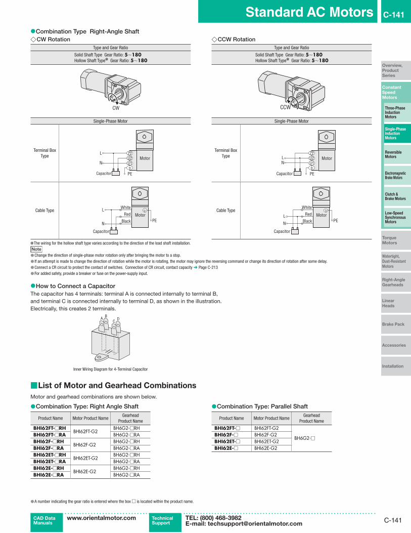
C-141
Standard AC Motors C-141
Constant
Speed
Motors
Overview,
Product
Series
Three-Phase Induction Motors
Single-PhaseInduction Motors
Reversible Motors
Electromagnetic Brake Motors
Clutch & Brake Motors
Low-Speed Synchronous Motors
Torque
Motors
Watertight,
Dust-Resistant
Motors
Right-Angle
Gearheads
Linear
Heads
Brake Pack
Accessories
Installation
CAD DataManuals
www.orientalmotor.com Technical Support
TEL: (800) 468-3982E-mail: [email protected]
●Combination Type Right-Angle Shaft ◇CW Rotation
Type and Gear Ratio
Solid Shaft Type Gear Ratio: 5∼180Hollow Shaft Type✽ Gear Ratio: 5∼180
CW
Single-Phase Motor
Terminal Box Type
L
N
Capacitor PE
U1U2Z2
Motor
Cable TypeWhite
RedL
N Black
Capacitor
MotorPE
◇CCW RotationType and Gear Ratio
Solid Shaft Type Gear Ratio: 5∼180Hollow Shaft Type✽ Gear Ratio: 5∼180
CCW
Single-Phase Motor
Terminal Box Type
Capacitor
LN
PE
U1U2Z2
Motor
Cable Type
Capacitor
Black
RedL
N
White
MotorPE
✽The wiring for the hollow shaft type varies according to the direction of the load shaft installation.Note
●Change the direction of single-phase motor rotation only after bringing the motor to a stop. ● If an attempt is made to change the direction of rotation while the motor is rotating, the motor may ignore the reversing command or change its direction of rotation after some delay. ●Connect a CR circuit to protect the contact of switches. Connection of CR circuit, contact capacity ➜ Page C-213 ●For added safety, provide a breaker or fuse on the power-supply input.
●How to Connect a CapacitorThe capacitor has 4 terminals: terminal A is connected internally to terminal B, and terminal C is connected internally to terminal D, as shown in the illustration.Electrically, this creates 2 terminals.
A BC D
Inner Wiring Diagram for 4-Terminal Capacitor
■List of Motor and Gearhead Combinations
Motor and gearhead combinations are shown below.
●Combination Type: Right Angle Shaft
Product Name Motor Product NameGearhead
Product Name
BHI62FT-□RHBHI62FT-G2
BH6G2-□RHBHI62FT-□RA BH6G2-□RABHI62F-□RH
BHI62F-G2BH6G2-□RH
BHI62F-□RA BH6G2-□RABHI62ET-□RH
BHI62ET-G2BH6G2-□RH
BHI62ET-□RA BH6G2-□RABHI62E-□RH
BHI62E-G2BH6G2-□RH
BHI62E-□RA BH6G2-□RA
●Combination Type: Parallel Shaft
Product Name Motor Product NameGearhead
Product Name
BHI62FT-□ BHI62FT-G2
BH6G2-□BHI62F-□ BHI62F-G2BHI62ET-□ BHI62ET-G2BHI62E-□ BHI62E-G2
●A number indicating the gear ratio is entered where the box □ is located within the product name.

C-142
C-142 Single-Phase Induction Motors
ORIENTAL MOTOR GENERAL CATALOG 2015/2016
Page Features C-114 / Specifications C-119 / Connection Diagrams C-145
6 W
(1/125 HP)
15 W
(1/50 HP)
25 W
(1/30 HP)
40 W
(1/19 HP)
60 W
(1/12 HP)
90 W
(1/8 HP)
BH Series
200 W
(1/4 HP)
2-Pole High-Speed
40-150 W (1/19-1/5 HP)
Induction Motors 2-Pole, High-Speed Type
40 W (1/19 HP), 60 W (1/12 HP), 90 W (1/8 HP), 150 W (1/5 HP)Frame Size: □80 mm (□3.15 in.), □90 mm (□3.54 in.)
■Specifications – Continuous Rating
Product Name Output Power Voltage Frequency Current Starting Torque Rated TorqueRatedSpeed
Capacitor Overheat Protection
DeviceRound Shaft Type W HP VAC Hz A mN·m oz-in mN·m oz-in r/min μF
4IK40A-BW2U 40 1/19Single-Phase 110
600.68
90 12.7 135 19.1 2900 7.5 TPSingle-Phase 115 0.66
4IK40A-DW3E36 1/20 Single-Phase 220
50 0.30
90 12.7
145 20 2400
1.8 TP60 0.31 120 17.0 2900
40 1/19 Single-Phase 23050 0.33 160 22 240060 0.32 135 19.1 2900
4IK60A-BW2U 60 1/12Single-Phase 110
600.98
160 22 190 26 3000 10 TPSingle-Phase 115 0.97
4IK60A-DW3E55 1/14 Single-Phase 220
50 0.44
160 22
210 29 2500
2.5 TP60 0.51 180 25 3000
60 1/12 Single-Phase 23050 0.47 230 32 250060 0.52 190 26 3000
5IK60A-BW2U 60 1/12Single-Phase 110
600.94
140 19.8 185 26 3200 14 TPSingle-Phase 115 0.93
5IK60A-DW3E 60 1/12Single-Phase 220
500.46 120 17.0
220 31 2650
3.0 TP60 185 26 3200
Single-Phase 23050
0.45 140 19.8220 31 2650
60 185 26 3200
5IK90A-BW2U 90 1/8Single-Phase 110
601.61
240 34 280 39 3200 25 TPSingle-Phase 115 1.57
5IK90A-DW3E 90 1/8Single-Phase 220
50 0.70
240 34
330 46 2650
6.0 TP60 0.84 280 39 3200
Single-Phase 23050 0.69 330 46 265060 0.84 280 39 3200
5IK150A-BW2U 150 1/5Single-Phase 110
602.12
380 53 460 65 3200 30 TPSingle-Phase 115 2.09
5IK150A-DW3E140 1/5 Single-Phase 220
50 0.98
380 53
510 72 2650
8.0 TP60 1.07 420 59 3200
150 1/5 Single-Phase 23050 1.04 560 79 265060 1.13 460 65 3200
TP: Contains a built-in thermal protector (automatic return type). If a motor overheats for any reason, the thermal protector is activated and the motor is stopped.When the motor temperature drops, the thermal protector closes and the motor restarts. Be sure to turn the motor power off before inspecting.

C-143
Standard AC Motors C-143
Constant
Speed
Motors
Overview,
Product
Series
Three-Phase Induction Motors
Single-PhaseInduction Motors
Reversible Motors
Electromagnetic Brake Motors
Clutch & Brake Motors
Low-Speed Synchronous Motors
Torque
Motors
Watertight,
Dust-Resistant
Motors
Right-Angle
Gearheads
Linear
Heads
Brake Pack
Accessories
Installation
CAD DataManuals
www.orientalmotor.com Technical Support
TEL: (800) 468-3982E-mail: [email protected]
■Product Line
●MotorOutput Power Voltage Product Name List Price
Motor, Capacitor, Capacitor Cap, Operating ManualThe following items are included with each product.
40 W(1/19 HP)
Single-Phase 110-115 VAC 4IK40A-BW2U $93.00Single-Phase 220-230 VAC 4IK40A-DW3E $97.00
60 W(1/12 HP)
Single-Phase 110-115 VAC 4IK60A-BW2U $116.00Single-Phase 220-230 VAC 4IK60A-DW3E $122.00Single-Phase 110-115 VAC 5IK60A-BW2U $112.00Single-Phase 220-230 VAC 5IK60A-DW3E $116.00
90 W(1/8 HP)
Single-Phase 110-115 VAC 5IK90A-BW2U $132.00Single-Phase 220-230 VAC 5IK90A-DW3E $138.00
150 W(1/5 HP)
Single-Phase 110-115 VAC 5IK150A-BW2U $166.00Single-Phase 220-230 VAC 5IK150A-DW3E $173.00
■Dimensions Unit = mm (in.)
●40 W (1/19 HP)4IK40A-BW2U, 4IK40A-DW3EMass: 1.5 kg (3.3 lb.)
A450
4×ϕ5.5 (ϕ0.217) Thru
□80
( □3.
15)
7(0.28)
2(0.08)
ϕ79
(ϕ3.
11)
32(1.26)
85 (3.35)
ϕ94±0.5 (ϕ3.70±0.02)
22.5˚
25(0.98)
Motor Leads 300 mm (12 in.) LengthUL Style 3271, AWG20
7 ( 0
.28)
5 (0.20) max.
Protective Earth TerminalM4
ϕ8−0.015
(ϕ0.3150−0.0006)0
0
ϕ73
−0.
030
( ϕ2.
8740
−0.
0012
)0
0
16.5
( 0.6
5)
21.5 (0.85)
Detail Drawing of Protective Earth Terminal
Protective Earth TerminalM4
●60 W (1/12 HP)4IK60A-BW2U, 4IK60A-DW3EMass: 1.8 kg (4.0 lb.)
A513
4×ϕ5.5 (ϕ0.217) Thru
100 (3.94)
22.5˚Motor Leads 300 mm (12 in.) LengthUL Style 3271, AWG20
□82
( □3.
23)
5 (0.20) max.
Protective Earth TerminalM4
7(0.28)
2(0.08)
32(1.26)
25(0.98) ϕ94±0.5 (ϕ3.70±0.02)
□80
( □3.
15)
9 ( 0
.35) ϕ10−0.015
(ϕ0.3937−0.0006)0
0
ϕ73
−0.
030
( ϕ2.
8740
−0.
0012
)0
0
16.5
( 0.6
5)
21.5 (0.85)
Detail Drawing of Protective Earth Terminal
Protective Earth TerminalM4

C-144
C-144 Single-Phase Induction Motors
ORIENTAL MOTOR GENERAL CATALOG 2015/2016
Page Features C-114 / Specifications C-119 / Connection Diagrams C-145
6 W
(1/125 HP)
15 W
(1/50 HP)
25 W
(1/30 HP)
40 W
(1/19 HP)
60 W
(1/12 HP)
90 W
(1/8 HP)
BH Series
200 W
(1/4 HP)
2-Pole High-Speed
40-150 W (1/19-1/5 HP)
5IK60A-BW2U, 5IK60A-DW3EMass: 2.5 kg (5.5 lb.)
A453
ϕ89
(ϕ3.
50)
2(0.08)
7.5(0.30)
37 (1.46)105 (4.13)
30(1.18)
22.5˚
4×ϕ6.5 (ϕ0.256) Thru
ϕ104±0.5 (ϕ4.09±0.02)
Motor Leads 300 mm (12 in.) LengthUL Style 3271, AWG20
Protective Earth TerminalM4
9 ( 0
.35)
□90
( □3.
54)
5 (0.20) max.
ϕ10−0.015
(ϕ0.3937−0.0006)0
0
ϕ83
−0.
035
( ϕ3.
2677
−0.
0014
)0
0
16.5
( 0.6
5)
21.5 (0.85)
Detail Drawing of Protective Earth Terminal
Protective Earth TerminalM4
●90 W (1/8 HP)5IK90A-BW2U, 5IK90A-DW3EMass: 2.7 kg (5.9 lb.)
A456
4×ϕ6.5 (ϕ0.256) Thru
ϕ104±0.5 (ϕ4.09±0.02)
□90
( □3.
54)
22.5˚
□90
( □3.
54) 30
(1.18)
120 (4.72) 37(1.46)7.5
(0.30)2
(0.08)
11( 0
.43)
Motor Leads 300 mm (12 in.) LengthUL Style 3271, AWG20
ϕ12
−0.
018
0
5 (0.20) max.
Protective Earth TerminalM4
ϕ83
−0.
035
0( ϕ
3.26
77−
0.00
14)
0
( ϕ0.
4724
−0.
0007
)0
16.5
( 0.6
5)
21.5 (0.85)
Detail Drawing of Protective Earth Terminal
Protective Earth TerminalM4
●150 W (1/5 HP)5IK150A-BW2U, 5IK150A-DW3EMass: 3.2 kg (7.0 lb.)
A459
4×ϕ6.5 (ϕ0.256) Thru
□90
( □3.
54)
22.5˚
□90
( □3.
54) 30
(1.18)
135 (5.31) 37(1.46)7.5
(0.30)2
(0.08)
11( 0
.43)
Motor Leads 300 mm (12 in.) LengthUL Style 3271, AWG20
5 (0.20) max.
Protective Earth TerminalM4
ϕ12
−0.
018
( ϕ0.
4724
−0.
0007
)0
0
ϕ83
−0.
035
( ϕ3.
2677
−0.
0014
)0
0
ϕ104±0.5 (ϕ4.09±0.02)
16.5
( 0.6
5)
21.5 (0.85)
Detail Drawing of Protective Earth Terminal
Protective Earth TerminalM4
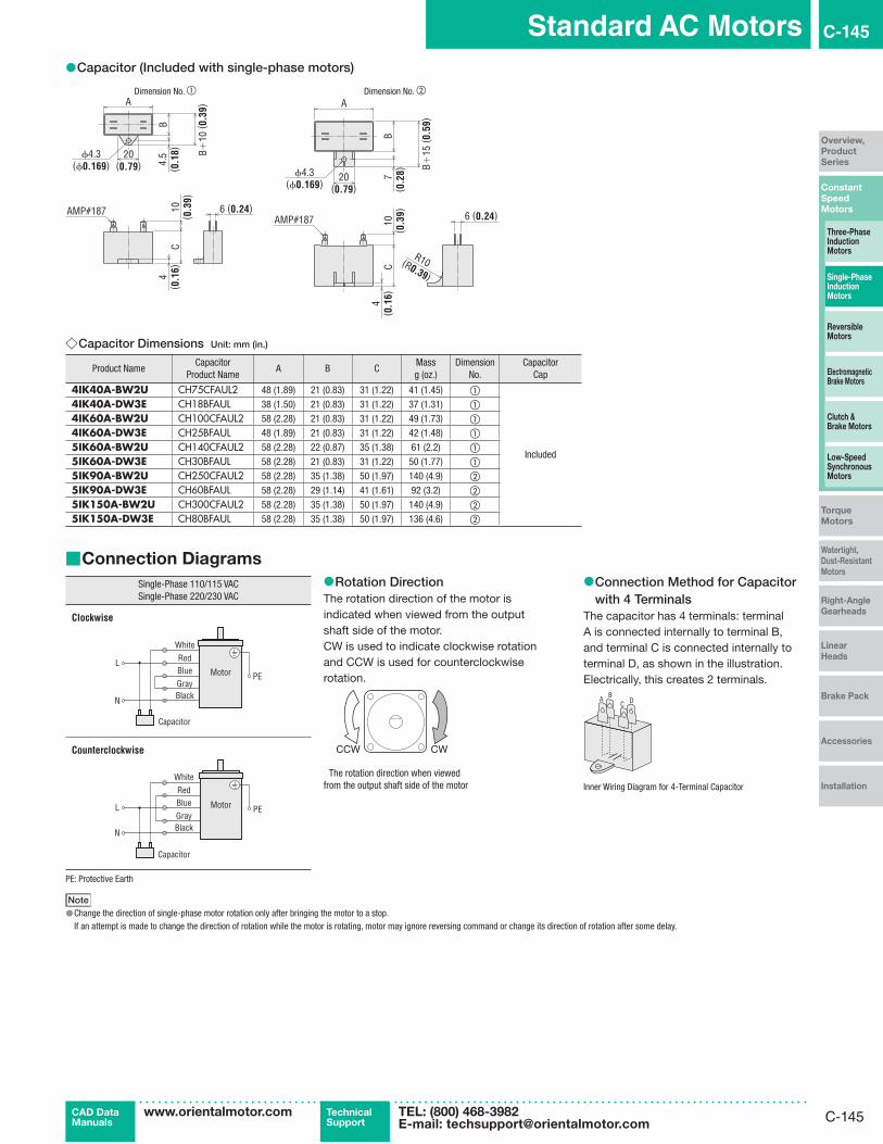
C-145
Standard AC Motors C-145
Constant
Speed
Motors
Overview,
Product
Series
Three-Phase Induction Motors
Single-PhaseInduction Motors
Reversible Motors
Electromagnetic Brake Motors
Clutch & Brake Motors
Low-Speed Synchronous Motors
Torque
Motors
Watertight,
Dust-Resistant
Motors
Right-Angle
Gearheads
Linear
Heads
Brake Pack
Accessories
Installation
CAD DataManuals
www.orientalmotor.com Technical Support
TEL: (800) 468-3982E-mail: [email protected]
●Capacitor (Included with single-phase motors)
Dimension No. ① Dimension No. ②
ϕ4.3(ϕ0.169)
20(0.79)
A
C
B +10
( 0.3
9)
B4.
5( 0
.18)
4( 0
.16)
10( 0
.39)
6 (0.24)AMP#187
6 (0.24)
A
CB
7( 0
.28)20
(0.79)
10( 0
.39)
AMP#187
ϕ4.3(ϕ0.169)
4( 0
.16)
B+15
( 0.5
9)
R10(R0.39)
◇Capacitor Dimensions Unit: mm (in.)
Product NameCapacitor
Product NameA B C
Massg (oz.)
Dimension No.
CapacitorCap
4IK40A-BW2U CH75CFAUL2 48 (1.89) 21 (0.83) 31 (1.22) 41 (1.45) ①
Included
4IK40A-DW3E CH18BFAUL 38 (1.50) 21 (0.83) 31 (1.22) 37 (1.31) ①
4IK60A-BW2U CH100CFAUL2 58 (2.28) 21 (0.83) 31 (1.22) 49 (1.73) ①
4IK60A-DW3E CH25BFAUL 48 (1.89) 21 (0.83) 31 (1.22) 42 (1.48) ①
5IK60A-BW2U CH140CFAUL2 58 (2.28) 22 (0.87) 35 (1.38) 61 (2.2) ①
5IK60A-DW3E CH30BFAUL 58 (2.28) 21 (0.83) 31 (1.22) 50 (1.77) ①
5IK90A-BW2U CH250CFAUL2 58 (2.28) 35 (1.38) 50 (1.97) 140 (4.9) ②
5IK90A-DW3E CH60BFAUL 58 (2.28) 29 (1.14) 41 (1.61) 92 (3.2) ②
5IK150A-BW2U CH300CFAUL2 58 (2.28) 35 (1.38) 50 (1.97) 140 (4.9) ②
5IK150A-DW3E CH80BFAUL 58 (2.28) 35 (1.38) 50 (1.97) 136 (4.6) ②
■Connection Diagrams
Single-Phase 110/115 VACSingle-Phase 220/230 VAC
Clockwise
Black
RedL
N
White
GrayBlue Motor PE
Capacitor
Counterclockwise
Capacitor
Black
Red
L
N
White
GrayBlue Motor PE
PE: Protective Earth
Note ●Change the direction of single-phase motor rotation only after bringing the motor to a stop.If an attempt is made to change the direction of rotation while the motor is rotating, motor may ignore reversing command or change its direction of rotation after some delay.
●Rotation DirectionThe rotation direction of the motor is indicated when viewed from the output shaft side of the motor.CW is used to indicate clockwise rotation and CCW is used for counterclockwise rotation.
CWCCW
The rotation direction when viewed from the output shaft side of the motor
●Connection Method for Capacitor with 4 Terminals
The capacitor has 4 terminals: terminal A is connected internally to terminal B, and terminal C is connected internally to terminal D, as shown in the illustration. Electrically, this creates 2 terminals.
A BC D
Inner Wiring Diagram for 4-Terminal Capacitor

C-146
C-146 Single-Phase Induction Motors
ORIENTAL MOTOR GENERAL CATALOG 2015/2016