KIA CRT-3500 - gitauto.comdncdn.gitauto.com/Support/Zendesk/Usermanual...KIA CRT-3500 Common Rail...
22
KIA CRT-3500 Common Rail Injector Tester User’s Manual “PIEZO”, “S” & “R” Engine Delphi “A2” “U2” Engine
Transcript of KIA CRT-3500 - gitauto.comdncdn.gitauto.com/Support/Zendesk/Usermanual...KIA CRT-3500 Common Rail...
KIA CRT-3500Common Rail Injector Tester
User’s Manual
“PIEZO”, “S” & “R” Engine Delphi “A2” “U2” Engine
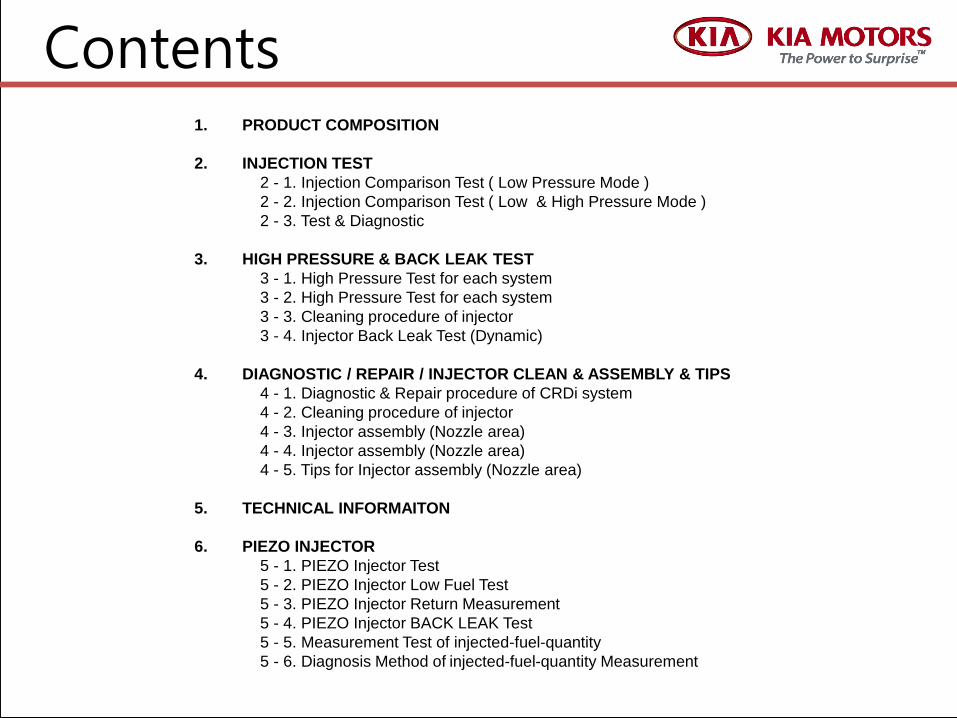
Contents1. PRODUCT COMPOSITION
2. INJECTION TEST
2 - 1. Injection Comparison Test ( Low Pressure Mode )
2 - 2. Injection Comparison Test ( Low & High Pressure Mode )
2 - 3. Test & Diagnostic
3. HIGH PRESSURE & BACK LEAK TEST
3 - 1. High Pressure Test for each system
3 - 2. High Pressure Test for each system
3 - 3. Cleaning procedure of injector
3 - 4. Injector Back Leak Test (Dynamic)
4. DIAGNOSTIC / REPAIR / INJECTOR CLEAN & ASSEMBLY & TIPS
4 - 1. Diagnostic & Repair procedure of CRDi system
4 - 2. Cleaning procedure of injector
4 - 3. Injector assembly (Nozzle area)
4 - 4. Injector assembly (Nozzle area)
4 - 5. Tips for Injector assembly (Nozzle area)
5. TECHNICAL INFORMAITON
6. PIEZO INJECTOR
5 - 1. PIEZO Injector Test
5 - 2. PIEZO Injector Low Fuel Test
5 - 3. PIEZO Injector Return Measurement
5 - 4. PIEZO Injector BACK LEAK Test
5 - 5. Measurement Test of injected-fuel-quantity
5 - 6. Diagnosis Method of injected-fuel-quantity Measurement

1
5
4
6 14
3
10
1
13
16
12
9
7
11
21
22
23
24
25
26 27
28
29
30
17
This new Injector Tester has developed in addition to in order to improve diagnostic efficiency and accuracy for vehicles equipped with Common Rail System.
Enables Injection Quantity Comparison Test under Low and High fuel pressure conditions, which it was not possible with Hi-scan/GDS/G-Scan Also Cylinder compression and Rail pressure regulator test are additionally available.
Warning :To avoid internal damage of controller by surge voltage do not connect the connector of controller with power supplied.
1. CRT-3500 Composition
7-2
8
2
15
1
19
18
31
32
33
34
1. CASE2. HP CONTROLLER (Combination)3. INJECTOR TEST TUBE ASSY 4. PIPE type A5. PIPE type B6. PIPE type C7. DUMMY INJECTOR7-2. ADAPTER (for DUMMY INJECTOR)8. COMPRESSION GAUGE9. I/CONTROL WIRE KIT (BOSCH) 10. I/CONTROL WIRE KIT (DELPHI)11. B/ LEAK CONNECTOR SET12. DUMMY RESISTER (PRV)13. DUMMY RESISTER (HP Sensor) 14. DUST CAP (for Injector ) 15. BLOCK HOSE (Injector return line)16. SPARE PARTS KIT 17. RAIL PLUG (12mm)18. RAIL PLUG (14mm) 19. USERS MANUAL
21. RPS adapter Connector (for Bosch)
22. RPS Adapter Connector(for DELPHI OLD)
23. RPS Adapter Connector (for DELPHI NEW)
24. Back Leak Test bottle 25. Low pressure gauge
Connection tube26. Low pressure gauge27. Vacuum Gauge28. Connection Adapter29. Fuel Filter Plug
(for DELPHI) 30. Connection Adapter
with Hose31. DUMMY INJECTOR (L))32. I/CONTROL WIRE KIT(PIEZO)33. Delphi Connector34. Delphi Dummy Injector

1) LOW PRESSURE MODE TEST LOW PRESSURE MODE TEST
1. Remove the injectors from engine2. Block the return line of injectors3. Install the test pipes in the rail (4ea)
and Install Test Tubes in injectors.4. Install the Back Leak bottle in the Injectors5. Install the injector control wire.6. Crank the engine until the injection amount level of 1 or 2 test tubes are close to 5.
NOTE : Rail pressure will be maintained 250~300bar automatically by vehicle’s ECU.Therefore you don’t need to use HP controller during the test.
2-1 INJECTION COMPARISON TEST ( LOW PRESSURE MODE )
Test Method : Automatic Affected vehicle : All Model ( including EURO-Ⅳ)
ECU
12
2
3
5
5
54
※ All the pipes must be cleaned before installed .
( Clean it with an air gun )
Tighten
Loosen FlushingTighten
IG on or Cranking
Install Test tubes
Flushing : Crank the engine and let the fuel leaks from the fitting area for flushing purpose.
Remove injectors and install the dummy injectors instead.
Block the fuel return line of injectors to prevent fuel leaking.
2

1) LOW & HIGH PRESSURE MODE TEST
ECU
2-2 INJECTION COMPARISON TEST (LOW & HIGH PRESSURE MODE )
Test Method : Manual (PRV Controller) / Affected vehicle : All model Exempt EURO-Ⅳ/Ⅴ model
Mode Select S/W
Pressure adjust KnobLow High
High Pressure Gauge
OPEN CLOSE
Drain Valve
Push to drain and Pull to close
1
23 4
2
holding screw
TEST PROCEDURE 1) Select MAX HIGH mode and crank engine for 2-3seconds.
2) Crank engine and adjust the rail pressure in Low and Highmode while engine cranking. - LOW = 300 ~ 350 bar- HIGH = 800 ~ 1000 bar
3) Drain the fuel from the test tube.
4) Perform test in each mode: LOW & HIGH.NOTE : Perform the test more than 2 times to get accurate data.
LOW PRESSURE MODE TEST
1) Disconnect the PRV’s & rail pressure sensor’s connector from the rail
2) Install ① Dummy Resister and ② Rail PressureSensor Dummy in each wiring connectors.
3) Connect HP controller’s leads to the ③PRV & ④ railpressure sensor.
5) Connect HP controller’s ⑤ power cable to battery.4) Crank the engine until the injection amount level
of 1 or 2 test tubes are close to target level.(5 scale in LOW, 8 scale in HIGH)
NOTE : - Rail pressure can be adjusted from 100 to 1000bar by pressure adjust knob.
- From Euro-4(09MY) model you must use rail pressuresensor dummy otherwise injector will not work whilecranking.
NOTE: Battery must be fully charged before test
5
3
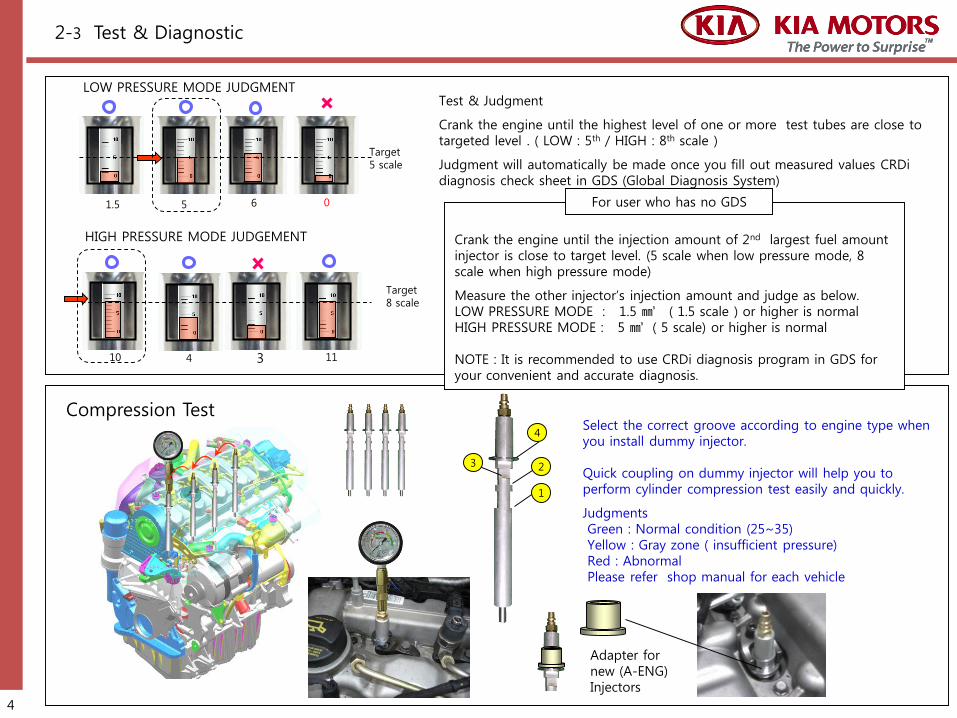
LOW PRESSURE MODE JUDGMENT
Target 5 scale
HIGH PRESSURE MODE JUDGEMENT
Target 8 scale
1.5 5 6 0
10 114 3
Test & Judgment
Crank the engine until the highest level of one or more test tubes are close to targeted level . ( LOW : 5th / HIGH : 8th scale )
Judgment will automatically be made once you fill out measured values CRDi diagnosis check sheet in GDS (Global Diagnosis System)
2-3 Test & Diagnostic
Select the correct groove according to engine type when you install dummy injector.
Quick coupling on dummy injector will help you to perform cylinder compression test easily and quickly.
Judgments Green : Normal condition (25~35) Yellow : Gray zone ( insufficient pressure) Red : AbnormalPlease refer shop manual for each vehicle
Compression Test
1
23
4
Crank the engine until the injection amount of 2nd largest fuel amount injector is close to target level. (5 scale when low pressure mode, 8 scale when high pressure mode)
Measure the other injector’s injection amount and judge as below.LOW PRESSURE MODE : 1.5 ㎣ ( 1.5 scale ) or higher is normal HIGH PRESSURE MODE : 5 ㎣ ( 5 scale) or higher is normal
NOTE : It is recommended to use CRDi diagnosis program in GDS for your convenient and accurate diagnosis.
For user who has no GDS
4
Adapter for new (A-ENG) Injectors
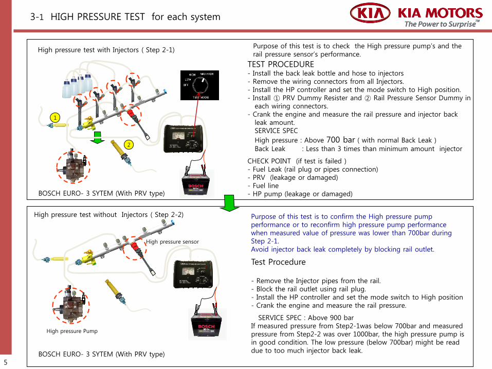
BOSCH EURO- 3 SYTEM (With PRV type)
High pressure test with Injectors ( Step 2-1)Purpose of this test is to check the High pressure pump’s and the rail pressure sensor’s performance.
TEST PROCEDURE - Install the back leak bottle and hose to injectors - Remove the wiring connectors from all Injectors. - Install the HP controller and set the mode switch to High position.- Install ① PRV Dummy Resister and ② Rail Pressure Sensor Dummy in
each wiring connectors.- Crank the engine and measure the rail pressure and injector back
leak amount.SERVICE SPEC
High pressure : Above 700 bar ( with normal Back Leak )
Back Leak : Less than 3 times than minimum amount injector
CHECK POINT (if test is failed )- Fuel Leak (rail plug or pipes connection)- PRV (leakage or damaged)- Fuel line- HP pump (leakage or damaged)
High pressure sensor
High pressure Pump
Purpose of this test is to confirm the High pressure pump performance or to reconfirm high pressure pump performance when measured value of pressure was lower than 700bar during Step 2-1. Avoid injector back leak completely by blocking rail outlet.
Test Procedure
- Remove the Injector pipes from the rail. - Block the rail outlet using rail plug. - Install the HP controller and set the mode switch to High position- Crank the engine and measure the rail pressure.
SERVICE SPEC : Above 900 barIf measured pressure from Step2-1was below 700bar and measured pressure from Step2-2 was over 1000bar, the high pressure pump is in good condition. The low pressure (below 700bar) might be read due to too much injector back leak.
BOSCH EURO- 3 SYTEM (With PRV type)
3-1 HIGH PRESSURE TEST for each system
High pressure test without Injectors ( Step 2-2)
5
1
2
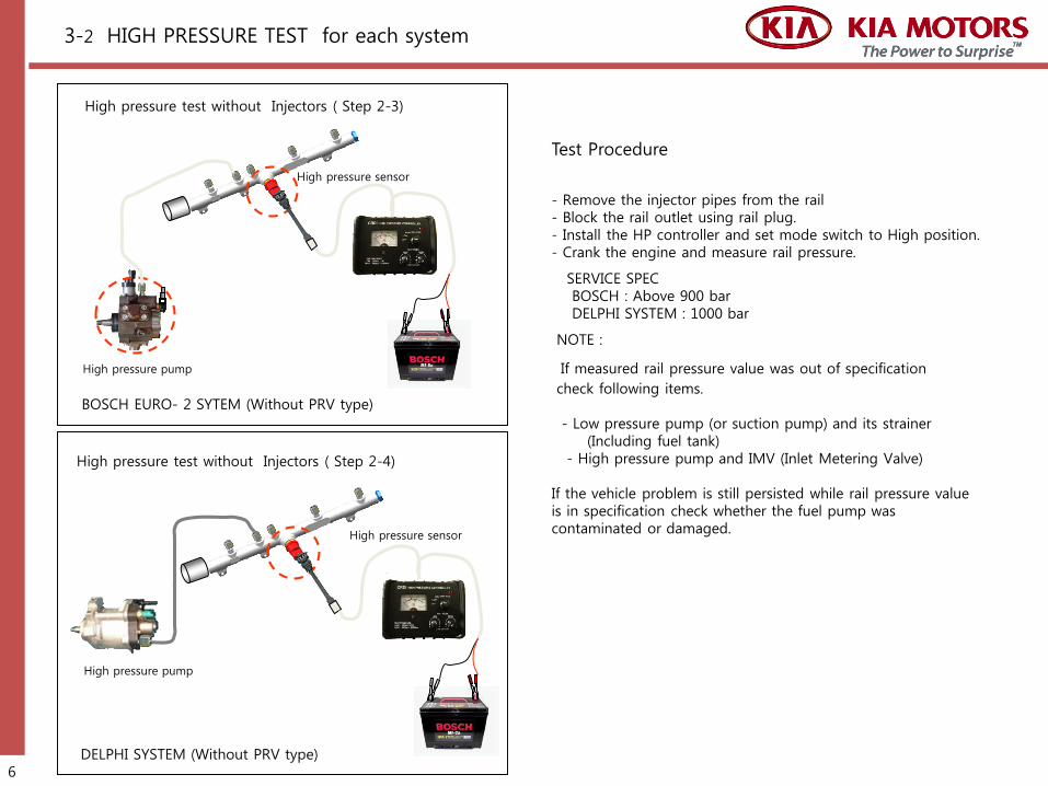
High pressure sensor
High pressure pump
High pressure sensor
High pressure pump
Test Procedure
- Remove the injector pipes from the rail - Block the rail outlet using rail plug. - Install the HP controller and set mode switch to High position.- Crank the engine and measure rail pressure.
SERVICE SPEC BOSCH : Above 900 barDELPHI SYSTEM : 1000 bar
NOTE :
If measured rail pressure value was out of specification
check following items.
- Low pressure pump (or suction pump) and its strainer(Including fuel tank)
- High pressure pump and IMV (Inlet Metering Valve)
If the vehicle problem is still persisted while rail pressure value is in specification check whether the fuel pump was contaminated or damaged.
3-2 HIGH PRESSURE TEST for each system
DELPHI SYSTEM (Without PRV type)
High pressure test without Injectors ( Step 2-3)
High pressure test without Injectors ( Step 2-4)
BOSCH EURO- 2 SYTEM (Without PRV type)
6

Fuel pump(Electric)
ⓕ
ⓐ Low Pressure Gauge ⓒ Test Tube Assayⓓ Connection Adapterⓔ Connection Adapter with Hose ⓕ Hose Clamp
ⓔ
ⓓ
ⓐ
ⓒ
Pressure GaugeElectric pump type (Bosch Type II)
Internal suction pump type (Delphi)
ⓒ
ⓖⓓⓓ
ⓑ
Electric pump type (BOSCH Type Ⅱ)
EURO-Ⅲmodel
CASEPRESSURE
(bar)JUDGMENT
1 1.5~3.5 kg/㎠ System normal
2 0 ~1.5 kg/㎠Fuel Filter (or fuel line / strainer or etc )
clogging
3 no pressure Abnormal function of fuel pump
EURO-Ⅳmodel
CASEPRESSURE
(bar)JUDGMENT
1 2.5 ~ 5 kg/㎠ System normal
2 0.5~2.0 kg/㎠Filter or fuel line clogging (pump in
good condition)
3 no pressure Abnormal function of fuel pump
Internal suction pump type ( Delphi)
CASE VACUUM JUDGMENT
1 10~20 cmHg System normal (good condition)
2 20~60 cmHgFilter or fuel line clogging (pump in good
condition)
3 0~10 cmHgAir leak in to the system or Suction pump
damage
ⓖ
37
3-3 HIGH PRESSURE TEST for each system

INJECTOR BACK LEAK TEST (DYNAMIC) 1) Remove the return hose from each injector and Install injector return hose adapter
visible tubes flasks and injector return hose plug referring to Injector back leak test (STATIC) in previous page.
2) Conduct the high pressure leak test referring to following explanation.BOSCH Type Ⅰ,Ⅱ,Ⅲ : D3EA(1.5D-ENG), D4EA(2.0D-ENG), D4FA(U-ENG), D4CB(2.5A-ENG)
3) Start engine → 3 minutes at idle → accelerate engine up to 2500 rpm and keep the 2500rpm for 2 minutes →Stop Engine after 2 minutes
4) When the test is completed, measure the amount of fuel in each flask5) Judgments
BOSCH Type Ⅰ,Ⅱ,ⅢReplace the injector which is shown more 3 times than the minimum value.
30sec / 3000rpm
stopStart 1min
30sec / 3000rpm
StopIdle
acceleration
Start2min
Normal condition #2 Injector abnormal
1 2 3 4
Service Limit 25cc
1 2 3 4
Abnormal injector
DELPHIReplace the injector which indicates exceeds 25cc.
DELPHI : J3 (2.9L)3) Connect the Hi-Scan and select the 'High Pressure Leak Test' mode. 4) Conduct the 'High Pressure Leak Test' until the Hi-Scan finish the test automatically.
or manually : Start engine → 2minutes at idle → 3 times acceleration →Stop Engine 5) For the accuracy of the test, perform the test more than twice and select
the largest amount as a measured value. ※ The flasks should be empty before the 2nd test started.
6) Judgments
58
3-4 INJECTOR BACK LEAK TEST( DYNAMIC)
1 2 3 4

Injector / EGR / TC problem
- Engine Vibration- Hesitation / jerking - Smoke emitting
Classify the symptoms
FinishTest
Diagnosis by CRT-1000Finish
NG
Enter
OK
* Injector repairs : Repair injector (replacing internal parts) if it is not recovered after cleaning. * Replace injector assembly when the internal parts are not available.
4-1. Diagnostic & Repair procedure of CRDi system
Repair or replace the part related to problem.
OK
Check the function of EGR & VGT / WGT system
NGRepair or Replace
Fuel line or pump problem
- Engine stall - Hard start or impossible to start- Fuel pump noise - DTC set ( related with pressure line )
OK
Cleaning Test
NGReplace Injector
9

DisassembledCleaning
Inspection (To identify the parts that need to replace)
AssemblingPerformance testby Injector Tester
Start
End
4-2. Cleaning procedure of injector
Clean Diesel
Repairing injector must be done in a clean and dust free environment to prevent injector contamination.
Soaking( more than 5 minutes)
Washing Rinse
Note : Do not use brush while rinse to avoid contamination
Do not interchange internal parts of injectors as it will influence on its calibration. Use only original parts to maintain the proper performance.
Thinner※ Caution: Thinner and its evaporated gas is harmful to people.
Bottle cap must be closed while soaking.
Kerosene or Diesel
10
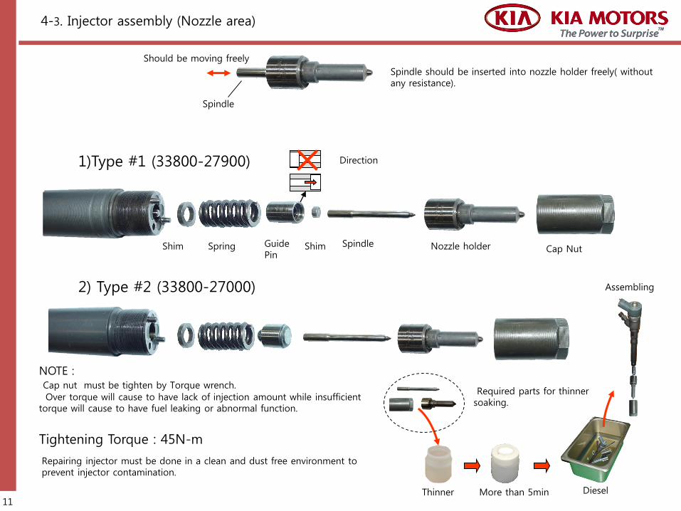
Tightening Torque : 45N-m
NOTE :Cap nut must be tighten by Torque wrench.
Over torque will cause to have lack of injection amount while insufficient torque will cause to have fuel leaking or abnormal function.
1)Type #1 (33800-27900)
2) Type #2 (33800-27000)
Direction
Shim Spring Guide Pin
Nozzle holder Cap NutShim
4-3. Injector assembly (Nozzle area)
Spindle should be inserted into nozzle holder freely( without any resistance).
Spindle
Should be moving freely
Spindle
Thinner
Required parts for thinner soaking.
More than 5min
Repairing injector must be done in a clean and dust free environment to prevent injector contamination.
Diesel
Assembling
11

3) Type #3 (DELPHI)
4-4. Injector assembly (Nozzle area)
Valve bodyReturn Spring
Control ValveShim
The purpose of the control valve on the Delphi injector is to control injection amount. It might cause incorrect injection amount and excessive back leak if the valve has stuck.
Control Valve Valve body
Return springNozzle Spindle
Cap nut
Free movement are required
Thinner
Required parts for thinner soaking
More than 5min
Tightening Torque : 45N-m
NOTE When you test injector after cleaning operate injector more than 3~4 times in high pressure mode of HP controller for bed-in and flushing.
Repairing injector must be done in a clean and dust free environment to prevent injector contamination.
Should be moving freely Control valve should be inserted into valve body freely ( without any resistance).
12

4-5. Tips for Injector assembly (Nozzle area)
3. While cleaning the injector in cleaning fluid it must be checked for free movement of the spindle in nozzle holder. It must be gently moved until there is no resistance to movement.
Free movements are required
4. When you Inserts the spindle to the nozzle holder, change the direction of scratched mark to the opposite direction of supply hole
2. Change the direction of spindle1. Remove the spindle from the nozzle holder
Most scratched marks on spindle of nozzle are due to wearing.
The damaged spindle causes friction increase and produce low or over injectionNormally , you must replace the damaged nozzle assembly or change to new injector.
But it is possible to fix the injector without replacing the parts by using the above method.Usually(100%) scratch marks match with the fuel supply hole, therefore if you change the direction of scratched area, you may save the parts without technical problem. By using the CIT- 2000 or 3000, you can get the right results.
Scratched markSpindle with C2 coating
Change the direction
Scratched mark
Fuel supply hole
Cleaning procedure of nozzle
Try to in and out the spindle for the cleaning
13

5. Technical Information
Injector Test Defected Injector
no classification and re-labeling
Process for Re-manufacturing Injectors
Repair Delivery
Production
Injector labeling Data input
Fitting the
injector
Code readout Engine manufacture
Data record
Vehicle manufacture
ECU programming with IMA data
ECU
Injector Manufacture
Class 1 2 3
Injector Test and classifications
Process for Manufacturing Injectors
Compensation of injected-fuel-quantityNew functions are added to common-rail systems to enhance the high precision of the fuel-injection system further, and ensure them for the service life of the vehicle. With injector delivery compensation (IMA), a mass of measuring data is detected for each injector during the injector manufacturing process. The data is then affixed to the injector in the form of a data-matrix code. This data is transferred to the ECU during vehicle production. While the engine is running, these values are used to compensate for deviation in metering and switching response. But Incase of re-manufactured injectors( for in-use car service), it is almost impossible to classify control and label due to technical limitation as remarked as below. - Mechanical wearing and increasing tolerance (even rest of all injectors) - There is no space for re-labeling on injector head- Different regulation between new car and in-use car (no required) - Cost saving - According to mileage of vehicle tolerance of all injectors are increased simultaneously (most of them out of control range).
The Injector Delivery Compensation system offers solutions to above situation. Thus using an unclassified repaired injector will not influence engine performance or emission level in significant ways .
14

1) Set-up Method
6-1 PIEZO Injector Test
ECU
1
2
6
5
7
Tighten
Open Nut Clean Re-tighten
Engine Cranking
39
8
4
15
※ Piezo Injector is not an previous Solenoid Type. Piezo injector making satisfy method of the high exhaust, power and precision.
※ Previous Solenoid Valve needs an oil pressure coupler to help limited movement of Piezo injector and there is a system to maintain the oil pressure coupler for the safety maintain of it. Piezo injector is high reply and power, it is also less exhaust.
■ Set-up1. Detached Injector Back Leak Line and attached as left picture by Tube. 2. Set-up the dummy resister※ Why? : If control valve of Rail is detached, ECU order to stop the fuel pump by
disconnect the line.3. Set-up the back Leak test bottle.4. Detached the injectors form engine and set up the dummy injectors. 5. Cleaning the nozzle at end of Injector by sinner6. Attached the test pipe and injector on the rail. 7. Connecting the injector drive line and the back leak measurement kit as left
picture. 8. Tighten pipe connection to stand up test tubes.9. Check all connection are right to connect included injector pipes
■ Test1. Keep ignition (engine) on until injected fuel. 2. If not to injected fuel, please check the leaking fuel in any parts.
Test Tube
- Detached injectors and set up the dummy injectors.- Set up the tube and plastic holder on the injector
return hole※ After low pressure supply by Piezo injector,
please check any fuel leaking
- Set up the pipe and tube and back leak test bottle. - Before the set up those, please clean all connections
between pipes and injectors
Dust cleaning method :- Not to open nut between injector and connection,
and littlebit injected some fuel , then dust will beleaked more.
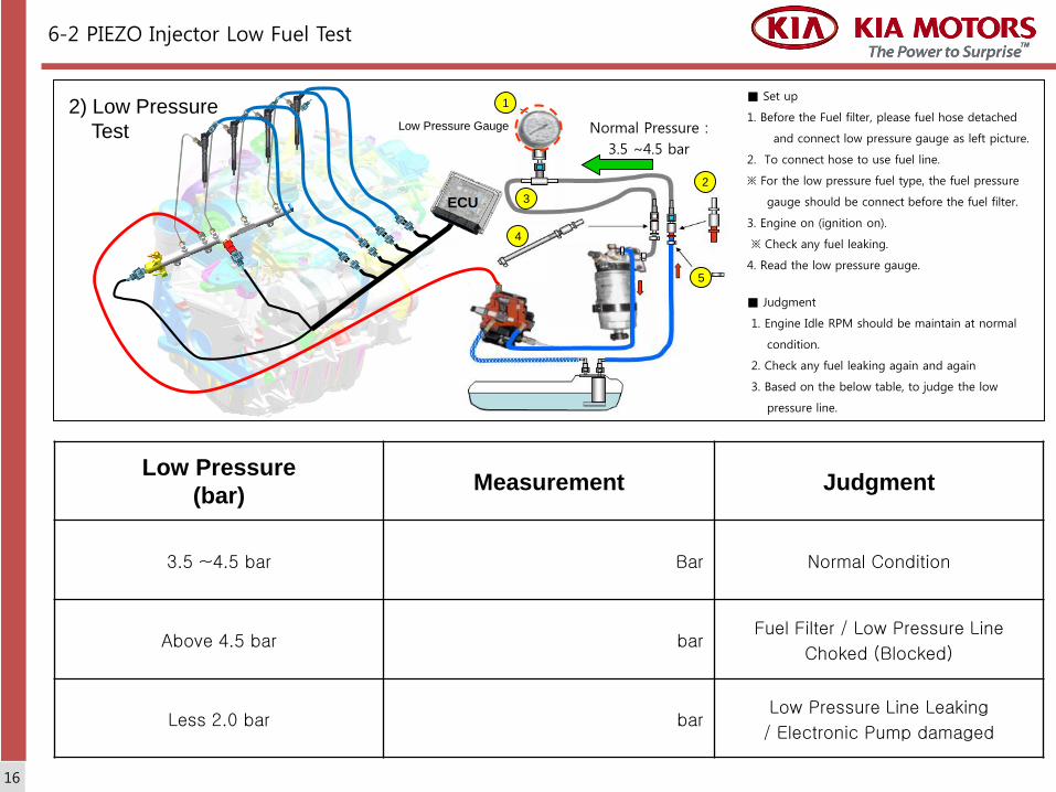
2) Low Pressure
Test
6-2 PIEZO Injector Low Fuel Test
Low Pressure
(bar)Measurement Judgment
3.5 ~4.5 bar Bar Normal Condition
Above 4.5 bar barFuel Filter / Low Pressure Line
Choked (Blocked)
Less 2.0 bar barLow Pressure Line Leaking
/ Electronic Pump damaged
1
2
3
5
Low Pressure Gauge
ECU
4
Normal Pressure :
3.5 ~4.5 bar
16
■ Set up
1. Before the Fuel filter, please fuel hose detached
and connect low pressure gauge as left picture.
2. To connect hose to use fuel line.
※ For the low pressure fuel type, the fuel pressure
gauge should be connect before the fuel filter.
3. Engine on (ignition on).
※ Check any fuel leaking.
4. Read the low pressure gauge.
■ Judgment
1. Engine Idle RPM should be maintain at normal
condition.
2. Check any fuel leaking again and again
3. Based on the below table, to judge the low
pressure line.

3) Injector Return Measurement■ Set up
1. Before the Fuel Filter, please fuel hose detached
and connect low pressure gauge on fuel return
side as left picture.
※ Some Fuel leaked from the Piezo injector side.
2. Engine on (ignition on)
※ Check any fuel leaking.
3. Read the low pressure gauge
■ Judgment
1. Engine Idle RPM should be maintain at normal
condition.
2. Check any fuel leaking again and again
3. Based on the below table, to judge the low
pressure line.
6-3 PIEZO Injector Return Measurement
Low Pressure
(bar)Measurement Judgment
3.5 ~4.5 bar bar Normal Condition
Above 4.5 bar barFuel Filter / Low Pressure Line
Choked (Blocked)
Less 2.0 bar barLow Pressure Line Leaking
/ Electronic Pump damaged
1
2
3
5
Low Pressure Gauge
ECU 4
Normal Pressure :
3.5 ~4.5 bar
17

4) PIEZO Injector Back Leak Test (Dynamic) ■ Outline (Dynamic Test)If injector back leak too much, it will be caused engine startfault, delay and etc. This test is very popular test nowadays. The test is very important test to check abrasion pressure control valve and leaking from return line of injector.
■ Set up1. Assemble the Tube and Plastic Holder on the return hole of
injector2. The low pressure supplied by the Piezo injector. So, block up
a hole of hose by the low pressure gauge. 3. After engine start, please check the leaking fuel in any parts. 4. After 1 mints idling and than to keep the 1000rpm in 30 sec,
than off the engine.5. For the accuracy test, please test at least 3 times again and
again.
■ JudgmentAs show picture, if injected-fuel-quantity much more than 3 times to compare with base injected-fuel-quantity, the injector should be consider to replace.
6-4 PIEZO Injector BACK LEAK Test
EC
U
Normal Condition #2 Injector Abnormal
1 2 3 41 2 3 4
5) PIEZP Injector Back Leak Test (Static)■ Outline (Static Test)
This test is one of best efficiency test for the injector test. If this test testing together with fuel testing, it will be is very good test to find out faulty of injector. If we check the actual pressure test of high fuel pressure pump by the Static test, it could be check the high pressure line and measuring the injected-fuel-quantity simultaneously
■ Set up1. After detached injector, please attached dummy injector2. The low pressure supplied by the Piezo injector, So, block up a hole of hose by the low
pressure gauge. 3. After back leak kit set up, please detached a connector of oil control valve of the rail
pressure sensor and high pressure pump and to connect the high pressure gauge with the rail pressure sensor and battery each by each.
4. Disconnecting the connector of rail pressure valve on CRDI side. ※ To supply power less than 5 mints to protect an electronic damage of rail pressure
control valve. 5. Connecting the test tube with rail pressure control valve line. 6. Switch on the high pressure gauge
▷Engine cracking 5 sec. ▷Measuring highest measurement of high pressure gauge (above 1,000bar)▷Measuring back leak injected-fuel-quantity of tube connected with injector return hole. (less than 5mm)
※ Piezo return quantity is almost noting compare with previous solenoid type. The solenoid type should be less than 200mm
12
3
4 ECU
66
5
18
High Pressure Gauge
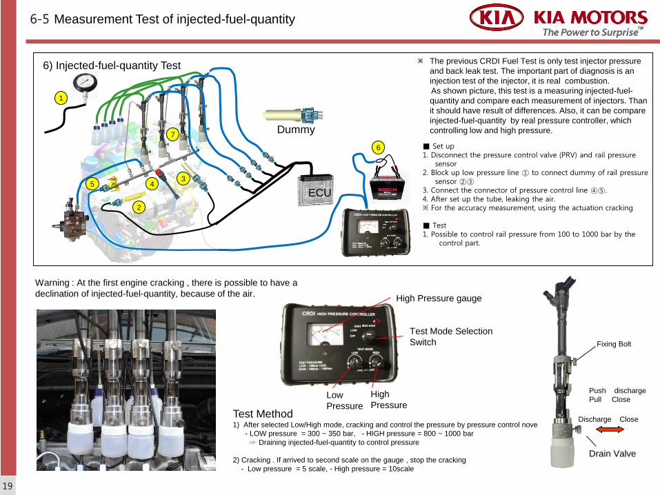
6) Injected-fuel-quantity Test
ECU
Test Mode Selection
Switch
Low
Pressure
High
Pressure
High Pressure gauge
Discharge Close
Drain Valve
Push discharge
Pull Close
2
35 4
Fixing Bolt
Test Method1) After selected Low/High mode, cracking and control the pressure by pressure control nove
- LOW pressure = 300 ~ 350 bar, - HIGH pressure = 800 ~ 1000 bar
☞ Draining injected-fuel-quantity to control pressure
2) Cracking . If arrived to second scale on the gauge , stop the cracking
- Low pressure = 5 scale, - High pressure = 10scale
6
The previous CRDI Fuel Test is only test injector pressure
and back leak test. The important part of diagnosis is an
injection test of the injector, it is real combustion.
As shown picture, this test is a measuring injected-fuel-
quantity and compare each measurement of injectors. Than
it should have result of differences. Also, it can be compare
injected-fuel-quantity by real pressure controller, which
controlling low and high pressure.
Warning : At the first engine cracking , there is possible to have a
declination of injected-fuel-quantity, because of the air.
6-5 Measurement Test of injected-fuel-quantity
1
Dummy7
19
■ Set up1. Disconnect the pressure control valve (PRV) and rail pressure
sensor2. Block up low pressure line ① to connect dummy of rail pressure
sensor ②③3. Connect the connector of pressure control line ④⑤.4. After set up the tube, leaking the air. ※ For the accuracy measurement, using the actuation cracking
■ Test1. Possible to control rail pressure from 100 to 1000 bar by the
control part.

Test judgment of Low pressure mode (300~350 bar)
Target
5 scale
Test judgment of high pressure mode (800~1000 bar)
Target
8 scale
1.5 5 6 0
10 114 3
Test and Judgment : Low Mode (300~350bar) , the result of test and high pressure mode (800~1000 bar)
1) Need to use dummy injector to prevent oil leaking at the compression and pressure test. 2) Before attach the dummy, need to check injector combined space. 3) Standard pressure is 30 ㎏/㎠ (Possible to have a difference, according to the performance
of Diesel Vehicle or old vehicle)
Cylinder Pressure Test Method
Test and Judgment
At the engine on , if 2nd injector reached target quantity out of 4 injectors, stop the engine. If
the injector is a brand new injector or a standard injector, it should be a standard.
Target injection scale : Low mode = 5 scales High mode = 8 scales
Judgment and service limitation
Low pressure test : above 1.5 scales is normal condition (In case of standard injector is on
5 scales )
Low pressure test : above 4 scales is normal condition (In case of standard injector is on
8 scales )
Warning :
- The injected-fuel-quantity is very important, because a injector has a good condition as
closed to injected-fuel-quantity of standard injector.
- It can be possible to estimate life time of the injector with the injected-fuel-quantity. It
doesn’t matter with service limitation . Strong standard measurement is good to judgment,
but it will be increased cost. Recommending to consider the vehicle's condition and model
year.
- If injected-fuel-quantity is over 30% compare with the normal condition and new injector, is
a faulty injector. (Over injected-fuel-quantity)
Piezo Injector Adapter
6-6 Diagnosis Method of injected-fuel-quantity Measurement
20