KHEPERAIV - K-Teamftp.k-team.com/KheperaIV/software/Gumstix COM Y...4.8 Gumstix Overo FireSTORM-P...
84
KHEPERAIV User manual Revision 3.0
Transcript of KHEPERAIV - K-Teamftp.k-team.com/KheperaIV/software/Gumstix COM Y...4.8 Gumstix Overo FireSTORM-P...
KHEPERAIV
User manual
Revision 3.0
Revisions history
Rev. Date
(EUR)
Description
1.0 14.03.2014 Initial creation
2.0 03.02.2015 Adapted for the Gumstix Overo FireSTORM-P
2.1 15.02.2016 Update Microphone
3.0 07.09.2016 Adapted for the Gumstix Overo FireSTORM-Y
Documentation Authors
Julien Tharin, Frédéric Lambercy and Timothée Carron K-Team S.A.
Z.I. Les Plans-Praz 28 CH-1337 Vallorbe Switzerland
E-mail [email protected]
URL www.k-team.com
Trademark Acknowledgements IBM PC : International Business Machines Corp. Macintosh : Apple Corp.
SUN Sparc-Station
: SUN Microsystems Corp.
LabVIEW : National Instruments Corp. Matlab : MathWorks Corp. Khepera : K-Team and LAMI
Legal Notice
The content of this manual is subject to change without notice All efforts have been made to ensure the accuracy of the content of this
manual. However, should any error be detected, please inform K-Team.
The above notwithstanding, K-Team can assume no responsibility for any error in this manual.
TABLE OF CONTENTS
1 INTRODUCTION .................................................................... 1
1.1 How to use this user manual ............................................ 1
1.2 Safety precautions ............................................................ 2
1.3 Recycling .......................................................................... 2
2 UNPACKING AND INSPECTION ............................................. 3
2.1 Package Content ............................................................... 3
3 THE ROBOT AND ITS ACCESSORIES ...................................... 4
3.1 Global View ....................................................................... 4
3.2 First start-up .................................................................... 6
3.3 Shutdown / Reboot / Reset .............................................. 8
3.4 The Khepera IV Robot ....................................................... 9 3.4.1 Caster wheels .......................................................................... 9 3.4.2 On/Off switch .......................................................................... 9 3.4.3 Status LED .............................................................................. 9 3.4.4 Mini-USB B connector (device) ................................................... 9 3.4.5 USB A connector (host) ............................................................. 9 3.4.6 Power supply jack .................................................................... 9 3.4.7 Charging status LED ............................................................... 10 3.4.8 Reset button .......................................................................... 10 3.4.9 Infrared sensors..................................................................... 10 3.4.10 Ultrasonic sensors ............................................................... 10 3.4.11 Camera .............................................................................. 10 3.4.12 Bottom infrared sensors ....................................................... 10 3.4.13 Contacts for docking station ................................................. 11 3.4.14 Wheels .............................................................................. 11 3.4.15 Sticker ............................................................................... 11 3.4.16 Bottom M3 Nuts .................................................................. 11 3.4.17 KB-250 Extension connectors ............................................... 11 3.4.18 Top M3 Nuts ....................................................................... 11 3.4.19 Magnets ............................................................................. 11 3.4.20 RGB LED ............................................................................ 11
3.5 Other features ................................................................ 12
4 IN DEPTH LOOK .................................................................. 13
4.1 Infrared Sensors ............................................................. 13 4.1.1 Ambient light measurement..................................................... 14 4.1.2 Reflected light measurements (proximity) ................................. 15
4.2 Ultrasonic sensors .......................................................... 16
4.3 Battery ........................................................................... 17
4.4 Contact pads ................................................................... 19 4.4.1 Reed relay location ................................................................. 20
4.5 Camera ........................................................................... 21
4.6 Microphones ................................................................... 21
4.7 Loudspeaker ................................................................... 22
4.8 Gumstix Overo FireSTORM-P COM ................................... 22
4.9 Accelerometer ................................................................ 23
4.10 Gyroscope ....................................................................... 24
4.11 USB Device (mini-USB B connector) ............................... 25
4.12 MicroSD .......................................................................... 25
4.13 RGB LED .......................................................................... 25
4.14 Motors ............................................................................ 26 4.14.1 Speed control ..................................................................... 28 4.14.2 Speed profile control ........................................................... 29 4.14.3 Position control ................................................................... 31 4.14.4 Open loop .......................................................................... 32
5 PROGRAMMING .................................................................. 33
5.1 Required hardware / software ....................................... 33 5.1.1 Required hardware ................................................................. 33 5.1.2 Required software .................................................................. 33
5.2 Software ......................................................................... 34 5.2.1 Installation of light toolchain ................................................... 34 5.2.2 Programming and light toolchain usage ..................................... 37 5.2.3 Debugging ............................................................................ 40
5.3 Full toolchain and sources .............................................. 43 5.3.1 Required software .................................................................. 43 5.3.2 Installation ............................................................................ 44 5.3.3 Full toolchain usage ................................................................ 45
5.4 Microcontroller update.................................................... 48
5.5 Packages installations .................................................... 48 5.5.1 Existing packages ................................................................... 48 5.5.2 Removing packages ................................................................ 50 5.5.3 Creating new package: ........................................................... 50
6 COMMUNICATION PROTOCOL (WITH SERVER ONLY) ......... 51
7 EXTENSION CONNECTORS .................................................. 59
7.1 J700 Pin-out ................................................................... 60 7.1.1 J701 Pin-out .......................................................................... 60
8 MECHANICAL DRAWINGS ................................................... 61
9 ANNEXES ............................................................................ 63
9.1 Using Bluetooth .............................................................. 63 9.1.1 To send a file to the robot (upload) .......................................... 65 9.1.2 To send a file to the computer (download) ................................ 65
9.2 Using WiFi ...................................................................... 66 9.2.1 Configuring Wifi ..................................................................... 66 9.2.2 Transferring files using scp ...................................................... 66 9.2.3 Remote access ....................................................................... 67 9.2.4 NFS configuration ................................................................... 68
9.3 Using the camera module ............................................... 69 9.3.1 Taking images ....................................................................... 69 9.3.2 Video Streaming .................................................................... 70 9.3.3 Programming Image processing ............................................... 71 9.3.4 Changing colors levels (whitebalance) ....................................... 71
9.4 Using microphone and speaker ....................................... 72
9.5 Development with a virtual machine .............................. 74
9.6 Using vi text file editor ................................................... 76
10 WARRANTY ......................................................................... 77
Khepera IV User Manual ver 3.0 1
1 INTRODUCTION
Thank you for buying a Khepera IV robot! The Khepera IV is a high end
table-top robot that will initiate your experience to the extraordinary world of mobile robotics. Thanks to its wealth of sensors, motors and its software
openness, you will be able to create complex behavior, making you an expert of this promising technology.
This new version of the manual is for the Gumstix Overo FireSTORM-Y mounted on the Khepera IV, using the Yocto development system. You can
check if the word “Yocto” (with Distro 1.8 or higher) is present at the end of boot (see chapter 3.2 First start-up) .
1.1 How to use this user manual
This user manual introduces the Khepera IV robot and its various operating modes.
If this user manual does not answer one of the problems you are confronted with, please consult the K-Team web site (http://www.k-team.com) and
especially the Forum and the FAQs.
Three kinds of symbols are used in this document; in order to keep you and your robot safe, please respect them:
Ignoring the mentioned warning could lead to
malfunction or reduced performance.
Ignoring the mentioned warning could lead to perpetual damage and would void the warranty.
Danger: risk of electric shock
Khepera IV User Manual ver 3.0 2
1.2 Safety precautions
Here are some recommendations on how to correctly use the robot:
Keep the robot away from wet area. Contact with
water could cause malfunction and/or breakdown. Store your robot in a stable position. This will avoid
the risk of falls, which could break it or cause
damage to a person. Use only the official charger or the cable which is
delivered with the robot. Do not try to use another
charger; this can cause irreversible damage to the battery and or the electronics.
Do not attach any connector while the robot is
powered. To avoid any damage, make all
connections when the robot power is off. Never leave the robot powered when it is unused.
When you have finished working with Khepera, turn
it off. It will save the battery life. Do not manually force any mechanical movement.
Avoid forcing by any mechanical way, the
movement of the wheels or any other part.
Never open the case. Only qualified technicians are allowed to do so.
1.3 Recycling
Think about the end of life of your robot! Parts of the robot can be recycled
and it is important to do so. It is for instance mandatory to keep batteries out of the solid waste stream. When you throw away a battery, it eventually
ends up in a landfill or municipal incinerator. This battery, which contains Lithium Polymer, can contribute to the toxicity levels of landfills or incinerator ash. By recycling the batteries through recycling programs, you
can help to create a cleaner and safer environment for generations to come. For those reasons, please take care to the recycling of your robot at the end
of its life cycle, for instance sending back the robot to the manufacturer or to your local dealer.
Thank you for your contribution to a cleaner environment!
Made in
Switzerland Contains FCC ID : U9R-W2CBW003
Khepera IV User Manual ver 3.0 3
2 UNPACKING AND INSPECTION
2.1 Package Content
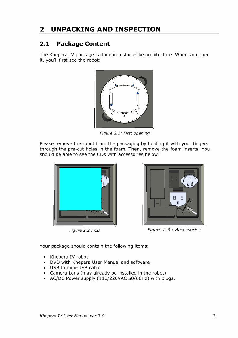
The Khepera IV package is done in a stack-like architecture. When you open it, you’ll first see the robot:
Figure 2.1: First opening
Please remove the robot from the packaging by holding it with your fingers,
through the pre-cut holes in the foam. Then, remove the foam inserts. You should be able to see the CDs with accessories below:
Figure 2.2 : CD
Figure 2.3 : Accessories
Your package should contain the following items:
Khepera IV robot
DVD with Khepera User Manual and software USB to mini-USB cable Camera Lens (may already be installed in the robot)
AC/DC Power supply (110/220VAC 50/60Hz) with plugs.
Khepera IV User Manual ver 3.0 4
3 THE ROBOT AND ITS ACCESSORIES
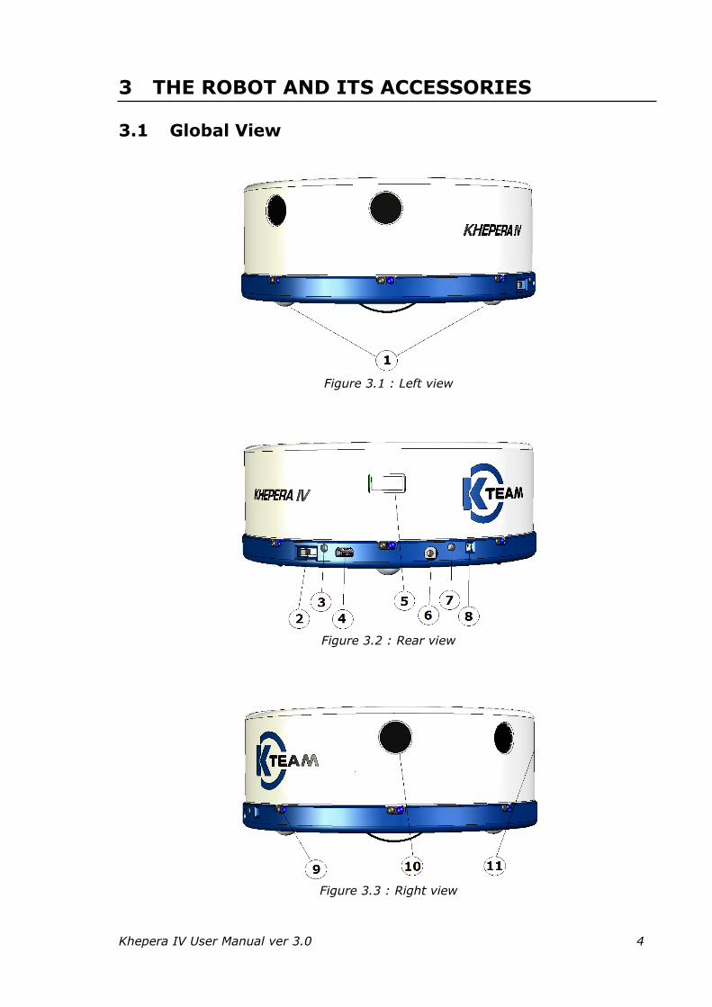
3.1 Global View
Figure 3.1 : Left view
Figure 3.2 : Rear view
Figure 3.3 : Right view
Khepera IV User Manual ver 3.0 5
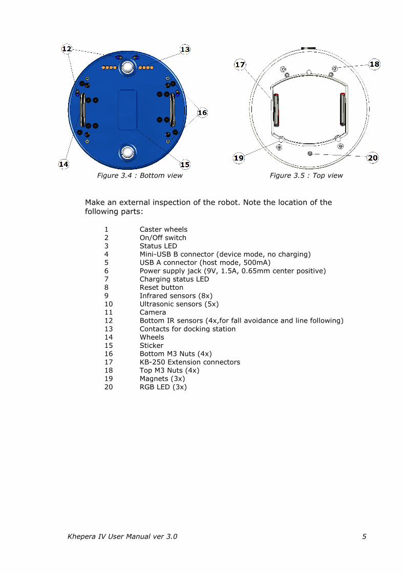
Figure 3.4 : Bottom view
Figure 3.5 : Top view
Make an external inspection of the robot. Note the location of the following parts:
1 Caster wheels
2 On/Off switch
3 Status LED
4 Mini-USB B connector (device mode, no charging)
5 USB A connector (host mode, 500mA)
6 Power supply jack (9V, 1.5A, 0.65mm center positive)
7 Charging status LED
8 Reset button
9 Infrared sensors (8x)
10 Ultrasonic sensors (5x)
11 Camera
12 Bottom IR sensors (4x,for fall avoidance and line following)
13 Contacts for docking station
14 Wheels
15 Sticker
16 Bottom M3 Nuts (4x)
17 KB-250 Extension connectors
18 Top M3 Nuts (4x)
19 Magnets (3x)
20 RGB LED (3x)
Khepera IV User Manual ver 3.0 6
3.2 First start-up
It is required, before to use the robot for the first time, to let
the battery charge completely. In order to do that, once the robot out from its packaging, please assure it is off (switch on
the outside), plug the charger into the robot jack and then into mains. Please consider a time of 5 hours for the initial charge.
Carefully screw the camera lens in its place, at the front of the robot. Please
do this operation as soon the robot is removed from its packaging to avoid any dust on the sensor. You may have to launch a test application to
correctly adjust the focus. Be sure to remove the cover of the lens in order to use it. If the robot was delivered with the lens already installed, please be sure that it’s clean. If not, please use a dry microfiber towel to clean it.
You can have console access through different ways: USB described below,
Bluetooth on chapter “9.1 Using Bluetooth” and WiFi on chapter “9.2 Using WiFi”.
1) Plug the USB cable to the computer, and the mini-USB side to the robot (connector 4 of figure 3.2).
2) Switch on the robot power. On Windows, you cannot open the serial port before.
3) Open the serial port corresponding serial port. For Windows, you can
use Teraterm (http://ttssh2.sourceforge.jp) with the parameters: 115200 baud, no parity and no flow control.
4) On Linux, the FTDI driver is installed by default; use minicom (to
install it on Ubuntu: sudo apt-get install minicom). Open a
terminal console and type (example below based on Linux): minicom -s
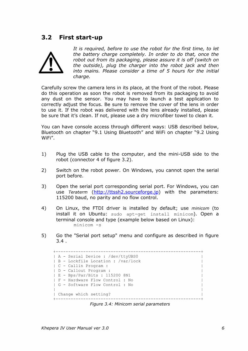
5) Go the "Serial port setup" menu and configure as described in figure 3.4 .
+----------------------------------------------------------+
| A - Serial Device : /dev/ttyUBS0 |
| B - Lockfile Location : /var/lock |
| C - Callin Program : |
| D - Callout Program : |
| E - Bps/Par/Bits : 115200 8N1 |
| F - Hardware Flow Control : No |
| G - Software Flow Control : No |
| |
| Change which setting? |
+----------------------------------------------------------+ Figure 3.4: Minicom serial parameters
Khepera IV User Manual ver 3.0 7
6) Save the settings with the command “Save setup as dfl” of the menu [configuration].
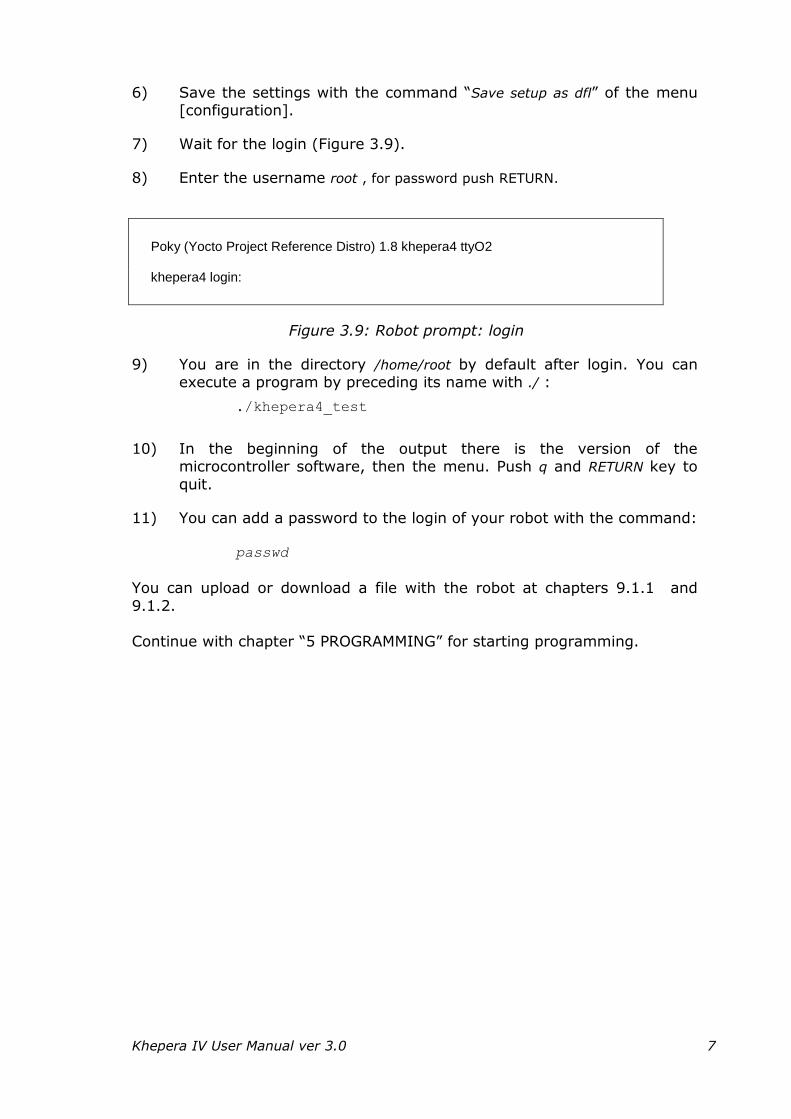
7) Wait for the login (Figure 3.9).
8) Enter the username root , for password push RETURN.
Poky (Yocto Project Reference Distro) 1.8 khepera4 ttyO2 khepera4 login:
Figure 3.9: Robot prompt: login
9) You are in the directory /home/root by default after login. You can execute a program by preceding its name with ./ :
./khepera4_test
10) In the beginning of the output there is the version of the microcontroller software, then the menu. Push q and RETURN key to
quit.
11) You can add a password to the login of your robot with the command:
passwd
You can upload or download a file with the robot at chapters 9.1.1 and
9.1.2.
Continue with chapter “5 PROGRAMMING” for starting programming.
Khepera IV User Manual ver 3.0 8
3.3 Shutdown / Reboot / Reset
Shutdown:
While logged into the console of the robot, it is better to do a proper
shutdown than just switching off the robot. This will ensure that the open files are correctly closed and settings saved.
1. Run the following command in the console:
poweroff
2. Wait 15s (if you are logged through the USB cable, you wait until Power
down appears). Then you can switch off the robot.
Reboot:
If you want to reboot, you can use:
reboot
Reset :
The robot reset can be triggered by pressing the reset button (see
Figure 3.2).
You may need to use the reset while the software is blocked and you
cannot access anymore by another connection with ssh for killing the annoying process or doing a soft reboot.
Khepera IV User Manual ver 3.0 9
3.4 The Khepera IV Robot
3.4.1 Caster wheels
There are two caster wheels below the robot. These two wheels enable the robot to be very stable, even with high payload or with long cantilever
extension modules. In return, the robot is not able to go through door sills.
3.4.2 On/Off switch
This switch will have an action on the internal regulators of the robot and
not on the battery, meaning that you can charge it even if it is off. To turn the robot on, put the switch on the inside. To turn it off, put the switch on
the outside.
3.4.3 Status LED
By default, this bicolor indication LED lets you know the state of the robot. When you turn it on, the green LED will stay on and the red light will blink until the system is ready. This LED is user-controllable.
3.4.4 Mini-USB B connector (device)
This connector lets you open a communication link between the robot and a
computer. It is not possible to charge the robot by this way.
3.4.5 USB A connector (host)
This is a USB host-capable connector. You can plug on it any USB device
you want, as long as it doesn’t draw more than 500mA of current. You can for example connect a GPS module or a memory key.
This connector has its signals shared with the KB-250
Extension connectors, meaning that you cannot use USB on Extensions at the same time as on this connector.
3.4.6 Power supply jack
This is the 0.65mm center positive jack used to charge the internal battery of the robot. Use only the provided adapter. Input voltage is 9V. Current
drawn by the robot is 1A, so a 1.5+A adapter is needed.
Khepera IV User Manual ver 3.0 10
3.4.7 Charging status LED
This is a bicolor indication LED showing you the state of the charge. There are two modes, depending if the robot is powered or not.
If the robot is off and the AC adapter is plugged, the red LED will be on as
long as the battery is charging. Once the charge terminated, the LED will turn off.
If the robot is on and the AC adapter is plugged, the red LED will be on as long as the battery is charging. Once the charge terminated, the red LED
will turn off and the green LED will turn on.
3.4.8 Reset button
This button serves to reset the whole robot, including the extension modules.
3.4.9 Infrared sensors
There are 8 infrared sensors all around the robot in order to detect obstacles or measure ambient light. With these sensors, the robot is able to see
obstacles from 2 to approx. 250mm, depending on the calibration, the ambient conditions and the obstacle color. Each sensor is separated from its neighbor by an angle of 45°.
3.4.10 Ultrasonic sensors
There are 5 ultrasonic sensors, 2 on both sides and 1 in the front of the
robot. With these sensors, the robot is able to see obstacles from approx. 250 to approx. 2500mm. Please notice that it is not possible to see nearer obstacles due to the principle of operation of this kind of sensors. There is
an angle of 45° between two sensors.
3.4.11 Camera
In the front of the robot, there is a color camera with user-changeable lens. It can be used to take pictures or movies that can be processed on board.
3.4.12 Bottom infrared sensors
Four infrared sensors are disposed on the bottom of the robot. They are used to avoid the robot from falling down but can also be used to follow a
line.
Khepera IV User Manual ver 3.0 11
3.4.13 Contacts for docking station
The Khepera IV has some apparent contacts below its body meaning that you could use a docking station to charge its battery or to communicate
with it. It’s also possible to imagine to develop an extension which would be below the robot, for example a mechanical base with tracks. The signals
that are provided are: Battery out (controlled by a reed relay), 9V in, I2C.
3.4.14 Wheels
The robot is differential driven, with 2 wheels equipped with O-ring. The wheels are driven by DC motors with encoder and gearbox.
3.4.15 Sticker
Here you’ll find the serial number of your robot.
3.4.16 Bottom M3 Nuts
There is the possibility to fix an extension to the robot from below.
3.4.17 KB-250 Extension connectors
These two connectors are used to connect extension modules to the robot.
The pin-out is accordingly to KB-250, with some minor improvements. You can re-use the Khepera III or KoreBot extension modules (but not the Kh3
Gripper).
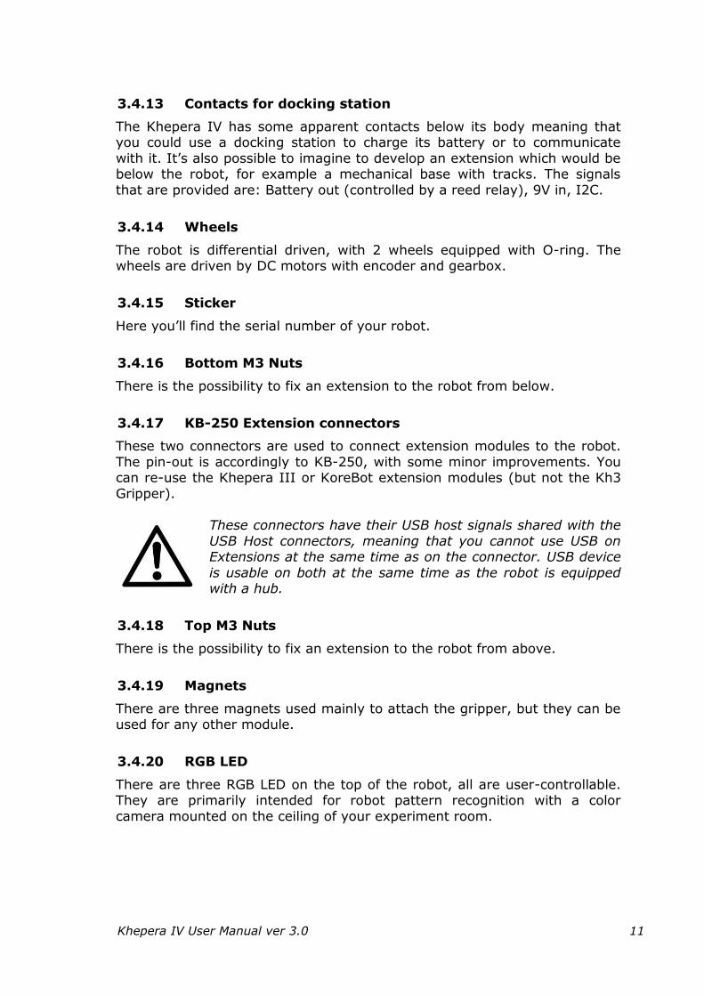
These connectors have their USB host signals shared with the
USB Host connectors, meaning that you cannot use USB on Extensions at the same time as on the connector. USB device
is usable on both at the same time as the robot is equipped with a hub.
3.4.18 Top M3 Nuts
There is the possibility to fix an extension to the robot from above.
3.4.19 Magnets
There are three magnets used mainly to attach the gripper, but they can be used for any other module.
3.4.20 RGB LED
There are three RGB LED on the top of the robot, all are user-controllable. They are primarily intended for robot pattern recognition with a color
camera mounted on the ceiling of your experiment room.
Khepera IV User Manual ver 3.0 12
3.5 Other features
Since the Khepera III, we added a lot of functionalities in this new robot:
No need for KoreBot : a powerful Linux embedded board is included
by default (Gumstix Overo FireSTORM COM)
No need for KoreConnect : use the USB device, WiFi or Bluetooth connection instead
800MHz ARM Cortex-A8 Processor with C64x Fixed Point DSP core
512 MB RAM, 512 MB NAND Flash and additional 4GB for data
Embedded WiFi and Bluetooth with internal antennas
Powerful and long lasting internal Lithium-Polymer battery
(3400mAh, 7.4V, 25.16Wh)
Two 100 to 10’000 Hz microphones
One 400 to 20’000 Hz 0.7W Loudspeaker
3-axis accelerometer
3-axis gyroscope.
Although the internal battery is not removable, it is possible to charge it from 3 places:
From the jack
From the contacts situated below the robot
From the KB-250 extensions connectors.
The max payload of the robot is 2kg.
Operating temperature range of the robot is 0 to 55°C.
Battery charging temperature range is 0 to 30°C.
Never attempt to charge it by higher temperature.
Khepera IV User Manual ver 3.0 13
4 IN DEPTH LOOK
4.1 Infrared Sensors
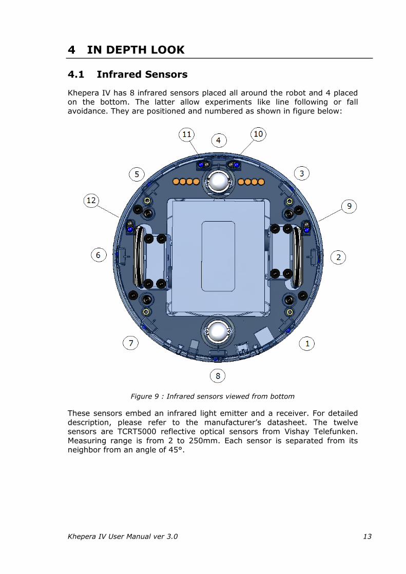
Khepera IV has 8 infrared sensors placed all around the robot and 4 placed on the bottom. The latter allow experiments like line following or fall avoidance. They are positioned and numbered as shown in figure below:
Figure 9 : Infrared sensors viewed from bottom
These sensors embed an infrared light emitter and a receiver. For detailed
description, please refer to the manufacturer’s datasheet. The twelve sensors are TCRT5000 reflective optical sensors from Vishay Telefunken.
Measuring range is from 2 to 250mm. Each sensor is separated from its neighbor from an angle of 45°.
Khepera IV User Manual ver 3.0 14
This kind of sensors allows two measures:
The normal ambient light. This measure is made using only the
receiver part of the device, without emitting light with the emitter. A new measurement is made every 5ms. The value returned at a given
time is the result of the last measurement made. The light reflected by obstacles (=proximity). This measure is made
by emitting light using the emitter part of the device. The returned value is the difference between the measurement made while emitting light and the light measured without light emission (ambient
light). A new measurement is made every 5ms. The value returned at a given time is the result of the last measurement made.
4.1.1 Ambient light measurement
Ambient light measurement is strongly influenced by the robot’s environment. Depending on the light source type, color, and distance,
ambient light measurement profile might vary. It is not recommended to use light source with large emission in the infrared range, as this could
confuse the IR sensors. Value range is 0 to 1023, 0 stands for no light and 1023 for full light.

Khepera IV User Manual ver 3.0 15
4.1.2 Reflected light measurements (proximity)
Sensors are mainly meant to detect obstacles around the Khepera. Measurements for reflected light depend on objects reflectivity and on
ambient light conditions. Object colors, materials and surfaces do have an influence on the sensor’s response. Moreover, as any sensor, IR sensors are
subject to environmental noise. For all these reasons, graphics below are given for information only and should not be considered as references.
Value range is 0 to 1023, 0 stands for no obstacle, 1023 for very near obstacle. Here’s an example of value with a white paper used as an obstacle:
Figure 10 : IR value vs Distance
The IR value never falls to 0 as, even with no obstacle, the IR reflects on the floor and adds a static value. As all the sensors are not exactly the
same, the solution is to perform a calibration of the IR with no obstacle in front. With this calibration, the user will be able to improve detection of obstacle at distance greater than 20cm.
Khepera IV User Manual ver 3.0 16
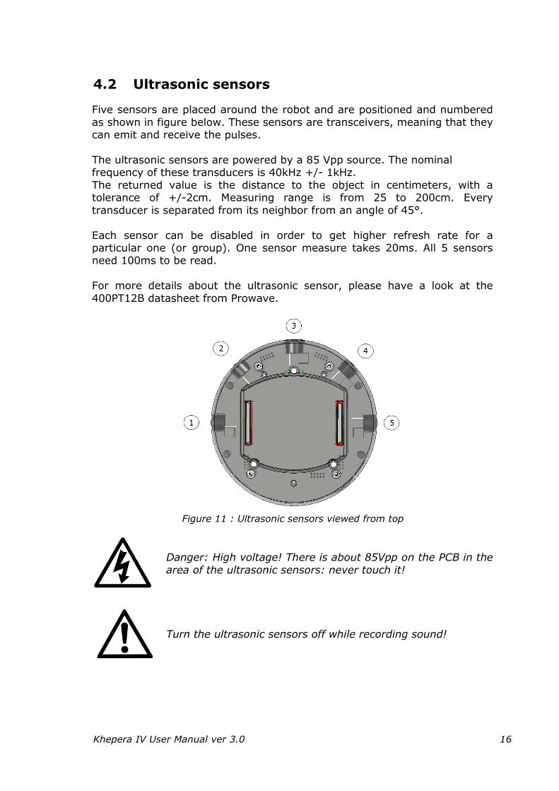
4.2 Ultrasonic sensors
Five sensors are placed around the robot and are positioned and numbered
as shown in figure below. These sensors are transceivers, meaning that they can emit and receive the pulses.
The ultrasonic sensors are powered by a 85 Vpp source. The nominal frequency of these transducers is 40kHz +/- 1kHz.
The returned value is the distance to the object in centimeters, with a tolerance of +/-2cm. Measuring range is from 25 to 200cm. Every
transducer is separated from its neighbor from an angle of 45°.
Each sensor can be disabled in order to get higher refresh rate for a particular one (or group). One sensor measure takes 20ms. All 5 sensors need 100ms to be read.
For more details about the ultrasonic sensor, please have a look at the
400PT12B datasheet from Prowave.
Figure 11 : Ultrasonic sensors viewed from top
Danger: High voltage! There is about 85Vpp on the PCB in the
area of the ultrasonic sensors: never touch it!
Turn the ultrasonic sensors off while recording sound!
Khepera IV User Manual ver 3.0 17
4.3 Battery
The Khepera IV is equipped with an internal non-removeable Lithium-
Polymer battery. It is built in a 2S1P configuration, giving 7.4V nominal, 8.4V charging voltage and a capacity of 3400mAh.
Nominal voltage : 7.4V
Cut-off voltage : 6.0V
Charging voltage : 8.4V
Nominal capacity : 3400mAh
Max discharge current : 3400mA (1C)
Charging current : 1100mA
Time for a complete charge : about 4 to 5 hours
Using its embedded power, the robot is able to run completely
autonomously during more than 5 hours with motors at 100% and 7 hours with motors off, running with a basic configuration. When additional
equipment is used, the autonomy is reduced as Khepera’s extensions like the gripper rely on Khepera’s batteries as a power source. There is no specific power management system on the Khepera. When the
battery voltage falls under 6V, the battery opens itself the circuit to avoid a deep discharge of the cells. Users can implement their own software power
management system to handle extensions to shutdown properly before this case happens.
The battery can be charged from 3 places: From the jack
From the contacts situated below the robot From the KB-250 extensions connectors.
The battery is charged through an internal battery charge IC that needs 9V of input voltage. During its constant current phase, the battery is charged
with a 1.1A current.
To charge from the jack, only use the provided AC adapter.
To charge via the contact pads situated below the robot, only use the 9Vin and Ground pads. Please refer to the contact pads section for more
information. To charge via the KB-250 extensions connectors, use only pin 44 of J701
and a ground pin. Max voltage is 9.5VDC.
Khepera IV User Manual ver 3.0 18
The charge status is indicated on the charging status LED. During the charge, the red LED turns on. The red LED will turn off when the charge is complete.
The charge will not be enabled if the external supply is plugged when the
battery is above 7.95V. In this case, the red LED will never turn on, neither the green LED.
If the robot is turned on, the dsPIC will check the end-of-charge status in the Fuel Gauge. When this status is set (~5-10 second after the red LED
turns off), the charge status LED will turn green.
If the battery cuts off after a complete discharge, the user
needs to make a complete charge with the robot on (wait for the charge status LED becoming green) to update correctly the remaining capacity.
The Fuel Gauge (DS2781) returns different information available by the
application: - Battery status register (see DS2781 datasheet for details) - Absolute remaining capacity (unit 1.6mAh)
- Relative remaining capacity (0-100%) - Battery current (updated every 3.5s). The resolution is 78.125[uA]. A
positive value means a charging current. - Average current (updated every 28s) - Temperature with a resolution of 0.125°C.
- Battery voltage with a resolution of 9.76mV
The battery current is measured through a 20[mΩ] resistor.
The battery temperature is accurate only when the charge is not active. During the charge, internal component heat will perturb the measure. You need to consider that the returned value is approximately 10°C higher
than the real battery temperature (especially when charging current is 1A).
As the charge is not automatically protected against temperature, you have to verify it before starting a charge.
Battery charging temperature range is 0 to 30°C. Never
attempt to charge it by higher temperature. Do not try to charge if room temperature is higher than 30°C.
Khepera IV User Manual ver 3.0 19
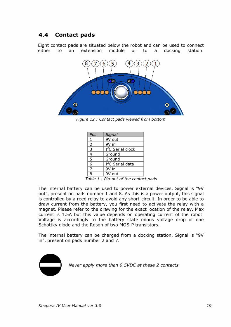
4.4 Contact pads
Eight contact pads are situated below the robot and can be used to connect
either to an extension module or to a docking station.
Figure 12 : Contact pads viewed from bottom
Pos. Signal
1 9V out
2 9V in
3 I2C Serial clock
4 Ground
5 Ground
6 I2C Serial data
7 9V in
8 9V out
Table 1 : Pin-out of the contact pads
The internal battery can be used to power external devices. Signal is “9V
out”, present on pads number 1 and 8. As this is a power output, this signal is controlled by a reed relay to avoid any short-circuit. In order to be able to
draw current from the battery, you first need to activate the relay with a magnet. Please refer to the drawing for the exact location of the relay. Max
current is 1.5A but this value depends on operating current of the robot. Voltage is accordingly to the battery state minus voltage drop of one Schottky diode and the Rdson of two MOS-P transistors.
The internal battery can be charged from a docking station. Signal is “9V
in”, present on pads number 2 and 7.
Never apply more than 9.5VDC at these 2 contacts.
Khepera IV User Manual ver 3.0 20
Communication with the outside is done via I2C. Clock signal is on pad 3, while data signal is on pad 6. Level is 0 to 3.3V. Use level adapter if needed.
Ground signal is present on pins 4 and 5.
The signals are routed in a symmetrical way so that if the robot is in the
wrong direction on the docking, no damage occurs.
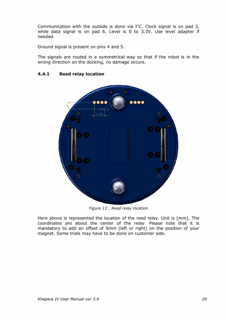
4.4.1 Reed relay location
Figure 13 : Reed relay location
Here above is represented the location of the reed relay. Unit is [mm]. The
coordinates are about the center of the relay. Please note that it is mandatory to add an offset of 5mm (left or right) on the position of your
magnet. Some trials may have to be done on customer side.
Khepera IV User Manual ver 3.0 21
4.5 Camera
The Khepera IV is equipped with a front color camera, disposed below the
front ultrasonic sensor. The sensor is a MT9V034C12ST from Aptina. It’s a 1/3” WVGA CMOS sensor.
Active imager size : 4.51x2.88mm
Active pixels : 752x480 The default lens has a focal length of 2.1mm, with IR cut filter and fixed focus. The mounting thread is M12x0.5. Diagonal field of view is 150°, horizontal is 131° and vertical is 101°. See chapter 9.3 “Using the camera
module” for usage.
4.6 Microphones
The Khepera IV is equipped with an amplified Microphone PU0414HR5H-SB from Knowles. It’s directly connected to the Overo Analog right SUB MIC
input. See chapter 9.4 “Using microphone and speaker” for usage.
Gain 20dB
Sensitivity (typ) -22dbv/Pa
Directivity Omnidirectional
Supply voltage 2.5V
Khepera IV User Manual ver 3.0 22
4.7 Loudspeaker
A SMS-1308MS-2-R loudspeaker from PUI Audio is mounted on the Khepera
IV. This speaker is driven by a 1W low distortion power amplifier. The speaker is connected on the HSOLF audio output of the OVERO. The OVERO
can also mute the amplifier with GPIO64 (0 = MUTE, 1 = ampli on). Speaker Power 0.7W (max 1W)
Impedance 8 Ohm
Output SPL 88dBA
Distortion (max) 5%
Resonant frequency 850Hz ±20%
Frequency range 400 ~ 20’000Hz
See chapter 9.4 “Using microphone and speaker” for usage.
4.8 Gumstix Overo FireSTORM-P COM
The Khepera IV was designed to embed a Gumstix Overo processor board. The computer-on module mounted by default in the Khepera IV is the
Gumstix Overo FireSTORM-P COM. This computer-on-module has an additional DSP to perform special tasks, Bluetooth & WiFi capabilities (SMD antenna mounted on the Khepera).
Architecture: ARM Cortex-A8
NAND Flash: 512MB
Processor: Texas Instruments OMAP3730 @ 800MHz
DSP: C64x Fixed Point DSP 660,800 Mhz
Wifi: 802.11 b/g/n included
Bluetooth: version 3.0 included
The Gumstix is provided with a Linux system already installed (Angström
distribution). More information on the Overo can be found on the Gumstix website
(www.gumstix.com).
Khepera IV User Manual ver 3.0 23
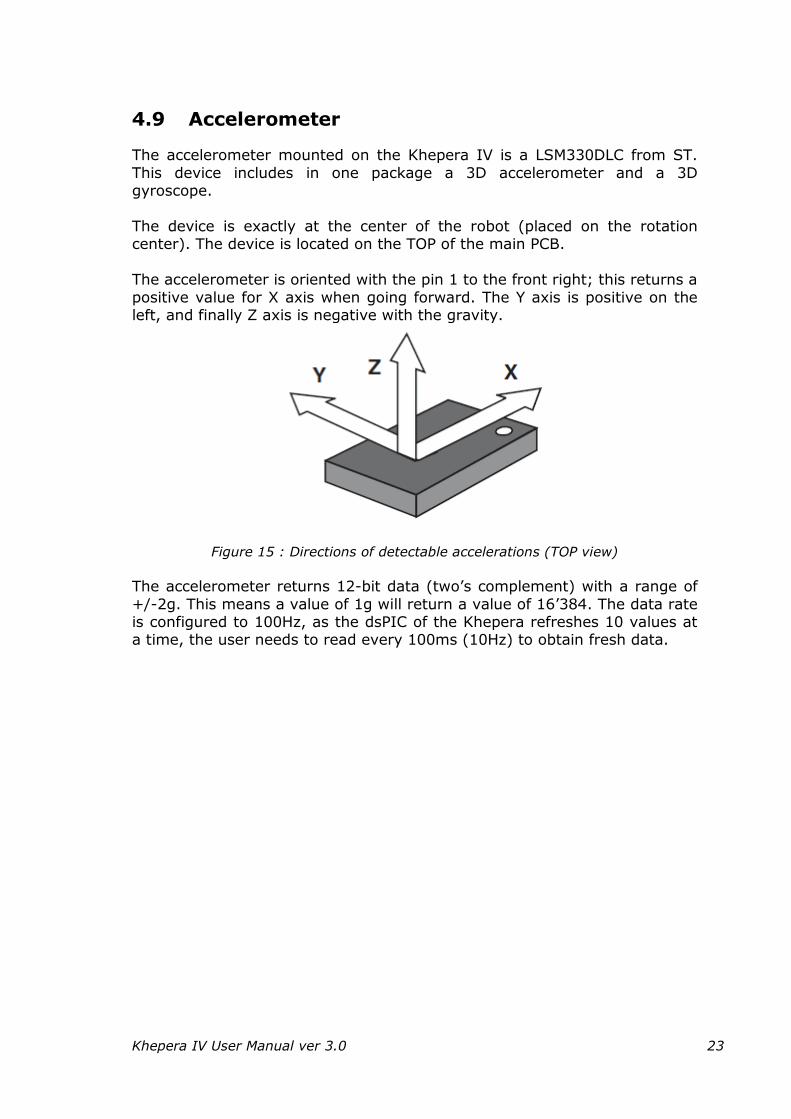
4.9 Accelerometer
The accelerometer mounted on the Khepera IV is a LSM330DLC from ST.
This device includes in one package a 3D accelerometer and a 3D gyroscope.
The device is exactly at the center of the robot (placed on the rotation center). The device is located on the TOP of the main PCB.
The accelerometer is oriented with the pin 1 to the front right; this returns a
positive value for X axis when going forward. The Y axis is positive on the left, and finally Z axis is negative with the gravity.
Figure 15 : Directions of detectable accelerations (TOP view)
The accelerometer returns 12-bit data (two’s complement) with a range of
+/-2g. This means a value of 1g will return a value of 16’384. The data rate is configured to 100Hz, as the dsPIC of the Khepera refreshes 10 values at a time, the user needs to read every 100ms (10Hz) to obtain fresh data.
Khepera IV User Manual ver 3.0 24
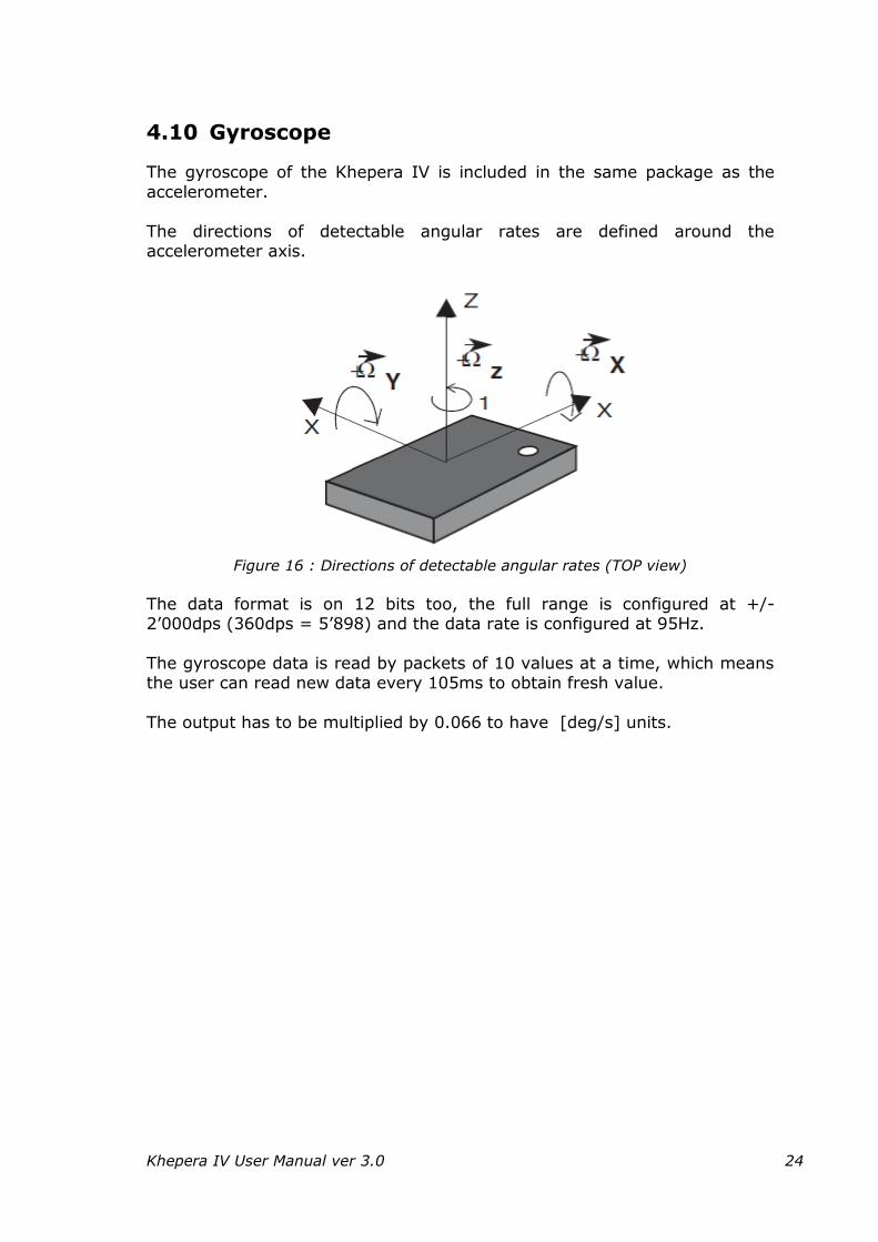
4.10 Gyroscope
The gyroscope of the Khepera IV is included in the same package as the
accelerometer.
The directions of detectable angular rates are defined around the accelerometer axis.
Figure 16 : Directions of detectable angular rates (TOP view)
The data format is on 12 bits too, the full range is configured at +/-2’000dps (360dps = 5’898) and the data rate is configured at 95Hz.
The gyroscope data is read by packets of 10 values at a time, which means the user can read new data every 105ms to obtain fresh value.
The output has to be multiplied by 0.066 to have [deg/s] units.
Khepera IV User Manual ver 3.0 25
4.11 USB Device (mini-USB B connector)
A mini-USB B connector provides access to a USB-to-serial adapter
(FT234XD from FTDI) to access directly to the ttyS2 of the Gumstix. Using a terminal provides the access to the boot of the system.
When connecting a computer to this connector for the first time, your local system will ask for driver. FT234XD driver can be found at
http://www.ftdichip.com/Products/ICs/FT234XD.html.
4.12 MicroSD
A 4GB MicroSD card is provided inside the Khepera IV. The robot will boot
on it and use this card. It already contains the OS, kernel and boot files. See chapter “0
Uploading the kernel and the file system” to rebuild it if needed.
4.13 RGB LED
Three RGB LED (19-337/R6GHBHC-A01/2T from Everlight) are mounted on the TOP of the main board. Each of these LED has a light guide on it.
The LED are driven by a dedicated LED driver (LTC3219 from Linear) which
provides a resolution of 6 Bits (0-63) for each color. These LED can be used to locate the Khepera IV with a camera (at the
ceiling) and differentiate each robot (in swarm application). As the LED are placed on a isosceles triangles, the direction of the robot can also be
detected. The physical positions of these LED are shown in the Mechanicals Drawing
chapter.
Khepera IV User Manual ver 3.0 26
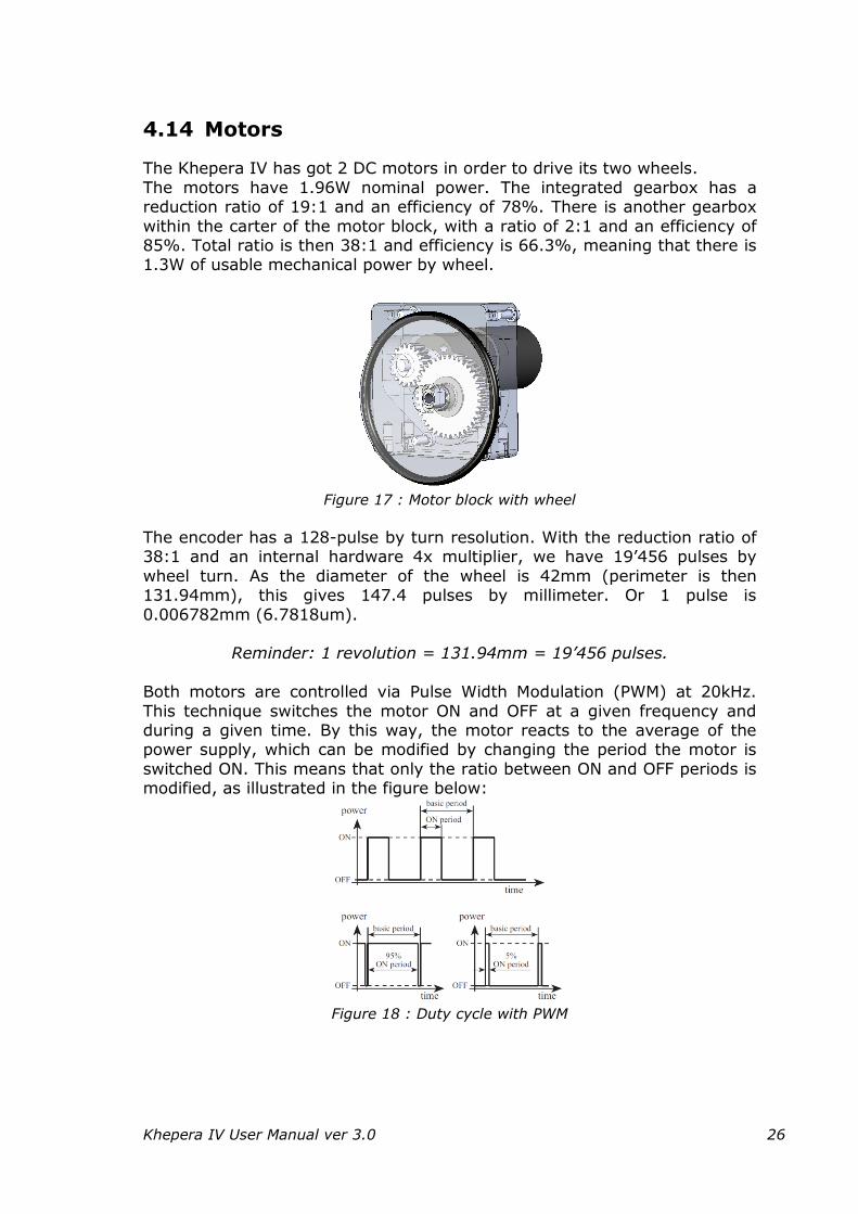
4.14 Motors
The Khepera IV has got 2 DC motors in order to drive its two wheels.
The motors have 1.96W nominal power. The integrated gearbox has a reduction ratio of 19:1 and an efficiency of 78%. There is another gearbox
within the carter of the motor block, with a ratio of 2:1 and an efficiency of 85%. Total ratio is then 38:1 and efficiency is 66.3%, meaning that there is 1.3W of usable mechanical power by wheel.
Figure 17 : Motor block with wheel
The encoder has a 128-pulse by turn resolution. With the reduction ratio of 38:1 and an internal hardware 4x multiplier, we have 19’456 pulses by
wheel turn. As the diameter of the wheel is 42mm (perimeter is then 131.94mm), this gives 147.4 pulses by millimeter. Or 1 pulse is
0.006782mm (6.7818um).
Reminder: 1 revolution = 131.94mm = 19’456 pulses.
Both motors are controlled via Pulse Width Modulation (PWM) at 20kHz.
This technique switches the motor ON and OFF at a given frequency and during a given time. By this way, the motor reacts to the average of the power supply, which can be modified by changing the period the motor is
switched ON. This means that only the ratio between ON and OFF periods is modified, as illustrated in the figure below:
Figure 18 : Duty cycle with PWM
Khepera IV User Manual ver 3.0 27
The dsPIC calculates the PWM to apply to each motor in speed control and position control. The user can override the PID and apply directly a desired PWM to the motor using the open loop command.
Default PID settings applied to the Khepera IV controller are: Kp: 10
Ki: 5
Kp: 1
These values will be used by the PID speed controller. In position control, the PID is the same as the position controller calculates a speed order then
calls the speed controller to reach this order. User can modify these values to improve behaviour to his particular use.
When selecting a type of control, this mode will be applied to both motors. It’s not possible to set the left motor in speed control and the right motor in
another mode.
To put the motor in idle mode (no more current drawn by the motors), use the open loop control with parameters set to 0. In speed control, even with a parameter of 0, the controller will struggle against any movement.

Khepera IV User Manual ver 3.0 28
4.14.1 Speed control
Both DC motors are controlled by a PID controller executed every 10ms in an interrupt routine of the dsPIC. Every term of this controller
(Proportional, Integral, Derivative) is associated to a constant, setting the weight of the corresponding term: Kp for the proportional, Ki for the
integral, Kd for the derivative.
The controller has as input the speed value of the wheels and controls the motor to keep this wheel speed. The speed modification is made as quick as possible, in an abrupt way. No limitation in acceleration is considered in this
mode.
The speed unit corresponds to the difference measured in position between the two controllers’ routine (10ms). Here’s the formula to convert the speed unit to metric unit.
Refresh time: 10ms
Wheel diameter: 42mm
Revolution resolution: 19’456 [pulses]
pulses
pulses
pulses
Wheel
fresh
pulsesv
v
Nbt
vsmmSpeed
678181.0
19456
42
01.0/
Re
Formula to calculate real speed from the measured value
The minimum speed order to ensure a correct control is 5 (=3mm/s). Under this value, the control is not very stable with default PID parameters. User
can modify the PID to try to improve the behavior for this kind of very low speed.
The maximum speed order is approximately 1’200 (=813mm/s). It’s still
possible to move the robot faster if the control mode is set to open loop. In this case, the maximum speed will vary with the battery voltage and the payload.
Khepera IV User Manual ver 3.0 29
4.14.2 Speed profile control
This type of control uses the same PID as standard speed controller but adds an acceleration ramp to travel from the actual speed to the new speed
order.
The ramp used in this mode can be configured with the speed profile parameters. Three parameters define the ramp:
Acc_Inc: value of increment to add or subtract every Acc_Div +1
control loop (value from 1 to 255).
Default = 3
Acc_Div: defines the number of control loops where no increment is added to the speed order. For example, a value of 0 means that at every control loop, the speed will be
increased by Acc_Inc. A value of 4, means that every 5 control loops (50ms) the speed will be modified.
(value from 0 to 255) Default = 0. Min_Speed_Acc: this parameter defines the minimum speed used by the
controller. This value avoids setting a speed too low where the controller is not efficient. If the order value is
smaller than this parameter, the controller will automatically limit the speed to Min_Speed_Acc. Do not set values lower than 1.
Default = 20.
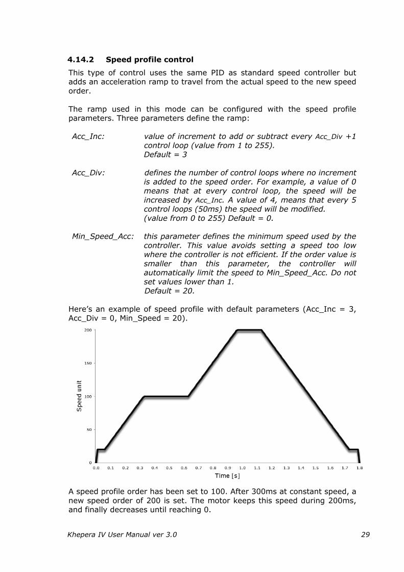
Here’s an example of speed profile with default parameters (Acc_Inc = 3, Acc_Div = 0, Min_Speed = 20).
A speed profile order has been set to 100. After 300ms at constant speed, a
new speed order of 200 is set. The motor keeps this speed during 200ms, and finally decreases until reaching 0.
Khepera IV User Manual ver 3.0 30
This curve corresponds to the order sent to the PID speed controller. The real speed of the motor will depend on the payload and the PID reactivity.
A higher Acc_Div parameter will increase the time between two steps to allow the PID to reach the speed order. A value of 0 means that the
effective motor speed will always be late on the order during the acceleration.
This type of control must be preferred to the simple speed profile in order to avoid high current peaks and preserve the mechanical parts. The user
needs to adapt the parameters Acc_Inc and Acc_Div to match the desired behavior (high Acc_Inc for a reactive profile, high Acc_Div for a smooth
profile).
Khepera IV User Manual ver 3.0 31
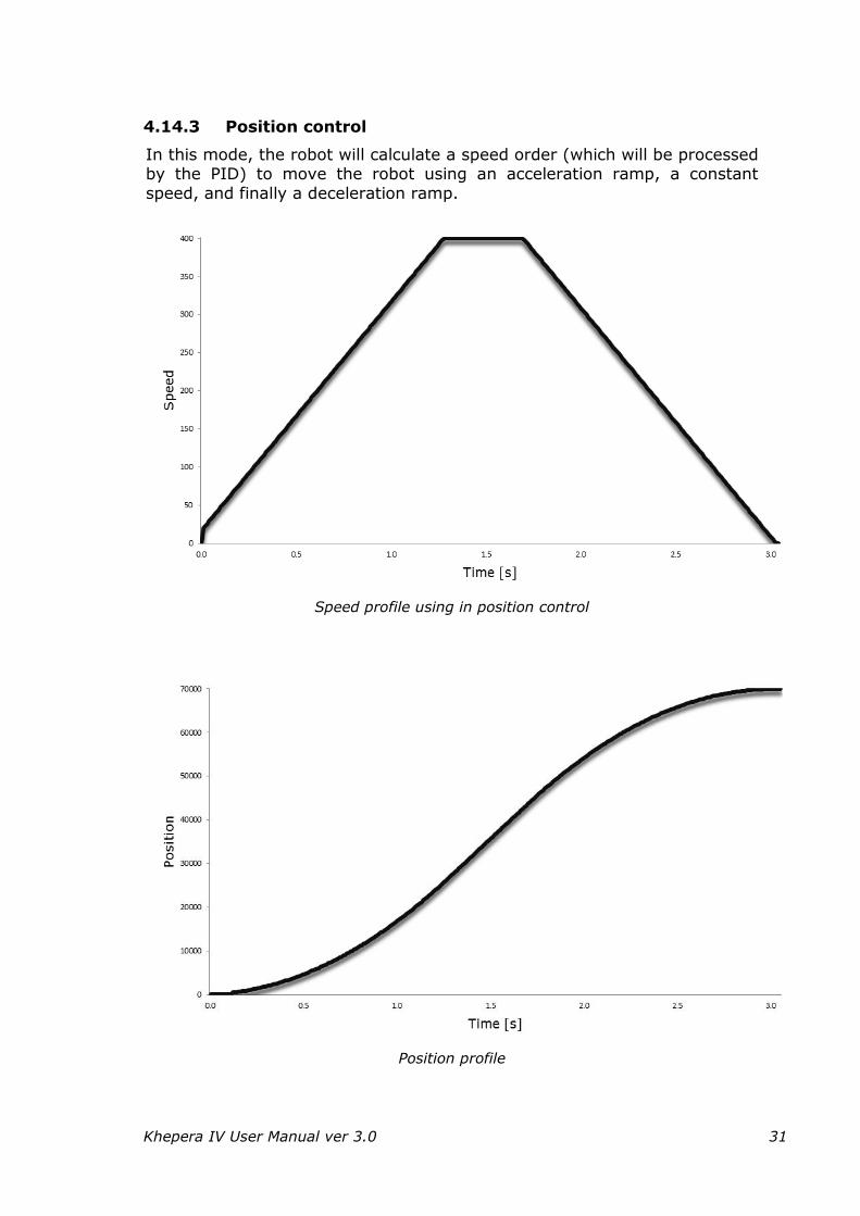
4.14.3 Position control
In this mode, the robot will calculate a speed order (which will be processed by the PID) to move the robot using an acceleration ramp, a constant
speed, and finally a deceleration ramp.
Speed profile using in position control
Position profile

Khepera IV User Manual ver 3.0 32
This example shows a travel of 475mm (70’000 pulses) using the default parameters.
The position control mode uses the same parameter as the speed profile control to calculate the acceleration ramp. The Min_Speed_Acc parameter is
used only at the start. When reaching the target position, the speed is limited by Min_Speed_Dec parameter (default = 1).
In addition to these three parameters, the travel speed can be configured through “Speed_Order” parameter (default = 400).
Finally, the “Pos_Margin” parameter defines the threshold when the position
controller stops completely the motor (set 0 to the speed controller). A low margin will increase the precision, but will add an instability to the control. It is not recommended to set this parameter below the default value (10).
To calculate the real distance travelled by the motor, use the formula
below: Wheel diameter: 42mm
Revolution resolution: 19’456 [pulses]
453.14719456
42 pulses
pulses
pulses
Wheelpulses
PP
NbPmmPosition
The position is stored in a signed 32 bits data, which means that the maximum position order is +/- 231 pulses (=14’563m).
When performing straight travel (same distance on each wheel), the best
solution is to reset the position encoder before sending the target position command.
4.14.4 Open loop
This control mode disables the PID controller and sets directly the PWM to the two motors. This can be useful if the application wants to calculate its own PID.
The range of this command is +/- 2’940 where 2’940 correspond to 100%
of PWM in forward direction and -2’940 in backward direction. If the application wants to disable the motor (to decrease current
consumption), the best way is to use this mode and set the PWM to 0. The motor will be in free wheel mode.
Khepera IV User Manual ver 3.0 33
5 PROGRAMMING
5.1 Required hardware / software
The required hardware and software to use the board and develop programs are described below.
5.1.1 Required hardware
Computer with Bluetooth, WiFi, or USB port with Linux or Linux
emulation (with a virtual machine, you can also use the
toolchain. See chapter 9.5 "Development with a virtual
machine”).
Khepera IV robot (with Yocto version 1.8 see “3.2 First start-up”)
5.1.2 Required software
Required free space:
3 GB on /opt or on your account (for light toolchain)
50 MB on user account (~/)
Required files:
1) Linux OS (kernel 2.6.x) on the computer with the following
packages installed:
gcc : GNU C compiler
minicom : terminal emulation
lrzsz : communication package
You can use a virtual machine if you don’t have Linux installed (see chapter “9.5 Development with a virtual machine”).
2) From the DVD:
Cross-compiler light : poky-glibc-i686-khepera4-image-cortexa8hf-
vfp-neon-toolchain-1.8.sh
Robot library sources : libkhepera_2.1.tar.bz2
Remarks: you can K-Team directly for up to date version.
Khepera IV User Manual ver 3.0 34
5.2 Software
The following sub-chapters explain the software installation and the application development with the board.
Two development packages are available:
Light toolchain
Full toolchain and sources: for advanced users; kernel modifications; packages creation/addition
In the subsequent paragraphs, only the light tool chain is explained.
The full toolchain is described in the following chapter “5.3 Full toolchain and sources”. With a virtual machine, you can also use the toolchain from another operating system (see chapter 9.5 “Development with a virtual
machine”).
5.2.1 Installation of light toolchain
The installation of the software required to use the board and the development tool is described in the next sub-chapters.
Below are listed the files needed to install the light toolchain. These files are available on the DVD or from the Internet URL: http://ftp.k-
team.com/KheperaIV/software/
From light_toolchain/ folder:
Light toolchain (cross-compiler only):
poky-glibc-i686-khepera4-image-cortexa8hf-vfp-neon-toolchain-1.8.sh
From library/ folder:
Board library sources: libkhepera_2.X.tar.bz2 *
* where X is the release version (may change without notice)
5.2.1.1 Installation of the development directory
The development directory will be the base folder for your development. It contains links and scripts to easily use the cross-compiler
to make your programs.
Create a new development folder ~/khepera4_development in your home directory and enter into it. You can use the following commands, assuming
you are in a console.
mkdir ~/khepera4_development
cd ~/khepera4_development
Khepera IV User Manual ver 3.0 35
5.2.1.2 Installation of the cross-compiler (light toolchain)
Install the cross-compiler either in /opt or in your own account if you don't have root access:
chmod +x poky-glibc-i686-khepera4-image-cortexa8hf-vfp-neon-toolchain-1.8.sh
sudo ./poky-glibc-i686-khepera4-image-cortexa8hf-vfp-neon-toolchain-1.8.sh
Follow the instructions of the installation program using default settings (or
choosing a folder that you have writing rights if you don't have root access).
You can check if the installation is correct by running the cross-compiler. Firstly make the environment variables available (to be done every time you
open a new terminal to cross-compile a program):
source /opt/poky/1.8/environment-setup-cortexa8hf-vfp-neon-poky-linux-gnueabi
then check the version of the cross-compiler:
arm-poky-linux-gnueabi-gcc --version
=> The last command should return:
arm-poky-linux-gnueabi-gcc (GCC) 4.9.2
5.2.1.3 Installation of the robot library
The library is already installed on the robot. To install the library on your development system, follow the following instructions:
Extract the library libkhepera_2.X.tar.bz2 in your development folder:
tar -xjf libkhepera_2.X.tar.bz2 -C ~/khepera4_development
You can recompile the whole library by running the following commands in the libkhepera-2.X folder:
cd ~/khepera4_development/libkhepera-2.X
make clean
make all
If you modified the library (any file in src/), you will have to transfer the file build-khepera-3.18.18-custom/lib/libkhepera.so.2.X to your robot, overwriting /usr/lib/libkhepera.so.2.X.
Khepera IV User Manual ver 3.0 36
The board library contains these files and directories:
build-khepera-3.18.18-custom/ compiled library and headers
doc/ documentation (API: start in doc/html/index.html)
src/ source code of the library
src/tests examples and tests source code
template/ template program
Makefile Makefile for all
README.kteam readme file
You can find an updated version of the library from the following FTP
site:
http://ftp.k-team.com/KheperaIV/software/library/
Khepera IV User Manual ver 3.0 37
5.2.2 Programming and light toolchain usage
5.2.2.1 Application development
A template program prog-template.c is available in the robot library in the folder libkhepera-2.X/template.
You can start your code into the template program and use the
following commands to build it. The command runs the Makefile script to compile and build the executable program. Type in a console to build the template program:
cd ~/khepera4_development/libkhepera-2.0/template
make
=> The “template” file is the executable output file.
You can transfer the program to the robot by USB, Bluetooth or WiFi (see chapters “3.2, 9.1 or 9.2.1”).
Then execute it on the robot by running:
./template
The Application Programming Interface documentation of the library is available at:
~/khepera4_development/libkhepera-2.X/doc/html/index.html
Remarks:
If you modify the program name, you will have to modify its occurrences in the Makefile file.
You can find many examples of source code in:
~/khepera4_development/libkhepera-2.X/src/tests Try kh4_example.c or the big khepera4_test.c
They are compiled with the command below. To compile only the examples, run:
make clean_tests
make tests
See next sub-chapter for using Eclipse guide for editing source code. See chapter 5.2.3 for debugging your program.
Khepera IV User Manual ver 3.0 38
5.2.2.2 C/C++ Programming: using GUI source code editor Eclipse
You can use also Eclipse as source code editor. See instructions below how to install and use it.
1. Install the Java Runtime Environment (JRE) if not already installed with these commands:
sudo add-apt-repository ppa:webupd8team/java
sudo apt-get update
sudo apt-get install oracle-java8-installer
2. Download the linux version of "Eclipse IDE for C/C++ Developers
(includes Incubating components)" from (for Ubuntu users, don't install with apt-get because, the apt-get version is older):
http://www.eclipse.org/downloads/packages/eclipse-ide-cc-developers/mars2
3. Extract the Eclipse program file:
tar -xzf eclipse-cpp-mars-2-linux-gtk.tar.gz –C ~/
You can also create a link to the start file:
sudo ln -s ~/eclipse/eclipse /usr/bin/eclipse
4. You should have installed the latest version of the khepera toolchain (light or full). You can check by opening a terminal and with the
command (one line):
/usr/local/khepera4-yocto/build/tmp/sysroots/i686-
linux/usr/bin/armv7a-vfp-neon-poky-linux-gnueabi/arm-poky-
linux-gnueabi-gdb --version
which should return: GNU gdb (GDB) 7.6.2
5. Run eclipse and at the "Workspace launcher" window, choose where you would like to put your project. Then close Welcome window.
Go to file menu “File => C Project” or C++; for running a C++ on the robot and choose a Project Name (ex: test). Then push next button.
6. In the next window "C Project", press the "Advanced Settings" button and on the “C/C++ Build => Settings”,
In “Cross Settings”: enter:
Prefix: arm-poky-linux-gnueabi-
Path: /opt/poky/1.8/sysroots/i686-pokysdk-linux/usr/bin/arm-poky-linux-
gnueabi/
7. On “Cross GCC Compiler” Includes => Include paths, add:
/opt/poky/1.8/sysroots/cortexa8hf-vfp-neon-poky-linux-gnueabi/usr/include
8. On Miscellaneous, replace "Other flags" with
-c -march=armv7-a -mfloat-abi=hard -mfpu=neon -mtune=cortex-a8 --sysroot=/opt/poky/1.8/sysroots/cortexa8hf-vfp-neon-poky-linux-gnueabi
Khepera IV User Manual ver 3.0 39
9. On “the Cross GCC Linker”, on Miscellaneous, replace “Linkers flags” with:
-march=armv7-a -mfloat-abi=hard -mfpu=neon -mtune=cortex-a8 --
sysroot=/opt/poky/1.8/sysroots/cortexa8hf-vfp-neon-poky-linux-gnueabi
10.On “Cross GCC Linker => Libraries” at "Libraries (-l), add khepera with the + button on the upper right
11.At "Libraries search path", add :
/opt/poky/1.8/sysroots/cortexa8hf-vfp-neon-poky-linux-gnueabi/usr/lib
12.Choose “C/C++” Build menu at the left. Choose Release under the
configuration list on the right. Repeat the steps above for this configuration from 6.
13. Press “Finish” button.
14. Go to menu “File => New => Source file” choose test.c as filename
15. Close the Welcome window with its cross at the upper left.
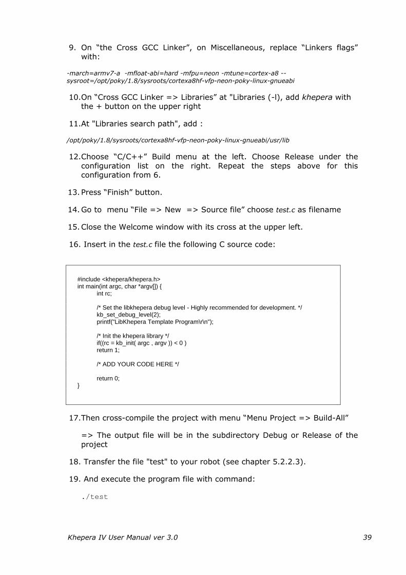
16. Insert in the test.c file the following C source code:
#include <khepera/khepera.h> int main(int argc, char *argv[]) { int rc; /* Set the libkhepera debug level - Highly recommended for development. */ kb_set_debug_level(2); printf("LibKhepera Template Program\r\n"); /* Init the khepera library */ if((rc = kb_init( argc , argv )) < 0 ) return 1; /* ADD YOUR CODE HERE */ return 0; }
17.Then cross-compile the project with menu “Menu Project => Build-All”
=> The output file will be in the subdirectory Debug or Release of the
project
18. Transfer the file "test" to your robot (see chapter 5.2.2.3).
19. And execute the program file with command:
./test
Khepera IV User Manual ver 3.0 40
5.2.2.3 Transferring files
You can transfer files to and from the robot by different means. The default one is USB (see chapter 3.2). You have also Bluetooth (chapter 9.1).
But WiFi is the fastest way (chapter 9.2.1).
5.2.3 Debugging
You can debug a program you made directly in the console on the robot or remotely.
5.2.3.1 Debugging on the robot
The debugger is already installed on the robot (check with command: gdb --version).
Your program must be cross-compiled with the option –g. Edit your Makefile and replace the flag -O2 by -g.
Transfer to the robot the compiled program and its source file. And run for debugging it:
gdb YOUR_PROGRAM
The basic commands are: r : run n : next: one step in the program; enter in subroutines
s : one step in the program b line/function : break at line/function
delete break : delete breakpoint number until line : continue until line c : continue
l : list code q : quit gdb
h : help; you can have all the commands here
A common sequence of debugging can be:
to list the code with l
set a breakpoint at the beginning of main with b main
run the program with r
execute a step with n
display a variable with p VAR_NAME
execute next step with n
continue to the end with c
quit with q.
Khepera IV User Manual ver 3.0 41
5.2.3.2 Remote debugging
The debugger server is already installed. (you can check with the command gdbserver --version).
Your program must be cross-compiled with the option –g. Edit your
Makefile and replace the flag -O2 by -g. Run the gdbserver with your cross-compiled program and an unused port
number as argument (here 1234): gdbserver --multi :1234 YOUR_PROGRAM
Go to the folder where you cross-compiled your program
You can use the debugger in command line or with ddd GUI:
Command line:
Execute for running the debugger on the computer:
source /opt/poky/1.8/environment-setup-cortexa8hf-vfp-neon-poky-linux-gnueabi
arm-poky-linux-gnueabi-gdb YOUR_PROGRAM
In this debugger, set parameter and connect to the remote gdb with these two commands:
set sysroot /opt/poky/1.8/sysroots/cortexa8hf-vfp-neon-poky-linux-gnueabi
target extended-remote YOUR_KHEPERA4_IP_ADDRESS:1234
With GUI:
On your computer, install ddd the debugger GUI with :
sudo apt-get install ddd
Launch ddd with (one command line only):
ddd --debugger arm-poky-linux-gnueabi-gdb YOUR_PROGRAM
In the window at the bottom where the (gdb) prompt is, run these two commands:
set sysroot /opt/poky/1.8/sysroots/cortexa8hf-vfp-neon-poky-linux-gnueabi
target extended-remote YOUR_ KHEPERA4_IP_ADDRESS:1234
The sequence of debugging and also the commands are the same as described above in chapter 0.
You can even send your program to the robot with the gdb commands:
remote put hostfile targetfile
set remote exec-file targetfile
where hostfile and targetfile is the same name of your new program to be debugged.
For quitting the debugger and remote, execute commands monitor exit,
then disconnect and finally quit.
Khepera IV User Manual ver 3.0 42
Tips for using the advantage of the GUI:
o For setting a breakpoint, double-click on the line you want to put it, just before the line number or right click at the same place or choose
“Set Breakpoint”.
o With the floating menu, you have the different commands for
debugging.
o You can add a watch on a variable by clicking with the right mouse
button on the variable and choose “Display VARIABLE_NAME”.
5.2.3.3 Remote debugging with Eclipse
You can also remotely debug your program with Eclipse (see chapter
5.2.2.2 for a proper installation). Follow instructions below:
On Eclipse menu 'Run' => Debug Configurations' , 'C++ Remote
Application' => double click on test Debug is created.
In the 'Main' tab => “C/C++ application”, enter: Debug/test On “Connection”: press “New” button and choose “SSH”.
In the next window, in Host name insert the IP address of your robot and press “Finish” button.
Under Connection, on "Remote Absolute File Path for C/C++
Application" modify to /home/root/test In the Debugger tab, in 'Main' tab change 'GDB Debugger' to
/opt/poky/1.8/sysroots/i686-pokysdk-linux/usr/bin/arm-poky-linux-gnueabi/arm-poky-linux-gnueabi-gdb
On 'Shared Libraries' tab add /opt/poky/1.8/sysroots/cortexa8hf-vfp-neon-
poky-linux-gnueabi/usr/lib Then press Debug, enter root as "User ID" and no password.
Choose and enter 2 times a master password Accept the Rsa
In the console of Eclipse, where gdb is running type with Return at the end:
set sysroot /opt/poky/1.8/sysroots/cortexa8hf-vfp-neon-poky-linux-gnueabi
Debug step by step. You can go again into the settings, and select "Release" configuration when
your program has been fully debugged.
You can run the program from the robot (with a remote terminal) or with Eclipse GUI.
After having set the Debug configuration, the parameters are also available for the run.
Just go to the Run menu and then choose “Run”.
In the lower part of the Eclipse window, you will see the output of your program in the Console tab.
Khepera IV User Manual ver 3.0 43
5.3 Full toolchain and sources
The full toolchain is for advanced users who would like to modify the
kernel, rebuild the image system or develop new packages for the robot.
Remarks: Prior knowledge of Linux, its kernel and Yocto / Bitbake tools is highly recommended.
5.3.1 Required software
Required free space:
50GB on /usr/local
50 MB on user account ( ~/ )
Required files:
Full toolchain : online at http://ftp.k-team.com/KheperaIV/software
Linux packages: see http://www.yoctoproject.org/docs/current/yocto-project-qs/yocto-
project-qs.html
Khepera IV User Manual ver 3.0 44
On Ubuntu Linux distribution, you can use the following command to install all the required packages in one time:
sudo apt-get install gawk wget git-core diffstat unzip texinfo gcc-multilib \build-essential chrpath
socat libsdl1.2-dev xterm
Included in the DVD-ROM of the package:
Cross-compiler and “Yocto” tools sources : khepera-yocto-kbX.Y.tar.bz2 *
Board library sources : libkhepera_X.Y.tar.bz2 *
Files for uploading file system :
flash, MLO, compressed file system
* where X.Y is the release version (may change without notice)
(NOT INCLUDED: khepera4-yocto-2.0-fulltools.tar.bz2 ; should be requested sending an email to [email protected] )
5.3.2 Installation
Install the development directory as explained in chapter 5.2.1.1:
“Installation of the development directory” if not already done.
1) Extract the cross compiler sources khepera-yocto-2.0-kbX.Y.tar.bz2 in /usr/local with the command:
sudo tar -xjf khepera4-yocto-2.0-kbX.Y.tar.bz2 -C /usr/local
Remark: you must put the tools there because there are
hardcoded links. You have to overwrite the light
tools if they were already installed.
2) You can check if the installation is correct by running the cross-compiler.
Firstly make the environment variables available then check the version of the cross-compiler:
/usr/local/khepera4-yocto-2.0/build/tmp/sysroots/i686-linux/usr/bin/arm-poky-linux-
gnueabi/arm-poky-linux-gnueabi-gcc –version
=> The last command should return:
arm-poky-linux-gnueabi-gcc (GCC) 4.9.2
3) Install the board library as explained in chapter 5.2.1.3: “Installation of the
robot library”.

Khepera IV User Manual ver 3.0 45
5.3.3 Full toolchain usage
5.3.3.1 Rebuilding the whole system
To rebuild the toolchain system, the image file and the kernel, execute the following instructions:
1. In a console, in the directory /usr/local/khepera4-yocto-2.0, source the following file to have access to the environment setup:
export TEMPLATECONF=meta-khepera4/conf source ./poky/oe-init-build-env
2. With the following commands you can rebuild the whole system: Cleaning : bitbake -c cleansstate khepera4-image
Rebuild: bitbake khepera4-image
=> The output files will be stored in:
/usr/local/khepera4-yocto-2.0/build/tmp/deploy/images/overo
Five main type of files will then be built:
the bootloader: u-boot.img
the kernel: zImage-overo.bin
the kernel device tree: zImage-omap3-overo-*.dtb
its modules: modules-overo.tgz
the file system: khepera4-image-overo.tar.bz2
Remarks: You may find updated version of these software at:
http://ftp.k-team.com/KheperaIV/software/
With the chapter 5.3.3.3 “Uploading the kernel and the file system”, you can upload these files to the robot.
You can find more information about bitbake, the tool for executing task and managing metadata here:
http://www.yoctoproject.org/docs/2.0.1/bitbake-user-manual/bitbake-user-manual.html
Information about the Yocto tools is available here:
- Linux distribution of the robot: http://www.yoctoproject.org
- Gumstix documentation: http://www.gumstix.org
Khepera IV User Manual ver 3.0 46
5.3.3.2 Kernel modification
You can modify the kernel here by accessing to its menu with these commands:
cd /usr/local/khepera4-yocto/build/tmp/work/overo-poky-linux-
gnueabi/linux-gumstix/3.5.7-r0/git
and configure the kernel with:
make ARCH=arm menuconfig
copy ".config" file to /usr/local/khepera4-yocto/poky/meta-gumstix/recipes-
kernel/linux/linux-gumstix-3.5/overo/defconfig (defconfig is the new filename)
Then you rebuild it and the file system by executing these commands at the
root of the Khepera tools:
cd /usr/local/khepera4-yocto-2.0
export TEMPLATECONF=meta-khepera4/conf source ./poky/oe-init-build-env bitbake -c clean virtual/kernel
bitbake virtual/kernel
(may take up to 30 min depending of your computer)
=> The new kernel uImage file will be located at: /usr/local/khepera-yocto-2.0/tmp/deploy/glibc/images/overo/ uImage- overo.bin
Also build the filesystem image: bitbake -c clean khepera4-image
bitbake khepera4-image
=> The new filesystem will be located at: /usr/local/khepera-yocto-2.0/tmp/deploy/glibc/images/overo/khepera4-image-overo.tar.bz2
You can now upload the files to the robot with the next chapter 5.3.3.3:
“Uploading the kernel and the file system”.
Khepera IV User Manual ver 3.0 47
5.3.3.3 Uploading the kernel and the file system
You may need to reinstall the OS file of your robot if you want to
upgrade or if something went wrong. It is done by modifying the kernel, filesystem and other files on the micro-SD card inserted in the Gumstix.
All the data on the robot will be lost after running the
following instructions!
The below procedure should only be done by an advanced user or technician. Please notice that opening the robot will
void the warranty.
Material needed:
Computer with micro SD reader MLO from DVD
(software/micro_SD/partition_copy/boot.tar.bz2) or K-Team's
ftp HDDRawCopy1.10Portable.exe and
KH4_microsd_HddRawCopyTool_2016.05.09.imgc from DVD or K-Team's ftp software/micro_SD/clone
1) There is already a micro-SD card in the robot. Carefully open the robot
by unscrewing the 4 screws number 16 of figure 3.4 and remove the micro SD card.
If you want to restore everything, start for easy cloning 2) or 3) for each partition. Otherwise continue from 4) and transfer only the new files you want.
2) Clone: use HDDRawCopy1.10Portable.exe and the clone on DVD software\micro_SD\partition_copy to put the clone on the micro SD.
Then got to 5).
3) At first you will need to make 2 partitions on your micro-SD card. Backup all the data on your microSD card before.
Follow the chapters "Partitioning the Card", "Formatting the New Partitions" and "Installing the Boot Files" the instructions there:
http://www.gumstix.org/create-a-bootable-microsd-card.html
4) You will take the khepera4-image-overo-20160416155308.rootfs.tar.bz2 * * where 20160416155308 is the release version; may change without notice.
5) from K-Team ftp or from your full tools directory (see chapter 5.3.3.2):
/usr/local/khepera4-yocto-2.0/build/tmp/deploy/images/overo
6) Insert the micro-SD and carefully put the cover and screws back.
Khepera IV User Manual ver 3.0 48
5.4 Microcontroller update
You can reflash the micro-controller of the Khepera robot with a new
firmware.
Transfer the files kh4_bootloader2.tar.bz2 containing the files kh4_firmware_B-05.hex that are on the DVD in software/bootloader to your robot (see chapter “5.2.2.3 Transferring files”).
And run:
tar –xjf kh4_bootloader2.tar.bz2 cd kh4_bootloader2
./kh4_bootloader –f kh4_firmware_B-05.hex
Remark: B-05 is the version of the firmware. It may change without notice.
5.5 Packages installations
With Yocto, you can easily cross-compile existing packages or add your
own ones. You can list installed packages on the board with the command:
rpm –qa
5.5.1 Existing packages
a) The best way if the robot is connected to internet is to install directy the
compiled package from the Gumstix repository:
smart update
smart install PACKAGE_NAME
The packages are there : https://packages.gumstix.com/fido/rpm/
You can also download them from the url above and install them offline as in
following paragraph b) 3).
b) If you want to modify it or build it yourself, follow these instructions:
1) Check if there is already a recipe package in
/usr/local/khepera4-yocto-2.0/poky/meta-*
If it is present, you can compile it by running in the /usr/local/khepera4-yocto-2.0
directory:
export TEMPLATECONF=meta-khepera4/conf
source ./poky/oe-init-build-env
bitbake PACKAGE_NAME

Khepera IV User Manual ver 3.0 49
2) The package will be created in one of the folders into:
/usr/local/khepera4-yocto-2.0/build/tmp/deploy/rpm
3) Transfer the package to the robot (with Minicom or SSH: see chapters
9.1 and 9.2.5”).
4) Then install it:
rpm -i PACKAGE_NAME.rpm
Khepera IV User Manual ver 3.0 50
5.5.2 Removing packages
You can remove a package with the command:
rpm -e PACKAGE_NAME
You may have to add the command parameter --nodeps if the package depends on others.
5.5.3 Creating new package:
You can create new packages for the robot, following the instructions there: https://www.yoctoproject.org/docs/1.0/poky-ref-manual/poky-ref-manual.html#usingpoky-extend-addpkg-singlec
And if you installed the full toolchain, an example is available into: /usr/local/khepera4-yocto-2.0/poky/meta-khepera4/recipes-khepera4/helloworld
If you have a Makefile: /usr/local/khepera4-yocto-2.0/poky/meta-khepera4/recipes-khepera4/hellomake
Khepera IV User Manual ver 3.0 51
6 COMMUNICATION PROTOCOL (with server
only)
This communication protocol allows complete control of the Khepera’s
functions through a Bluetooth serial line. This can be useful to remote control the robot easily with an application such Matlab for example.
The required configuration is presented in section 9.1 (Bluetooth). By default, the login appears on the Bluetooth port.
To deactivate it, comment the line 26 in the file
/lib/systemd/scripts/bluetooth-auto by adding a # in the beginning. You can
use vi as editor (see chapter 9.6).
# rfcomm -r watch 0 1 /sbin/getty -w -L rfcomm0 115200 vt100 &
And add this line below:
rfcomm -r listen 0 1 &
Then restart the Bluetooth services with the commands: systemctl restart bluetooth-auto
On the computer, make the Bluetooth connection (see chapter “9.1
Using Bluetooth”).
On the robot, launch the server kh4server (you must run it after having done the Bluetooth connection (serial port open on the computer)):
./kh4server
You can try connecting to the Bluetooth from a computer (see chapter “9.1 Using Bluetooth”, the login won’t naturally appear) and type B then Return.
The version of the firmware should be returned: b,B,5
Currently there is a bug in the kernel in rfcomm. When the BT
connection is closed or lost the robot OS crashes. To overcome, you have to
stop the kh4server (ctrl-c) server BEFORE closing the connection.
The protocol is made of commands and responses, all in standard ASCII codes. A command is sent from the host computer to the Khepera: it is starting with an upper case alpha character and followed, if necessary,
with numerical parameters separated with comma and terminated by a line feed. The response is sent by the robot to the host computer: it is starting
with the same character that was initiating the command but using lower case, and followed, if necessary, with numerical parameters.
Notation:
stands for carriage return (Enter or Return key pressed)
\r stands for ASCII character 0x0A (line feed)
\n stands for ASCII character 0x0D (carriage return)
Khepera IV User Manual ver 3.0 52
A Start Braitenberg mode
Format of the command:
A,mode
Format of the response: a \r\n
Effect: Start the Braitenberg mode with the Infrared sensor (mode = 0. To stop the Baintenberg mode, send the A,2 command.
Example: A,0
Syntax: A,0
B Read firmware version
Format of the command:
B
Format of the response: b,version_Os \r\n
Effect: Return the software version stored in the flash memory of the microcontroller.
C Unused
D Set Speed
Format of the command:
D,speed_motor_left, speed_motor_right
Format of the response: d \r\n
Effect: Set the speed of the both motors with PID (without profile). 0
will stop the engine. Max forward speed is 1200 and max backward speed -1200. See chapter 4.14.1 ”Speed control” for details.
Example: D,200,-200
Khepera IV User Manual ver 3.0 53
E Read Speed
Format of the command:
E
Format of the response: e, speed_motor_left, speed_motor_right \r\n
Effect: Read the speed of the motors. See chapter 4.14.1 ”Speed control” for details of the unit.
F Set position
Format of the command:
F, motor_left, motor_right
Format of the response: f \r\n
Effect: Set the position goal in encoder values. The controller will use
the PID and profile to reach the goal. See chapter 4.14.3 “Position controlSpeed control” for details of the unit.
G Get US values
Format of the command:
G
Format of the response: g,0,25,83,70,1000 \r\n
Effect: Get the values of the Ultrasonic values. 1000, means nothing
detected in range, 0 means something under 25cm, between 25 and 250 means the distance of an object in [cm].
H Configure PID
Format of the command:
H,P,I,D
Format of the response: h \r\n
Effect: Set the Proportional, Integral and Derivative of the PID
controller.
Example: H,10,5,1
Khepera IV User Manual ver 3.0 54
I Reset encoders
Format of the command:
I
Format of the response: i \r\n
Effect: Reset the values of the motors encoders.
J Configure the speed profile Format of the command:
J,acc_inc,acc_div,min_speed_acc,min_speed_dec,max_speed
Format of the response: j \r\n
Effect: Configure the speed profile. See chapter 4.14.2 ”Speed
profile control” for details.
K Set the RGB leds
Format of the command:
K, lr,lg,lb,rr,rg,rb,br,bg,bb
Format of the response: k \r\n
Effect: Set the 3 color leds. Values are in range [0-63]. First letter is the position: l=left,r=right and b=back. Second letter is the
color: r= red, g=green, b=blue
Example: K,63,0,0,0,63,0,0,0,63
L Set the speed in openloop mode
Format of the command:
L, left_motor,right_motor
Format of the response: l \r\n
Effect: Set the speed of the motor in the open loop control mode.
Maximum is +/-2940 which corresponds to 100% of PWM.
Example: L,500,-500

Khepera IV User Manual ver 3.0 55
M Reset the motors controllers
Format of the command:
M
Format of the response: m \r\n
Effect: Reset the motors controllers.
Example: M
N Read proximity sensors
Format of the command:
N
Format of the response: n, Back_Left, Left, Front_Left, Front, Front_Right, Right,
Back_right, Back, Ground_Left, Ground_Front_Left,
Ground_Front_Right, Ground_Right \r\n
Effect: Read the 10 bit (0 to 1024) proximity value of each infra-red
sensors.
Note: The smaller the value, the further the object is from it. A value of 900 (i.e.)
means that an obstacle is very close from the sensor. Incandescent IR sources (the
Sun,…) can perturb the sensors.
O Read ambient light sensors
Format of the command:
O
Format of the response: o, Back_Left, Left, Front_Left, Front, Front_Right, Right,
Back_right, Back, Ground_Left, Ground_Front_Left,
Ground_Front_Right, Ground_Right \r\n
Effect: Read the 10 bit (0 to 1024) brightness value of each infra-red sensors.
Note: A value of 0 means that the sensors is saturated with IR light, and a big value
means that there’s no IR light source in front the sensor. IR light comes from an
incandescent light, like the Sun, a fire…
Khepera IV User Manual ver 3.0 56
PConfigure position margin
Format of the command:
P, margin
Format of the response: p \r\n
Effect: the “margin” parameter defines the threshold when the
position controller stops completely the motor (set 0 to the speed controller).
Example: P, 10
Q Unused
R Read encoders position
Format of the command:
R
Format of the response: r,left_motor, right_motor \r\n
Effect: Read motor encoder position values. See chapter “Position controlSpeed control” for details of the unit.
S Gyroscope
Format of the command:
S
Format of the response: s,X1,X2,…,X10,Y1,Y2,Y3,…,Y10,Z1,Z2,Z3,…,Z10\r\n
Effect: Read gyroscope values, new data coming first. See chapter 4.10 “GyroscopeSpeed control” for details of the unit.
Khepera IV User Manual ver 3.0 57
T Accelerometer
Format of the command:
T
Format of the response: t,X1,X2,…,X10,Y1,Y2,Y3,…,Y10,Z1,Z2,Z3,…,Z10\r\n
Effect: Read accelerometer values, new data coming first. See
chapter 4.9 “AccelerometerSpeed control” for details of the unit.
U Configure the ultrasonic sensors
Format of the command:
U,config
Format of the response: u \r\n
Effect: Configure which US sensor is activated. Left=1, front left=2,
front=4, front right=8, right=16, all=31, none=0. They can be combined by addition: for example, left+right => 17
Example: U,31
V Get battery status
Format of the command:
V,argument
Format of the response: u \r\n
Effect: Get the battery status where argument is:
0 : voltage in [mV] 1 : current in [mA] 2 : average current in [mA]
3 : absolute remaining capacity in [mAh] 4 : battery temperature in [C]
5 : relative remaining capacity in [%] 6 : whether the charger is plugged (1), or not (0) 7 : the status number of the battery controller DS2781
Example: V,0
Khepera IV User Manual ver 3.0 58
W Unused
X Binary read
Format of the command:
X
Format of the response: xBinary_data\r\n
Effect: Read the sensors data in binary mode in 67 bytes: 1 byte ’x’ char, 24 bytes proximity sensor, 24 bytes proximity ambient light sensor, 8 bytes motor speed, 8 bytes
motor position, 1 byte line feed (\n), 1 byte carriage return (\r)
Y Unused
Z Microcontroller Reset
Format of the command:
Z
Format of the response: z\r\n
Effect: This command allows resetting the robot microcontroller as it
was cycled On/Off
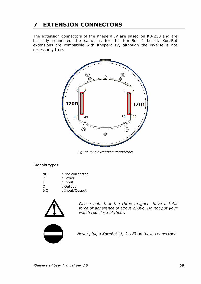
Khepera IV User Manual ver 3.0 59
7 EXTENSION CONNECTORS
The extension connectors of the Khepera IV are based on KB-250 and are basically connected the same as for the KoreBot 2 board. KoreBot
extensions are compatible with Khepera IV, although the inverse is not necessarily true.
Figure 19 : extension connectors
Signals types
NC : Not connected
P : Power
I : Input
O : Output
I/O : Input/Output
Please note that the three magnets have a total
force of adherence of about 2700g. Do not put your watch too close of them.
Never plug a KoreBot (1, 2, LE) on these connectors.
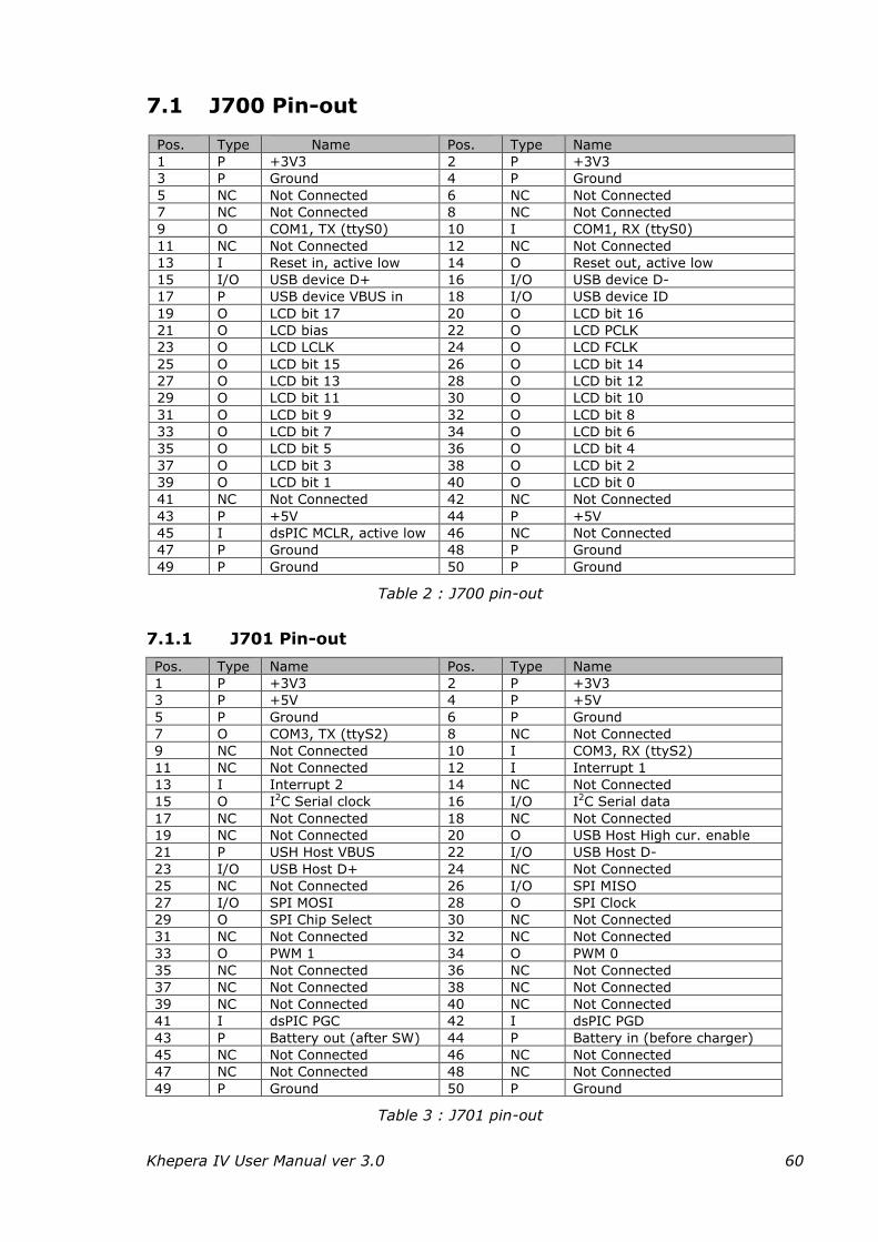
Khepera IV User Manual ver 3.0 60
7.1 J700 Pin-out
Pos. Type Name Pos. Type Name
1 P +3V3 2 P +3V3
3 P Ground 4 P Ground
5 NC Not Connected 6 NC Not Connected
7 NC Not Connected 8 NC Not Connected
9 O COM1, TX (ttyS0) 10 I COM1, RX (ttyS0)
11 NC Not Connected 12 NC Not Connected
13 I Reset in, active low 14 O Reset out, active low
15 I/O USB device D+ 16 I/O USB device D-
17 P USB device VBUS in 18 I/O USB device ID
19 O LCD bit 17 20 O LCD bit 16
21 O LCD bias 22 O LCD PCLK
23 O LCD LCLK 24 O LCD FCLK
25 O LCD bit 15 26 O LCD bit 14
27 O LCD bit 13 28 O LCD bit 12
29 O LCD bit 11 30 O LCD bit 10
31 O LCD bit 9 32 O LCD bit 8
33 O LCD bit 7 34 O LCD bit 6
35 O LCD bit 5 36 O LCD bit 4
37 O LCD bit 3 38 O LCD bit 2
39 O LCD bit 1 40 O LCD bit 0
41 NC Not Connected 42 NC Not Connected
43 P +5V 44 P +5V
45 I dsPIC MCLR, active low 46 NC Not Connected
47 P Ground 48 P Ground
49 P Ground 50 P Ground
Table 2 : J700 pin-out
7.1.1 J701 Pin-out
Pos. Type Name Pos. Type Name
1 P +3V3 2 P +3V3
3 P +5V 4 P +5V
5 P Ground 6 P Ground
7 O COM3, TX (ttyS2) 8 NC Not Connected
9 NC Not Connected 10 I COM3, RX (ttyS2)
11 NC Not Connected 12 I Interrupt 1
13 I Interrupt 2 14 NC Not Connected
15 O I2C Serial clock 16 I/O I2C Serial data
17 NC Not Connected 18 NC Not Connected
19 NC Not Connected 20 O USB Host High cur. enable
21 P USH Host VBUS 22 I/O USB Host D-
23 I/O USB Host D+ 24 NC Not Connected
25 NC Not Connected 26 I/O SPI MISO
27 I/O SPI MOSI 28 O SPI Clock
29 O SPI Chip Select 30 NC Not Connected
31 NC Not Connected 32 NC Not Connected
33 O PWM 1 34 O PWM 0
35 NC Not Connected 36 NC Not Connected
37 NC Not Connected 38 NC Not Connected
39 NC Not Connected 40 NC Not Connected
41 I dsPIC PGC 42 I dsPIC PGD
43 P Battery out (after SW) 44 P Battery in (before charger)
45 NC Not Connected 46 NC Not Connected
47 NC Not Connected 48 NC Not Connected
49 P Ground 50 P Ground
Table 3 : J701 pin-out
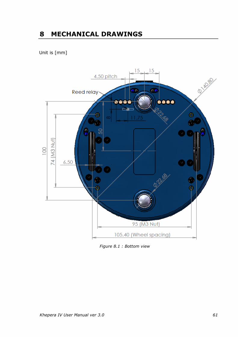
Khepera IV User Manual ver 3.0 61
8 MECHANICAL DRAWINGS
Unit is [mm]
Figure 8.1 : Bottom view
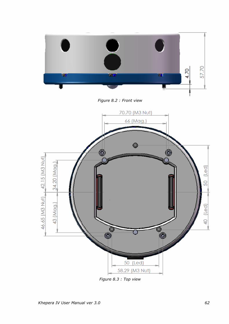
Khepera IV User Manual ver 3.0 62
Figure 8.2 : Front view
Figure 8.3 : Top view
Khepera IV User Manual ver 3.0 63
9 ANNEXES
9.1 Using Bluetooth
The following explanation will be for the Bluetooth on Linux. For Windows with Bluetooth, you can use Teraterm (http://ttssh2.sourceforge.jp) or Realterm (http://realterm.sourceforge.net, better if the com port number is
high) and jump to 3)-5) then 8).
1) Install the Linux package lrzsz containing communications programs. If your Linux distribution is Ubuntu:
sudo apt-get install lrzsz
2) On the Linux computer, run the emulation terminal Minicom:
sudo minicom
If Minicom is not installed you have to install this package. For Linux
Distribution “Ubuntu”, the command is:
sudo apt-get install minicom
Install blueman, a Bluetooth manager for Linux:
sudo apt-get install blueman
3) Switch the robot on.
4) Go to the Bluetooth configuration of your computer and search for a
new device (with blueman). The robot will appear as khepera4-ABCD, where ABCD is the serial number. Pair the robot with the access key:
0000 (four zeros). With blueman, right click on the paired khepera4-ABCD, choose "Connect to: Serial Port".
If the Khepera4 cannot be found, verify that the line below is not commented in
the file /lib/systemd/scripts/bluetooth-auto: rfcomm -r watch 0 1 /sbin/getty -w -L rfcomm0 115200 vt100 &
Then run the command: systemctl restart bluetooth-auto
5) Run minicom with the command: sudo minicom -o
6) Set its parameters with the sub-menu “Serial port setup” of the menu [configuration] (keys Ctrl-a + o) as described in Figure 9.1. Press
RETURN key to validate each time.
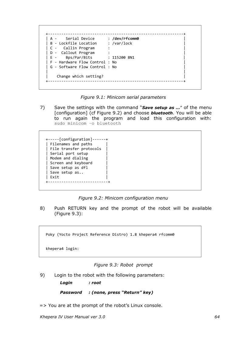
Khepera IV User Manual ver 3.0 64
+-------------------------------------------------------------+ | A - Serial Device : /dev/rfcomm0 | | B - Lockfile Location : /var/lock | | C - Callin Program : | | D - Callout Program : | | E - Bps/Par/Bits : 115200 8N1 | | F - Hardware Flow Control : No | | G - Software Flow Control : No | | | | Change which setting? | +-------------------------------------------------------------+
Figure 9.1: Minicom serial parameters
7) Save the settings with the command “Save setup as …” of the menu [configuration] (cf Figure 9.2) and choose bluetooth. You will be able
to run again the program and load this configuration with: sudo minicom –o bluetooth
+-----[configuration]------+ | Filenames and paths | | File transfer protocols | | Serial port setup | | Modem and dialing | | Screen and keyboard | | Save setup as dfl | | Save setup as.. | | Exit | +---------------------------+
Figure 9.2: Minicom configuration menu
8) Push RETURN key and the prompt of the robot will be available
(Figure 9.3):
Poky (Yocto Project Reference Distro) 1.8 khepera4 rfcomm0 khepera4 login:
Figure 9.3: Robot prompt
9) Login to the robot with the following parameters:
Login : root
Password : (none, press “Return” key)
=> You are at the prompt of the robot’s Linux console.
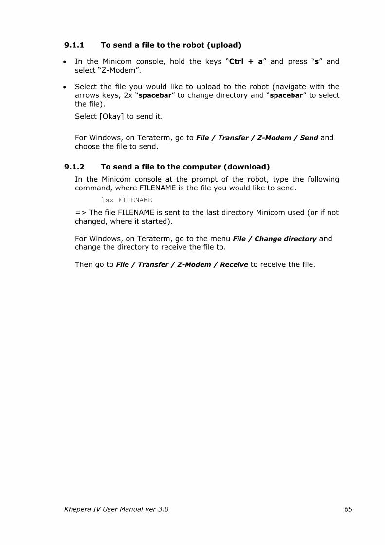
Khepera IV User Manual ver 3.0 65
9.1.1 To send a file to the robot (upload)
In the Minicom console, hold the keys “Ctrl + a” and press “s” and select “Z-Modem”.
Select the file you would like to upload to the robot (navigate with the arrows keys, 2x “spacebar” to change directory and “spacebar” to select
the file).
Select [Okay] to send it.
For Windows, on Teraterm, go to File / Transfer / Z-Modem / Send and choose the file to send.
9.1.2 To send a file to the computer (download)
In the Minicom console at the prompt of the robot, type the following
command, where FILENAME is the file you would like to send.
lsz FILENAME
=> The file FILENAME is sent to the last directory Minicom used (or if not changed, where it started).
For Windows, on Teraterm, go to the menu File / Change directory and change the directory to receive the file to.
Then go to File / Transfer / Z-Modem / Receive to receive the file.
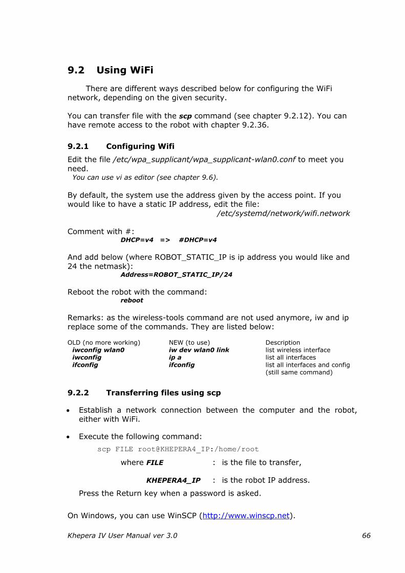
Khepera IV User Manual ver 3.0 66
9.2 Using WiFi
There are different ways described below for configuring the WiFi network, depending on the given security.
You can transfer file with the scp command (see chapter 9.2.12). You can have remote access to the robot with chapter 9.2.36.
9.2.1 Configuring Wifi
Edit the file /etc/wpa_supplicant/wpa_supplicant-wlan0.conf to meet you
need. You can use vi as editor (see chapter 9.6).
By default, the system use the address given by the access point. If you would like to have a static IP address, edit the file:
/etc/systemd/network/wifi.network Comment with #:
DHCP=v4 => #DHCP=v4
And add below (where ROBOT_STATIC_IP is ip address you would like and
24 the netmask): Address=ROBOT_STATIC_IP/24
Reboot the robot with the command: reboot
Remarks: as the wireless-tools command are not used anymore, iw and ip replace some of the commands. They are listed below: OLD (no more working) NEW (to use) Description
iwconfig wlan0 iw dev wlan0 link list wireless interface iwconfig ip a list all interfaces ifconfig ifconfig list all interfaces and config
(still same command)
9.2.2 Transferring files using scp
Establish a network connection between the computer and the robot, either with WiFi.
Execute the following command:
scp FILE root@KHEPERA4_IP:/home/root
where FILE : is the file to transfer,
KHEPERA4_IP : is the robot IP address.
Press the Return key when a password is asked.
On Windows, you can use WinSCP (http://www.winscp.net).
Khepera IV User Manual ver 3.0 67
9.2.3 Remote access
You can have remote access to the robot console while using WiFi
Establish a connection between the robot and the computer with one of
the connections WiFi method described in the chapters above.
In a console of the computer, launch the ssh command, where
KHEPERA4_IP_ADDRESS is the network address of your robot:
ssh root@KHEPERA4_IP_ADDRESS
Accept the host authenticity by answering yes in pushing Return key.
=> root@khepera4:~# appears; you are logged in.
Khepera IV User Manual ver 3.0 68
9.2.4 NFS configuration
The first service to set up should be transparent file sharing using NFS. Most Linux distributions include NFS support by default, and the robot system
is ready to be connected. The directory to be shared between the computer and the board must be declared to the NFS service in the /etc/exports
configuration file. Please refer to NFS documentation (or man exports) for a detailed syntax description. Basically, the following line should be added to
the file /etc/exports on the computer:
/mnt/nfsarm KHEPERA4_IP/255.255.255.0(rw,no_root_squash,sync)
And make this folder on the computer:
mkdir /mnt/nfsarm
Restart nfs server on the computer: sudo service nfs-kernel-server restart
The next step is to mount the shared directory to the robot file system.
Mounting a local hard drive partition or a network directory is exactly the same from the user point of view, the mount commands should be on the robot, where COMPUTER_IP, is the IP address of the computer which the
robot will be connected:
mkdir /mnt/nfs
mount -t nfs -o nolock COMPUTER_IP:/mnt/nfsarm /mnt/nfs
If the NFS service is not started on the PC, the mount command will issue the following message:
mount: RPC: Unable to receive; errno = Connection refused
NFS: mount program did not respond!
mount: nfsmount failed: Bad file descriptor
The NFS service is usually started using a startup script for which location and name depend on you distribution (for Ubuntu example
https://help.ubuntu.com/community/SettingUpNFSHowTo).
Documentation for the distribution should detail the method to start and stop services.
Caution: For the NFS service to work properly, the portmap service should be started as well and if a firewall is active on the host machine, it should be
configured to allow the NFS port access from the robot. Once the directory is successfully mounted, it can be accessed from the board
exactly as if it was a local directory. Files on the PC can be read or written, new files can be created, and programs can be executed, as long as they are
ARM executables. If required, the shared directory can be unmounted using the command:
umount myMountPoint
Khepera IV User Manual ver 3.0 69
9.3 Using the camera module
The driver of the camera (mt9v032.so) is loaded by default on start-
up.
9.3.1 Taking images
With the v4l2grab program, you can take snapshots pictures with the camera. The first time you have to set the pipes and formats by running:
media-pipes.sh
media-formats.sh 752 480
And take one image 'image.jpg' at 85% jpge quality with this command:
v4l2grab -d /dev/video6 -o image.jpg -W 752 -H 480 -q 85 -I -1
The message "[ xxxx.xxxxxx] isp_video_enum_format: invalid index (1)" is normal.
where: image.jpg is the output image file in JPEG format
752 is the width of the image in pixel (max)
480 is the height of the image in pixel (max)
85 is the quality jpg compression in %
/dev/video6 is the video device
-I -1 image framerate (currently not working)
Khepera IV User Manual ver 3.0 70
9.3.2 Video Streaming
You need a computer with vlc Gstreamer installed (not working on Virtualbox).For Ubuntu, install Gstreamer with:
sudo apt-get install gstreamer0.1*
Firstly, set a network connection as explained in chapters 9.2.
Then set the pipes and image size (only one time per session): media-pipes.sh media-formats.sh 192 120
9.3.2.1 jpeg mode
On the robot run (in one line): gst-launch v4l2src device=/dev/video6 ! autoconvert ! jpegenc quality=70 ! multipartmux ! tcpserversink port=5000
On the computer, run (where ROBOT_IP is the ip address of your
robot): vlc tcp://ROBOT_IP:5000
Or for Windows VLC : Menu, Open Network stream and use tcp://ROBOT_IP:5000 as URL
Or (not working on Virtualbox): gst-launch tcpclientsrc host=ROBOT_IP port=5000 ! multipartdemux ! jpegdec ! xvimagesink
9.3.2.2 raw mode (not working on Virtualbox)
On the robot run (in one line, where COMPUTER_IP is the ip address of
your computer): gst-launch -v v4l2src device=/dev/video6 ! rtpvrawpay ! udpsink host=COMPUTER_IP port=5000
On the computer run (in one line): gst-launch -v udpsrc port=5000 caps="application/x-rtp, media=(string)video, clock-rate=(int)90000, encoding-name=(string)RAW, sampling=(string)YCbCr-
4:2:2, depth=(string)8, width=(string)192, height=(string)120, colorimetry=(string)SMPTE240M, payload=(int)96" ! rtpvrawdepay ! xvimagesink
You can have more information there: https://github.com/gumstix/yocto-manifest/wiki/Gstreamer-and-Caspa
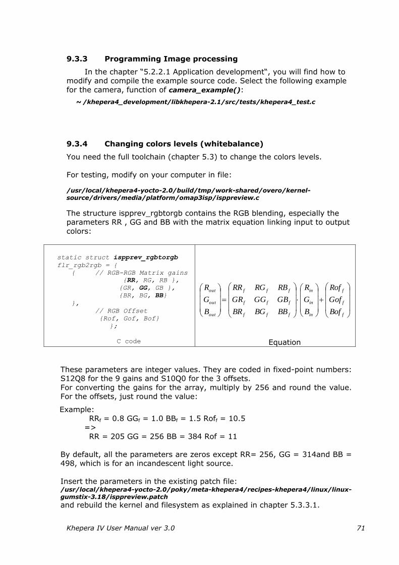
Khepera IV User Manual ver 3.0 71
9.3.3 Programming Image processing
In the chapter “5.2.2.1 Application development“, you will find how to modify and compile the example source code. Select the following example
for the camera, function of camera_example():
~ /khepera4_development/libkhepera-2.1/src/tests/khepera4_test.c
9.3.4 Changing colors levels (whitebalance)
You need the full toolchain (chapter 5.3) to change the colors levels.
For testing, modify on your computer in file:
/usr/local/khepera4-yocto-2.0/build/tmp/work-shared/overo/kernel-source/drivers/media/platform/omap3isp/isppreview.c
The structure ispprev_rgbtorgb contains the RGB blending, especially the parameters RR , GG and BB with the matrix equation linking input to output
colors:
static struct ispprev_rgbtorgb
flr_rgb2rgb = {
{ // RGB-RGB Matrix gains
{RR, RG, RB },
{GR, GG, GB },
{BR, BG, BB}
},
// RGB Offset
{Rof, Gof, Bof}
};
C code
f
f
f
in
in
in
fff
fff
fff
out
out
out
Bof
Gof
Rof
B
G
R
BBBGBR
GBGGGR
RBRGRR
B
G
R
Equation
These parameters are integer values. They are coded in fixed-point numbers: S12Q8 for the 9 gains and S10Q0 for the 3 offsets.
For converting the gains for the array, multiply by 256 and round the value. For the offsets, just round the value:
Example: RRf = 0.8 GGf = 1.0 BBf = 1.5 Roff = 10.5
=>
RR = 205 GG = 256 BB = 384 Rof = 11
By default, all the parameters are zeros except RR= 256, GG = 314and BB = 498, which is for an incandescent light source.
Insert the parameters in the existing patch file: /usr/local/khepera4-yocto-2.0/poky/meta-khepera4/recipes-khepera4/linux/linux-gumstix-3.18/isppreview.patch and rebuild the kernel and filesystem as explained in chapter 5.3.3.1.
Khepera IV User Manual ver 3.0 72
9.4 Using microphone and speaker
Playing:
You must switch ON the speaker with the commands:
echo 64 >/sys/class/gpio/export
echo out >/sys/class/gpio/gpio64/direction
echo 1 >/sys/class/gpio/gpio64/value
You can play PCM WAV files with aplay and the syntax:
aplay FILE.wav
and MPEG audio files with madplay and the syntax:
madplay FILENAME –o cdda:- | aplay –f cdr
You can then switch the speakers OFF with:
echo 0 >/sys/class/gpio/gpio64/value
echo 64 >/sys/class/gpio/unexport
Recording:
You can record PCM WAV with arecord and the syntax:
arecord –f cd FILENAME.wav
The –f cd parameter sets the recording in stereo mode in CD quality. See
with the command arecord –h for all the parameters and help.
Controlling volume:
You can modify the playback volume by launching the volume mixer with
the command:
alsamixer
You change channel with the keyboard left and right arrows and volume with the up/down arrows. The channels are for speakers of the robot:
"Dac2 Analog" for standard control
"Dac2 Digital Coarse" for rough control
"Dac2 Fine Coarse" for fine control
You can change left and right with while a channel above is selected with:
Q and Z for left
W and X for both
E and C for right
And mute:
left with < key
Khepera IV User Manual ver 3.0 73
right with > key
Pushing h will get you more help.
For modifying the record volume, push the Tab key while in alsamixer.
You change channel with the keyboard left and right arrows and volume with the up/down arrows. The channel is for the robot:
"Analog Right Sub Mic" for mute settings of the micro
By default the record channels are muted. While a channel is selected,
pushing spacebar will toggle it. You can change left and right while the "Analog" is selected with:
Q and Z for left
W and X for both
E and C for right
Programming playback and record:
In the chapter "5.2.2.1 Application development", you will find how to modify and compile the examples source code. Select the following example
for the sound, function of test_sound():
~ /khepera4_development/libkhepera-2.1/src/tests/khepera4_test.c
Remark: don't forget to mute the microphones when you play and also
mute the speakers when you record otherwise noise will appear!
Khepera IV User Manual ver 3.0 74
9.5 Development with a virtual machine
You can install the development tools on a virtual machine if you don't
have access to a Linux machine.
You can even find a virtual machine image already configured with the development tools on the DVD or there:
http://ftp.k-team.com/KheperaIV/software/virtual_machine/
- for the light tools (~3.3 GB):
Ubuntu_LTS_Khepera4_Yocto-y.ova
Download and install VirtualBox, version 5.0.20 or newer for your computer from:
https://www.virtualbox.org/wiki/Downloads
If you choose a more recent version, you will have to reinstall the Guest Additions after having imported the image; see VirtualBox user manual
(also, if you update Ubuntu, you will have to reinstall the Guest Additions).
Download and install also the VirtualBox 5.0.20 Oracle VM
VirtualBox Extension Pack from the webpage above.
Import on of the image file above with "File" menu, "Import Appliance"
in the VirtualBox Manager.
This will take some time and hard disk space (~8 GB for tools).
Create the directory C:\virtual_machine_shared on your computer. This
will be the shared directory for transferring data between the virtual machine and your host computer. It corresponds to the directory
/media/sf_virtual_machine_shared of the virtual machine.
Start the virtual machine with your imported image:
Its login is:
username: user password: root2016
The development tools are already installed. The development folder khepera4_development is in /home/user/khepera4_ development
Eclipse development program is already installed and configured. You
can start to use it as described in chapter 5.2.2.2 from point 15.
You may need to update the toolchain. Remove the older one and follow
instructions in chapter 5.2.1 or 5.3.2 depending if this is the light or full toolchain.
Khepera IV User Manual ver 3.0 75
Stopping the virtual machine:
When going to the menu "Machine" and "Close, you will have 3 choices:
"Save the machine state": saves the current state, which will be reloaded next time you restart it.
“Send the shutdown signal", or press the shutdown button into the machine: power off the machine and save only the work done.
"Power off the machine": WARNING: it doesn't save anything; any work done will be discarded!
Serial port sharing:
You may configure your virtual machine to share the serial port to connect
to the robot (for using Bluetooth …).
Power off your virtual machine.
Select your machine image and press "Settings" button.
Go to "Serial Ports" settings;
On the tab "Port 1", enable the checkbox "Enable Serial Port" and
choose:
Port Number: COM1 ( => this will be the Linux serial port /dev/ttyS0)
Port Mode: Host Device
Port/File Path: COM1 if you have a standard serial port and using COM1. Or adapt to your computer serial port or
Bluetooth emulated serial port.
Khepera IV User Manual ver 3.0 76
9.6 Using vi text file editor
You can use the installed vi text file editor to modify files directly on the
robot.
Launch it with: vi FILENAME where FILENAME is the filename with path you would like to edit.
Here below are some of the basic commands:
i enters in write mode for adding text. You will see
the I indicating this mode at the last line of the console: I /tmp/essai 1/1 100%
a enters in write mode for adding text. You will see
the I indicating this mode at the last line of the
console: I /tmp/essai 1/1 100% ESC to go back in command mode, push ESC key x delete character on cursor d d delete current line arrow keys move around text
ESC : set number to display line number ESC : w q ! to save and quit ESC : q ! to quit without saving
You will find more commands here:
http://www.tutorialspoint.com/unix/unix-vi-editor.htm
Khepera IV User Manual ver 3.0 77
10 WARRANTY
K-TEAM warrants that the Product is free from defects in materials and
workmanship and in conformity with the respective specifications of the product for the minimum legal duration, respectively two years from the date of delivery.
Upon discovery of a defect in materials, workmanship or failure to meet
the specifications in the Product during the aforementioned period, Customer must request help on K-TEAM Internet forum on www.k-team.com/forum/ by detailing:
The type of Product used (package, version). The expansion modules.
The programming environment of the Product (standard, version, OS).
The standard use of Product before the appearance of the
problem. The description of the problem.
If no answers have been received within two working days, Customer
can contact K-TEAM support by phone or by electronic mail with the full
reference of its order and Product serial number.
K-TEAM shall then, at K-TEAM's sole discretion, either repair such Product or replace it with the equivalent product without charging any technical labour fee and repair parts cost to Customer, on the condition that
Customer brings such Product to K-TEAM within the period mentioned before. In case of repair or replacement, K-TEAM may own all the parts
removed from the defective Product. K-TEAM may use new and/or reconditioned parts made by various manufacturers in performing warranty repairs and replacement of the Product. Even if K-TEAM repairs or replaces
the Product, its original warranty term is not extended.
This limited warranty is invalid if the factory-applied serial number has been altered or removed from the Product.
This limited warranty covers only the hardware and software components contained in the Product. It does not cover technical assistance
for hardware or software usage and it does not cover any software products contained in the Product. K-TEAM excludes all warranties expressed or
implied in respect of any additional software provided with Product and any such software is provided "AS IS" unless expressly provided for in any enclosed software limited warranty. Please refer to the End User License
Agreements included with the Product for your rights with regard to the licensor or supplier of the software parts of the Product and the parties'
respective obligations with respect to the software. This limited warranty is non-transferable.
It is likely that the contents of Customer's flash memory will be lost or
reformatted in the course of the service and K-TEAM will not be responsible
Khepera IV User Manual ver 3.0 78
for any damage to or loss of any programs, data or other information stored on any media or any part of the Product serviced hereunder or damage or loss arising from the Product not being available for use before, during or
after the period of service provided or any indirect or consequential damages resulting therefore.
IF DURING THE REPAIR OF THE PRODUCT THE CONTENTS OF THE
FLASH MEMORY ARE ALTERED, DELETED, OR IN ANY WAY MODIFIED, K-TEAM IS NOT RESPONSIBLE WHATEVER. CUSTOMER'S PRODUCT WILL BE RETURNED TO CUSTOMER CONFIGURED AS ORIGINALLY PURCHASED
(SUBJECT TO AVAILABILITY OF SOFTWARE).
Be sure to remove all third parties' hardware, software, features, parts, options, alterations, and attachments not warranted by K-TEAM prior to Product service. K-TEAM is not responsible for any loss or damage to these
items.
This warranty is limited as set out herein and does not cover, any consumable items (such as batteries) supplied with the Product; any accessory products which is not contained in the Product; cosmetic
damages; damage or loss to any software programs, data, or removable storage media; or damage due to (1) acts of God, accident, misuse, abuse,
negligence, commercial use or modifications of the Product; (2) improper operation or maintenance of the Product; (3) connection to improper voltage supply; or (4) attempted repair by any party other than a K-TEAM
authorized robot service facility.
This limited warranty does not apply when the malfunction results from the use of the Product in conjunction with any accessories, products or ancillary or peripheral equipment, or where it is determined by K-Team that
there is no fault with the Product itself.
K-TEAM EXPRESSLY DISCLAIMS ALL OTHER WARRANTIES THAN STATED HEREINBEFORE, EXPRESSED OR IMPLIED, INCLUDING WITHOUT LIMITATION IMPLIED WARRANTIES OF MERCHANTABILITY AND FITNESS
FOR A PARTICULAR PURPOSE TO THE FULLEST EXTENT PERMITTED BY LAW.
Limitation of Liability: IN NO EVENT SHALL EITHER PARTY BE LIABLE
TO THE OTHER FOR ANY INDIRECT, SPECIAL, INCIDENTAL OR
CONSEQUENTIAL DAMAGES RESULTING FROM PERFORMANCE OR FAILURE TO PERFORM UNDER THE CONTRACT, OR FROM THE FURNISHING,
PERFORMANCE OR USE OF ANY GOODS OR SERVICE SOLD OR PROVIDED PURSUANT HERETO, WHETHER DUE TO A BREACH OF CONTRACT, BREACH
OF WARRANTY, NEGLIGENCE, OR OTHERWISE. SAVE THAT NOTHING HEREIN SHALL LIMIT EITHER PARTY'S LIABILITY FOR DEATH OR PERSONAL INJURY ARISING FROM ITS NEGLIGENCE, NEITHER PARTY SHALL HAVE ANY
LIABILITY TO THE OTHER FOR INDIRECT OR PUNITIVE DAMAGES OR FOR ANY CLAIM BY ANY THIRD PARTY EXCEPT AS EXPRESSLY PROVIDED
HEREIN.

K-Team S.A. Z.I. Les Plans-Praz 28
1337 Vallorbe Switzerland