Khalid Ahmed Heavy Oil Group - Kuwait Oil Company Knowledge Shared/Heavy Oil/Perforation...
24
Click to edit Master title style www.kockw.com Perforation Strategy for Sand Management in Lower Fars Unconsolidated Formation Khalid Ahmed Heavy Oil Group
Transcript of Khalid Ahmed Heavy Oil Group - Kuwait Oil Company Knowledge Shared/Heavy Oil/Perforation...
Click to edit Master title style
www.kockw.com
Perforation Strategy for Sand Management
in
Lower Fars Unconsolidated Formation
Khalid Ahmed
Heavy Oil Group
www.kockw.com
Outline
Concept Statement
Heavy Oil Fields in North Kuwait
Lower Fars Formation and its Rock Mechanics
Sand Production Potential
Perforation Strategy- Pre-Lab Test
Lab Test for Optimum Perforator Selection
Conclusions, Recommendations and Way Forward

www.kockw.com
Concept Statement
Perforation Strategy has to be formation specific
Formation rock mechanics alongwith stress profile dictate perforation type (DP/ BH), spf and phase angle
For steam injector and producer, perforation strategy is essentially different
As soft formation essentially produces sand, critical drawdown pressure information shall help its containment
Sand containment through perforation strategy shall ultimately help in production enhancement by eliminating/ minimising sand control equipment

www.kockw.com
Outline
Concept Statement
Heavy Oil Fields in North Kuwait
Lower Fars Formation and its Rock Mechanics
Sand Production Potential
Perforation Strategy- Pre-Lab Test
Lab Test for Optimum Perforator Selection
Conclusions, Recommendations and Way Forward

www.kockw.com
Heavy Oil Fields in North Kuwait
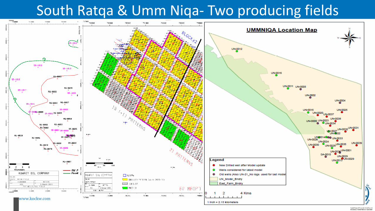
All major Fields of North Kuwait-South Ratqa, Mutriba, Raudhatain, Sabriyah, Bahrah and Umm Niqa have dedicated shallow-depth wells drilled in Lower Fars
MUTRIBA
SOUTH RATQA
RAUDHATAIN
SABRIYAH
BAHRAH
UMM NIQA
www.kockw.com
South Ratqa & Umm Niqa- Two producing fields

www.kockw.com
Outline
Concept Statement
Heavy Oil Fields in North Kuwait
Lower Fars Formation and its Rock Mechanics
Sand Production Potential
Perforation Strategy- Pre-Lab Test
Lab Test for Optimum Perforator Selection
Conclusions, Recommendations and Way Forward

www.kockw.com
Lower Fars FormationStacked Channel Sand
- Lower Fars is a shallow depth unconsolidated multi-stacked sand-shale sequence
- Porosity is in excess of 30 pu andpermeability for cleaner part is above4 to 5 Dacy
- Oil viscosities vary both laterally andvertically
Weak Rock
- Lower Fars is a weak, friable rock- Unconfined Compressive Strength
(UCS) is very low -225 psi for F1A and 350 psi for F1B
- Friction Angle is 25 deg for F1A and 27 deg for F1B
Grain Size Distribution
- Grain Size Analysis is a key input for Sanding risk analysis
- Finer particles have greater sanding potential
- F1A is relatively coarserthan F1B

www.kockw.com
Lower Fars rock shows Plasticity• 7” casing is cemented with 15.8 ppg
thermal cement- without any loss
• ELOT and Minifrac suggest higher FracGradient (≥ 0.65 psi/ft), with Leak-off pressure in excess of 500 psi – against formation pressure of 230 – 250 psi
• Total Clay content in sand is ≤ 5%, majority being Illite- Smectite. Shale hydration can be controlled with higher % of KCl
The rock is friable.Under stress it behaves more plastic
than elastic
www.kockw.com
Outline
Concept Statement
Heavy Oil Fields in North Kuwait
Lower Fars Formation and its Rock Mechanics
Sand Production Potential
Perforation Strategy- Pre-Lab Test
Lab Test for Optimum Perforator Selection
Conclusions, Recommendations and Way Forward

www.kockw.com
Sand Production Potential
Factors affecting sand production
- Rock Strength (UCS)- Pore Pressure and Depletion- In-Situ Stresses- Grain-size Distribution- Perforation Size and Orientation
Critical Drawdown Pressure
- Critical Drawdown Pressure defines “weak“ zones to start producing sand
- Typically, Perforation creates cylindrical cavity
- Expt. shows a spherical cavity to be more stable than cylindrical
- Drawdown determines stable shape of cavity, hence sand production
Sand-free Production
- It is possible to have sand free production in a well
- If there is no “Weak” zone interms of Critical DrawdownPressure
Green zones are sand freeRed zones produce sand
Co = Unconfined compressive strengthPc
d = Critical Drawdown pressure
Reference: Petroleum Related Rock MechanicsErling Fjar, R.M. Holt, A.M. Raaen, R. Risnes, P. Horsrud

www.kockw.com
Outline
Concept Statement
Heavy Oil Fields in North Kuwait
Lower Fars Formation and its Rock Mechanics
Sand Production Potential
Perforation Strategy- Pre-Lab Test
Lab Test for Optimum Perforator Selection
Conclusions, Recommendations and Way Forward
www.kockw.com
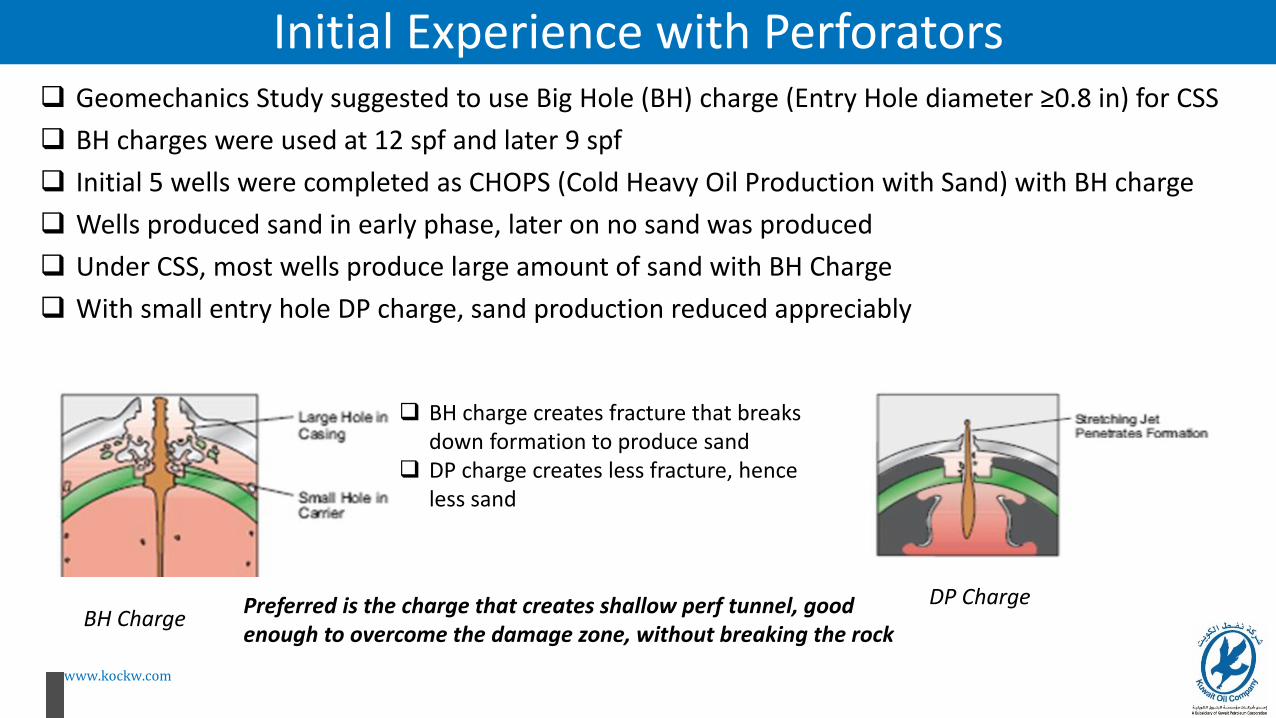
Initial Experience with Perforators Geomechanics Study suggested to use Big Hole (BH) charge (Entry Hole diameter ≥0.8 in) for CSS
BH charges were used at 12 spf and later 9 spf
Initial 5 wells were completed as CHOPS (Cold Heavy Oil Production with Sand) with BH charge
Wells produced sand in early phase, later on no sand was produced
Under CSS, most wells produce large amount of sand with BH Charge
With small entry hole DP charge, sand production reduced appreciably
BH ChargeDP Charge
BH charge creates fracture that breaks down formation to produce sand
DP charge creates less fracture, hence less sand
Preferred is the charge that creates shallow perf tunnel, good enough to overcome the damage zone, without breaking the rock

www.kockw.com
Limited Entry Perforation (LEP)- Analytical Approach For steam injection operations, G P Small suggested an analytical approach of LEP
LEP is based on the principle of critical steam flow through an orifice
At critical flow condition, steam is injected at sonic velocity
Under this condition, for a given hole diameter and bottom hole injection pressure :
– Flow is choked, thereby limiting maximum rate of injected steam per perforation
– No single perforation can act as a thief zone
Steam-Injection Profile Control using Limited Entry Perforations (SPE- 13607), 1985;
also Production Engineering September 1986
is = 4.07 FdD A p0.97 fs-0.5
is = steam injection rate per perforation at critical flow, B/D steam
FdD = dimensionless discharge factor, usually ranges between
0.6 and 0.7
A = perforation area, in.2
p = bottomhole injection pressure, psia
fs = steam quality, mass fraction
FdD = 0.65
A = various, calculated from perforation hole
diameters from different gun systems
p = 450 psia
fs = 60%

www.kockw.com
Calculation with planned Gun SystemGun System
RP19B/43 Sec-1: Hole dia in 7" casing
is,, Flow rate per perf at critical flow
(B/D)
Max number of perforations allowed
for critical flow
Shot density over 150-ft interval
Total flow area over 150-ft interval (in2)
INJE
CTO
R
WEL
LS
2" DP 7g 0.24 58 17 1 shot/9 ft 0.774 1/2" DP 23g 0.3 90 11 1shot/14 ft 0.784 1/2" DP 39g 0.35 123 8 1shot/19 ft 0.774 1/2" DP 39g 0.4 161 6 1shot/25 ft 0.75
PR
OD
UC
ER
WEL
LS
4 1/2" BH 23g 0.65 12 SPF 5974 1/2" BH 28g 0.85 12 SPF 1021
4 1/2" BH 28g 0.96 12 SPF 1303
For commercial phase, it was decided not to perforate the full 150ft, rather only F1B is to be perforated, which is max
35ft per well

www.kockw.com
Numerical Analysis and Simulation Numerical Analysis (Halliburton’s PerfPro) was
used to estimate Productivity index
Simulation (Halliburton’s PulsFrac) was used to predict formation Breakdown around the perforation tunnel and to optimize number of shots to avoid formation breakdown

www.kockw.com
Analysis and RecommendationsGun Type spf EHD Formation breakdown (up to
10” hole)Formation breakdown (up to 15” hole)
4 ½” 5 spf SDP 5 0.37” No No
4 ½” 12 spf DP 12 0.38” Yes (Frac Length: 16.72 ft, fracwidth: 0.04” , conductivity: 55 md-ft)
No
4 ½” 12 spf BH 12 0.8” Yes (Frac Length: 12.6 ft, fracwidth: 0.04” , conductivity: 72 md-ft)
Not recommended as only 1” penetration inside formation
9 spf DP for hole size ≥15-in 9 spf BH for hole size ≤10-in If more production is desired and sand production can be tolerated, then 12 spf BH

www.kockw.com
Outline
Concept Statement
Heavy Oil Fields in North Kuwait
Lower Fars Formation and its Rock Mechanics
Sand Production Potential
Perforation Strategy- Pre-Lab Test
Lab Test for Optimum Perforator Selection
Conclusions, Recommendations and Way Forward
www.kockw.com
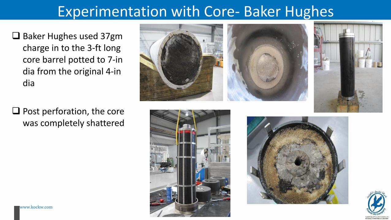
Experimentation with Core- Baker Hughes
Baker Hughes used 37gm charge in to the 3-ft long core barrel potted to 7-in dia from the original 4-in dia
Post perforation, the core was completely shattered

www.kockw.com
Experimentation on Core - Halliburton
4”-dia 3ft long core removed carefully from aluminum tube
Removed core potted with hydrostone and low-strength Portland cement to make 7” dia Potted core encapsulated
in Viton sleeve
core was mounted in API RP 19B, Section 4 vessel confined at expected field stress
Single shots were fired on core target at
4 ½” gun sytem, 12 spf and 2” gun at 6 spf at room temp
with nominal pressure of 800 psi
and wellbore pressure of 600psi
OMS: Odourless Mineral Spirit
At a drawdown pressure of 50 psi,
crude oil in the core was displaced with
miscible OMS and both pre and post injection permeabilities were
measured
Reference: WHOC16-606

www.kockw.com
Observations from the Experiment on Core Samples
3-ft Core Sample CT Scan Test-3 Perforation Event Pressure Plot
- 17.5 g DP charge- Depth of Penetration: 29 in- Entry Hole Dia: 0.35 in
Pressure-Temperature-Flow
Permeability Index= 1400 mD in production at a production ratio of 0.8 against baseline perm=1703mD
- 7 g DP charge After displacing with hot water
- 7 g DP charge- Depth of Penetration: 15.88 in- Entry Hole Dia: 0.19 in
Injection Production
Flow direction was reversed after 50 min of injection @100mL/min (≥3 pore volume) to
Production
www.kockw.com
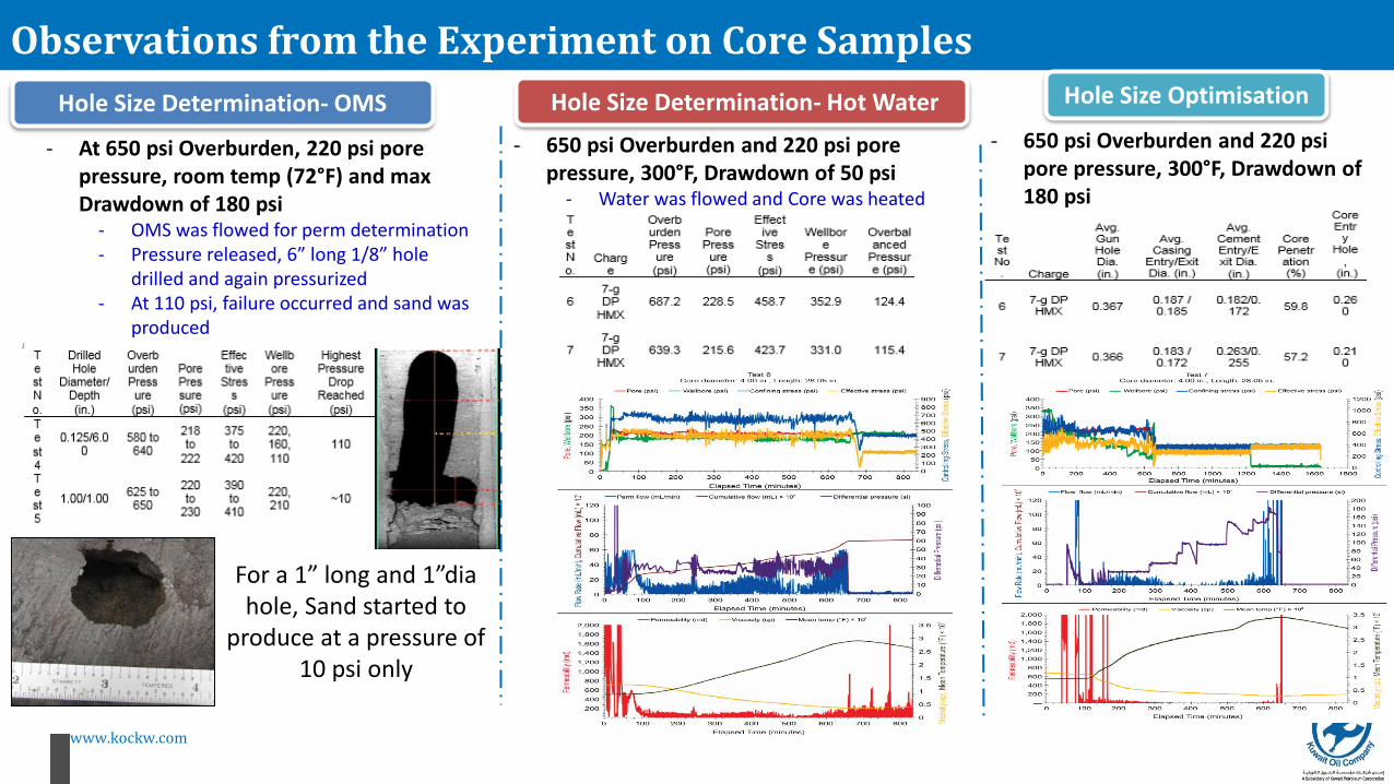
Observations from the Experiment on Core Samples
Hole Size Determination- OMS Hole Size Determination- Hot Water
- At 650 psi Overburden, 220 psi pore pressure, room temp (72°F) and max Drawdown of 180 psi
- OMS was flowed for perm determination- Pressure released, 6” long 1/8” hole
drilled and again pressurized- At 110 psi, failure occurred and sand was
produced
Hole Size Optimisation
- 650 psi Overburden and 220 psi pore pressure, 300°F, Drawdown of 180 psi
- Entry Hole diameter = 0.24 in
- 650 psi Overburden and 220 psi pore pressure, 300°F, Drawdown of 50 psi
- Water was flowed and Core was heated
For a 1” long and 1”dia hole, Sand started to
produce at a pressure of 10 psi only
www.kockw.com
Outline
Concept Statement
Heavy Oil Fields in North Kuwait
Lower Fars Formation and its Rock Mechanics
Sand Production Potential
Perforation Strategy- Pre-Lab Test
Lab Test for Optimum Perforator Selection
Conclusions, Recommendations and Way Forward

www.kockw.com
Conclusions, Recommendations and Way Forward
Perforation Strategy- CSS & SF Overbalance and Drawdown Pressure
- Use 4 ½” gun DP charges at 6 spf and 60°phasing
- Entry Hole Diameter = 0.24”- Reduced sand production
Way Forward
- Under SF, Injector wells to be re-perforated with DP at 6 spf – to enhance injectivity
- Perforation is to be made with a minimum of 200 psi overbalance with water in wellbore
- No solvent to be added- Solvent can wash the crude oil off the
sand- This would reduce the cohesive strength
and resistance to sand movement
- Planned Injection rate = 1000 bcwe/d- Steam Injection pressure = 350 to 450 psi- Reservoir Pressure=230 psi- Differential Pressure= 120 to 220 psi
- Using LEP Concept, at 350 psi injection pressure for a 35ft interval, it would be at 23/35 = 0.66 spf and at 450 psi injection pressure for a 20ft interval, it would be at 18/20 = 0.9 spf
- Geomechanics Study suggests orienting perforation sub-parallel to minimum horizontal stress can enhance critical drawdown by 20 psi, reducing sand production
- Initial drawdown pressure should be 25% of expected maximum (which is 180psi)
- Just under 50 psi- This would avoid initial high-velocity
surging- Once flow is stabilized, drawdown can be
ramped up
- Under SF, Producer wells to be re-perforated with BH at 9 / 12 spf – to enhance productivity
- Entry Hole diameter = 0.8 in
- As it is difficult to orient in vertical well, shooting guns downward at 15°would reduce sanding and enhance steam contact with less disturbed formation
- Filling the void space inside the gun with Foam shall help to create Dynamic Underbalance, reducing sand production