Keysight Technologies Transition from 2G/3G to 3.9G/4G Base ...
26
Keysight Technologies Transition from 2G/3G to 3.9G/4G Base Station Receiver Conformance Test Application Note
Transcript of Keysight Technologies Transition from 2G/3G to 3.9G/4G Base ...
Keysight TechnologiesTransition from 2G/3G to 3.9G/4G Base Station Receiver Conformance Test
Application Note
Introduction
Dramatic increases in data traffic generated by the increasingly common use of internet-enabled devices, such as smartphones, is prompting rapid development of faster data throughput networks. Base transceiver stations (BTS) being used to deliver 2G and 3G services are migrating to faster data cellular formats such as HSPA+ and LTE to accommodate this evolution. The test requirements for newly emerging formats are progressively more complicated. Conformance tests are required to verify that a BTS performs as designed, while meeting radio regulations and interoperability requirements set by standards bodies such as ITU and 3GPP, as well as local governments. Understanding the purpose of the tests, as well as the definitions, and requirements defined in the standards, and selecting the right test equipment, are necessary steps in performing successful BTS conformance tests within a limited timeframe.
This application note provides information that will help you migrate from 2G/3G BTS receiver testing to 3.9G and 4G base station testing. Various receiver conformance test requirements will be explained, as will how to perform those tests using the new X-Series signal generators. Also included in this document is an overview of the challenges faced when performing 3.9G and 4G BTS conformance tests.
3
BTS receiver tests measure the BTS’s ability to receive an uplink signal from the UE (User Equipment) and to decode data correctly. The signal generator is used to provide the UE uplink signal. BER (Bit Error Rate), BLER (Block Error Rate), and throughput are commonly used as parameters for measuring receiver performance. The test signal conditions tend to be very tight to measure whether or not a receiver can receive data correctly under constraints such as very low signal power, interference in the vicinity, and/or under multipath fading conditions. BER is commonly used by 3G and prior standards as a parameter to measure and characterize receiver performance. It uses known data sequences such as PN (Pseudo-random Noise) as transmission data. BTS receivers receive data and compare it to the known PN sequence in order to measure BER.
As use of packet-based data is becoming more common and higher processing power is becoming more cost effective, error correction and retransmission schemes are starting to be used more often. Receiver performance measure-ments for 3.9G or 4G systems, such as LTE, are also changing to accommodate those technologies by using BLER or throughput as the new parametric measurement. BLER and throughput decode received data and check CRC (Cyclic Redundancy Check) codes attached to the data to see if received data is correct or not on a block by block basis. It is not necessary for a receiver to know what kind of data is being sent beforehand, as it is with BER test.
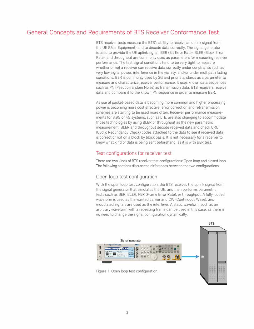
Test configurations for receiver testThere are two kinds of BTS receiver test configurations: Open loop and closed loop. The following sections discuss the differences between the two configurations.
Open loop test configurationWith the open loop test configuration, the BTS receives the uplink signal from the signal generator that simulates the UE, and then performs parametric tests such as BER, BLER, FER (Frame Error Rate), or throughput. A fully-coded waveform is used as the wanted carrier and CW (Continuous Wave), and modulated signals are used as the interferer. A static waveform such as an arbitrary waveform with a repeating frame can be used in this case, as there is no need to change the signal configuration dynamically.
General Concepts and Requirements of BTS Receiver Conformance Test
Signal generator
BTS
Rx
Figure 1. Open loop test configuration.
4
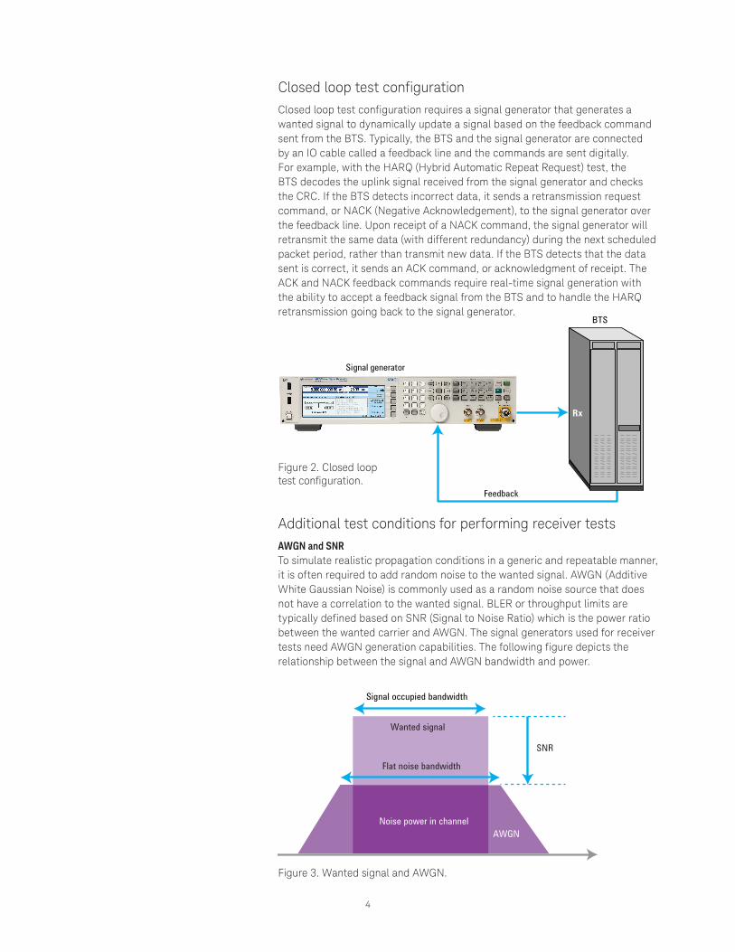
Closed loop test configurationClosed loop test configuration requires a signal generator that generates a wanted signal to dynamically update a signal based on the feedback command sent from the BTS. Typically, the BTS and the signal generator are connected by an IO cable called a feedback line and the commands are sent digitally. For example, with the HARQ (Hybrid Automatic Repeat Request) test, the BTS decodes the uplink signal received from the signal generator and checks the CRC. If the BTS detects incorrect data, it sends a retransmission request command, or NACK (Negative Acknowledgement), to the signal generator over the feedback line. Upon receipt of a NACK command, the signal generator will retransmit the same data (with different redundancy) during the next scheduled packet period, rather than transmit new data. If the BTS detects that the data sent is correct, it sends an ACK command, or acknowledgment of receipt. The ACK and NACK feedback commands require real-time signal generation with the ability to accept a feedback signal from the BTS and to handle the HARQ retransmission going back to the signal generator.
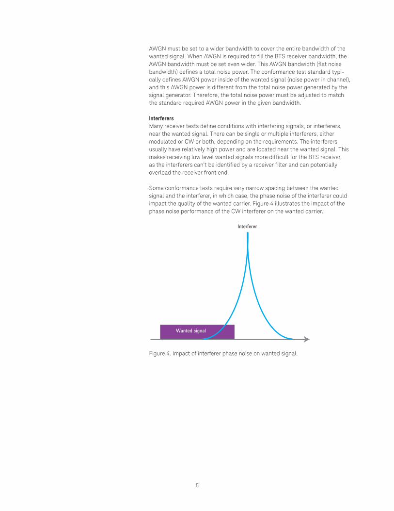
Additional test conditions for performing receiver testsAWGN and SNRTo simulate realistic propagation conditions in a generic and repeatable manner, it is often required to add random noise to the wanted signal. AWGN (Additive White Gaussian Noise) is commonly used as a random noise source that does not have a correlation to the wanted signal. BLER or throughput limits are typically defined based on SNR (Signal to Noise Ratio) which is the power ratio between the wanted carrier and AWGN. The signal generators used for receiver tests need AWGN generation capabilities. The following figure depicts the relationship between the signal and AWGN bandwidth and power.
Signal occupied bandwidth
Wanted signal
Flat noise bandwidth
Noise power in channel
SNR
AWGN
Signal generator
Feedback
BTS
Rx
Figure 2. Closed loop test configuration.
Figure 3. Wanted signal and AWGN.
5
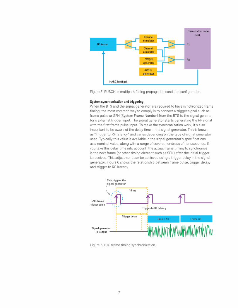
Figure 4. Impact of interferer phase noise on wanted signal.
AWGN must be set to a wider bandwidth to cover the entire bandwidth of the wanted signal. When AWGN is required to fill the BTS receiver bandwidth, the AWGN bandwidth must be set even wider. This AWGN bandwidth (flat noise bandwidth) defines a total noise power. The conformance test standard typi-cally defines AWGN power inside of the wanted signal (noise power in channel), and this AWGN power is different from the total noise power generated by the signal generator. Therefore, the total noise power must be adjusted to match the standard required AWGN power in the given bandwidth.
InterferersMany receiver tests define conditions with interfering signals, or interferers, near the wanted signal. There can be single or multiple interferers, either modulated or CW or both, depending on the requirements. The interferers usually have relatively high power and are located near the wanted signal. This makes receiving low level wanted signals more difficult for the BTS receiver, as the interferers can’t be identified by a receiver filter and can potentially overload the receiver front end.
Some conformance tests require very narrow spacing between the wanted signal and the interferer, in which case, the phase noise of the interferer could impact the quality of the wanted carrier. Figure 4 illustrates the impact of the phase noise performance of the CW interferer on the wanted carrier.
Interferer
Wanted signal

6
Multi-channel configurationAnother important test condition is the MIMO (Multi Input Multi Output) test configuration. Particularly with LTE and W-CDMA, the BTS has multiple receiver antennas to achieve higher data rates with spatial multiplexing, or bet-ter reception with receiver diversity. Some receiver tests require measurement of multiple receiver antennas at the same time with multiple UE signals that require 1x2 or 2x2 MIMO configurations. The following table shows LTE require-ments for MIMO configurations, using the TS36.141 receiver performance tests as an example.
Table 1. LTE receiver performance test requirements
Requirement number
Performance requirement name
Evolved Note B (eNB) feedback
Channel configuration
Channel model
8.2.1 PUSCH (Physical Uplink Shared Channel) in multipath fading propagation condition
HARQ 1x2, 1x4 Multipath fading
8.2.2 UL (Uplink) timing adjustment HARQ and TA 2x2 Moving propagation
8.2.3 HARQ-ACK multiplexed on PUSCH n/a 1x2 Multipath fading
8.2.4 High speed train condition HARQ 1x1, 1x2 Moving propagation
8.3.1 ACK missed detection for single user PUCCH (Physical Uplink Control Channel) format 1a
n/a
1x2, 1x4
Multipath fading8.3.2 CQI (Channel Quality Indicator) performance
requirements for PUCCH format 21x2
8.3.3 ACK missed detection for multi user PUCCH format 1a 4x2
8.4.1 PRACH (Physical Random Access Channel) false alarm probability and missed detection
1x2, 1x4
Channel fading simulationIn addition to MIMO configuration, fading simulations are required to verify the BTS’s ability to receive data from the UE under more stringent conditions. To simulate common usage scenarios, the standard defines various use models for handsets, including pedestrian, vehicle, high speed train, etc.
The following figure shows LTE’s PUSCH under a multipath fading propagation condition (clause 8.2.1 in Table 1) test setup with a 1x2 configuration, using 1 uplink signal with 2 receiver antennas (for receiver diversity). The UE signal is split into two paths and then channel simulation is applied to simulate a multipath fading condition. Finally AWGN is added to each of the paths and fed to each of BTS receiver antennas.
7
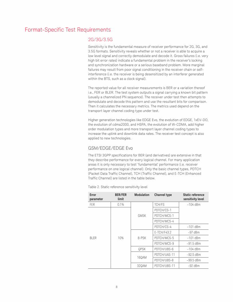
System synchronization and triggeringWhen the BTS and the signal generator are required to have synchronized frame timing, the most common way to comply is to connect a trigger signal such as frame pulse or SFN (System Frame Number) from the BTS to the signal genera-tor’s external trigger input. The signal generator starts generating the RF signal with the first frame pulse input. To make the synchronization work, it’s also important to be aware of the delay time in the signal generator. This is known as “Trigger to RF latency” and varies depending on the type of signal generator used. Typically this value is available in the signal generator’s specifications as a nominal value, along with a range of several hundreds of nanoseconds. If you take this delay time into account, the actual frame timing to synchronize is the next frame (or other timing element such as SFN) after the initial trigger is received. This adjustment can be achieved using a trigger delay in the signal generator. Figure 6 shows the relationship between frame pulse, trigger delay, and trigger to RF latency.
Frame #0
This triggers the signal generator
eNB frame trigger pulse
Signal generator RF output
Trigger delay
10 ms
Frame #1
Trigger-to-RF latency
BS tester
Channel simulator
Channel simulator
AWGN generator
AWGN generator
Base station under test
Rx
Rx
HARQ feedback
Figure 5. PUSCH in multipath fading propagation condition configuration.
Figure 6. BTS frame timing synchronization.
8
Error parameter
BER/FER limit
Modulation Channel type Static reference sensitivity level
FER 0.1%
GMSK
TCH/FS –104 dBm
BLER 10%
PDTCH/CS-1
PDTCH/MCS-1
PDTCH/MCS-4
PDTCH/CS-4 –101 dBm
8-PSK
E-TCH/F43.2 –97 dBm
PDTCH/MCS-5 –101 dBm
PDTCH/MCS-9 –91.5 dBm
QPSK PDTCH/UBS-6 –104 dBm
16QAMPDTCH/UAS-11 –92.5 dBm
PDTCH/UBS-8 –99.5 dBm
32QAM PDTCH/UBS-11 –92 dBm
Format-Specific Test Requirements
2G/3G/3.5G Sensitivity is the fundamental measure of receiver performance for 2G, 3G, and 3.5G formats. Sensitivity reveals whether or not a receiver is able to acquire a low level signal and correctly demodulate and decode it. Gross failures (i.e. very high bit error rates) indicate a fundamental problem in the receiver’s locking and synchronization hardware or a serious baseband problem. More marginal failures may result from poor signal conditioning in the receiver chain or self-interference (i.e. the receiver is being desensitized by an interferer generated within the BTS, such as a clock signal).
The reported value for all receiver measurements is BER or a variation thereof i.e., FER or BLER. The test system outputs a signal carrying a known bit pattern (usually a channelized PN sequence). The receiver under test then attempts to demodulate and decode this pattern and use the resultant bits for comparison. Then it calculates the necessary metrics. The metrics used depend on the transport layer channel coding type under test.
Higher generation technologies like EDGE Evo, the evolution of EDGE, 1xEV-DO, the evolution of cdma2000, and HSPA, the evolution of W-CDMA, add higher order modulation types and more transport layer channel coding types to increase the uplink and downlink data rates. The receiver test concept is also applied to new technologies.
GSM/EDGE/EDGE Evo The ETSI 3GPP specifications for BER (and derivatives) are extensive in that they describe performance for every logical channel. For many application areas it is only necessary to test ‘fundamental’ performance (i.e. receiver performance on one logical channel). Only the basic channel types, PDTCH (Packet Data Traffic Channel), TCH (Traffic Channel), and E-TCH (Enhanced Traffic Channel) are listed in the table below.
Table 2. Static reference sensitivity level
9
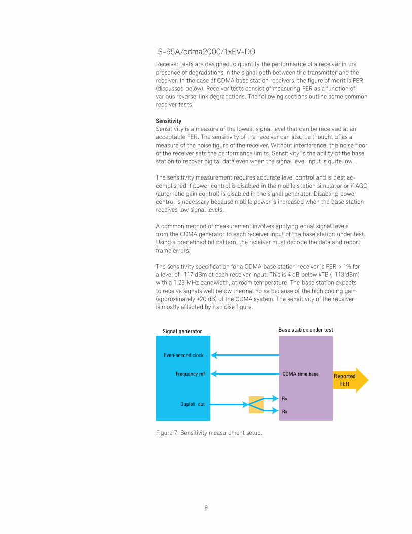
IS-95A/cdma2000/1xEV-DO Receiver tests are designed to quantify the performance of a receiver in the presence of degradations in the signal path between the transmitter and the receiver. In the case of CDMA base station receivers, the figure of merit is FER (discussed below). Receiver tests consist of measuring FER as a function of various reverse-link degradations. The following sections outline some common receiver tests.
SensitivitySensitivity is a measure of the lowest signal level that can be received at an acceptable FER. The sensitivity of the receiver can also be thought of as a measure of the noise figure of the receiver. Without interference, the noise floor of the receiver sets the performance limits. Sensitivity is the ability of the base station to recover digital data even when the signal level input is quite low.
The sensitivity measurement requires accurate level control and is best ac-complished if power control is disabled in the mobile station simulator or if AGC (automatic gain control) is disabled in the signal generator. Disabling power control is necessary because mobile power is increased when the base station receives low signal levels.
A common method of measurement involves applying equal signal levels from the CDMA generator to each receiver input of the base station under test. Using a predefined bit pattern, the receiver must decode the data and report frame errors.
The sensitivity specification for a CDMA base station receiver is FER > 1% for a level of –117 dBm at each receiver input. This is 4 dB below kTB (–113 dBm) with a 1.23 MHz bandwidth, at room temperature. The base station expects to receive signals well below thermal noise because of the high coding gain (approximately +20 dB) of the CDMA system. The sensitivity of the receiver is mostly affected by its noise figure.
Signal generator
Even-second clock
Frequency ref
Duplex out
Base station under test
Rx
CDMA time base
Rx
Reported FER
Figure 7. Sensitivity measurement setup.
10
Dynamic rangeDynamic range is the ability of the receiver to receive signals that are either very weak or very strong and is subject to the effects of linearity and noise figure. It is the ratio, expressed in dB, of the highest level signal that can be received to the lowest-level signal that can be received. As with sensitivity, dynamic range requires accurate level control.
Dynamic range uses the same setup as sensitivity. However, the signal is very large (–65 dBm) and tests the overload capability of the base station. The highest-level signal that can be received for the same 1% FER must then be measured to determine dynamic range. In this case, the input signal level is increased until the 1% FER is achieved.
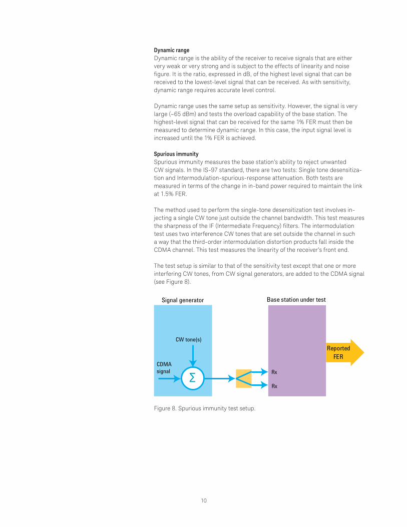
Spurious immunitySpurious immunity measures the base station’s ability to reject unwanted CW signals. In the IS-97 standard, there are two tests: Single tone desensitiza-tion and Intermodulation-spurious-response attenuation. Both tests are measured in terms of the change in in-band power required to maintain the link at 1.5% FER.
The method used to perform the single-tone desensitization test involves in-jecting a single CW tone just outside the channel bandwidth. This test measures the sharpness of the IF (Intermediate Frequency) filters. The intermodulation test uses two interference CW tones that are set outside the channel in such a way that the third-order intermodulation distortion products fall inside the CDMA channel. This test measures the linearity of the receiver’s front end.
The test setup is similar to that of the sensitivity test except that one or more interfering CW tones, from CW signal generators, are added to the CDMA signal (see Figure 8).
Signal generator
CW tone(s)
CDMA signal
Base station under test
Rx
Rx
Reported FER
Σ
Figure 8. Spurious immunity test setup.
11
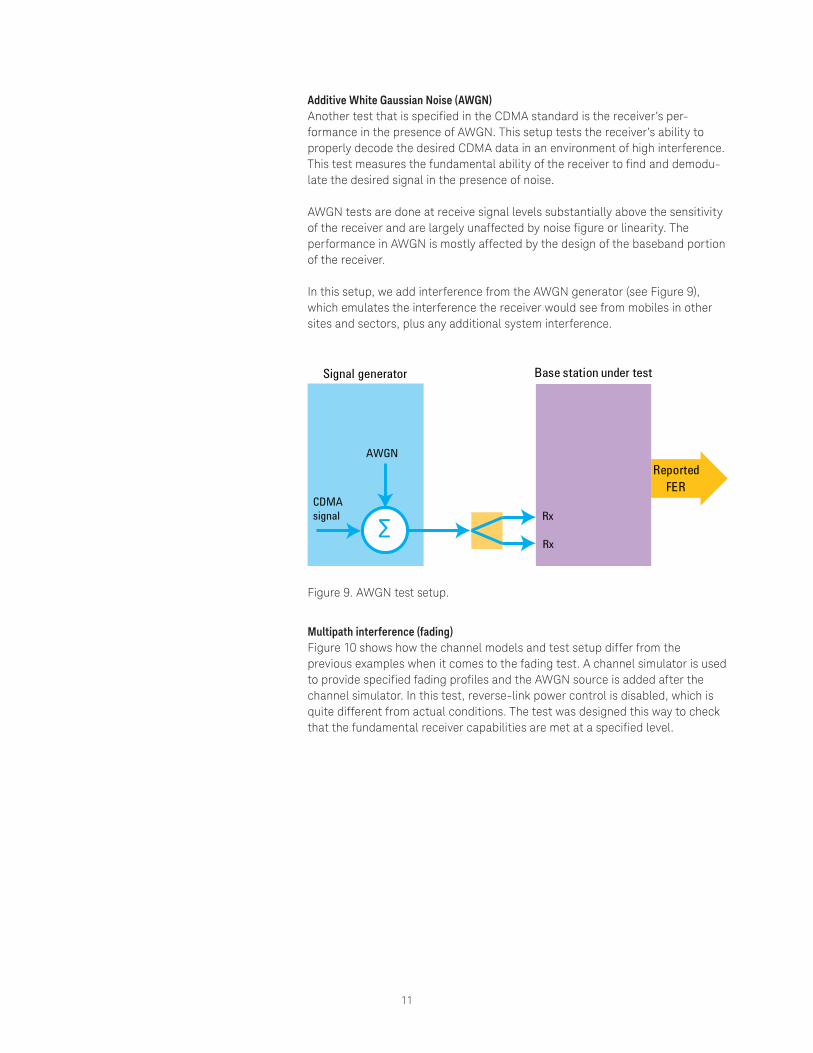
Additive White Gaussian Noise (AWGN)Another test that is specified in the CDMA standard is the receiver’s per-formance in the presence of AWGN. This setup tests the receiver’s ability to properly decode the desired CDMA data in an environment of high interference. This test measures the fundamental ability of the receiver to find and demodu-late the desired signal in the presence of noise.
AWGN tests are done at receive signal levels substantially above the sensitivity of the receiver and are largely unaffected by noise figure or linearity. The performance in AWGN is mostly affected by the design of the baseband portion of the receiver.
In this setup, we add interference from the AWGN generator (see Figure 9), which emulates the interference the receiver would see from mobiles in other sites and sectors, plus any additional system interference.
Signal generator
AWGN
CDMA signal
Base station under test
Rx
Rx
Reported FER
Σ
Figure 9. AWGN test setup.
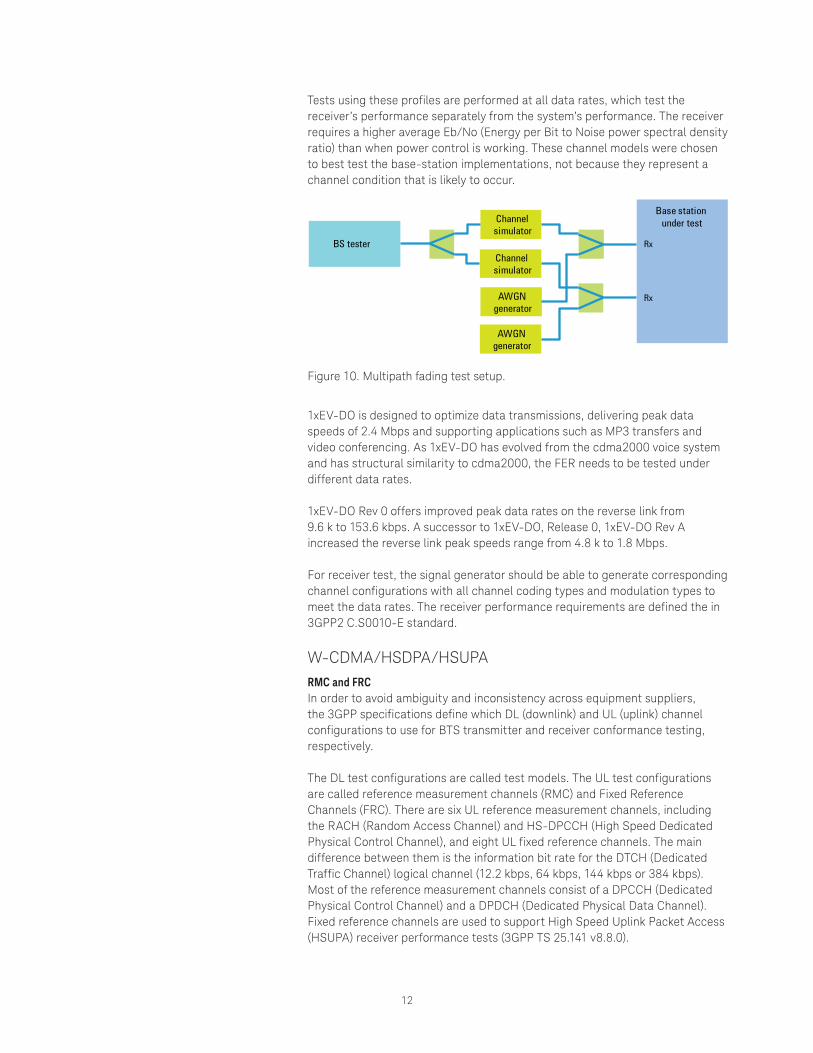
Multipath interference (fading)Figure 10 shows how the channel models and test setup differ from the previous examples when it comes to the fading test. A channel simulator is used to provide specified fading profiles and the AWGN source is added after the channel simulator. In this test, reverse-link power control is disabled, which is quite different from actual conditions. The test was designed this way to check that the fundamental receiver capabilities are met at a specified level.
12
Tests using these profiles are performed at all data rates, which test the receiver’s performance separately from the system’s performance. The receiver requires a higher average Eb/No (Energy per Bit to Noise power spectral density ratio) than when power control is working. These channel models were chosen to best test the base-station implementations, not because they represent a channel condition that is likely to occur.
BS tester
Channel simulator
Channel simulator
AWGN generator
AWGN generator
Base station under test
Rx
Rx
Figure 10. Multipath fading test setup.
1xEV-DO is designed to optimize data transmissions, delivering peak data speeds of 2.4 Mbps and supporting applications such as MP3 transfers and video conferencing. As 1xEV-DO has evolved from the cdma2000 voice system and has structural similarity to cdma2000, the FER needs to be tested under different data rates. 1xEV-DO Rev 0 offers improved peak data rates on the reverse link from 9.6 k to 153.6 kbps. A successor to 1xEV-DO, Release 0, 1xEV-DO Rev A increased the reverse link peak speeds range from 4.8 k to 1.8 Mbps. For receiver test, the signal generator should be able to generate corresponding channel configurations with all channel coding types and modulation types to meet the data rates. The receiver performance requirements are defined the in 3GPP2 C.S0010-E standard.
W-CDMA/HSDPA/HSUPA RMC and FRCIn order to avoid ambiguity and inconsistency across equipment suppliers, the 3GPP specifications define which DL (downlink) and UL (uplink) channel configurations to use for BTS transmitter and receiver conformance testing, respectively.
The DL test configurations are called test models. The UL test configurations are called reference measurement channels (RMC) and Fixed Reference Channels (FRC). There are six UL reference measurement channels, including the RACH (Random Access Channel) and HS-DPCCH (High Speed Dedicated Physical Control Channel), and eight UL fixed reference channels. The main difference between them is the information bit rate for the DTCH (Dedicated Traffic Channel) logical channel (12.2 kbps, 64 kbps, 144 kbps or 384 kbps). Most of the reference measurement channels consist of a DPCCH (Dedicated Physical Control Channel) and a DPDCH (Dedicated Physical Data Channel). Fixed reference channels are used to support High Speed Uplink Packet Access (HSUPA) receiver performance tests (3GPP TS 25.141 v8.8.0).
13
PRACHPRACH is used for system access and as such, correct PRACH reception functionality is critical to UE performance. In fact, tests for both RACH preamble detection and demodulation of RACH messages in both static and multipath conditions are required by the specifications.
A fully coded PRACH signal is required for testing PRACH reception. Configu-rable timing and a selectable signature for the preamble are desirable in order to verify preamble detection for different configurations. For example, one of the most interesting configurations consists of setting up the PRACH signal so that the message is not transmitted until a trigger from an AICH (Acquisition Indicator Channel) command from the BTS is received. Therefore, the stimulus source must be capable of accepting some sort of trigger signal for the message.
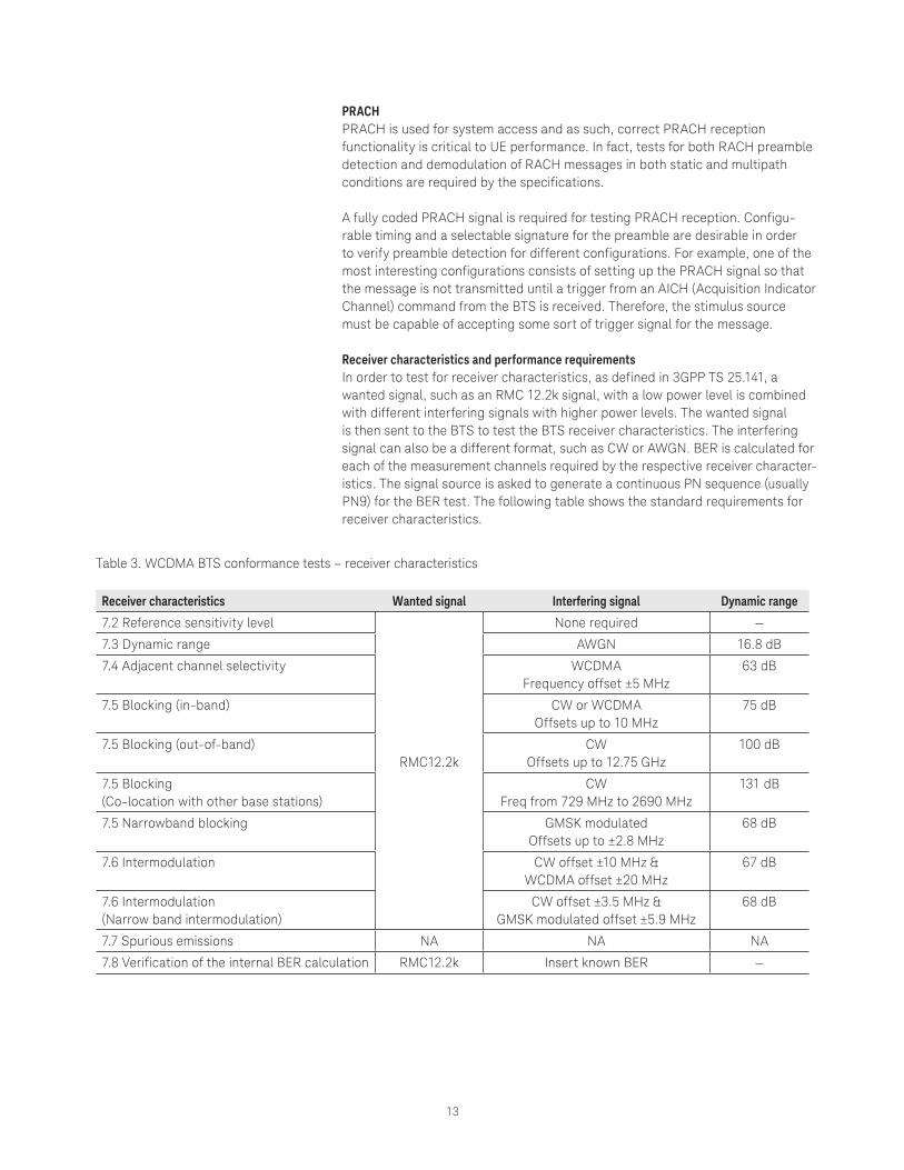
Receiver characteristics and performance requirementsIn order to test for receiver characteristics, as defined in 3GPP TS 25.141, a wanted signal, such as an RMC 12.2k signal, with a low power level is combined with different interfering signals with higher power levels. The wanted signal is then sent to the BTS to test the BTS receiver characteristics. The interfering signal can also be a different format, such as CW or AWGN. BER is calculated for each of the measurement channels required by the respective receiver character-istics. The signal source is asked to generate a continuous PN sequence (usually PN9) for the BER test. The following table shows the standard requirements for receiver characteristics.
Table 3. WCDMA BTS conformance tests – receiver characteristics
Receiver characteristics Wanted signal Interfering signal Dynamic range
7.2 Reference sensitivity level
RMC12.2k
None required —
7.3 Dynamic range AWGN 16.8 dB
7.4 Adjacent channel selectivity WCDMA Frequency offset ±5 MHz
63 dB
7.5 Blocking (in-band) CW or WCDMA Offsets up to 10 MHz
75 dB
7.5 Blocking (out-of-band) CW Offsets up to 12.75 GHz
100 dB
7.5 Blocking (Co-location with other base stations)
CW Freq from 729 MHz to 2690 MHz
131 dB
7.5 Narrowband blocking GMSK modulatedOffsets up to ±2.8 MHz
68 dB
7.6 Intermodulation CW offset ±10 MHz &WCDMA offset ±20 MHz
67 dB
7.6 Intermodulation (Narrow band intermodulation)
CW offset ±3.5 MHz &GMSK modulated offset ±5.9 MHz
68 dB
7.7 Spurious emissions NA NA NA
7.8 Verification of the internal BER calculation RMC12.2k Insert known BER —

14
Performance requirements, as defined in 3GPP TS 25.141 and summarized in Table 4, are specified for a number of test environments and multipath channel classes. The requirements only apply to those reference measurement channels that are supported by the base station. The wanted signals consist of RMC, PRACH and FRC.
The key performance metric for HSUPA, demodulation of the E-DPDCH (Enhanced Dedicated Physical Data Channel) signal under multipath fading conditions, is defined as the minimum throughput, R, the sum (in kilobits) of the information bit payloads (excluding the 24-bit CRC) successfully received during the test interval, divided by the duration of the test interval (in seconds). The throughput value R can be mapped unambiguously to a BLER metric.
Table 4. WCDMA BTS conformance tests – performance requirements
Performance requirements Wanted signal Channel model Channel configuration
Feedback
8.2 Demodulation under static propagation conditions RMC 12.2k,
64k, 144k, 384k
AWGN (no fading)
1x1 (without Rx diversity)
1x2
(2x Rx diversity)
—
8.3 Demodulation of DCH under multipath fading conditions
AWGN+ Case 1, 2, 3, 4 —
8.4 Demodulation of DCH under moving propagation conditions
RMC 12.2k, 64k
AWGN+ moving propagation —
8.5 Demodulation of DCH under birth/death propagation conditions
AWGN + birth-death propagation condition
—
8.5A Demodulation of DCH under high speed train conditions
RMC 12.2kAWGN+
Scenario 1, 2, 3 —
8.8.1 RACH preamble detection under static propagation conditions
PRACH(Preamble only)
AWGN (no fading) —
8.8.2 RACH preamble detection in multipath fading, case 3
AWGN+ Case 3
—
8.8.2A RACH preamble detection under high speed train conditions
AWGN+ Scenario 1, 2, 3
—
8.8.3 Demodulation of RACH message under static propagation conditions
PRACH
AWGN (no fading) —
8.8.4 Demodulation of RACH message in multipath fading, case 3
AWGN+ Case 3
—
8.8.5 Demodulation of RACH message under high speed train conditions
AWGN+ Scenario 1, 2, 3
—
8.11.1 ACK false alarm under static propagation conditions DPDCH+
DPCCH
AWGN (no fading) —
8.11.2 ACK false alarm under multipath fading conditions
AWGN+ Case 1, 2, 3,
—
8.11.3 ACK mis-detection under static propagation conditions RMC12.2k+HS-
DPCCH (ACK+CQI)
AWGN (no fading) —
8.11.4 ACK mis-detection under multipath fading conditions
AWGN+ Case 1, 2, 3,
—
8.12 Demodulation of E-DPDCH under multipath fading conditions
FRC1-8AWGN+
ITU PA3, PB3, VA30, VA120 HARQ
8.13 Performance of signalling detection for E-DPCCH under multipath fading conditions
FRC1, FRC4AWGN+
ITU PA3, PB3, VA30, VA120 HARQ
15
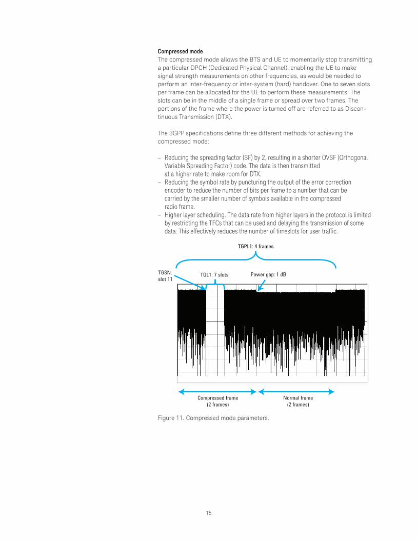
Compressed modeThe compressed mode allows the BTS and UE to momentarily stop transmitting a particular DPCH (Dedicated Physical Channel), enabling the UE to make signal strength measurements on other frequencies, as would be needed to perform an inter-frequency or inter-system (hard) handover. One to seven slots per frame can be allocated for the UE to perform these measurements. The slots can be in the middle of a single frame or spread over two frames. The portions of the frame where the power is turned off are referred to as Discon-tinuous Transmission (DTX).
The 3GPP specifications define three different methods for achieving the compressed mode:
– Reducing the spreading factor (SF) by 2, resulting in a shorter OVSF (Orthogonal Variable Spreading Factor) code. The data is then transmitted at a higher rate to make room for DTX.
– Reducing the symbol rate by puncturing the output of the error correction encoder to reduce the number of bits per frame to a number that can be carried by the smaller number of symbols available in the compressed radio frame.
– Higher layer scheduling. The data rate from higher layers in the protocol is limited by restricting the TFCs that can be used and delaying the transmission of some data. This effectively reduces the number of timeslots for user traffic.
TGPL1: 4 frames
TGSN: slot 11
TGL1: 7 slots
Compressed frame(2 frames)
Normal frame(2 frames)
Power gap: 1 dB
Figure 11. Compressed mode parameters.
16
Transmit power controlA BTS can minimize the amount of transmission power needed to achieve the required quality level by transmitting TPC (Transmit Power Control) commands based on SIR (Signal to Interference Ratio) measurements, thereby maximizing total system capacity. Power control at each slot is required to keep received signal quality constant under fading conditions.
Verifying the BTS’s real-time power control function (its ability to appropriately measure receiver SIR and generate TPC commands accordingly), requires the signal generator to simulate the UE by generating a signal that changes its power upon reception of different input levels that correspond to TPC commands from the BTS.
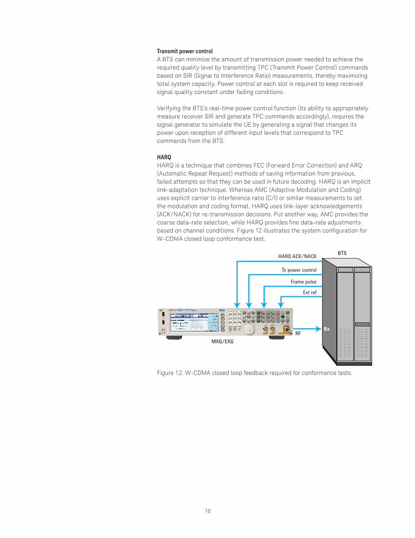
HARQHARQ is a technique that combines FEC (Forward Error Correction) and ARQ (Automatic Repeat Request) methods of saving information from previous, failed attempts so that they can be used in future decoding. HARQ is an implicit link-adaptation technique. Whereas AMC (Adaptive Modulation and Coding) uses explicit carrier to interference ratio (C/I) or similar measurements to set the modulation and coding format, HARQ uses link-layer acknowledgements (ACK/NACK) for re-transmission decisions. Put another way, AMC provides the coarse data-rate selection, while HARQ provides fine data-rate adjustments based on channel conditions. Figure 12 illustrates the system configuration for W-CDMA closed loop conformance test.
BTS
RxRF
HARQ ACK/NACK
Tx power control
Frame pulse
Ext ref
MXG/EXG
Figure 12. W-CDMA closed loop feedback required for conformance tests.
17
3.9G and 4G
HSPA+HSPA+ introduces new functionality and features, including UE DTX and MIMO, as well as dual-cell operation. BTS receiver measurements for HSPA+ are mostly used in the R&D function test phase.
UE-DTX mode for CPC (Continuous Packet Connectivity) simulationUE-DTX mode is used for continuous packet connectivity and reduces UE battery consumption. The UE can switch into DTX mode after ending the transmission of the DPDCH by also stopping the continuous transmissions of the DPCCH and HS-DPCCH. To test a BTS receiver’s performance in the UE-DTX mode, a signal source is required to flexibly configure the UE control channels for user-defined DTX patterns.
HS-DPCCH (MIMO and/or dual cell)The downlink MIMO and dual-cell operation in HSPA+, which is used for increased throughput and reliability as well as uplink load balancing, requires new capabilities in the UE uplink signal. In downlink MIMO operation, the UE should provide feedback to Node B regarding channel quality (CQI) and desired precoding control information (PCI) from the two transport channels. Similarly, in dual-cell mode, the UE must provide feedback for the two downlink signals coming from each carrier.
In both cases, the UE provides the feedback through the HS-DPCCH, which is now modified to include HARQ messages and a composite PCI/CQI value.
To enable the test for the BTS in dual-cell, MIMO, and dual-cell with MIMO configurations, a signal source is used to simulate a UE, to enable the HS-DPCCH to send the appropriate feedback signal to the BTS.
LTEThis section describes BTS receiver conformance test requirements specific to the LTE FDD (Frequency Division Duplex) and TDD (Time Division Multiplex) standards.
Receiver conformance test types3GPP standard TS36.141 defines two types of BTS receiver conformance tests, receiver characteristics, and receiver performance requirements. The former mainly tests the BTS receiver’s sensitivity when different types of interferers, such as AWGN, CW, and E-UTRA (Evolved Universal, Terrestrial Radio Access) are in close proximity to the wanted carrier. The test is performed under varying conditions such as a range of offset frequencies and interferer amplitudes. Each of the multiple receiver antennas is tested separately, while the other antenna ports are terminated. Thus, there’s no need to have a MIMO configuration. Conversely, receiver performance tests require MIMO configuration and channel simulation to perform receiver tests under various propagation conditions. All test conditions include a standard-specified SNR, signal setup, and AWGN level. Additionally, several tests assume a closed loop test configuration for the HARQ and TA (Timing Advance) feedback from the BTS.
18
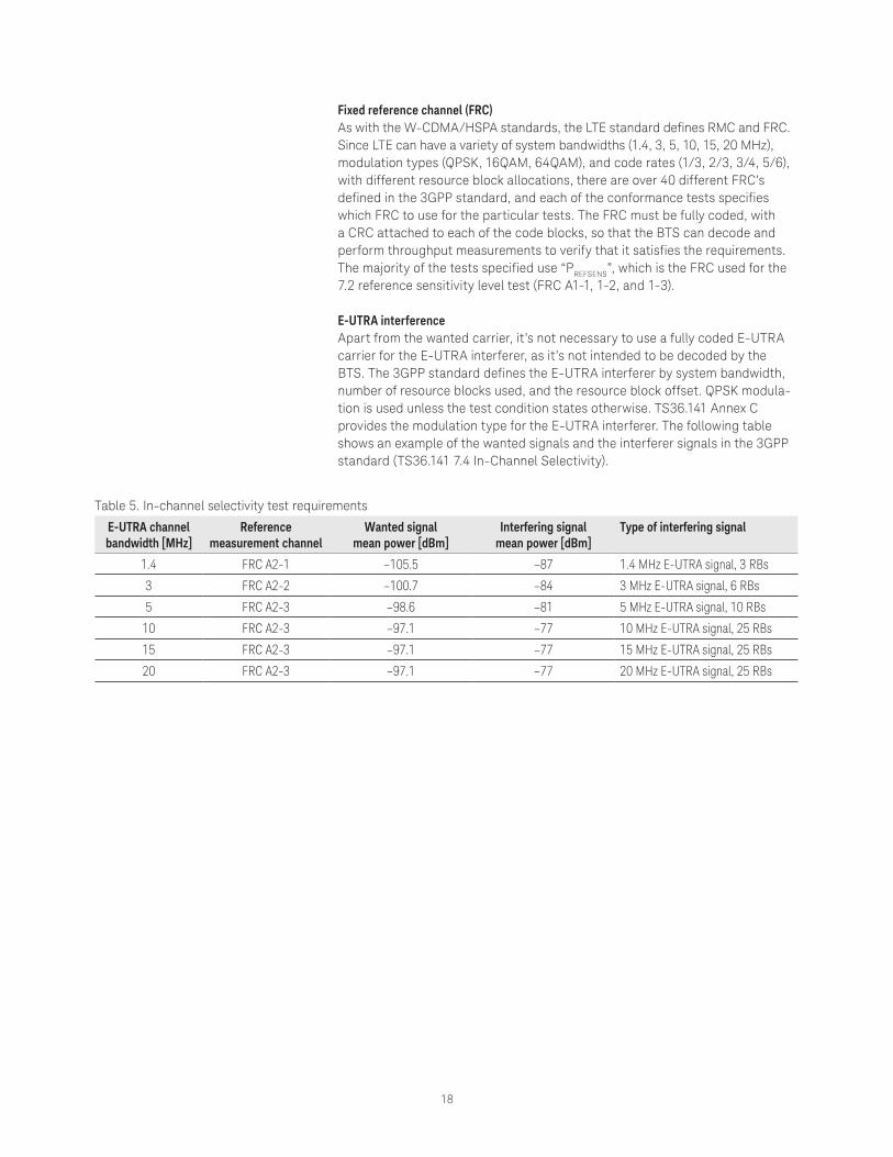
Fixed reference channel (FRC)As with the W-CDMA/HSPA standards, the LTE standard defines RMC and FRC. Since LTE can have a variety of system bandwidths (1.4, 3, 5, 10, 15, 20 MHz), modulation types (QPSK, 16QAM, 64QAM), and code rates (1/3, 2/3, 3/4, 5/6), with different resource block allocations, there are over 40 different FRC’s defined in the 3GPP standard, and each of the conformance tests specifies which FRC to use for the particular tests. The FRC must be fully coded, with a CRC attached to each of the code blocks, so that the BTS can decode and perform throughput measurements to verify that it satisfies the requirements. The majority of the tests specified use “PREFSENS”, which is the FRC used for the 7.2 reference sensitivity level test (FRC A1-1, 1-2, and 1-3).
E-UTRA interferenceApart from the wanted carrier, it’s not necessary to use a fully coded E-UTRA carrier for the E-UTRA interferer, as it’s not intended to be decoded by the BTS. The 3GPP standard defines the E-UTRA interferer by system bandwidth, number of resource blocks used, and the resource block offset. QPSK modula-tion is used unless the test condition states otherwise. TS36.141 Annex C provides the modulation type for the E-UTRA interferer. The following table shows an example of the wanted signals and the interferer signals in the 3GPP standard (TS36.141 7.4 In-Channel Selectivity).
Table 5. In-channel selectivity test requirements
E-UTRA channel bandwidth [MHz]
Reference measurement channel
Wanted signal mean power [dBm]
Interfering signal mean power [dBm]
Type of interfering signal
1.4 FRC A2-1 –105.5 –87 1.4 MHz E-UTRA signal, 3 RBs
3 FRC A2-2 –100.7 –84 3 MHz E-UTRA signal, 6 RBs
5 FRC A2-3 –98.6 –81 5 MHz E-UTRA signal, 10 RBs
10 FRC A2-3 –97.1 –77 10 MHz E-UTRA signal, 25 RBs
15 FRC A2-3 –97.1 –77 15 MHz E-UTRA signal, 25 RBs
20 FRC A2-3 –97.1 –77 20 MHz E-UTRA signal, 25 RBs
19
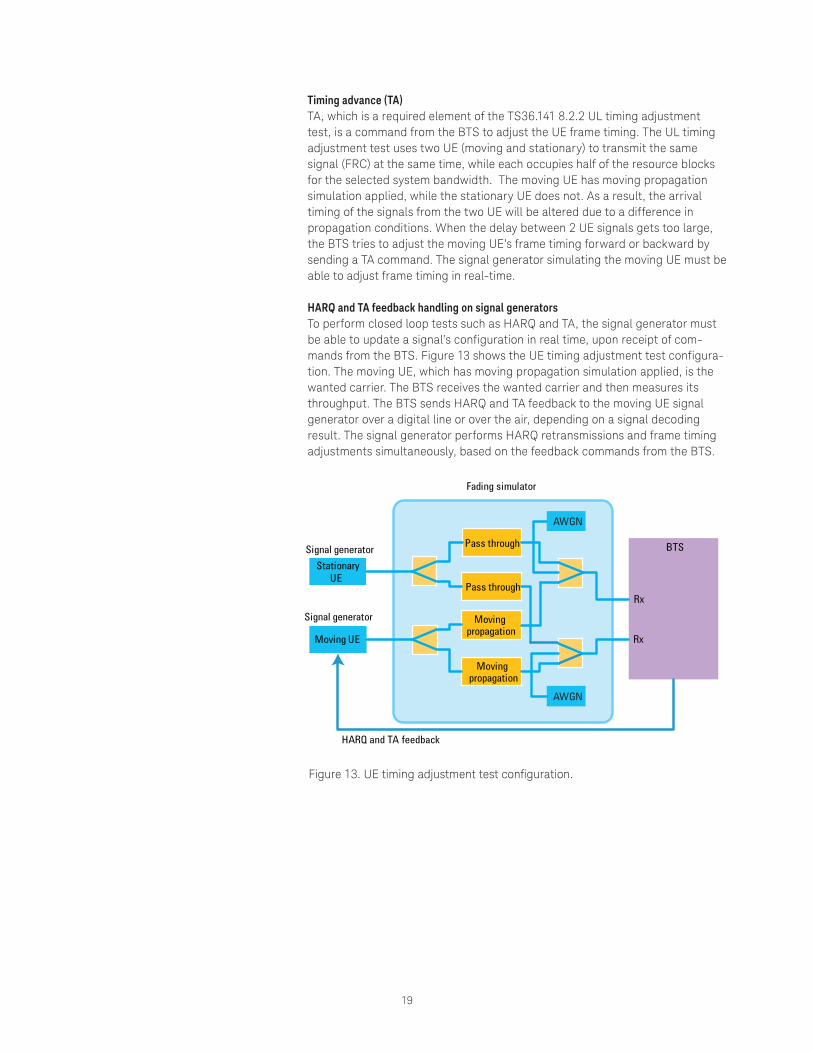
Timing advance (TA)TA, which is a required element of the TS36.141 8.2.2 UL timing adjustment test, is a command from the BTS to adjust the UE frame timing. The UL timing adjustment test uses two UE (moving and stationary) to transmit the same signal (FRC) at the same time, while each occupies half of the resource blocks for the selected system bandwidth. The moving UE has moving propagation simulation applied, while the stationary UE does not. As a result, the arrival timing of the signals from the two UE will be altered due to a difference in propagation conditions. When the delay between 2 UE signals gets too large, the BTS tries to adjust the moving UE’s frame timing forward or backward by sending a TA command. The signal generator simulating the moving UE must be able to adjust frame timing in real-time.
HARQ and TA feedback handling on signal generatorsTo perform closed loop tests such as HARQ and TA, the signal generator must be able to update a signal’s configuration in real time, upon receipt of com-mands from the BTS. Figure 13 shows the UE timing adjustment test configura-tion. The moving UE, which has moving propagation simulation applied, is the wanted carrier. The BTS receives the wanted carrier and then measures its throughput. The BTS sends HARQ and TA feedback to the moving UE signal generator over a digital line or over the air, depending on a signal decoding result. The signal generator performs HARQ retransmissions and frame timing adjustments simultaneously, based on the feedback commands from the BTS.
Pass through
Pass through
AWGN
AWGN
BTS
HARQ and TA feedback
Moving UE
Stationary UE
Rx
Rx
Moving propagation
Moving propagation
Signal generator
Signal generator
Fading simulator
Figure 13. UE timing adjustment test configuration.
20
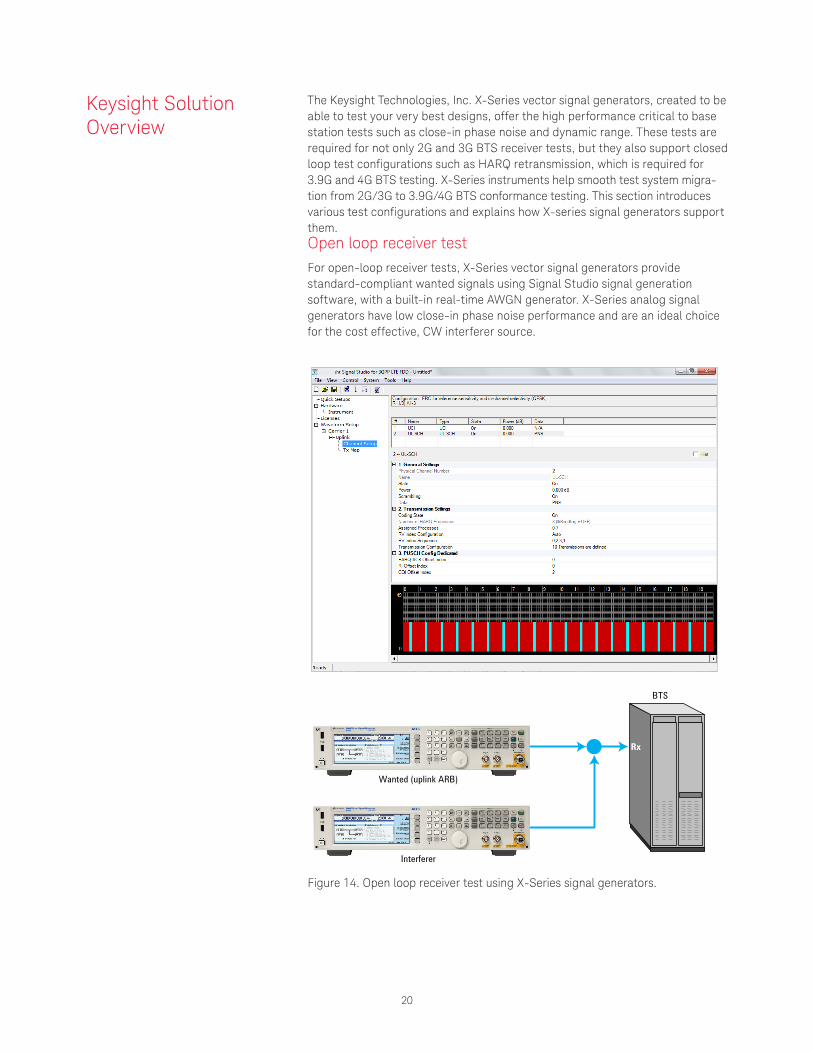
The Keysight Technologies, Inc. X-Series vector signal generators, created to be able to test your very best designs, offer the high performance critical to base station tests such as close-in phase noise and dynamic range. These tests are required for not only 2G and 3G BTS receiver tests, but they also support closed loop test configurations such as HARQ retransmission, which is required for 3.9G and 4G BTS testing. X-Series instruments help smooth test system migra-tion from 2G/3G to 3.9G/4G BTS conformance testing. This section introduces various test configurations and explains how X-series signal generators support them.Open loop receiver testFor open-loop receiver tests, X-Series vector signal generators provide standard-compliant wanted signals using Signal Studio signal generation software, with a built-in real-time AWGN generator. X-Series analog signal generators have low close-in phase noise performance and are an ideal choice for the cost effective, CW interferer source.
BTS
Rx
Wanted (uplink ARB)
Interferer
Figure 14. Open loop receiver test using X-Series signal generators.
Keysight Solution Overview
21
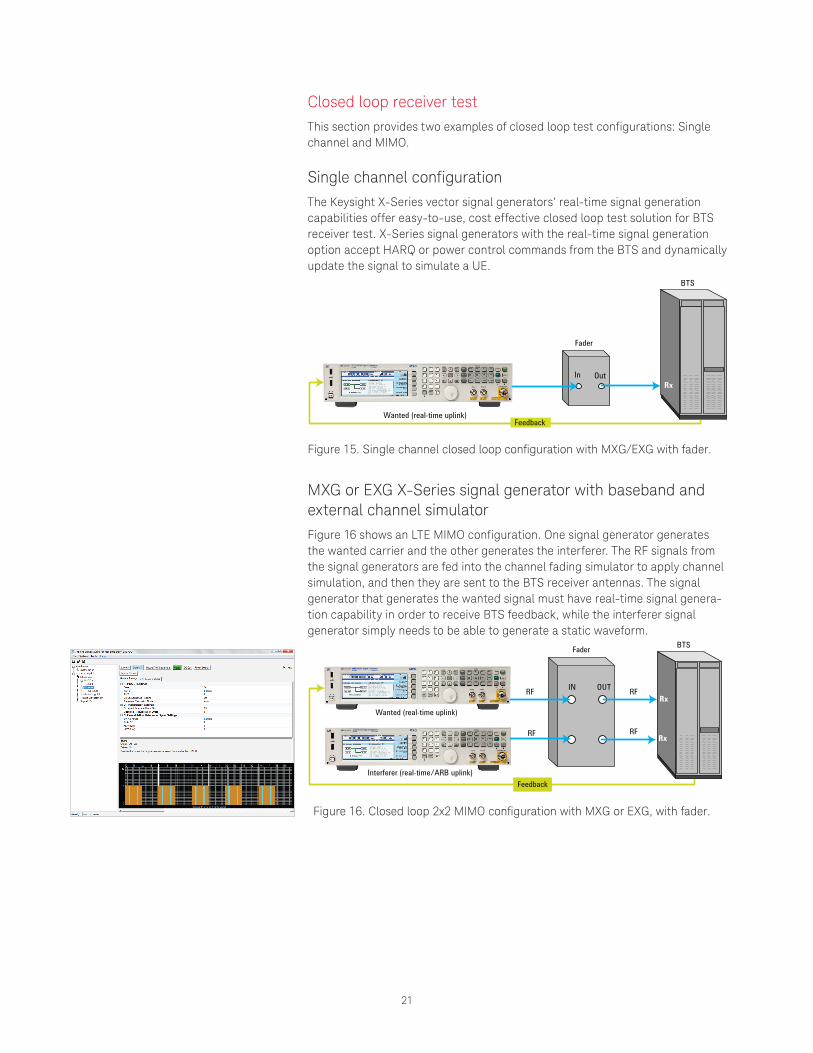
Closed loop receiver testThis section provides two examples of closed loop test configurations: Single channel and MIMO.
Single channel configurationThe Keysight X-Series vector signal generators’ real-time signal generation capabilities offer easy-to-use, cost effective closed loop test solution for BTS receiver test. X-Series signal generators with the real-time signal generation option accept HARQ or power control commands from the BTS and dynamically update the signal to simulate a UE.
BTS
Fader
Rx
Wanted (real-time uplink)
In Out
Feedback
Figure 15. Single channel closed loop configuration with MXG/EXG with fader.
MXG or EXG X-Series signal generator with baseband and external channel simulatorFigure 16 shows an LTE MIMO configuration. One signal generator generates the wanted carrier and the other generates the interferer. The RF signals from the signal generators are fed into the channel fading simulator to apply channel simulation, and then they are sent to the BTS receiver antennas. The signal generator that generates the wanted signal must have real-time signal genera-tion capability in order to receive BTS feedback, while the interferer signal generator simply needs to be able to generate a static waveform.
BTS
RF
RF
RF
RFRx
Rx
Wanted (real-time uplink)
Interferer (real-time/ARB uplink)
IN OUT
Fader
Feedback
Keysight
Figure 16. Closed loop 2x2 MIMO configuration with MXG or EXG, with fader.
22
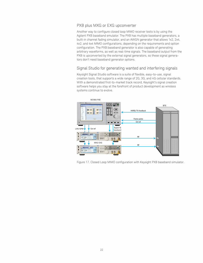
PXB plus MXG or EXG upconverter Another way to configure closed loop MIMO receiver tests is by using the Agilent PXB baseband emulator. The PXB has multiple baseband generators, a built-in channel fading simulator, and an AWGN generator that allows 1x2, 2x4, 4x2, and 4x4 MIMO configurations, depending on the requirements and option configuration. The PXB baseband generator is also capable of generating arbitrary waveforms, as well as real-time signals. The baseband output from the PXB is upconverted by the external signal generators, so these signal genera-tors don’t need baseband generator options.
Signal Studio for generating wanted and interfering signalsKeysight Signal Studio software is a suite of flexible, easy-to-use, signal creation tools, that supports a wide range of 2G, 3G, and 4G cellular standards. With a demonstrated first-to-market track record, Keysight’s signal creation software helps you stay at the forefront of product development as wireless systems continue to evolve.
BTS
HARQ/TA feedback
Frame pulseExt ref
Ext ref
RF
RF Rx
Rx
N5106A PXB
MXG/EXG
Digital IQ basebandLAN/GPIB
Figure 17. Closed Loop MIMO configuration with Keysight PXB baseband simulator.
23
This section provides additional information on the test requirements discussed in this application note.
Signal types used for BTS transmitter and receiver testsThere are several different kinds of signals for testing BTS transmitter compo-nents and receivers. The following information includes a detailed review of the various signals and explanations as to when to use each of them.
Arbitrary waveform with physical layer codingThis type of signal includes physical layer coding, such as modulation and filtering, but it cannot be used for receiver testing because there’s no coding applied to the waveform. It is optimized for transmitter component testing with realistic CCDF (Complementary Cumulative Distribution Function) curves and good ACPR (Adjacent Channel Power Ratio) and EVM (Error Vector Magnitude) characteristics, which are required for high performance component tests. Signals defined for transmitter tests such as Test Models or E-TM (Evolved Test Model) use this type of waveform. It can also be used as an interferer for receiver tests that don’t require transport layer coding.
Arbitrary waveform with transport layer codingThis type of signal is generated by performing transport layer coding, such as FEC, and physical layer coding. It can be used as an actual signal and as such, the receiver can decode the signal and perform a CRC check to verify data, which is required to perform BLER or throughput tests. When an arbitrary waveform is generated, it must be stored in the baseband memory. It is limited in waveform length and repeatedly plays back short cycle data. Unless there is a very large amount of baseband memory in the signal generator, the arbitrary waveform is not ideal for BER tests because it requires very large waveforms that contain entire PN sequences. RMC (Reference Measurement Channel) or FRC, which are defined by 3GPP for receiver testing use this type of waveform. X-Series vector signal generators offer up to a 1G capacity sample arbitrary memory capable of holding waveforms for BER tests.
Real-time signalReal-time signals mostly have the same transport layer coding applied as arbitrary waveforms, which means that they can be used for receiver tests. The key difference, as compared to the arbitrary waveform, is that transport layer coding is performed when the signal is actually generated. Since there’s no need to store entire waveforms in the baseband memory, there’s no theoretical limitation for waveform length. This makes real-time signals ideal for performing BER tests.
Also, with real-time signal generation, it’s possible to change signal configura-tion dynamically, based on the input from outside, such as from the BTS.
Appendices
24
LTE HARQ overviewThere are several differences in HARQ between FDD and TDD LTE because of a difference in the frame structure. This section provides a high level overview of how the FDD and TDD LTE HARQ work.
HARQ for LTE FDDLTE FDD uplink has 8 HARQ processes running synchronously and in parallel. 1 HARQ process length is same as 1 subframe (1 ms). One HARQ period takes 8 ms, therefore it will synchronize with frame timing every 40 ms, or 4 frames. The UE transmits new data only after it has received ACK from the BTS. Having eight processes run in parallel avoids having the whole HARQ process stalled due to one retransmission request. In each process, the UE sends new data and the BTS has 4 subframes to decode and then check CRC to acknowledge whether data is received correctly (ACK) or incorrectly (NACK). Upon receipt of acknowledgment, the UE has another 4 subframes for either sending new data (ACK) or retransmitting data (NACK). The UE retransmits original data again, but with an incremented RV (redundancy version) index with NACK to help the BTS decode the data more reliably.
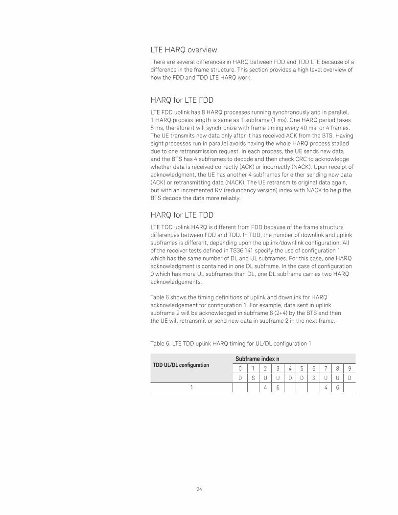
HARQ for LTE TDDLTE TDD uplink HARQ is different from FDD because of the frame structure differences between FDD and TDD. In TDD, the number of downlink and uplink subframes is different, depending upon the uplink/downlink configuration. All of the receiver tests defined in TS36.141 specify the use of configuration 1, which has the same number of DL and UL subframes. For this case, one HARQ acknowledgment is contained in one DL subframe. In the case of configuration 0 which has more UL subframes than DL, one DL subframe carries two HARQ acknowledgements.
Table 6 shows the timing definitions of uplink and downlink for HARQ acknowledgement for configuration 1. For example, data sent in uplink subframe 2 will be acknowledged in subframe 6 (2+4) by the BTS and then the UE will retransmit or send new data in subframe 2 in the next frame.
Table 6. LTE TDD uplink HARQ timing for UL/DL configuration 1
TDD UL/DL configurationSubframe index n
0 1 2 3 4 5 6 7 8 9
D S U U D D S U U D
1 4 6 4 6
25
Literature
X-Series Signal Generator Selection Guide, Literature number 5990-9956EN
X-Series Signal Generator Brochure, Literature number 5990-9957EN
EXG Data Sheet, Literature number 5991-0039EN
MXG Data Sheet, Literature number 5991-0038EN
EXG Configuration Guide, Literature number 5990-9958EN
MXG Configuration Guide, Literature number 5990-9959EN
LTE Logo and LTE-Advanced Logo are trademarks of ETSI.
www.keysight.com/find/X-Series_sg www.keysight.com/find/SignalStudio
26 | Keysight | Transition from 2G/3G to 3.9G/4G Base Station Receiver Conformance Test - Application Note
This information is subject to change without notice.© Keysight Technologies, 2017Published in USA, December 1, 20175991-0280ENwww.keysight.com
For more information on Keysight Technologies’ products, applications or services, please contact your local Keysight office. The complete list is available at:www.keysight.com/find/contactus
Americas Canada (877) 894 4414Brazil 55 11 3351 7010Mexico 001 800 254 2440United States (800) 829 4444
Asia PacificAustralia 1 800 629 485China 800 810 0189Hong Kong 800 938 693India 1 800 11 2626Japan 0120 (421) 345Korea 080 769 0800Malaysia 1 800 888 848Singapore 1 800 375 8100Taiwan 0800 047 866Other AP Countries (65) 6375 8100
Europe & Middle EastAustria 0800 001122Belgium 0800 58580Finland 0800 523252France 0805 980333Germany 0800 6270999Ireland 1800 832700Israel 1 809 343051Italy 800 599100Luxembourg +32 800 58580Netherlands 0800 0233200Russia 8800 5009286Spain 800 000154Sweden 0200 882255Switzerland 0800 805353
Opt. 1 (DE)Opt. 2 (FR)Opt. 3 (IT)
United Kingdom 0800 0260637
For other unlisted countries:www.keysight.com/find/contactus(BP-9-7-17)
DEKRA CertifiedISO9001 Quality Management System
www.keysight.com/go/qualityKeysight Technologies, Inc.DEKRA Certified ISO 9001:2015Quality Management System
Evolving Since 1939Our unique combination of hardware, software, services, and people can help you reach your next breakthrough. We are unlocking the future of technology. From Hewlett-Packard to Agilent to Keysight.
myKeysightwww.keysight.com/find/mykeysightA personalized view into the information most relevant to you.
http://www.keysight.com/find/emt_product_registrationRegister your products to get up-to-date product information and find warranty information.
Keysight Serviceswww.keysight.com/find/serviceKeysight Services can help from acquisition to renewal across your instrument’s lifecycle. Our comprehensive service offerings—one-stop calibration, repair, asset management, technology refresh, consulting, training and more—helps you improve product quality and lower costs.
Keysight Assurance Planswww.keysight.com/find/AssurancePlansUp to ten years of protection and no budgetary surprises to ensure your instruments are operating to specification, so you can rely on accurate measurements.
Keysight Channel Partnerswww.keysight.com/find/channelpartnersGet the best of both worlds: Keysight’s measurement expertise and product breadth, combined with channel partner convenience.