Keysight Technologies E1963A W-CDMA Mobile Test...
40
Keysight Technologies E1963A W-CDMA Mobile Test Application For the E5515C/E (8960) Wireless Communications Test Set Technical Overview
Transcript of Keysight Technologies E1963A W-CDMA Mobile Test...

Keysight TechnologiesE1963A W-CDMA Mobile Test ApplicationFor the E5515C/E (8960) Wireless Communications Test Set
Technical Overview
Introduction
Accelerate UMTS test plan development and get your devices to market sooner, while ensuring compliance with TS 34.121-1 test standards.
The Keysight Technologies, Inc. E1963A W-CDMA mobile test application, when used with the Keysight GSM, GPRS, and EGPRS applications, is the industry standard for universal mobile telecommunications (UMTS) mobile test. Keysight’s 8960 (E5515C/E) test set provides you with a single hardware platform that covers all the UMTS/3GPP (Third Generation Partnership Project) radio formats: W-CDMA, HSPA, GSM, GPRS, EGPRS, and TD-SCDMA.
Exceed your calibration test time goals with the E1999A-202 fast device tune measurement. Simultaneously calibrate your device’s transmitter (Tx) output power and receiver (Rx) input level across level and frequency. E1999A-202 is a superset of the discontinued E1999A-201. It not only offers the equivalent capabilities of the E1999A-201, it is enhanced to reduce the calibration test times for W-CDMA, cdma2000®, and 1xEV-DO wireless devices with smaller step size support (10 ms step size versus 20 ms step size).
Reach your high-volume production goals by moving prototypes quickly into production with this test solution’s fast and repeatable measurements, accurate characterization, and ease of programming.
The HSPA, W-CDMA, GSM, GPRS, and EGPRS product combination delivers a complete and integrated UMTS test solution in a single box. FM radio source, a single channel GPS source (E1999A-206), and PESQ measurement (E1999A-301) are also added into the test box for FM radio receiver calibration, GPS receiver calibration, and audio quality test without the need for an external audio analyzer. This fast, one-box approach simplifies your production process and increases your production line effectiveness.
With the most complete test functionality for 3GPP TS 34.121-1 Section 5 and 6 tests, E1963A HSPA Options 403, 405, 413, 423, 433, and 435 provide fast, flexible measurements and options in user equipment (UE) connectivity, giving design and manufacturing test engineers more flexibility in creating test plans and the assurance that designs meet technology standards. Option 433 pro-vides you with the functionality to test 42 Mbps downlink dual carrier (DC-HSDPA) and dual band dual carrier HSDPA (DB-DC-HSDPA) throughput in RB test mode and FDD test mode connection, and Option 435 allows validation of single and dual stream MIMO using 16QAM for a maximum data rate of 28 Mbps or 64QAM for 42 Mbps in RB test mode and FDD test mode connection.

03 | Keysight | E1963A W-CDMA Mobile Test Application - Technical Overview
Key Capabilities – CS voice handovers between GSM and W-CDMA on two test sets – Fast device calibration across level and frequency simultaneously – Test HSDPA MIMO devices (HS-DSCH categories 15-20) as defined in 3GPP TS 34.121-1 – Test devices that support downlink dual carrier and dual band dual carrier
(HS-DSCH categories 20-24) – Test HSPA devices (HS-DSCH categories 1-14, 17-18 and E-DCH categories 1-7)
as defined in 3GPP TS 34.121-1 – Switch between HSPA sub-test conditions while on an active connection – Test all UMTS technologies with one connection maintained throughout – Test all frequency bands I through XIV, XIX, XX, and XXI – FM and GPS receiver calibration in one box – Test vocoder speech quality using the industry standard PESQ algorithm
Tx measurements W-CDMA HSDPA HSUPA
Thermal power Yes Yes Yes
Channel power Yes Yes Yes
Adjacent channel leakage ratio Yes Yes Yes
Waveform quality Yes Yes Yes
Spectrum emission mask Yes Yes Yes
Phase discontinuity Yes Yes Yes
Inner loop power Yes
Occupied bandwidth Yes Yes Yes
Code domain power Yes Yes Yes
IQ constellation Yes Yes Yes
Tx on/off power Yes Yes Yes
Frequency stability Yes Yes Yes
Dynamic power analysis Yes Yes Yes
Tx dynamic power Yes
Spectrum monitor Yes Yes Yes
Rx measurements W-CDMA HSDPA HSUPA
Loopback BER Yes N/A N/A
BLER on DPCH (W-CDMA) Yes N/A N/A
HBLER on HS-DPCCH (HSDPA) N/A Yes N/A

04 | Keysight | E1963A W-CDMA Mobile Test Application - Technical Overview
3GPP TS 34.121 Adherence 3GPP TS 34.121-1
Test description E1963A
5.2 Maximum output power Yes
5.2A Maximum output power with HS-DPCCH (Release 5 only) Yes5
5.2AA Maximum output power with HS-DPCCH (Release 6 and later) Yes5
5.2B Maximum output power with HS-DPCCH and E-DCH Yes5
5.2C UE relative code domain power accuracy Yes5
5.2D UE relative code domain power accuracy for HS-DPCCH and E-DCH Yes5
5.2E UE relative code domain power accuracy for HS-DPCCH and E-DCH with 16QAM Yes5
5.3 Frequency error Yes
5.4.1 Open-loop power control Yes
5.4.2 Inner-loop power control Yes
5.4.3 Minimum output power Yes
5.4.4 Out-of-sync handling of output power E6703X2
5.5.1 Transmit off power Yes
5.5.2 Transmit on/off time mask Yes
5.6 Change of TFC E6703X
5.7 Power setting in UL compressed mode
5.7A HS-DPCCH Yes5
5.8 Occupied bandwidth (OBW) Yes
5.9 Spectrum emission mask (SEM) Yes
5.9A Spectrum emission mask with HS-DPCCH Yes5
5.9B Spectrum emission mask with E-DCH Yes5
5.10 Adjacent channel leakage power ratio (ACLR) Yes
5.10A ACLR with HS-DPCCH Yes5
5.10B ACLR with E-DCH Yes5
5.11 Spurious emissions Yes2
5.12 Transmit intermodulation Yes3
5.13.1 Error vector magnitude (EVM) Yes
5.13.1A Error vector magnitude (EVM) with HS-DPCCH Yes5
5.13.1AA EVM and phase discontinuity with HS-DPCCH Yes5
5.13.1AAA EVM and IQ origin offset for HS-DPCCH and E-DCH with 16QAM Yes5
5.13.2 Peak code domain error Yes
5.13.2A Relative code domain error with HS-DPCCH Yes5
5.13.2B Relative code domain error with HS-DPCCH and E-DCH Yes5
5.13.2C Relative code domain error for HS-DPCCH and E-DCH with 16QAM Yes5
5.13.3 Phase discontinuity measurement Yes
5.13.4 PRACH preamble quality E6703X
1. Requires use of external source.2. Requires use of external spectrum analyzer.3. Requires use of external spectrum analyzer and source.4. Internal fading is possible using the N5106A PXB baseband generator
and channel emulator. Most of these tests require external instrumentation such as faders. Consult TS 34.121-1 for details.
5. Requires feature option license.

05 | Keysight | E1963A W-CDMA Mobile Test Application - Technical Overview
3GPP TS 34.121-1 (continued)
Test description E1963A/E6703X
6.2 Reference sensitivity Yes
6.2A Reference sensitivity level for DC-HSDPA Yes5
6.2B Reference sensitivity level for DB-DCHSDPA Yes5
6.3 Maximum input level Yes5
6.3A Maximum input level for HS+DPCCH reception (16QAM) Yes5
6.3B Maximum input level for HS+PDSCH reception (64QAM) Yes5
6.3C Maximum input level for DC-HSDPA reception (16QAM) Yes5
6.3D Maximum input level for DC-HSDPA reception (64QAM) Yes5
6.3E Maximum input level for DB-DC-HSDPA reception (16QAM) Yes5
6.3F Maximum input level for DB-DC-HSDPA reception (64QAM) Yes5
6.4 Adjacent channel selectivity (ACS) (Release 99 and Release 4) Yes1
6.4A ACS (Release 5 and later releases) Yes1
6.4B Adjacent channel selectivity (ACS) for DC-HSDPA Yes1
6.4C Adjacent channel selectivity (ACS) for DB-DC-HSDPA Yes1
6.5 Blocking characteristics Yes1
6.5A Blocking characteristics for DC-HSDPA Yes1
6.5B Blocking characteristics for DB-DC-HSDPA Yes1
6.6 Spurious response Yes1
6.6A Spurious response for DC-HSDPA Yes1
6.6B Spurious response for DB-DC-HSDPA Yes1
6.7 Intermodulation characteristics Yes1
6.7A Intermodulation characteristics for DC-HSDPA Yes1
6.7B Intermodulation characteristics for DB-DC-HSDPA Yes1
6.8 Spurious emissions Yes1
7.2 Demod in static propagation Yes
7.3 Demod in multi-path E6703X4
7.4 Demod in moving channel E6703X4
7.5 Demod in birth-death E6703X4
1. Requires use of external source.2. Requires use of external spectrum analyzer.3. Requires use of external spectrum analyzer and source.4. Internal fading is possible using the N5106A PXB baseband generator
and channel emulator. Most of these tests require external instrumentation such as faders. Consult TS 34.121-1 for details.
5. Requires feature option license.

06 | Keysight | E1963A W-CDMA Mobile Test Application - Technical Overview
Related Literature Technical Specifications
The Most Complete Test Functionality for HSPA/W-CDMA Wireless Devices, photocard, (5989-3414EN)Keysight 8960 Wireless Communications Test Set HSPA Applications, photocard, 5989-7515EN8960 Series 10 Wireless Communications Test Set, configuration guide, 5968-7873E
For More Information
Learn more about the E1963A test application and HSPA options at: www.keysight.com/find/E1963A
Technical Specifications
These specifications apply to an E5515C/E mainframe with Option 003 when used with the latest E1963A test application or the E1987A test application. Specifications describe the test set’s warranted performance and are valid for the unit’s operation within the stated environmental ranges unless otherwise noted. All specifications are valid after a 30-minute warm-up period of continuous operation. Supplemental characteristics are intended to provide typical, but non-warranted, performance parameters that may be useful in applying the instrument. These characteristics are shown in italics and labeled as “typical”. All units shipped from the factory meet these typical numbers at +25 °C ambient temperature without including measurement uncertainty.
What is Included in This Technical Overview
This data sheet is organized in four sections: – HSPA specifications – W-CDMA specifications – HSPA and W-CDMA common technical specifications – General specifications

07 | Keysight | E1963A W-CDMA Mobile Test Application - Technical Overview
HSPA/HSPA+ Specifications (E1963A Option 403, 405, 413, 423, 433, and 435)
Call connection types
HSPA FDD test mode
HSPA FDD test modes are supported by the E1963A. FDD test mode provides Layer 1 functionality only. No higher-level signaling is provided or accepted. No higher-level call processing operations are performed. The test set assumes that you have appropriately configured the UE. FDD test mode allows you to test the parametric performance of your UE’s transmitter and receiver without call processing. In FDD test mode, the test set does not send any signaling information on the downlink. Rather, it continuously generates a downlink signal and searches for a corresponding uplink signal. The UE must synchronize to the downlink signal and send an appropriate uplink signal, which the test set uses to measure the UE’s transmitter and receiver performance. Any changes to the UE configuration must be accomplished by directly sending commands to the UE from a system controller through a proprietary digital interface. http://wireless.keysight.com/rfcomms/refdocs/wcdma/wcdma_gen_bse_fddtest.html
FRC H-set support
HSPA RB test mode
RB test mode uses signaling to establish a test control connection between the test set and UE, allowing you to test the parametric performance of your UE’s transmitter and receiver. In RB test mode, the test set provides signaling to establish a connection between the UE and the test set. The test set can also signal the UE to change its configuration and alter the uplink signal. The test set measures the uplink signal to determine the UE’s transmitter and receiver performance. RB test mode is operated on the downlink, simultaneously supporting a symmetrical RMC (reference measurement channel) of 12.2 kbps. This symmetrical RMC is typically used for transmitter testing and receiver testing using BER. http://wireless.keysight.com/rfcomms/refdocs/wcdma/wcdma_gen_bse_rbtest_setup.html
H-Set Modulation Nominal avg. inf. bit rate (Mbps)
1 QPSK, 16QAM 0.534, 0.777
2 QPSK, 16QAM 0.801, 1.166
3/3A QPSK, 16QAM 1.601, 2.332
4 QPSK 0.534
5 QPSK 0.801
6/6A QPSK, 16QAM 3.219, 4.689
8/8A 64QAM 13.252
9 16QAM, QPSK 8.784, 4.868
10/10A QPSK, 16QAM 4.86, 8.774
11 64QAM, 16QAM 13.300, 8.774
12 QPSK 0.06
Note: For DC-HSDPA H-Sets 3A, 6A, 8A, 10A and 12, the nominal avg. inf. bit rate is for each of the serving cells. For HSDPA MIMO H-Sets 9 and 11, the nominal avg.inf. bit rate is for each of the transport blocks.

08 | Keysight | E1963A W-CDMA Mobile Test Application - Technical Overview
HSPA handoversTo support the HSPA tests and sub-test conditions specified in the 3GPP standards, the transport channel reconfiguration procedure allows you to change HSPA parameters while on a live connection. ßc, ßd, ΔACK, ΔNACK, ΔCQI, CQI feedback cycle (k), CQI repetition factor, Ack-Nack repetition factor, and default DPCH offset (DOFF) parameters can all be modified without dropping the HSPA connection. In addition, when using the user-defined DL configuration for HSDPA in RB test mode, the number of HARQ processes and UE IR buffer size can be changed on a live HSDPA connection to provide flexibility in testing multiple configurations.
The radio bearer reconfiguration allows handover from a CS domain or CS/PS domain HSDPA RB test mode connection or HSPA RB test mode connection to a (non-HSDPA/non-HSPA) symmetrical RMC. The radio bearer reconfiguration also allows you to change many other network parameters as part of the reconfiguration.
You can also handover between channels within a band and between bands using the physical channel reconfiguration procedure. This allows you to test channels in the low, middle, and high frequency portions of each UE-supported band without dropping the HSPA connection. http://wireless.keysight.com/rfcomms/refdocs/wcdma/wcdma_gen_call_handoffs.html
Inter-system handoversAlmost all UE supports multiple formats today. To speed the process of testing multiple formats with call processing, you can perform handovers from HSPA to GSM, and from HSPA to W-CDMA. If your test plan requires testing HSPA followed by GSM, GPRS, and/or EGPRS, you can hand over from an HSPA FRC to GSM test mode using the system handover. If your test plan requires testing W-CDMA as well, you can hand over from an HSPA FRC to a W-CDMA RMC, then use the existing W-CDMA RMC to GSM test mode system handover to test GSM, GPRS, and/or EGPRS. http://wireless.keysight.com/rfcomms/refdocs/wcdma/wcdma_gen_call_handoffs.html
HSDPA user-defined downlinkVerify your device’s HSDPA throughput at the MAC-hs or MAC-ehs level with the user- defined downlink (DL) in E1963A Option 403, 405, 423, 433, and 435. Verify HS-DSCH category 15-20 HSDPA MIMO devices through to providing up to a 28 Mbps or 42 Mbps radio bearer (RB) test mode signal. Set the configuration’s flexibly of HSDPA MIMO state, each antenna channel configuration, the number of transport blocks and active HS-PDSCHs, each transport block size index, modulation type of each transport block, inter-TTI, number of HARQ processes, and UE incremental redundancy (IR) buffer size. Configure the E5515C/E to provide up to a 42 Mbps RB test mode signal for testing HS-DSCH category 24 dual carrier or dual band dual carrier devices. http://wireless.keysight.com/rfcomms/refdocs/wcdma/default.htm#wcdma_gen_bse_hsdpa_rbtest_setup.html

09 | Keysight | E1963A W-CDMA Mobile Test Application - Technical Overview
HSPA RF generator
W-CDMA channels active in HSPA mode
W-CDMA
Channel (spread factor) Default assignment Alternate choices
CPICH (256) 0 –
P-CCPCH (256) 1 –
PICH (256) 16 channel code settable
DPCH, 12.2 kpbs RMC (128) 20 within available code range
HSDPA/DC-HSDPA /HSDPA MIMO
HS-SCCH-1 (128) 2 channel code settable
HS-SCCH-2 (128) 6 within available code range
HS-SCCH-3 (128) 9
HS-SCCH-4 (128) 10
HS-PDSCH (16) 7
OCNS HSDPA (128) 122, 123, 124, 125, 126, 127
Antenna 2 S-CPICH (256) 2
HSUPA
E-AGCH (256) 42 channel code settable
E-HICH (128) 22 within available code range
E-RGCH (128) 22
Common pilot channel relative level: –20 to 0 dB
Primary CCPCH relative level: –20 to 0 dB
PICH relative level: –20 to 0 dB
DPCH relative level: Settable from –30 to 0 dB with 0.01 dB resolution
HS-SCCH relative level of individual code channels:HS-SCCH channel can be off but at least one channel is in presence. For 64QAM downlink, at least two channels are in presence. The channel level is settable from –20 to 0 dB
HS-PDSCH relative level of all active code channels: Settable from –20 to 0 dB Primary sync channel relative level: Always the same as P-CCPCH

10 | Keysight | E1963A W-CDMA Mobile Test Application - Technical Overview
For DC-HSDPA the channel default assignment, code choices, and relative levels are the same for each of the serving cells, except that DPCH is only for the primary serving cell, and the maximum number of HS-SCCHs across both serving cells is 6.
For HSDPA MIMO, the pilot channel for each antenna can be configured. P-CPICH is configured on antenna 1 and P-CPICH or S-CPICH can be configured on antenna 2, and the relative level (power offsets from the cell power of the channels transmitted on antenna 1 or 2) is –20 to 0 dB.
When HSDPA MIMO is active, the same number of HS-PDSCHs is transmitted on both antennas with the same channelization codes. The existing power levels of HS-PDSCHs specified in the power offset parameters are the power offsets of all HS-PDSCHs transmitted on both antennas relative to the cell power. The power of each HS-PDSCH is split equally on both antennas.
RF IN/OUT composite signal absolute output level accuracy (DC-HSDPA)AWGN off:
– < ±1.2 dB (typically < ±0.75 dB), at –109 to –15 dBm/3.84 MHz and < 2300 MHz – < ±1.6 dB (typically < ±1.1 dB), at –109 to –15 dBm/3.84 MHz and ≥ 2300 MHz
Downlink CDMA modulationModulation type: QPSK, 16QAM, and 64QAM per 3GPP standard
– QPSK residual EVM: 10%, typically < 3% – QPSK carrier feed through: < –25 dBc, typically < –35 dBc nominal ambient performance: < –45 dBc – 16QAM residual EVM: Typically < 3% – 16QAM carrier feed through: Typically < –35 dBc nominal ambient performance: < –45 dBc – 64QAM residual EVM: Typically < 6% – 64QAM carrier feedthrough: Typically < –35 dBc, nominal ambient performance: < –45 dBc
RF OUT ONLY composite signal absolute output level accuracy (DC-HSDPA)AWGN off:
– < ±1.2 dB (typically < ±0.75 dB), at –109 to –15 dBm/3.84 MHz and < 2300 MHz – < ±1.6 dB (typically < ±1.1 dB), at –109 to –15 dBm/3.84 MHz and ≥ 2300 MHz
OCNS – orthogonal channel noise sourceComposed of 6 channels per Table E.5.5 in Annex E of 3GPP 34.121. OCNS channel can be off but at least 1 OCNS channel is in presence.
OCNS channel relative level range: Automatically calculated from other code channel relative levels to provide the composite W-CDMA cell power, but user-allocated channel level available http://wireless.keysight.com/rfcomms/refdocs/wcdma/wcdma_gen_bse_gen_info.html_BCGCBAHE

11 | Keysight | E1963A W-CDMA Mobile Test Application - Technical Overview
HSPA RF analyzer (measurements only)Real-time demodulation of: Uplink – DPCH, HS-DPCCH, E-DCH
Tx measurements
Channel power measurement
Input signal modulation: QPSK and 16QAM
Measurement bandwidth – RRC filter off: Measured with a bandwidth greater than (1 + a) x chip rate,
where a = 0.22 and chip rate = 3.84 Mcps – RRC filter on: Measured with a filter that has a root-raised cosine (RRC) filter
response with roll-off a = 0.22 and a bandwidth equal to the chip rate 3.84 MHz centered on the active uplink channel)
Measurement range: –61 to +28 dBm/3.84 MHz Measurement interval: Settable from 0.01 to 12 ms Measurement accuracy (at ±10 °C from the calibration temperature):
– < ±1.0 dB (typically < ±0.5 dB) for measurement intervals of 333 μs to 12 ms over 698 to 1024 MHz, 1400 to 1500 MHz, and 1700 to 2000 MHz,
– < ±1.0 dB (typically < ±0.55 dB) for measurement intervals of 333 μs to 12 ms over 2480 to 2580 MHz, – < ±1.0 dB (typically < ±0.6 dB) for measurement intervals of 67 to < 333 μs over 698 to 1024 MHz,
1400 to 1500 MHz, and 1700 to 2000 MHz Measurement triggers: Auto, immediate, protocol, RF rise, external, and HS-DPCCHhttp://wireless.keysight.com/rfcomms/refdocs/wcdma/wcdma_meas_chanpow_desc.html
Phase discontinuityMeasurement method: The measured results include the phase discontinuity (defined as the phase difference of adjacent timeslots) as well as all waveform quality results for each timeslot Input power level range:
– Phase discontinuity: –61 to +28 dBm/3.84 MHz – Other measurements: –25 to +28 dBm/3.84 MHz
Input frequency ranges: 800 to 1000 MHz, 1700 to 1990 MHz Phase discontinuity range: ±180° EVM range: 0 to 35% rms Phase discontinuity measurement accuracy:
– < ±2.4° (typically < ±1.7°) for input levels of –25 to +28 dBm/3.84 MHz – < ±2.6° (typically < ±1.9°) for input levels of –51 to < –25 dBm/3.84 MHz

12 | Keysight | E1963A W-CDMA Mobile Test Application - Technical Overview
Phase discontinuity (continued)
Other reported parameters with phase discontinuity:All measurements found in the waveform quality measurement are also available; the specifications are the same in both measurements, including the input power range of the waveform quality measurement Measurement interval: 617 μs (= 1 timeslot (667 μs) – 25 μstransient periods at either side of the nominal timeslot boundaries) or 283 μs (0.5 timeslot (333 μs) – 25 μs transient periods at either side of the nominal timeslot boundaries) Measurement triggers: Protocol, external, and HS-DPCCH Temperature range: +20 to +55 °C Concurrency capabilities: Phase discontinuity measurements cannot be made concurrently with other measurements http://wireless.keysight.com/rfcomms/refdocs/wcdma/wcdma_meas_wpdiscon_desc.html
Waveform quality measurement (HSDPA)Waveform quality measurement: Composite EVM Measurement format: HPSK Measurement chip rate: 3.84 Mcps Input level range: –25 to +28 dBm/3.84 MHz Measurement range: ≤ 35% EVM Measurement interval: 0.5 to 1.0 timeslot with choice to include or exclude 25 μs transient periods EVM measurement accuracy (including the effects of residual EVM):
EVM
mea
urem
ent
unce
rtai
nty
(acc
urac
y)
EU EVM (% rms)
3.5
3.0
2.5
2.0
1.5
1.0
0.5
0.0
0 2 4 6 8 10 12 14 16
Band VII All other bands
Typical UEEVM range

13 | Keysight | E1963A W-CDMA Mobile Test Application - Technical Overview
EVM measurement accuracy: – < 2.8% rms (typically < 2.4% rms) for UE EVM ≥ 1% rms, ≤ 2200 MHz – < 3.2% rms (typically < 2.8% rms) for UE EVM ≥ 1% rms, 2300 to 2580 MHz
Measurement triggers: Auto, protocol, immediate, external, and HS-DPCCH
HS-DPCCH trigger alignment: Adjustable over – Subframes: 0 to 5 – Timeslots: Ack, Nack or CQI – Subslots: 0 to 0.5 timeslots
Other reported parameters with EVM: – Frequency error – Magnitude error – Phase error – Origin offset – Timing error – Peak code domain error
Frequency error measurement range: ±1 kHz
Residual frequency error:< ±(5 Hz + timebase accuracy) for a measurement interval of 1 timeslot< ±(7 Hz + timebase accuracy) for a measurement interval of 0.5 timeslot
Frequency error measurement accuracy:
Peak code domain error accuracy: < ±0.4 dB for code power levels > –25 dB
Timing error measurement range: ±10 μs
Timing error measurement accuracy: < ±0.5 chips (±130 ns) http://wireless.keysight.com/rfcomms/refdocs/wcdma/wcdma_meas_wfrmqual_desc.html_CIHBBHDJ
IQ tuningAll measurements found in the waveform quality measurement are also available in the IQ tuning measurement; the specifications are the same in both measurements. http://wireless.keysight.com/rfcomms/refdocs/wcdma/wcdma_meas_iqtuning_desc.html
Freq
uenc
y er
ror
mea
sure
men
t un
cert
aint
y (H
z)
UE EVM (% rms)
505
504
503
502
501
500
0 2 4 6 8 10 12 14 16
Typical UEEVM range

14 | Keysight | E1963A W-CDMA Mobile Test Application - Technical Overview
HSPA code domain powerCode domain power accuracy: < ±0.4 dB for code power level > –25 dB Relative code domain error (RCDE) accuracy: ≤ ±0.5 dB for RCDE level > –20 dB Relative code domain power accuracy (RCDPA):
– ≤ ±0.2 dB for code power level from ≥ –10 to 0 dB – ≤ ±0.3 dB for code power level from ≥ –15, –10 dB – ≤ ±0.4 dB for code power level from ≥ –20, –15 dB
All measurements found in the waveform quality measurement are also available in the code domain measurement; the specifications are the same in both measurements. Measurement triggers: Immediate, protocol, external, auto, HS-DPCCH, and even frame http://wireless.keysight.com/rfcomms/refdocs/wcdma/wcdma_meas_cod_dom_desc.html
Adjacent channel leakage ratio (ACLR)Measurement method: Ratio of the filtered mean transmitted power to the filtered mean power in an adjacent channel; both the transmitted and the adjacent channel powers are measured with a filter that has a RRC response with roll-off a = 0.22 and a band width equal to the chip rate Input power level range: +5 to +28 dBm/3.84 MHz Input frequency ranges: 698 to 1000 MHz, 1400 to 1500 MHz, 1700 to 2000 MHz, and 2480 to 2580 MHz Measurement level ranging: Auto
Measurement accuracy: < ±0.8 dB (typically < ±0.5 dB), including the effects of the residual floor, for measurements at –33 dBc at ±5 MHz offsets and –43 dBc at ±10 MHz offsets, and ±10 °C from the calibration temperature Residual ACLR floor: < –48 dBc for ±5 MHz offsets, < –58 dBc for ±10 MHz offsets
Measurement triggers: Auto, protocol, immediate, external, HS-DPCCH Trigger alignment: Adjustable over subframes 0 to 5 Measurement interval: 1 timeslot Measurement result: dBc relative to in-channel transmitted power http://wireless.keysight.com/rfcomms/refdocs/wcdma/wcdma_meas_aclr_desc.html

15 | Keysight | E1963A W-CDMA Mobile Test Application - Technical Overview
Dynamic power analysisMeasurement method: Graphical display of the uplink power waveform including HS-DPCCH, DPCH versus time; by using the HS-DPCCH trigger source, results will be aligned to the HS-DPCCH Input power level range: –61 to +28 dBm/3.84 MHz Measurement level ranging: Auto
Data capture range: Combination of number of steps and step length cannot exceed 58.26 ms Measurement bandwidth: Selectable RRC filter on or off Measurement interval: Settable from 0.01 to 12 ms (must be less than or equal to the step length) Measurement accuracy: (At ±10 °C from calibration temperature with measurement interval 333 μs to 12 ms):
Measurement triggers: RF rise, external, and HS-DPCCH HS-DPCCH trigger alignment: Adjustable over subframes 0 to 5 http://wireless.keysight.com/rfcomms/refdocs/wcdma/wcdma_meas_wdpanalysis_desc.html
Spectrum emission mask (SEM)Measurement method: Ratio of the transmitted power (3.84 MHz bandwidth RRC) to offset frequencies, which are between 2.5 and 12.5 MHz away from the UE center carrier frequency; the offset frequencies are measured in 30 kHz or 1 MHz bandwidths, depending on the offset Input power level range: +5 to +28 dBm/3.84 MHz Input frequency ranges: 698 to 1000 MHz, 1400 to 1500 MHz, 1700 to 2000 MHz, and 2480 to 2580 MHz Measurement accuracy: ≤ ±1.5 dB (typically < ±0.8 dB) for the following offsets(±10 °C from the calibration temperature)
Input level range Measurement accuracy Frequency range
≤ 25 dB < ±1.0 dB, typically < ±0.5 dB< ±1.0 dB, typically < ±0.55 dB
800 to 1000 MHz 1700 to 2000 MHz
2480 to 2580 MHz
≤ 35 dB < ±1.0 dB,typically < ±0.55 dB< ±1.0 dB,typically < ±0.6 dB
800 to 1000 MHz1700 to 2000 MHz 2480 to 2580 MHz
≤ 40 dBwith RRC filter on
< ±1.0 dB,typically < ±0.55 dB< ±1.0 dB,typically < ±0.7 dB
800 to 1000 MHz1700 to 2000 MHz 2480 to 2580 MHz
16 | Keysight | E1963A W-CDMA Mobile Test Application - Technical Overview
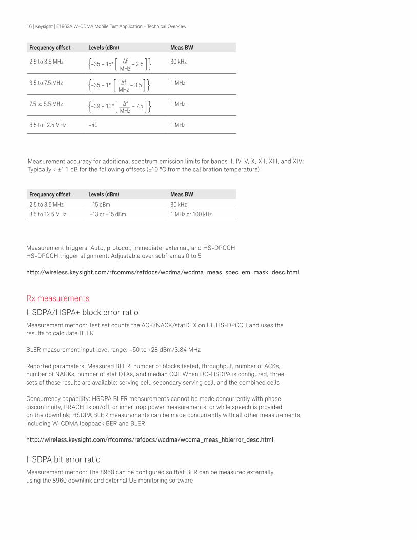
Frequency offset Levels (dBm) Meas BW
2.5 to 3.5 MHz {–35 – 15* [ Δf – 2.5 ] } MHz
30 kHz
3.5 to 7.5 MHz {–35 – 1* [ Δf – 3.5 ] } MHz
1 MHz
7.5 to 8.5 MHz {–39 – 10* [ Δf – 7.5 ] } MHz
1 MHz
8.5 to 12.5 MHz –49 1 MHz
Frequency offset Levels (dBm) Meas BW
2.5 to 3.5 MHz –15 dBm 30 kHz
3.5 to 12.5 MHz –13 or –15 dBm 1 MHz or 100 kHz
Measurement accuracy for additional spectrum emission limits for bands II, IV, V, X, XII, XIII, and XIV: Typically < ±1.1 dB for the following offsets (±10 °C from the calibration temperature)
Measurement triggers: Auto, protocol, immediate, external, and HS-DPCCHHS-DPCCH trigger alignment: Adjustable over subframes 0 to 5 http://wireless.keysight.com/rfcomms/refdocs/wcdma/wcdma_meas_spec_em_mask_desc.html
Rx measurements
HSDPA/HSPA+ block error ratio
Measurement method: Test set counts the ACK/NACK/statDTX on UE HS-DPCCH and uses the results to calculate BLER BLER measurement input level range: –50 to +28 dBm/3.84 MHz Reported parameters: Measured BLER, number of blocks tested, throughput, number of ACKs, number of NACKs, number of stat DTXs, and median CQI. When DC-HSDPA is configured, three sets of these results are available: serving cell, secondary serving cell, and the combined cells Concurrency capability: HSDPA BLER measurements cannot be made concurrently with phase discontinuity, PRACH Tx on/off, or inner loop power measurements, or while speech is provided on the downlink; HSDPA BLER measurements can be made concurrently with all other measurements, including W-CDMA loopback BER and BLER http://wireless.keysight.com/rfcomms/refdocs/wcdma/wcdma_meas_hblerror_desc.html
HSDPA bit error ratioMeasurement method: The 8960 can be configured so that BER can be measured externally using the 8960 downlink and external UE monitoring software

17 | Keysight | E1963A W-CDMA Mobile Test Application - Technical Overview
W-CDMA Specifications
Call connection types
End-to-end video conferencing (Option 401) Loop back video conferencing (Option 402)
The E1963A, when configured as a two-instrument system, provides true H324 call setup with live video and audio from both mobile devices. With only one E5515C, loop back video call can be setup with Option 402.
Validate compatibility by testing interoperability between your mobile and the competitor models offered for the same network.
– Complete call setup, mobile origination, and mobile release – 64 k circuit-switched UDI channel – H324 call setup
http://wireless.keysight.com/rfcomms/refdocs/wcdma/wcdma_gen_call_video_call.html
AMR voiceStandard voice call with audio loopback for a quick check of voice functionality for 12.2 k rate; also many more AMR rates, such as 4.75, 5.15, 5.9, 6.7, 7.4, 7.95, 10.2, and 12.2 k
– UE and BS origination 12.2 k – UE and BS release
http://wireless.keysight.com/rfcomms/refdocs/wcdma/wcdma_gen_bse_amrvoice.html
FDD test modeFDD test mode allows you to test the parametric performance of your UE’s transmitter and receiver without call processing. In FDD test mode, the test set does not send signaling information on the downlink. Rather, it continuously generates a downlink signal and searches for a corresponding uplink signal. The UE must synchronize to the downlink signal and send an appropriate uplink signal, which the test set uses to measure the UE’s transmitter and receiver performance. Any changes to the UE configuration must be accomplished by directly sending commands to the UE from a system controller through a proprietary digital interface.
http://wireless.keysight.com/rfcomms/refdocs/wcdma/wcdma_gen_bse_fddtest.html
RB test modeFast conformance test calls with significant configuration control and testing capabilities
BS origination and release
Symmetrical configuration: W-CDMA modes support symmetrical RMCs at 12.2, 64, 144, and 384 k rates. These symmetrical RMCs are typically used for transmitter testing and receiver testing user BER (via loopback type 1) or BLER (via loopback type 2)
Asymmetric configuration: The asymmetrical RMCs use either a 12.2 or a 64 k channel on the uplink. The primary purpose of the symmetrical RMCs is to provide a way to make a BLER measurement by counting retransmission requests that the UE sends. There is no need for data loopback in this mode
http://wireless.keysight.com/rfcomms/refdocs/wcdma/wcdma_gen_bse_rbtest_setup.html

18 | Keysight | E1963A W-CDMA Mobile Test Application - Technical Overview
Inter-system handoverDual-mode functionality is required for most W-CDMA phones, as GSM is an integral part in the majority of devices shipping today. Inter-system handovers provide a means to validate dual-mode performance at your desk instead of roaming on a real network. When operated in conjunction with compressed mode, this feature can very closely emulate the basics of a real handover as made on the network.
– Blind handovers from W-CDMA to GSM – Configurable landing GSM cell – Test control to GSM voice – W-CDMA AMR voice to GSM voice
http://wireless.keysight.com/rfcomms/refdocs/wcdma/wcdma_gen_call_handoffs.html
W-CDMA RF generator
W-CDMA channels
RF generator level accuracy is derived from the 99th percentile observations with 95% confidence (corresponds to an expanded uncertainty with a 95% confidence (k=2)) at ambient conditions, then qualified to include the environmental effects of temperature and humidity.
RF IN/OUT cell power absolute output level accuracyAWGN off:
– < ±1.1 dB (typically < ±0.65 dB), at –109 to –15 dBm/3.84 MHz and – < 2300 MHz – < ±1.5 dB (typically < ±1.0 dB), at –109 to –15 dBm/3.84 MHz and ≥ 2300 MHz
Channel (spread factor) Default assignment Alternate choices
CPICH (256) 0 –
P-CCPCH (256) 1 –
S-CCPCH (64) 7 All these channel codes are settable within respective available code range
AICH (256) 10
PICH (256) 16
DPCH, 3.4 kbps SRB (256) 12
DPCH, 12.2 kbps RMC (128) 9
DPCH, 64 kbps RMC (32) 6
DPCH, 144 kbps RMC (16) 12
DPCH, 384 kbps RMC (8) 6
OCNS(test model 1) (128)
Spreading factor of 128 at the fixed OVSF codes of 2, 11, 17, 23, 31, 38, 47, 55, 62, 69, 78, 85, 94, 113, 119, 125
Channel code issettable withinavailable code range

19 | Keysight | E1963A W-CDMA Mobile Test Application - Technical Overview
RF IN/OUT composite signal absolute output level accuracyAWGN on:
– < ±1.2 dB, at –80 to –20 dBm/3.84 MHz and < 2300 MHz, typically < ±0.75 dB, over –109 to –20 dBm/3.84 MHz and < 2300 MHz
– < ±1.6 dB, at –80 to –20 dBm/3.84 MHz and ≥ 2300 MHz typically < ±1.1 dB, at –109 to –20 dBm/3.84 MHz and ≥ 2300 MHz
RF OUT ONLY cell power absolute output level accuracyAWGN off:
– < ±1.1 dB, at –109 to –7 dBm/3.84 MHz and < 2300 MHz typically < ±0.65 dB, –109 to –15 dBm/3.84 MHz
– < ±1.5 dB, typically < ±1.0 dB, at –109 to –15 dBm/3.84 MHz and ≥ 2300 MHz
RF OUT ONLY composite signal absolute output level accuracyAWGN on:
– < ±1.2 dB, at –80 to –12 dBm/3.84 MHz and < 2300 MHz typically < ±0.75 dB, at –109 to –20 dBm/3.84 MHz and < 2300 MHz
– < ±1.6 dB, at –80 to –20 dBm/3.84 MHz and ≥ 2300 MHz typically < ±1.1 dB, at –109 to –20 dBm/3.84 MHz and ≥ 2300 MHz
Common pilot channel relative level: –20 to 0 dB
Primary sync channel relative level: Always the same as P-CCPCH
Secondary sync channel relative level: Always the same as P-CCPCH
Primary CCPCH relative level: –20 to 0 dB
DPCH relative level: Settable from –30 to 0 dB with 0.01 dB resolution
PICH relative level: –20 to 0 dB
Downlink CDMA modulationModulation type: QPSK per 3GPP standard
Residual EVM: < 10%, typically < 3%
Carrier feed through: < –25 dBc, typically < –35 dBc, nominal ambient performance: < –45 dBc
OCNS – orthogonal channel noise sourceComposed of 16 channels per Table E.3.6 in Annex E of 3GPP 34.121
OCNS channel relative level range: Automatically calculated from other code channel relative levels to provide the set CDMA cell power
Relative CDMA channel level accuracy: < ±0.2 dB
http://wireless.keysight.com/rfcomms/refdocs/wcdma/wcdma_gen_bse_gen_info.html_BCGCBAHE

20 | Keysight | E1963A W-CDMA Mobile Test Application - Technical Overview
W-CDMA RF analyzer (measurements only)Real-time demodulation of: Uplink DPCH
W-CDMA Tx measurements
Thermal power measurement
Measurement bandwidth: > 5 MHz; if other signals are present outside of this frequency range, reduced measurement accuracy will result
Measurement data capture period: 10 ms
Measurement range: –10 to +28 dBm; usable to –20 dBm with degraded accuracy
Measurement level ranging: Auto
Auto zero function: Measurement automatically zeros the thermal power meter (no user control)
Measurement accuracy: (With 10 internal averages)
– 375 to 500 MHz < ±6.6%, typically < ±3.0% – 698 to 1000 MHz < ±6.0%, typically < ±3.0% – 1400 to 1500 MHz < ±7.2%, typically < ±3.7% – 1700 to 2000 MHz < ±7.2%, typically < ±3.7% – 2480 to 2580 MHz < ±8.7%, typically < ±3.7%
Temperature range: +20 to +55 °C http://wireless.keysight.com/rfcomms/refdocs/wcdma/wcdma_meas_thermalpow_desc.html
Channel power measurementMeasurement bandwidth
RRC filter off: Measured with a bandwidth greater than (1 + a) x chip rate, where a = 0.22 and chip rate = 3.84 Mcps
RRC filter on: Measured with a filter that has a root-raised cosine (RRC) filter response with roll-off a = 0.22 and a bandwidth equal to the chip rate (3.84 MHz bandwidth centered on the active uplink channel)
Measurement range: –61 to +28 dBm/3.84 MHz
Measurement interval: Settable from 0.01 to 12 ms
Measurement triggers: Auto, immediate, protocol, external, and RF rise
Measurement accuracy (at +10 °C from the calibration temperature):
– < ±1.0 dB (typically < ±0.5 dB) for measurement intervals of 333 μs to 12 ms over 698 to 1024 MHz, 1400 to 1500 MHz, and 1700 to 2000 MHz
– < ±1.0 dB (typically < ±0.55 dB) for measurement intervals of 333 μs to 12 ms over 2480 to 2580 MHz
– < ±1.0 dB (typically < ±0.55 dB) for measurement intervals of 67 to < 333 μs over 698 to 1024 MHz, 1400 to 1500 MHz, and 1700 to 2000 MHz
Temperature range: +20 to +55 °C
Temperature drift: Typically 0.1 dB per 10 °C temperature change
http://wireless.keysight.com/rfcomms/refdocs/wcdma/wcdma_meas_chanpow_desc.html

21 | Keysight | E1963A W-CDMA Mobile Test Application - Technical Overview
Fast device tune measurementDescription: Allows simultaneous calibration of a device’s Tx output power and Rx input level across level and frequency in a single sweep (per frequency band). The device must operate in a test mode which forces it to transmit a predefined series of power steps at various uplink frequencies, and also forces it to simultaneously tune its receiver to perform measurements (such as RSSI) of the test set’s signal at various downlink frequencies and power levels
Input frequency ranges: 698 to 1000 MHz, 1400 to 1500 MHz, 1700 to 1990 MHz, and 2480 to 2580 MHz
Tx power measurement input level range: –61 to +28 dBm/3.84 MHz
Tx power measurement level change between adjacent steps:
– < 20 dB for 20 ms step size – < 10 dB for 10 ms step size
Tx power measurement accuracy (at +10 degrees from calibration temperature): < ±1.0 dB
Rx level output range at RF IN/OUT port: –109 to –15 dBm/3.84 MHz
Rx level output range at RF OUT ONLY port: –109 to –7 dBm/3.84 MHz
Rx level change between adjacent steps: < 20 dB
Rx level accuracy with W-CDMA modulation: < ±1.1 dB
Rx level setting: < 5.1 ms to be within 0.1 dB
Concurrency capabilities: Fast device tune measurements cannot be made concurrently with other measurements
http://wireless.keysight.com/rfcomms/refdocs/wcdma/wcdma_meas_cfdtune_desc.html
UE TXsequence
Tx power step
20 ms
667 μs
Frequencyre-tune
UE Tx power sequence
Ranging
6.33 ms
Pre-set interval
13 ms
Measurement period
UE TXsequence
Tx power step
10 ms
667 μs
Frequencyre-tune
UE Tx power sequence
Ranging
3.16 ms
Pre-set interval
6.17 ms
Measurement period
UE RXsequence
Rx power step
20 msFrequencyre-tune
UE Rx power sequence
Settling
5.1 ms
RSSI measurement interval
14.9 ms
UE RXsequence
Rx power step
10 msFrequencyre-tune
UE Rx power sequence
Settling
5.1 ms
RSSI measurement interval
4.9 ms

22 | Keysight | E1963A W-CDMA Mobile Test Application - Technical Overview
Waveform quality measurementWaveform quality measurement: Composite EVM
Measurement format: HPSK
Measurement chip rate: 3.84 Mcps
Input level range: –25 to +28 dBm/3.84 MHz
Measurement range: ≤ 35% EVM
Measurement interval: 1 timeslot
Measurement accuracy (including the effects of residual EVM):
EVM measurement accuracy:
– < 2.8% rms (typically < 2.4% rms) for UE EVM ≥ 1% rms, ≤ 2200 MHz – < 3.2% rms (typically < 2.8% rms) for UE EVM ≥ 1% rms, 2300 to 2580 MHz
Other reported parameters with EVM:
– Frequency error – Magnitude error – Phase error – Origin offset – Timing error – Peak code domain error
Frequency error measurement range: ±1 kHz
EVM
mea
urem
ent
unce
rtai
nty
(acc
urac
y)
EU EVM (% rms)
3.5
3.0
2.5
2.0
1.5
1.0
0.5
0.0
0 2 4 6 8 10 12 14 16
Band VII All other bands
Typical UEEVM range

23 | Keysight | E1963A W-CDMA Mobile Test Application - Technical OverviewFr
eque
ncy
erro
r m
easu
rem
ent
unce
rtai
nty
(Hz)
UE EVM (% rms)
505
504
503
502
501
500
0 2 4 6 8 10 12 14 16
Typical UEEVM range
Residual frequency error: < ± (5 Hz + timebase accuracy)
Peak code domain error accuracy: < ±0.3 dB for levels > –25 dB
Timing error measurement range: ± 10 μs
Timing error measurement accuracy: < ±0.5 chips (±130 ns)
Temperature range: +20 to +55 °C
http://wireless.keysight.com/rfcomms/refdocs/wcdma/wcdma_meas_wfrmqual_desc.html
IQ tuningAll measurements found in the waveform quality measurement are also available in the IQ tuning measurement; the specifications are the same in both measurements
http://wireless.keysight.com/rfcomms/refdocs/wcdma/wcdma_meas_iqtuning_desc.html
Adjacent channel leakage ratio (ACLR)Measurement method: Ratio of the filtered mean transmitted power to the filtered mean power in an adjacent channel; both the transmitted and the adjacent channel powers are measured with a filter that has a RRC response with roll-off a = 0.22 and a band width equal to the chip rate
Input power level range: +5 to +28 dBm/3.84 MHz
Input frequency ranges: 698 to 1000 MHz, 1400 to 1500 MHz, 1700 to 2000 MHz, and 2480 to 2580 MHz
Measurement level ranging: Auto
Measurement triggers: Auto, protocol, immediate, and external
Measurement interval: 1 timeslot
Measurement result: dBc relative to in-channel transmitted power
Measurement accuracy: < ±0.8 dB (typically < ±0.5 dB), including the effects of the residual floor, for measurements at –33 dBc at ±5 MHz offsets and –43 dBc at ±10 MHz offsets, and ±10 °C from the calibration temperature
Residual ACLR floor: < –53 dBc for ±5 MHz offsets, < –63 dBc for ±10 MHz offsets
Temperature range: +20 to +55 °C
http://wireless.keysight.com/rfcomms/refdocs/wcdma/wcdma_meas_aclr_desc.html
24 | Keysight | E1963A W-CDMA Mobile Test Application - Technical Overview
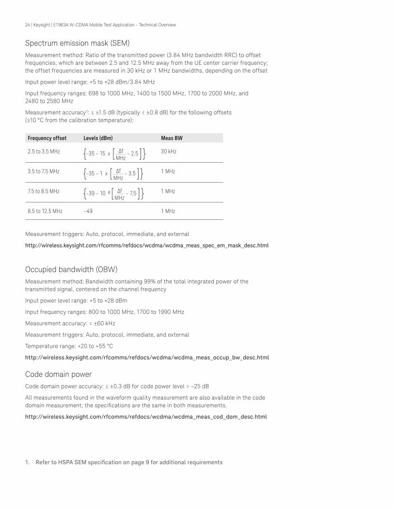
Spectrum emission mask (SEM)Measurement method: Ratio of the transmitted power (3.84 MHz bandwidth RRC) to offset frequencies, which are between 2.5 and 12.5 MHz away from the UE center carrier frequency; the offset frequencies are measured in 30 kHz or 1 MHz bandwidths, depending on the offset
Input power level range: +5 to +28 dBm/3.84 MHz
Input frequency ranges: 698 to 1000 MHz, 1400 to 1500 MHz, 1700 to 2000 MHz, and 2480 to 2580 MHz
Measurement accuracy1: ≤ ±1.5 dB (typically < ±0.8 dB) for the following offsets (±10 °C from the calibration temperature):
Measurement triggers: Auto, protocol, immediate, and external
http://wireless.keysight.com/rfcomms/refdocs/wcdma/wcdma_meas_spec_em_mask_desc.html
Occupied bandwidth (OBW)Measurement method: Bandwidth containing 99% of the total integrated power of the transmitted signal, centered on the channel frequency
Input power level range: +5 to +28 dBm
Input frequency ranges: 800 to 1000 MHz, 1700 to 1990 MHz
Measurement accuracy: < ±60 kHz
Measurement triggers: Auto, protocol, immediate, and external
Temperature range: +20 to +55 °C
http://wireless.keysight.com/rfcomms/refdocs/wcdma/wcdma_meas_occup_bw_desc.html
Code domain powerCode domain power accuracy: ≤ ±0.3 dB for code power level > –25 dB
All measurements found in the waveform quality measurement are also available in the code domain measurement; the specifications are the same in both measurements.
http://wireless.keysight.com/rfcomms/refdocs/wcdma/wcdma_meas_cod_dom_desc.html
1. Refer to HSPA SEM specification on page 9 for additional requirements
Frequency offset Levels (dBm) Meas BW
2.5 to 3.5 MHz {–35 – 15 x [ Δf – 2.5 ] } MHz
30 kHz
3.5 to 7.5 MHz {–35 – 1 x [ Δf – 3.5 ] } MHz
1 MHz
7.5 to 8.5 MHz {–39 – 10 x [ Δf – 7.5 ] } MHz
1 MHz
8.5 to 12.5 MHz –49 1 MHz

25 | Keysight | E1963A W-CDMA Mobile Test Application - Technical Overview
PRACH transmit on/off powerMeasurement method: The measure of the ON power of the PRACH preamble burst, along with the OFF power preceding the burst and the OFF power following the burst
Input power level range:
– ON power: –40 to +28 dBm/3.84 MHz – OFF power: –61 to –55 dBm/3.84 MHz
Input frequency ranges: 800 to 1000 MHz, 1700 to 1990 MHz
Measurement accuracy: < ±1.0 dB (typically < ±0.5 dB) within ±10 °C from the calibration temperature
Nominal trigger range: Expected power ±9 dB
Temperature range: +20 to +55 °C
Concurrency capabilities: PRACH Tx on/off measurements cannot be made concurrently with other measurements
http://wireless.keysight.com/rfcomms/refdocs/wcdma/wcdma_meas_oopow_desc.html
Phase discontinuityMeasurement method: The measured results include the phase discontinuity (defined as the phase difference of adjacent timeslots) as well as all waveform quality results for each timeslot
Input power level range:
– Phase discontinuity: –61 to +28 dBm/3.84 MHz – Other measurements: –25 to +28 dBm/3.84 MHz
Input frequency ranges: 800 to 1000 MHz, 1700 to 1990 MHz
Phase discontinuity range: ±180°
EVM range: 0 to 35% rms
Phase discontinuity measurement accuracy:
– < ±2.4° (typically < ±1.7°) for input levels of –25 to +28 dBm/3.84 MHz – < ±2.6° (typically < ±1.9°) for input levels of –51 to < –25 dBm/3.84 MHz
Other reported parameters with phase discontinuity: All measurements found in the waveform quality measurement are also available; the specifications are the same in both measurements, including the input power range of the waveform quality measurement
Measurement interval: 617 μs (= 1 timeslot (667 μs) – 25 μs transient periods at either side of the nominal timeslot boundaries)
Measurement triggers: Protocol and external
Temperature range: +20 to +55 °C
Concurrency capabilities: Phase discontinuity measurements cannot be made concurrently with other measurements
http://wireless.keysight.com/rfcomms/refdocs/wcdma/wcdma_meas_wpdiscon_desc.html

26 | Keysight | E1963A W-CDMA Mobile Test Application - Technical Overview
Tx dynamic power measurementMeasurement method: Captures a user-defined trace consisting of 20, 40, or 80 ms duration power steps with user-defined step size produced by a test mode in the UE under test; measures the total power in a 3.84 MHz bandwidth centered on the active uplink center frequency in each step period
Measurement data capture period: 667 μs
Measurement trigger: Tx signal output by the mobile station must provide a pulse (off-on-off) followed by the stepped power burst beginning at the user specified output power
Measurement range: –61 to +28 dBm/3.84 MHz
Measurement level ranging: None; user must set the test set’s receiver power control field to manual and set the receiver power to the expected full power of the power sweep produced by the UE
Measurement accuracy: (Calibrated against average power and within ±10 degrees of calibration temperature; calibration must occur between 20 to 55 °C);
– < ±1.0 dB (typically < ±0.5 dB) over 15 to 55 °C, 698 to 1000 MHz, 1400 to 1500 MHz and 1700 to 2000 MHz
– < ±1.0 dB (typically < ±0.55 dB) over 15 to 55 °C and 2480 to 2580 MHz Measurement step duration (time): 20, 40, or 80 ms
Measurement step size: –90.00 to –0.01 dB
Measurement number of steps: 0 to 99
Measurement result: A graph displaying the discrete power at each power step along with numeric power results for each step
Measurement graphical controls: Marker on/off with position, trace start step, trace span, and return to default scale
Concurrency capabilities: Tx dynamic power measurements cannot be made concurrently with other measurements
Calibrate function: Uses the channel power calibration function
http://wireless.keysight.com/rfcomms/refdocs/wcdma/wcdma_meas_wtdpower_desc.html
Triggerpulse
User specifiedmaximum power
Step size
Step duration

27 | Keysight | E1963A W-CDMA Mobile Test Application - Technical Overview
Extended range dynamic power measurementMeasurement method: Allows measurement of a UE’s transmitter output power across its entire dynamic power (up to 90 dB) in one measurement cycle. This measurement requires the UE be put into a test mode which forces it to transmit up to two power sequences and analyzes the resulting UE output power using the test set
Measurement bandwidth: Selectable RRC filter on or off
Measurement range: –61 dBm to +28 dBm/3.84 MHz
Measurement accuracy:
– ±1.0 dB (typically ±0.5 dB), at top 25 dB of dynamic range – ±1.0 dB (typically ±0.55 dB), at top 30 dB of dynamic range – ±1.0 dB (typically ±0.55 dB), at top 35 dB of dynamic range with RRC filter on
Measurement trigger: RF rise, external
Temperature range: +20 to +55°C
Temperature drift: Typically < 0.1 dB per 10 °C temperature change
RF input
Expected power setting =Maximum power to be encountered in the first sequence
Step length= 1 timeslot
Re-range
period= 15 timeslots
Second sequence expectedpower setting=
Maximum power to beencountered in the second sequence
Firstsequence
Secondsequence
Re-rangeperiod
Time
Start point
Measurement interval = ½ timeslot
RF rise> 20 dB

28 | Keysight | E1963A W-CDMA Mobile Test Application - Technical Overview
Inner loop powerMeasurement method: Inner loop power control in the uplink is the ability of the UE transmitter to adjust its output power in accordance with one or more TPC commands received in the downlink; the absolute and relative power is reported for each power step
Measurement range: –61 to +28 dBm/3.84 MHz
Input frequency ranges: 800 to 1000 MHz, 1700 to 1990 MHz
Measurement accuracy: Absolute power: < ±1.0 dB, typically < ±0.5 dB Relative power:
– < ±0.1 dB for range ≤ 1.5 dB (–51 to +28 dBm/3.84 MHz) < ±0.184 dB for range ≤ 1.5 dB (–61 to –51 dBm/3.84 MHz)
– < ±0.15 dB for range ≤ 3 dB (–51 to +28 dBm/3.84 MHz) – < ±0.174 dB for range ≤ 3 dB (–61 to –51 dBm/3.84 MHz) – < ±0.3 dB for range ≤ 26 dB (–61 to +28 dBm/3.84 MHz)
Temperature range: +20 to +55 °C
Temperature drift: Typically < 0.1 dB per 10 °C temperature change for the absolute power measurements; typically < 0.025, 0.02, and 0.05 dB over +20 to +55 °C temperature range for relative power ranges of 1.5, 3, and 26 dB respectively
Concurrency capabilities: Inner loop power measurements cannot be made concurrently with other measurements
http://wireless.keysight.com/rfcomms/refdocs/wcdma/wcdma_meas_ilpow_desc.html
Dynamic power analysisMeasurement method: Graphical display of a series of channel power measurement for a user-defined number of steps and step lengths
Input level range: –61 to +28 dBm/3.84 MHz
Data capture range: Combination of number of steps and step length cannot exceed 58.26 ms
Measurement bandwidth: Selectable RRC filter on or off
Measurement interval: Settable from 0.01 to 12 ms (must be less than or equal to the step length)

29 | Keysight | E1963A W-CDMA Mobile Test Application - Technical Overview
Measurement accuracy: (At +10 °C from calibration temperature with measurement interval 333 μs to 12 ms):
Measurement triggers: External, RF rise
http://wireless.keysight.com/rfcomms/refdocs/wcdma/wcdma_meas_wdpanalysis_desc.html
Rx measurements
Loopback bit error ratio
Measurement method: Data loopback (mode 1 in 3GPP TS 34.109)
BER measurement input level range: –50 to +28 dBm/3.84 MHz
Reported parameters:
– Intermediate results: Measured bit error ratio, number of errors, number of bits tested, uplink missing blocks, uplink CRC errors, and loopback delay
– Final results: Measured BER, number of errors, number of bits tested, uplink missing blocks, CRC errors, and loopback delay
Concurrency capabilities: BER measurements cannot be made concurrently with BLER, phase discontinuity, PRACH Tx on/off, or inner loop power measurements, or while speech is provided on the downlink; loopback BER measurements can be made concurrently with all other measurements
http://wireless.keysight.com/rfcomms/refdocs/wcdma/wcdma_meas_loopber_desc.html
Block error ratioMeasurement method: The UE is configured to loop back the data bits and the CRC bits from the downlink transport blocks into the uplink transport blocks on the DPCH; a comparison is made in the test set by generating a CRC using the data bits received on the uplink and comparing the calculated CRC against the CRC received in the uplink transport block
BLER measurement input level range: –50 to +28 dBm/3.84 MHz
Reported parameters: Measured BLER, block error count, number of blocks tested, and uplink missing blocks
Concurrency capabilities: BLER measurements cannot be made concurrently with loopback BER, phase discontinuity, PRACH Tx on/off, or inner loop power measurements, or while speech is provided on the downlink; BLER measurements can be made concurrently with all other measurements
http://wireless.keysight.com/rfcomms/refdocs/wcdma/wcdma_meas_wblerror_desc.html
Input level range Measurement accuracy Frequency range
≤ 25 dB < ±1.0 dB, typically < ±0.5 dB< ±1.0 dB, typically < ±0.55 dB
800 to 1000 MHz 1700 to 2000 MHz
2480 to 2580 MHz
≤ 35 dB < ±1.0 dB,typically < ±0.55 dB< ±1.0 dB,typically < ±0.6 dB
800 to 1000 MHz1700 to 2000 MHz 2480 to 2580 MHz
≤ 40 dBwith RRC filter on
< ±1.0 dB,typically < ±0.55 dB< ±1.0 dB,typically < ±0.7 dB
800 to 1000 MHz1700 to 2000 MHz 2480 to 2580 MHz

30 | Keysight | E1963A W-CDMA Mobile Test Application - Technical Overview
HSPA and W-CDMA Common Technical Specifications
RF generator
Downlink frequency
Frequency/channel setting: By channel number or MHz (test mode only)
Frequency accuracy: Same as timebase reference
Frequency setting resolution: 1 Hz
http://wireless.keysight.com/rfcomms/refdocs/wcdma/wcdma_gen_bse_dl_chan_num.html
Frequency ranges (MHz)
Band I (IMT-2000) 2112.4 to 2167.6
Band II (US PCS) 1932.4 to 1987.6
Band III (DCS/PCS) 1807.4 to 1877.6
Band IV 2112.4 to 2152.6
Band V (US Cellular) 871.5 to 887.5
Band VI (Japan 800) 877.4 to 882.6
Band VII (UMTS 2600) 2622.4 to 2687.6
Band VIII (UMTS 900) 927.4 to 957.6
Band IX (UMTS 1700) 1847.4 to 1877.4
Band X (UMTS Extended) 2112.4 to 2167.6
Band XI (UMTS 1500) 1478.4 to 1498.4
Band XII (UMTS 700) 728 to 746
Band XIII (UMTS 700) 746 to 756
Band XIV (UMTS 700) 758 to 768
Band XIX 877.4 to 887.6
Band XX 793.4 to 818.6
Band XXI 1498.4 to 1508.4

31 | Keysight | E1963A W-CDMA Mobile Test Application - Technical Overview
Downlink amplitudeOutput port control: Control of RF source routing to either the RF IN/OUT port or the RF OUT ONLY port
Composite signal level: The sum of the user-set values of the cell power and the AWGN source measured in a root-raised cosine filter response with a roll off a = 0.22 and a 3.84 MHz BW; if the cell power is ON, the AWGN level must be set to within –20 dB to +10 dB of the cell power. Note: The composite signal level is not settable, however it is reported by the test set
RF IN/OUT cell power output range: –115 to –13 dBm/3.84 MHz
RF IN/OUT AWGN signal output level range: –115 to –20 dBm/3.84 MHz
RF IN/OUT VSWR:
– < 1.14:1, 400 to 500, 700 to 1000 MHz – < 1.2:1, 1700 to 2000 MHz – < 1.4:1, 2000 to 2700 MHz
RF IN/OUT reverse power: +37 dBm peak (5 W peak)
RF OUT ONLY cell power output range: –115 to –5 dBm/3.84 MHz
RF OUT ONLY reverse power: +24 dBm peak (250 mW peak)
Measurement calibrate function: Calibrates the channel power, ACLR, SEM, waveform quality, OBW, and code domain measurements over the specified frequency range of the test set against the thermal power measurement, no external cabling is required to perform this function
Measurement calibration time: < 180 seconds
Measurement calibration temperature range: Valid ±10 °C from previously calibrated temperature
AWGN channel relative level range: Settable to –20 dB to +10 dB relative to the user-set CDMA cell power with 0.01 dB resolution

32 | Keysight | E1963A W-CDMA Mobile Test Application - Technical Overview
RF analyzer
Frequency/Channel setting: By channel number or MHz (test mode only)
http://wireless.keysight.com/rfcomms/refdocs/wcdma/wcdma_gen_bse_ul_chan_num.html
Input level setting range: –70 to +30 dBm/3.84 MHz
Receiver ranging:
– Auto (Active closed loop power control): The test set uses TPC commands to the UE to adjust its transmit power as needed to achieve the “UE Target Power”
– Manual mode: User enters expected power; provides calibrated results if actual power is within ±9 dB of the user-entered level
Demodulation chip rate: 3.84 Mcps
Maximum input level: +37 dBm peak (5 W peak)
Amplitude scaling: Settable from 0.1 to 20 dB/division in 0.1 dB steps
Measurement input frequency ranges
698 to 1000 MHz
1400 to 1500 MHz
1700 to 1990 MHz
2480 to 2580 MHz
Frequency ranges for uplink channels (MHz)
Band I (IMT-2000) 1922.4 to 1977.6
Band II (US PCS) 1852.4 to 1907.6
Band III (DCS/PCS) 1712.4 to 1782.6
Band IV 1712.4 to 1752.6
Band V (US Cellular) 826.4 to 846.6
Band VI (Japan 800) 832.4 to 837.6
Band VII (UMTS 2600) 2502.4 to 2567.6
Band VIII (UMTS 900) 882.4 to 912.6
Band IX (UMTS 1700) 1752.4 to 1782.4
Band X (UMTS Extended) 1712.4 to 1767.6
Band XI (UMTS 1500) 1430.4 to 1450.4
Band XII (UMTS 700) 698 to 716
Band XIII (UMTS 700) 777 to 787
Band XIV (UMTS 700) 788 to 798
Band XIX 832.4 to 842.6
Band XX 834.4 to 859.6
Band XXI 1450.4 to 1460.4

33 | Keysight | E1963A W-CDMA Mobile Test Application - Technical Overview
Trigger source: Immediate, protocol, RF rise, external, auto
Trigger delay: Settable between ±50 ms
Peak threshold: Settable from –120 to +37 dBm
Peak excursion: Settable from 1.2 to 100 dB
Trace functions: Clear write, max hold, min hold
Detector type: Peak or sample
Tx measurements
Spectrum monitor
Operating modes: Active cell and test mode
Measurement modes: Swept mode or zero span
Frequency ranges: Although the spectrum monitor is available at any frequency supported by the test set, specifications apply only inside of the calibrated bands: 698 to 1000 MHz, 1400 to 1500 MHz, 1700 to 2000 MHz, and 2480 to 2580 MHz
Frequency spans, resolution bandwidth range: Span and RBW can be independently set, except for zero span; zero span can only be set with the RBW combinations shown below
(Specifications only apply for span and RBW combinations shown in the following table):
RBW filter types: Flattop in swept mode, Gaussian in zero span
Zero span sweep time: Settable from 50 μs to 70 ms
Zero span offset time: Settable from 0 to 10 s
Reference level range: Settable from –50 to +37 dBm or automatically determined
Span RBW Displayed dynamic range
100 MHz 5 MHz 50 dB
80 MHz 1 MHz 55 dB
40 MHz 300 kHz 60 dB
20 MHz 100 kHz 65 dB
12 MHz 100 kHz 65 dB
10 MHz 100 kHz 65 dB
5 MHz 30 kHz 70 dB
4 MHz 30 kHz 70 dB
2.5 MHz 10 kHz 75 dB
1.25 MHz 3 kHz 80 dB
500 kHz 1 kHz 80 dB
125 kHz 300 Hz 80 dB
0 1 MHz 55 dB
0 300 kHz 60 dB
0 100 kHz 65 dB

34 | Keysight | E1963A W-CDMA Mobile Test Application - Technical Overview
Averaging capabilities: Settable between 1 and 999, or off
Marker functions: Three independent markers with modes of normal, delta, and off; operations are peak search, marker to expected power, and marker to expected frequency
Concurrency capabilities: Spectrum monitor analysis can be performed concurrently with all measurements
Supplemental characteristics
Typical level accuracy
– < ±2 dB for signals within 50 dB of a reference level > –10 dBm and RBW < 5 MHz – < ±2 dB for signals within 30 dB of a reference level < –10 dBm and RBW = 5 MHz
using 5 averages, – < ±3.5 dB for signals > –70 dBm and within 50 dB of a reference level < –10 dBm
with RBW < 5 MHz Displayed average noise level: < –90 dBm for reference level of –40 dBm and 30 kHz bandwidth
Typical residual responses: < –70 dB with input terminated, reference level of –10 dBm and RF generator power < –80 dBm
Typical spurious responses: < –50 dBc with expected frequency tuned to carrier, carrier > 420 MHz, signal and reference level at –10 dBm and all spectral components within 100 MHz of carrier
Frequency resolution: 1 Hz
Marker amplitude resolution: 0.01 dB
http://wireless.keysight.com/rfcomms/refdocs/wcdma/wcdma_meas_smonitor_desc.html
Audio generator
Frequency
Operating range: 100 Hz to 20 kHz, typically 1 Hz to 20 kHz
Accuracy: Same as timebase reference
Frequency resolution: 0.1 Hz
Output level (from AUDIO OUTPUT connector)Ranges: 0 to 1 V peak, 1 to 9 V peak (into > 600 ohms)
Accuracy: < ±(1.5% of setting + resolution) when output is DC coupled
Distortion: < 0.1% for 0.2 to 9 V peak into > 600 ohms
Coupling mode: Selectable as DC or AC (5 μF in series with output)
Typical maximum output current: 100 mA peak into 8 ohms
Typical output impedance: < 1.5 ohms at 1 kHz when output is DC coupled
Typical DC offset (when output is DC coupled):
– < 1 mV peak for 0 to 1 V peak – < 10 mV peak for 1 to 9 V peak
Output level resolution: < 0.5 mV for 0 to 1 V peak output, < 5.0 mV for 1 to 9 V peak output
http://wireless.keysight.com/rfcomms/refdocs/wcdma/wcdma_conf_audio_out.html_BJFBAIEH
35 | Keysight | E1963A W-CDMA Mobile Test Application - Technical Overview
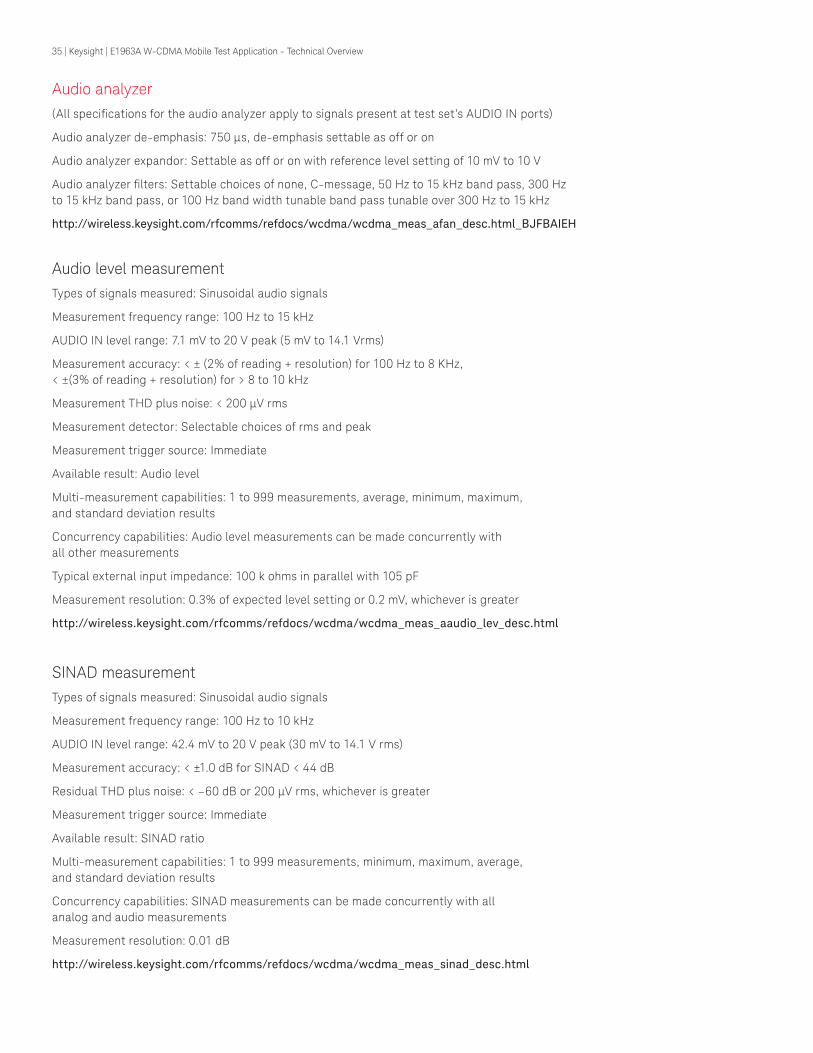
Audio analyzer(All specifications for the audio analyzer apply to signals present at test set’s AUDIO IN ports)
Audio analyzer de-emphasis: 750 μs, de-emphasis settable as off or on
Audio analyzer expandor: Settable as off or on with reference level setting of 10 mV to 10 V
Audio analyzer filters: Settable choices of none, C-message, 50 Hz to 15 kHz band pass, 300 Hz to 15 kHz band pass, or 100 Hz band width tunable band pass tunable over 300 Hz to 15 kHz
http://wireless.keysight.com/rfcomms/refdocs/wcdma/wcdma_meas_afan_desc.html_BJFBAIEH
Audio level measurementTypes of signals measured: Sinusoidal audio signals
Measurement frequency range: 100 Hz to 15 kHz
AUDIO IN level range: 7.1 mV to 20 V peak (5 mV to 14.1 Vrms)
Measurement accuracy: < ± (2% of reading + resolution) for 100 Hz to 8 KHz, < ±(3% of reading + resolution) for > 8 to 10 kHz
Measurement THD plus noise: < 200 μV rms
Measurement detector: Selectable choices of rms and peak
Measurement trigger source: Immediate
Available result: Audio level
Multi-measurement capabilities: 1 to 999 measurements, average, minimum, maximum, and standard deviation results
Concurrency capabilities: Audio level measurements can be made concurrently with all other measurements
Typical external input impedance: 100 k ohms in parallel with 105 pF
Measurement resolution: 0.3% of expected level setting or 0.2 mV, whichever is greater
http://wireless.keysight.com/rfcomms/refdocs/wcdma/wcdma_meas_aaudio_lev_desc.html
SINAD measurementTypes of signals measured: Sinusoidal audio signals
Measurement frequency range: 100 Hz to 10 kHz
AUDIO IN level range: 42.4 mV to 20 V peak (30 mV to 14.1 V rms)
Measurement accuracy: < ±1.0 dB for SINAD < 44 dB
Residual THD plus noise: < –60 dB or 200 μV rms, whichever is greater
Measurement trigger source: Immediate
Available result: SINAD ratio
Multi-measurement capabilities: 1 to 999 measurements, minimum, maximum, average, and standard deviation results
Concurrency capabilities: SINAD measurements can be made concurrently with all analog and audio measurements
Measurement resolution: 0.01 dB
http://wireless.keysight.com/rfcomms/refdocs/wcdma/wcdma_meas_sinad_desc.html

36 | Keysight | E1963A W-CDMA Mobile Test Application - Technical Overview
Distortion measurementTypes of signals measured: Sinusoidal audio signals
Measurement frequency range: 100 Hz to 10 kHz
AUDIO IN level range: 42.4 mV to 20 V peak (30 mV to 14.1 V rms)
Measurement accuracy: < ±12% of reading (±1.0 dB) for distortion > 0.67%
Residual THD plus noise: < –60 dB or 200 μV rms, whichever is greater
Measurement trigger source: Immediate
Available result: Audio distortion
Multi-measurement capabilities: 1 to 999 measurements, minimum, maximum, average, and standard deviation results
Concurrency capabilities: Distortion measurements can be made concurrently with all analog and audio measurements
Measurement resolution: 0.1%
http://wireless.keysight.com/rfcomms/refdocs/wcdma/wcdma_meas_distortion_desc.html
Audio frequency measurementTypes of signals measured: Sinusoidal audio signals
Measurement frequency range: 100 Hz to 15 kHz
AUDIO IN level range: 7.1 mV to 20 V peak (5 mV to 14.1 Vrms)
AUDIO IN signal conditions: Signal at test set’s AUDIO IN must have signal-to-noise ratio > 30 dB
Measurement accuracy: < 0.1 Hz averaged over 10 measurements, < 1.0 Hz for a single measurement
Measurement THD plus noise: < 200 μV rms
Measurement trigger source: Immediate
Available result: Audio frequency
Multi-measurement capabilities: 1 to 999 measurements, minimum, maximum, average, and standard deviation results
Concurrency capabilities: Frequency measurements can be made concurrently with all other measurements
Measurement resolution: 0.1 Hz
http://wireless.keysight.com/rfcomms/refdocs/wcdma/wcdma_meas_afan_freq_desc.html
Frequency stability measurementTypes of signals measured: Analog and AMPS signals with or without SAT and with frequency modulation index ß < 3.0 radians
Frequency capture range: Signal must be within ±200 kHz of test set’s expected frequency
Measurement rate range: 100 Hz to 15 kHz
Minimum input level: Signal at test set’s RF IN/OUT must have analog Tx power > –30 dBm

37 | Keysight | E1963A W-CDMA Mobile Test Application - Technical Overview
Frequency and frequency error measurement accuracy:
Measurement accuracy: Typically < +(1 Hz + timebase accuracy) for an input signal with SAT, < +(3.3 Hz + timebase accuracy) for an input signal with ß = 1 radian
Measurement trigger source: Immediate
Available result: RF frequency and RF frequency error
Multi-measurement capabilities: 1 to 999 measurements, minimum, maximum, average, and standard deviation in Hz for all results and worst case RF frequency error in ppm result
Concurrency capabilities: Frequency stability measurements can be made concurrently with all analog and audio measurements
Measurement resolution for frequency and frequency error measurement results in Hz: Typically 1 Hz
Measurement resolution for frequency error measurement result in ppm: Typically 0.01 ppm
http://wireless.keysight.com/rfcomms/refdocs/wcdma/wcdma_meas_fstab_desc.html
Single channel GPS source (E1999A-206)With the option E1999A-206 and hardware Option 003, E5515C can generate a single channel GPS signal with C/A code to simulate one satellite. Some key parameters such as Satellite ID and signal level are settable.
GPS signal output: RF IN/OUT or RF OUTPUT ONLY
GPS signal frequency: 1.57542 GHz
GPS signal output level: −70 to –125 dBm
GPS signal output accuracy: < ±1.0 dB, –70 to –116 dBm; < ±1.5 dB, –116 to –125 dBm
Satellite ID: 1 to 37
Chip rate: 1.023 Mcps
Code supported: C/A code
Measurementaccuracy
Input signalmodulation
Input signalfrequency range
< ±(1 Hz + timebase accuracy)
None 800 to 960 MHz
< ±(10 Hz + timebase accuracy)
Frequency modulation with ß < 3.0 radians
800 to 960 MHz

38 | Keysight | E1963A W-CDMA Mobile Test Application - Technical Overview
Perceptual evaluation of speech quality (PESQ) measurement (E1999A-301)The PESQ measurement provides an objective method for prediction of vocoder speech quality using the industry standard PESQ algorithm.
Supported service options: AMR voice, WB-AMR
Measurement mode: Downlink audio, uplink audio, or downlink and uplink simultaneously
Speech Source: Male or female
Expected audio input peak voltage (downlink mode): 1 mV to 2.000 V
Maximum audio output peak voltage (downlink mode): 0 to 5.0000 V
Uplink PESQ score: –0.50 to +4.50
Downlink PESQ score: –0.50 to +4.50
PESQ uplink headroom: 0 to 100.0 dB
PESQ downlink headroom: 0 to 100.0 dB
Timebase specifications
Internal high stability 10 MHz oven-controlled crystal oscillator (OCXO)
Aging rates: < ±0.1 ppm per year, < ±0.005 ppm peak-to-peak per day during any 24-hour period starting 24 hours or more after a cold start
Temperature stability: < +0.01 ppm frequency variation from 25 °C over the temperature range 0 to 55 °C
Warm-up times: Five minutes to be within ±0.1 ppm of frequency at one hour, 15 minutes to be within ±0.01 ppm of frequency at one hour
Typical accuracy after a 30-minute warm-up period of continuous operation is derived from: ±(time since last calibration) x (aging rate) + (temperature stability) +(accuracy of calibration)
Typical initial adjustment: ±0.03 ppm
External referenceInput frequency: 10 MHz
Input frequency range: Typically < ±5 ppm of nominal reference frequency
Input level range: Typically 0 to +13 dBm
Input impedance: Typically 50 ohms
External reference outputOutput frequency: Same as timebase (internal 10 MHz OCXO or external reference input)
Typical output level: Typically > 0.5 V rms
Output impedance: Typically 50 ohms

39 | Keysight | E1963A W-CDMA Mobile Test Application - Technical Overview
Remote programmingGPIB: IEEE Standard 488.2
Remote front panel lockout: Allows remote user to disable the front panel display to improve GPIB measurement speed
Implemented functions: T6, TE0, L4, LE0, SH1, AH1, RL1, SR1, PP0, DC1, DT0, C0, and E2
http://wireless.keysight.com/rfcomms/refdocs/wcdma/wcdma_hpib_navigation.html
For more product information visit our Web site http://www.keysight.com/find/e1963a

myKeysight
www.keysight.com/find/mykeysightA personalized view into the information most relevant to you.
Three-Year Warranty
www.keysight.com/find/ThreeYearWarrantyKeysight’s commitment to superior product quality and lower total cost of ownership. The only test and measurement company with three-year warranty standard on all instruments, worldwide.
Keysight Assurance Planswww.keysight.com/find/AssurancePlansUp to five years of protection and no budgetary surprises to ensure your instruments are operating to specification so you can rely on accurate measurements.
www.keysight.com/go/qualityKeysight Technologies, Inc.DEKRA Certified ISO 9001:2008 Quality Management System
Keysight Infolinewww.keysight.com/find/serviceKeysight’s insight to best in class information management. Free access to your Keysight equipment company reports and e-library.
Keysight Channel Partnerswww.keysight.com/find/channelpartnersGet the best of both worlds: Keysight’s measurement expertise and product breadth, combined with channel partner convenience.
For more information on Keysight Technologies’ products, applications or services, please contact your local Keysight office. The complete list is available at:www.keysight.com/find/contactus
Americas Canada (877) 894 4414Brazil 55 11 3351 7010Mexico 001 800 254 2440United States (800) 829 4444
Asia PacificAustralia 1 800 629 485China 800 810 0189Hong Kong 800 938 693India 1 800 11 2626Japan 0120 (421) 345Korea 080 769 0800Malaysia 1 800 888 848Singapore 1 800 375 8100Taiwan 0800 047 866Other AP Countries (65) 6375 8100
Europe & Middle EastAustria 0800 001122Belgium 0800 58580Finland 0800 523252France 0805 980333Germany 0800 6270999Ireland 1800 832700Israel 1 809 343051Italy 800 599100Luxembourg +32 800 58580Netherlands 0800 0233200Russia 8800 5009286Spain 800 000154Sweden 0200 882255Switzerland 0800 805353
Opt. 1 (DE)Opt. 2 (FR)Opt. 3 (IT)
United Kingdom 0800 0260637
For other unlisted countries:www.keysight.com/find/contactus(BP-04-23-15)
40 | Keysight | E1963A W-CDMA Mobile Test Application - Technical Overview
This information is subject to change without notice.© Keysight Technologies, 2010 - 2014Published in USA, July 31, 20145990-5637ENwww.keysight.com
cdma2000 is a US registered certification mark of the
Telecommunications Industry Association. www.keysight.com/find/E1963A