Keysight 34401A 6½ Digit Multimeter should remove the cover from the instrument. WARNING Line and...
165
Keysight 34401A 6½ Digit Multimeter Service Guide
Transcript of Keysight 34401A 6½ Digit Multimeter should remove the cover from the instrument. WARNING Line and...
Keysight 34401A 6½ Digit Multimeter
Service Guide

ii 34401A Service Guide
Notices© Agilent Technologies, Inc. 1991 - 2012
No part of this manual may be reproduced in any form or by any means (including electronic storage and retrieval or translation into a foreign language) without prior agreement and written consent from Agilent Technologies, Inc. as governed by United States and international copyright laws.
Manual Part Number
34401-90013
Edition
Eighth Edition. May 2012
Printed in Malaysia
Agilent Technologies, Inc.3501 Stevens Creek Blvd. Santa Clara, CA 95052 USA
Microsoft® and Windows® are U.S. registered trademarks of Microsoft Corporation.
Software Revision
This guide is valid for the firmware that was installed in the instrument at the time of manufacture. However, upgrading the firmware may add or change product features. For the latest firmware and documentation, go to the product page at:
www.agilent.com/find/34401A
Warranty
The material contained in this document is provided “as is,” and is subject to being changed, without notice, in future editions. Further, to the maximum extent permitted by applicable law, Agilent disclaims all warranties, either express or implied, with regard to this manual and any information contained herein, including but not limited to the implied warranties of merchantability and fitness for a particular purpose. Agilent shall not be liable for errors or for incidental or consequential damages in connection with the furnishing, use, or performance of this document or of any information contained herein. Should Agilent and the user have a separate written agreement with warranty terms covering the material in this document that conflict with these terms, the warranty terms in the separate agreement shall control.
Technology Licenses
The hardware and/or software described in this document are furnished under a license and may be used or copied only in accordance with the terms of such license.
Restricted Rights Legend
U.S. Government Restricted Rights. Software and technical data rights granted to the federal government include only those rights customarily provided to end user customers. Agilent provides this customary commercial license in Software and technical data pursuant to FAR 12.211 (Technical Data) and 12.212 (Computer Software) and, for the Department of Defense, DFARS 252.227-7015 (Technical Data - Commercial Items) and DFARS 227.7202-3 (Rights in Commercial Computer Software or Computer Software Documentation).
Safety Notices
CAUTION
A CAUTION notice denotes a hazard. It calls attention to an operating procedure, practice, or the like that, if not correctly performed or adhered to, could result in damage to the product or loss of important data. Do not proceed beyond a CAUTION notice until the indicated conditions are fully understood and met.
WARNING
A WARNING notice denotes a hazard. It calls attention to an operating procedure, practice, or the like that, if not correctly performed or adhered to, could result in personal injury or death. Do not proceed beyond a WARNING notice until the indicated conditions are fully understood and met.
34401A Service Guide iii
Safety InformationGeneral
Do not use this product in any manner not specified by the manufacturer. The protective features of this product may be impaired if it is used in a manner not specified in the operation instructions.
Do not install substitute parts or perform any unauthorized modification to the product. Return the product to an Agilent Technologies Sales and Service Office for service and repair to ensure that safety features are maintained.
Ground the Instrument
If your product is provided with a grounding-type power plug, the instrument chassis and cover must be connected to an electrical ground to minimize shock hazard. The ground pin must be firmly connected to an electrical ground (safety ground) terminal at the power outlet. Any interruption of the protective (grounding) conductor or disconnection of the protective earth terminal will cause a potential shock hazard that could result in personal injury.
Cleaning
Clean the outside of the instrument with a soft, lint-free, slightly dampened cloth. Do not use detergent or chemical solvents.
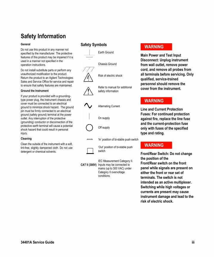
Safety Symbols WARNING
Main Power and Test Input Disconnect: Unplug instrument from wall outlet, remove power cord, and remove all probes from all terminals before servicing. Only qualified, service-trained personnel should remove the cover from the instrument.
WARNING
Line and Current Protection Fuses: For continued protection against fire, replace the line fuse and the current-protection fuse only with fuses of the specified type and rating.
WARNING
Front/Rear Switch: Do not change the position of the Front/Rear switch on the front panel while signals are present on either the front or rear set of terminals. The switch is not intended as an active multiplexer. Switching while high voltages or currents are present may cause instrument damage and lead to the risk of electric shock.
Earth Ground
Chassis Ground
Risk of electric shock
Refer to manual for additional safety information
Alternating Current
On supply
Off supply
‘In’ position of bi-stable push switch
‘Out’ position of bi-stable push switch
CAT II (300V)IEC Measurement Category II. Inputs may be connected to mains (up to 300 VAC) under Category II overvoltage conditions.
iv 34401A Service Guide
WARNING
IEC Measurement Category II. The HI and LO input terminals may be connected to mains in IEC Category II installations for line voltages up to 300 VAC. To avoid the danger of electric shock, do not connect the inputs to mains for line voltages above 300 VAC. See "IEC Measurement Category II Overvoltage Protection" on the following page for further information.
WARNING
Protection Limits: To avoid instrument damage and the risk of electric shock, do not exceed any of the Protection Limits defined in the following section.
Protection Limits
The Agilent 34401A Digital Multimeter provides protection circuitry to prevent damage to the instrument and to protect against the danger of electric shock, provided the Protection Limits are not exceeded. To ensure safe operation of the instrument, do not exceed the Protection Limits shown on the front and rear panel, and defined as follows:
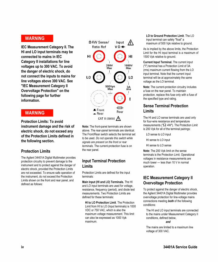
Note: The front-panel terminals are shown above. The rear-panel terminals are identical. The Front/Rear switch selects the terminal set to be used. Do not operate this switch while signals are present on the front or rear terminals. The current-protection fuse is on the rear panel.
Input Terminal Protection Limits
Protection Limits are defined for the input terminals:
Main Input (HI and LO) Terminals. The HI and LO input terminals are used for voltage, resistance, frequency (period), and diode test measurements. Two Protection Limits are defined for these terminals:
HI to LO Protection Limit. The Protection Limit from HI to LO (Input terminals) is 1000 VDC or 750 VAC, which is also the maximum voltage measurement. This limit can also be expressed as 1000 Vpk maximum.
LO to Ground Protection Limit. The LO input terminal can safely "float" a maximum of 500 Vpk relative to ground.
As is implied by the above limits, the Protection Limit for the HI input terminal is a maximum of 1500 Vpk relative to ground.
Current Input Terminal. The current input ("I") terminal has a Protection Limit of 3A (rms) maximum current flowing from the LO input terminal. Note that the current input terminal will be at approximately the same voltage as the LO terminal.
Note: The current-protection circuitry includes a fuse on the rear panel. To maintain protection, replace this fuse only with a fuse of the specified type and rating.
Sense Terminal Protection Limits
The HI and LO sense terminals are used only for four-wire resistance and temperature measurements ("Ω 4W"). The Protection Limit is 200 Vpk for all of the terminal pairings:
LO sense to LO input
HI sense to LO input
HI sense to LO sense
Note: The 200 Vpk limit on the sense terminals is the Protection Limit. Operational voltages in resistance measurements are much lower — less than 10 V in normal operation.
IEC Measurement Category II Overvoltage Protection
To protect against the danger of electric shock, the Agilent 34401A Digital Multimeter provides overvoltage protection for line-voltage mains connections meeting both of the following conditions:
The HI and LO input terminals are connected to the mains under Measurement Category II conditions, defined below,
and
The mains are limited to a maximum line voltage of 300 VAC.
34401A Service Guide v
IEC Measurement Category II includes electrical devices connected to mains at an outlet on a branch circuit. Such devices include most small appliances, test equipment, and other devices that plug into a branch outlet or socket. The 34401A may be used to make measurements with the HI and LO inputs connected to mains in such devices, or to the branch outlet itself (up to 300 VAC). However, the 34401A may not be used with its HI and LO inputs connected to mains in permanently installed electrical devices such as the main circuit-breaker panel, sub-panel disconnect boxes, or permanently wired motors. Such devices and circuits are subject to overvoltages that may exceed the protection limits of the 34401A.
Note: Voltages above 300 VAC may be measured only in circuits that are isolated from mains. However, transient overvoltages are also present on circuits that are isolated from mains. The Agilent 34401A are designed to safely withstand occasional transient overvoltages up to 2500 Vpk. Do not use this equipment to measure circuits where transient overvoltages could exceed this level.
Additional Notices
Waste Electrical and Electronic Equipment (WEEE) Directive 2002/96/EC
This product complies with the WEEE Directive (2002/96/EC) marking requirement. The affixed product label (see below) indicates that you must not discard this electrical/electronic product in domestic household waste.
Product Category: With reference to the equipment types in the WEEE directive Annex 1, this product is classified as a "Monitoring and Control instrumentation" product.
Do not dispose in domestic household waste.
To return unwanted products, contact your local Agilent office, or see www.agilent.com/environment/product for more information.
Agilent 34138A Test Lead Set
The Agilent 34401A is compatible with the Agilent 34138A Test Lead Set described below.
Test Lead Ratings
Test Leads - 1000V, 15A
Fine Tip Probe Attachments - 300V, 3A
Mini Grabber Attachment - 300V, 3A
SMT Grabber Attachments - 300V, 3A
Operation
The Fine Tip, Mini Grabber, and SMT Grabber attachments plug onto the probe end of the Test Leads.
Maintenance
If any portion of the Test Lead Set is worn or damaged, do not use. Replace with a new Agilent 34138A Test Lead Set.
WARNING
If the Test Lead Set is used in a manner not specified by Agilent Technologies, the protection provided by the Test Lead Set may be impaired. Also, do not use a damaged or worn Test Lead Set. Instrument damage or personal injury may result.
DECLARATION OF CONFORMITYAccording to ISO/IEC Guide 22 and CEN/CENELEC EN 45014
Manufacturer’s Name: Agilent Technologies, IncorporatedManufacturer’s Address: 815 – 14th St. SW
Loveland, Colorado 80537USA
Declares, that the product
Product Name: MultimeterModel Number: 34401AProduct Options: This declaration covers all options of the above product(s).
Conforms with the following European Directives:
The product herewith complies with the requirements of the Low Voltage Directive 73/23/EEC and the EMC Directive 89/336/EEC(including 93/68/EEC) and carries the CE Marking accordingly.
Conforms with the following product standards:
EMC Standard
IEC 61326-1:1997+A1:1998 / EN 61326-1:1997+A1:1998 CISPR 11:1990 / EN 55011:1991 IEC 61000-4-2:1995+A1:1998 / EN 61000-4-2:1995 IEC 61000-4-3:1995 / EN 61000-4-3:1995 IEC 61000-4-4:1995 / EN 61000-4-4:1995 IEC 61000-4-5:1995 / EN 61000-4-5:1995 IEC 61000-4-6:1996 / EN 61000-4-6:1996 IEC 61000-4-11:1994 / EN 61000-4-11:1994
Canada: ICES-001:1998 Australia/New Zealand: AS/NZS 2064.1
Limit
Group 1 Class A4kV CD, 8kV AD3 V/m, 80-1000 MHz0.5kV signal lines, 1kV power lines0.5 kV line-line, 1 kV line-ground3V, 0.15-80 MHzDips: 30% 10ms; 60% 100msInterrupt > 95%@5000ms
The product was tested in a typical configuration with Agilent Technologies test systems.
Safety IEC 61010-1:1990+A1:1992+A2:1995 / EN 61010-1:1993+A2:1995Canada: CSA C22.2 No. 1010.1:1992UL 3111-1: 1994
18 July 2001Date Ray Corson
Product Regulations Program Manager
For further information, please contact your local Agilent Technologies sales office, agent or distr butor.Authorized EU-representative: Agilent Technologies Deutschland GmbH, Herrenberger Straβe 130, D 71034 Böblingen, Germany
Note: Unless otherwise indicated, this manual applies to all serial numbers.
The Agilent Technologies 34401A is a 61⁄2-digit, high-performancedigital multimeter. Its combination of bench-top and system featuresmakes this multimeter a versatile solution for your measurement needsnow and in the future.
Convenient Bench-Top Features
• Highly visible vacuum-fluorescent display
• Built-in math operations
• Continuity and diode test functions
• Hands-free, Reading Hold feature
• Portable, ruggedized case with non-skid feet
Flexible System Features
• GPIB (IEEE-488) interface and RS-232 interface
• Standard programming languages: SCPI, Agilent 3478A, andFluke 8840
• Reading rates up to 1000 readings per second
• Storage for up to 512 readings
• Limit testing with pass/fail signals
• Optional 34812A IntuiLink/Meter Softwarefor Microsoft® WindowsTM
WarningThe procedures in this manual are intended for use by qualified,service-trained personnel only.
Agilent 34401A Multimeter
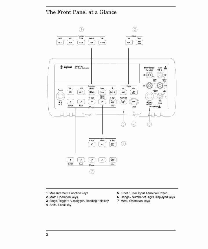
The Front Panel at a Glance
1 Measurement Function keys 2 Math Operation keys 3 Single Trigger / Autotrigger / Reading Hold key4 Shift / Local key
5 Front / Rear Input Terminal Switch 6 Range / Number of Digits Displayed keys7 Menu Operation keys
2

The Front-Panel Menu at a Glance
A: MEASurement MENU
1: AC FILTER > 2: CONTINUITY > 3: INPUT R > 4: RATIO FUNC > 5: RESOLUTION
F: CALibration MENU*
1: SECURED > [ 1: UNSECURED ] > [ 2: CALIBRATE ] > 3: CAL COUNT > 4: MESSAGE
* The commands enclosed in square brackets ( [ ] ) are “hidden” unless the multimeteris UNSECURED for calibration.
B: MATH MENU
1: MIN-MAX > 2: NULL VALUE > 3: dB REL > 4: dBm REF R > 5: LIMIT TEST > 6: HIGH LIMIT > 7: LOW LIMIT
C: TRIGger MENU
1: READ HOLD > 2: TRIG DELAY > 3: N SAMPLES
D: SYStem MENU
1: RDGS STORE > 2: SAVED RDGS > 3: ERROR > 4: TEST > 5: DISPLAY > 6 : BEEP > 7: COMMA > 8 : REVISION
E: Input / Output MENU
1: HP-IB ADDR > 2: INTERFACE > 3: BAUD RATE > 4: PARITY > 5: LANGUAGE
The menu is organized in a top-down tree structure with three levels.
3
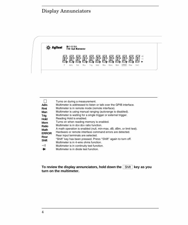
Display Annunciators
Adrs Rmt Man Trig Hold Mem Ratio Math ERRORRear Shift
Turns on during a measurement. Multimeter is addressed to listen or talk over the GPIB interface. Multimeter is in remote mode (remote interface). Multimeter is using manual ranging (autorange is disabled). Multimeter is waiting for a single trigger or external trigger. Reading Hold is enabled. Turns on when reading memory is enabled. Multimeter is in dcv:dcv ratio function. A math operation is enabled (null, min-max, dB, dBm, or limit test). Hardware or remote interface command errors are detected. Rear input terminals are selected. “Shift” key has been pressed. Press “Shift” again to turn off.Multimeter is in 4-wire ohms function. Multimeter is in continuity test function. Multimeter is in diode test function.
To review the display annunciators, hold down the Shift key as youturn on the multimeter.
∗
4
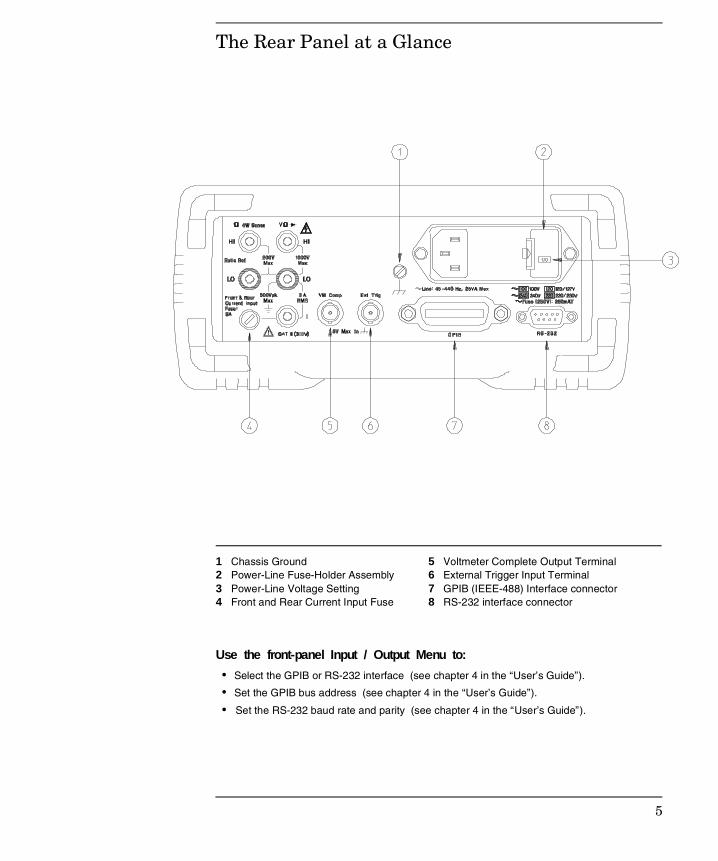
The Rear Panel at a Glance
1 Chassis Ground 2 Power-Line Fuse-Holder Assembly 3 Power-Line Voltage Setting 4 Front and Rear Current Input Fuse
5 Voltmeter Complete Output Terminal 6 External Trigger Input Terminal 7 GPIB (IEEE-488) Interface connector 8 RS-232 interface connector
Use the front-panel Input / Output Menu to:
• Select the GPIB or RS-232 interface (see chapter 4 in the “User’s Guide”).
• Set the GPIB bus address (see chapter 4 in the “User’s Guide”).
• Set the RS-232 baud rate and parity (see chapter 4 in the “User’s Guide”).
5
In This Book
Specifications Chapter 1 lists the multimeter’s specifications anddescribes how to interpret these specifications.
Quick Start Chapter 2 prepares the multimeter for use and helps youget familiar with a few of its front-panel features.
Menu Tutorial Chapter 3 introduces you to the front-panel menu andsteps you through several simple menu examples.
Calibration Procedures Chapter 4 provides a detailed description ofthe multimeter’s calibrations and adjustments.
Theory of Operation Chapter 5 describes each functional block in themultimeter.
Service Chapter 6 provides guidelines for returning your multimeterto Agilent for servicing, or for servicing it yourself.
Replaceable Parts Chapter 7 contains a detailed parts list of themultimeter.
Backdating Chapter 8 describes the procedures involved with backissues of this manual.
Schematics Chapter 9 provides the multimeter’s schematics.
If you have questions relating to the operation of the Agilent 34401A,call 1-800-452-4844 in the United States, or contact your nearest Agilent Sales Office.
If your 34401A fails within one year of purchase, Agilent will repair orreplace it free of charge. Call 1-877-444-7278 (“Agilent Express”) in theUnited States, or contact your nearest Agilent Sales Office.
6
Contents
Chapter 1 Specifications
DC Characteristics 12AC Characteristics 14Frequency and Period Characteristics 16General Information 18Product Dimensions 19To Calculate Total Measurement Error 20Interpreting Multimeter Specifications 22Configuring for Highest Accuracy Measurements 25
Chapter 2 Quick Start
To Prepare the Multimeter for Use 29If the Multimeter Does Not Turn On 30To Adjust the Carrying Handle 32To Measure Voltage 33To Measure Resistance 33To Measure Current 34To Measure Frequency (or Period) 34To Test Continuity 35To Check Diodes 35To Select a Range 36To Set the Resolution 37To Make Null (Relative) Measurements 38To Store Minimum and Maximum Readings 39To Make dB Measurements 40To Make dBm Measurements 41To Trigger the Multimeter 42To Make dcv:dcv Ratio Measurements 43Front-Panel Display Formats 44To Rack Mount the Multimeter 45
Chapter 3 Menu Tutorial
Front-Panel Menu Reference 49A Front-Panel Menu Tutorial 51Menu Examples 53
Co
nten
ts
7
Chapter 4 Calibration Procedures
Agilent Calibration Services 61Calibration Interval 61Time Required for Calibration 61Automating Calibration Procedures 62Recommended Test Equipment 63Test Considerations 64Performance Verification Tests 65Zero Offset Verification 67Gain Verification 69Optional AC Performance Verification Tests 72Calibration Security Code 73Calibration Count 75Calibration Message 75Calibration Procedures 76Aborting a Calibration in Progress 76Zero Adjustment 77Gain Adjustment 79Optional Gain Calibration Procedures 82Understanding the AC Signal Filter 85Understanding Resolution 86Error Messages 89
Chapter 5 Theory of Operation
Block Diagram 93Front/Rear Selection 94Function Switching 95DC Amplifier 96Ohms Current Source 98AC Circuit 99A-to-D Converter 101Floating Logic 103Earth-Referenced Logic 105Power Supplies 106Front Panel 107
Co
nte
nts
Contents
8
Chapter 6 Service
Operating Checklist 111Types of Service Available 112Repackaging for Shipment 113Electrostatic Discharge (ESD) Precautions 114Surface Mount Repair 114To Replace the Power-Line Fuse 114To Replace The Current Input Fuses 115To Connect Pass/Fail Output Signals 115Troubleshooting Hints 117Self-Test Procedures 120
Chapter 7 Replaceable Parts
To Order Replaceable Parts 126Backdating and Part Changes 126 Replaceable Parts: 34401-66501 (Main Assembly) 127Replaceable Parts: 34401-66512 (Display Assembly) 133Replaceable Parts: Agilent 34401A Mainframe 134 Manufacturer’s List 135
Chapter 8 Backdating 137
Chapter 9 Schematics
Mechanical Disassembly 9-3Component Locator Diagram – Main Board (34401-66501) 9-5Component Locator Diagram – Front Panel (34401-66512) 9-6Agilent 34401A Block Diagram 9-7Front/Rear Selection Schematic 9-8Function Switching Schematic 9-9DC Amplifier and Ohms Schematic 9-10AC Circuit Schematic 9-11A/D Converter Schematic 9-12Floating Logic Schematic 9-13Earth-Referenced Logic Schematic 9-14Power Supplies Schematic 9-15Front-Panel Display Schematic 9-16
Co
nten
tsContents
9

Co
nte
nts
10

1
Specifications
1
DC Characteristics
DC Characteristics
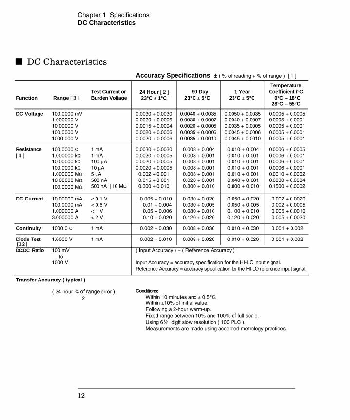
Accuracy Specifications ± ( % of reading + % of range ) [ 1 ]
Function
Range [ 3 ]Test Current or Burden Voltage
90 Day 23°C ± 5°C
1 Year 23°C ± 5°C
Temperature Coefficient /°C 0°C – 18°C 28°C – 55°C
DC Voltage 100.0000 mV
1.000000 V 10.00000 V 100.0000 V 1000.000 V
0.0030 + 0.00300.0020 + 0.00060.0015 + 0.00040.0020 + 0.00060.0020 + 0.0006
0.0040 + 0.00350.0030 + 0.00070.0020 + 0.00050.0035 + 0.00060.0035 + 0.0010
0.0050 + 0.00350.0040 + 0.00070.0035 + 0.00050.0045 + 0.00060.0045 + 0.0010
0.0005 + 0.00050.0005 + 0.00010.0005 + 0.00010.0005 + 0.00010.0005 + 0.0001
Resistance [ 4 ]
100.0000 Ω1.000000 kΩ10.00000 kΩ100.0000 kΩ1.000000 MΩ10.00000 MΩ100.0000 MΩ
1 mA1 mA100 µA10 µA5 µA500 nA500 nA || 10 MΩ
0.0030 + 0.00300.0020 + 0.00050.0020 + 0.00050.0020 + 0.0005 0.002 + 0.001 0.015 + 0.001 0.300 + 0.010
0.008 + 0.004 0.008 + 0.001 0.008 + 0.001 0.008 + 0.001 0.008 + 0.001 0.020 + 0.001 0.800 + 0.010
0.010 + 0.004 0.010 + 0.001 0.010 + 0.001 0.010 + 0.001 0.010 + 0.001 0.040 + 0.001 0.800 + 0.010
0.0006 + 0.00050.0006 + 0.00010.0006 + 0.00010.0006 + 0.00010.0010 + 0.00020.0030 + 0.00040.1500 + 0.0002
DC Current 10.00000 mA100.0000 mA1.000000 A3.000000 A
< 0.1 V< 0.6 V< 1 V< 2 V
0.005 + 0.010 0.01 + 0.004 0.05 + 0.006 0.10 + 0.020
0.030 + 0.020 0.030 + 0.005 0.080 + 0.010 0.120 + 0.020
0.050 + 0.020 0.050 + 0.005 0.100 + 0.010 0.120 + 0.020
0.002 + 0.0020 0.002 + 0.0005 0.005 + 0.0010 0.005 + 0.0020
Continuity 1000.0 Ω 1 mA 0.002 + 0.030 0.008 + 0.030 0.010 + 0.030 0.001 + 0.002
Diode Test[12]
1.0000 V 1 mA 0.002 + 0.010 0.008 + 0.020 0.010 + 0.020 0.001 + 0.002
DC:DC Ratio 100 mV to1000 V
( Input Accuracy ) + ( Reference Accuracy )
Input Accuracy = accuracy specification for the HI-LO input signal. Reference Accuracy = accuracy specification for the HI-LO reference input signal.
Transfer Accuracy ( typical )
( 24 hour % of range error )2
Conditions: Within 10 minutes and ± 0.5°C. Within ±10% of initial value. Following a 2-hour warm-up. Fixed range between 10% and 100% of full scale. Using 61⁄2 digit slow resolution ( 100 PLC ). Measurements are made using accepted metrology practices.
24 Hour [ 2 ] 23°C ± 1°C
Chapter 1 Specifications
12
DC Characteristics
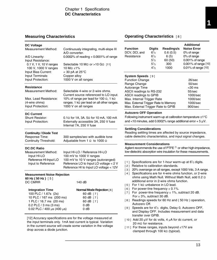
Function DCV, DCI, andResistance
Digits 61⁄2 61⁄2 51⁄2 51⁄2 41⁄2
Readings/s 0.6 (0.5) 6 (5) 60 (50) 300 1000
Additional Noise Error 0% of range0% of range0.001% of range 0.001% of range0.01% of range
System Speeds [ 9 ]Function ChangeRange ChangeAutorange Time ASCII readings to RS-232ASCII readings to GPIBMax. Internal Trigger RateMax. External Trigger Rate to MemoryMax. External Trigger Rate to GPIB
26/sec 50/sec <30 ms 55/sec 1000/sec 1000/sec 1000/sec 900/sec
Operating Characteristics [ 8 ]
[10][10]
Measurement Noise Rejection 60 Hz ( 50 Hz ) [ 5 ]DC CMRR
Integration Time 100 PLC / 1.67s (2s) 10 PLC / 167 ms (200 ms) 1 PLC / 16.7 ms (20 ms) 0.2 PLC / 3 ms (3 ms) 0.02 PLC / 400 µs (400 µs)
140 dB
Normal Mode Rejection [ 6 ] 60 dB [ 7 ] 60 dB [ 7 ] 60 dB [ 7 ] 0 dB 0 dB
[12] Accuracy specifications are for the voltage measured atthe input terminals only. 1mA test current is typical. Variationin the current source will create some variation in the voltagedrop across a diode junction.
DC VoltageMeasurement Method:
A/D Linearity: Input Resistance: 0.1 V, 1 V, 10 V ranges 100 V, 1000 V rangesInput Bias Current: Input Terminals: Input Protection:
ResistanceMeasurement Method:
Max. Lead Resistance: (4-wire ohms) Input Protection:
DC Current Shunt Resistor:Input Protection:
Continuity / Diode Test Response Time: Continuity Threshold:
DC:DC Ratio Measurement Method: Input HI-LO Reference HI-Input LO Input to Reference
Continuously integrating, multi-slope III A/D converter. 0.0002% of reading + 0.0001% of range
Selectable 10 MΩ or >10 GΩ [11]10 MΩ ±1%< 30 pA at 25°CCopper alloy1000 V on all ranges
Selectable 4-wire or 2-wire ohms. Current source referenced to LO input.10% of range per lead for 100 Ω, 1 kΩ ranges. 1 kΩ per lead on all other ranges.1000 V on all ranges
0.1Ω for 1A, 3A. 5Ω for 10 mA, 100 mAExternally accessible 3A, 250 V fuseInternal 7A, 250 V fuse
300 samples/sec with audible toneAdjustable from 1 Ω to 1000 Ω
Input HI-LO / Reference HI-LO100 mV to 1000 V ranges 100 mV to 10 V ranges (autoranged) Reference LO to Input LO voltage < 2 V Reference HI to Input LO voltage < 12V
Measuring Characteristics
Autozero OFF Operation Following instrument warm-up at calibration temperature ±1°C and <10 minutes, add 0.0002% range additional error + 5 µV.
Settling Considerations Reading settling times are affected by source impedance, cable dielectric characteristics, and input signal changes.
Measurement Considerations Agilent recommends the use of PTFE or other high-impedance, low-dielectric absorption wire insulation for these measurements.
[ 1 ] Specifications are for 1-hour warm-up at 61⁄2 digits.[ 2 ] Relative to calibration standards.[ 3 ] 20% overrange on all ranges, except 1000 Vdc, 3 A range.[ 4 ] Specifications are for 4-wire ohms function, or 2-wire ohms using Math Null. Without Math Null, add 0.2 Ω additional error in 2-wire ohms function.[ 5 ] For 1 kΩ unbalance in LO lead.[ 6 ] For power-line frequency ± 0.1%.[ 7 ] For power-line frequency ± 1%, subtract 20 dB. For ± 3%, subtract 30 dB.[ 8 ] Readings speeds for 60 Hz and ( 50 Hz ) operation, Autozero Off.[ 9 ] Speeds are for 41⁄2 digits, Delay 0, Autozero OFF, and Display OFF. Includes measurement and data transfer over GPIB.[ 10 ] Add 20 µV for dc volts, 4 µA for dc current, or 20 mΩ for resistance. [ 11 ] For these ranges, inputs beyond ±17V are clamped through 100 kΩ (typical).
1
Chapter 1 Specifications
13

AC Characteristics
AC Characteristics
Accuracy Specifications ± ( % of reading + % of range ) [ 1 ]
Function Range [ 3 ] Frequency24 Hour [ 2 ]23°C ± 1°C
1 Year 23°C ± 5°C
Temperature Coefficient/°C 0°C – 18°C28°C – 55°C
True RMS AC Voltage[ 4 ]
100.0000 mV
1.000000 V to750.000 V
3 Hz – 5 Hz5 Hz – 10 Hz10 Hz – 20 kHz20 kHz – 50 kHz50 kHz – 100 kHz100 kHz – 300 kHz [6]
3 Hz – 5 Hz5 Hz – 10 Hz10 Hz – 20 kHz20 kHz – 50 kHz50 kHz – 100 kHz [5]100 kHz – 300 kHz [6]
1.00 + 0.030.35 + 0.030.04 + 0.030.10 + 0.050.55 + 0.084.00 + 0.50
1.00 + 0.020.35 + 0.020.04 + 0.020.10 + 0.040.55 + 0.084.00 + 0.50
1.00 + 0.040.35 + 0.040.05 + 0.040.11 + 0.050.60 + 0.084.00 + 0.50
1.00 + 0.030.35 + 0.030.05 + 0.030.11 + 0.050.60 + 0.084.00 + 0.50
1.00 + 0.040.35 + 0.040.06 + 0.040.12 + 0.050.60 + 0.084.00 + 0.50
1.00 + 0.030.35 + 0.030.06 + 0.030.12 + 0.050.60 + 0.084.00 + 0.50
0.100 + 0.0040.035 + 0.0040.005 + 0.0040.011 + 0.0050.060 + 0.008 0.20 + 0.02
0.100 + 0.0030.035 + 0.0030.005 + 0.0030.011 + 0.0050.060 + 0.008 0.20 + 0.02
True RMS AC Current[ 4 ]
1.000000 A
3.00000 A
3 Hz – 5 Hz5 Hz – 10 Hz10 Hz – 5 kHz
3 Hz – 5 Hz5 Hz – 10 Hz10 Hz – 5 kHz
1.00 + 0.040.30 + 0.040.10 + 0.04
1.10 + 0.060.35 + 0.060.15 + 0.06
1.00 + 0.040.30 + 0.040.10 + 0.04
1.10 + 0.060.35 + 0.060.15 + 0.06
1.00 + 0.040.30 + 0.040.10 + 0.04
1.10 + 0.060.35 + 0.060.15 + 0.06
0.100 + 0.0060.035 + 0.0060.015 + 0.006
0.100 + 0.0060.035 + 0.0060.015 + 0.006
Additional Low Frequency Errors ( % of reading )
Frequency AC Filter Slow Medium Fast 0 0.74 –– 0 0.22 –– 0 0.06 0.73 0 0.01 0.22 0 0 0.18 0 0 0
10 Hz – 20 Hz20 Hz – 40 Hz40 Hz – 100 Hz100 Hz – 200 Hz200 Hz – 1 kHz> 1 kHz
Sinewave Transfer Accuracy ( typical )
Frequency10 Hz – 50 kHz50 kHz – 300 kHz
Error ( % of range ) 0.002% 0.005%
Conditions: Sinewave input. Within 10 minutes and ± 0.5°C. Within ±10% of initial voltage and ±1% of initial frequency. Following a 2-hour warm-up. Fixed range between 10% and 100% of full scale ( and <120 V ). Using 61⁄2 digit resolution. Measurements are made using accepted metrology practices.
90 Day 23°C ± 5°C
Additional Crest Factor Errors ( non-sinewave ) [ 7 ]
Crest Factor 1 – 2 2 – 3 3 – 4 4 – 5
Error ( % of reading ) 0.05% 0.15% 0.30% 0.40%
Chapter 1 Specifications
14
AC Characteristics
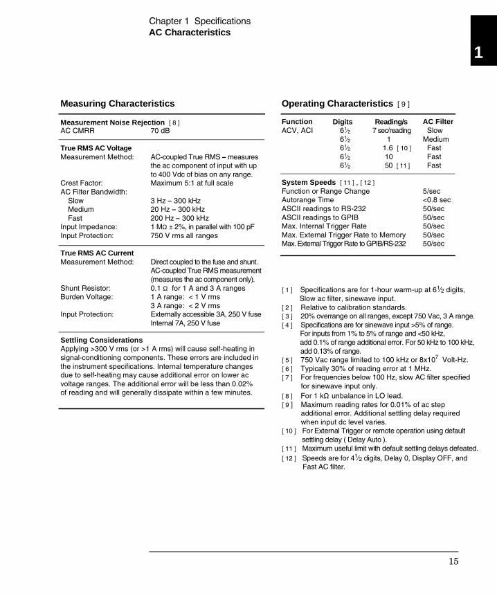
Measurement Noise Rejection [ 8 ] AC CMRR
True RMS AC Voltage Measurement Method:
Crest Factor:AC Filter Bandwidth: Slow Medium FastInput Impedance: Input Protection:
True RMS AC Current Measurement Method:
Shunt Resistor: Burden Voltage:
Input Protection:
70 dB
AC-coupled True RMS – measuresthe ac component of input with upto 400 Vdc of bias on any range.Maximum 5:1 at full scale
3 Hz – 300 kHz20 Hz – 300 kHz200 Hz – 300 kHz1 MΩ ± 2%, in parallel with 100 pF750 V rms all ranges
Direct coupled to the fuse and shunt.AC-coupled True RMS measurement(measures the ac component only).0.1 Ω for 1 A and 3 A ranges1 A range: < 1 V rms3 A range: < 2 V rmsExternally accessible 3A, 250 V fuseInternal 7A, 250 V fuse
Settling Considerations Applying >300 V rms (or >1 A rms) will cause self-heating insignal-conditioning components. These errors are included inthe instrument specifications. Internal temperature changesdue to self-heating may cause additional error on lower acvoltage ranges. The additional error will be less than 0.02%of reading and will generally dissipate within a few minutes.
Measuring Characteristics
Function ACV, ACI 61⁄2
61⁄2 61⁄2 61⁄2 61⁄2
7 sec/reading 1 1.6 [ 10 ] 10 50 [ 11 ]
AC Filter SlowMedium Fast Fast Fast
System Speeds [ 11 ] , [ 12 ]Function or Range ChangeAutorange TimeASCII readings to RS-232ASCII readings to GPIBMax. Internal Trigger RateMax. External Trigger Rate to MemoryMax. External Trigger Rate to GPIB/RS-232
5/sec<0.8 sec50/sec50/sec50/sec50/sec50/sec
Operating Characteristics [ 9 ]
Reading/sDigits
[ 1 ] Specifications are for 1-hour warm-up at 61⁄2 digits, Slow ac filter, sinewave input. [ 2 ] Relative to calibration standards.[ 3 ] 20% overrange on all ranges, except 750 Vac, 3 A range.[ 4 ] Specifications are for sinewave input >5% of range. For inputs from 1% to 5% of range and <50 kHz, add 0.1% of range additional error. For 50 kHz to 100 kHz, add 0.13% of range.[ 5 ] 750 Vac range limited to 100 kHz or 8x10⁷ Volt-Hz.[ 6 ] Typically 30% of reading error at 1 MHz.[ 7 ] For frequencies below 100 Hz, slow AC filter specified for sinewave input only. [ 8 ] For 1 kΩ unbalance in LO lead.[ 9 ] Maximum reading rates for 0.01% of ac step additional error. Additional settling delay required when input dc level varies.[ 10 ] For External Trigger or remote operation using default settling delay ( Delay Auto ).[ 11 ] Maximum useful limit with default settling delays defeated.[ 12 ] Speeds are for 41⁄2 digits, Delay 0, Display OFF, and Fast AC filter.
1
Chapter 1 Specifications
15
Frequency and Period Characteristics
Frequency and Period Characteristics
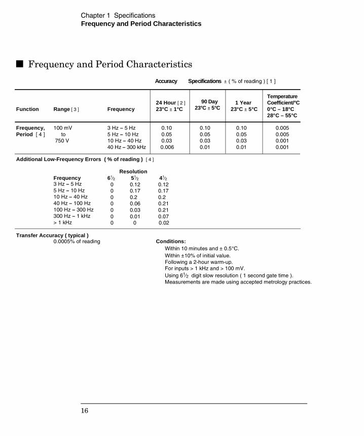
Accuracy Specifications ± ( % of reading ) [ 1 ]
Function Range [ 3 ] Frequency24 Hour [ 2 ]23°C ± 1°C
1 Year23°C ± 5°C
Temperature Coefficient/°C0°C – 18°C28°C – 55°C
Frequency,Period [ 4 ]
100 mV to 750 V
3 Hz – 5 Hz5 Hz – 10 Hz10 Hz – 40 Hz40 Hz – 300 kHz
0.10 0.05 0.03 0.006
0.10 0.05 0.03 0.01
0.10 0.05 0.03 0.01
0.005 0.005 0.001 0.001
Additional Low-Frequency Errors ( % of reading ) [ 4 ]
Frequency Resolution61⁄2 51⁄2 41⁄2 0 0.12 0.12 0 0.17 0.17 0 0.2 0.2 0 0.06 0.21 0 0.03 0.21 0 0.01 0.07 0 0 0.02
3 Hz – 5 Hz5 Hz – 10 Hz10 Hz – 40 Hz40 Hz – 100 Hz100 Hz – 300 Hz300 Hz – 1 kHz> 1 kHz
Transfer Accuracy ( typical ) 0.0005% of reading Conditions:
Within 10 minutes and ± 0.5°C. Within ±10% of initial value. Following a 2-hour warm-up. For inputs > 1 kHz and > 100 mV. Using 61⁄2 digit slow resolution ( 1 second gate time ). Measurements are made using accepted metrology practices.
90 Day 23°C ± 5°C
Chapter 1 Specifications
16
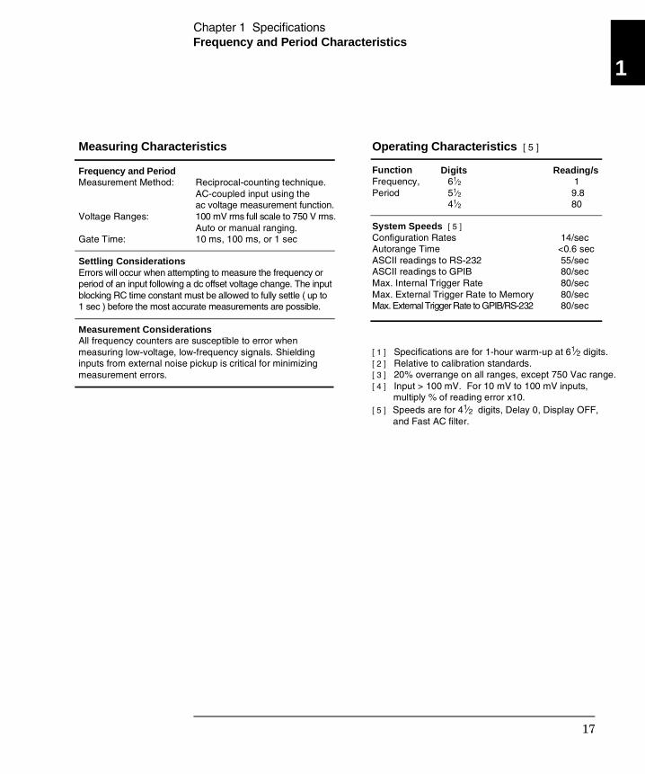
Frequency and Period Characteristics
Frequency and Period Measurement Method:
Voltage Ranges:
Gate Time:
Reciprocal-counting technique.AC-coupled input using the ac voltage measurement function.100 mV rms full scale to 750 V rms.Auto or manual ranging.10 ms, 100 ms, or 1 sec
Settling Considerations Errors will occur when attempting to measure the frequency orperiod of an input following a dc offset voltage change. The inputblocking RC time constant must be allowed to fully settle ( up to1 sec ) before the most accurate measurements are possible.
Measurement Considerations All frequency counters are susceptible to error whenmeasuring low-voltage, low-frequency signals. Shieldinginputs from external noise pickup is critical for minimizingmeasurement errors.
Measuring Characteristics
Function Frequency,Period
61⁄2 51⁄2 41⁄2
1 9.8 80
System Speeds [ 5 ]Configuration RatesAutorange TimeASCII readings to RS-232ASCII readings to GPIBMax. Internal Trigger RateMax. External Trigger Rate to MemoryMax. External Trigger Rate to GPIB/RS-232
14/sec <0.6 sec 55/sec 80/sec 80/sec 80/sec 80/sec
[ 1 ] Specifications are for 1-hour warm-up at 61⁄2 digits.[ 2 ] Relative to calibration standards.[ 3 ] 20% overrange on all ranges, except 750 Vac range.[ 4 ] Input > 100 mV. For 10 mV to 100 mV inputs, multiply % of reading error x10.[ 5 ] Speeds are for 41⁄2 digits, Delay 0, Display OFF, and Fast AC filter.
Operating Characteristics [ 5 ]
Digits Reading/s
1
Chapter 1 Specifications
17
General Information
General Information
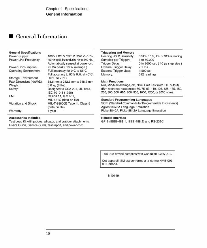
General Specifications Power Supply: Power Line Frequency:
Power Consumption:Operating Environment:
Storage Environment:Rack Dimensions (HxWxD):Weight:Safety:
EMI:
Vibration and Shock:
Warranty:
100 V / 120 V / 220 V / 240 V ±10%.45 Hz to 66 Hz and 360 Hz to 440 Hz.Automatically sensed at power-on.25 VA peak ( 10 W average )Full accuracy for 0°C to 55°CFull accuracy to 80% R.H. at 40°C-40°C to 70°C88.5 mm x 212.6 mm x 348.3 mm3.6 kg (8 lbs) Designed to CSA 231, UL 1244, IEC 1010-1 (1990) CISPR 11, IEC 801, MIL-461C (data on file)MIL-T-28800E Type III, Class 5(data on file)1 year
Accessories Included Test Lead Kit with probes, alligator, and grabber attachments. User’s Guide, Service Guide, test report, and power cord.
Triggering and MemoryReading HOLD Sensitivity:Samples per Trigger:Trigger Delay:External Trigger Delay:External Trigger Jitter:Memory:
0.01%, 0.1%, 1%, or 10% of reading1 to 50,0000 to 3600 sec ( 10 µs step size )< 1 ms< 500 µs 512 readings
Math Functions Null, Min/Max/Average, dB, dBm, Limit Test (with TTL output).dBm reference resistances: 50, 75, 93, 110, 124, 125, 135, 150, 250, 300, 500, 600, 800, 900, 1000, 1200, or 8000 ohms.
Standard Programming Languages SCPI (Standard Commands for Programmable Instruments) Agilent 3478A Language Emulation Fluke 8840A, Fluke 8842A Language Emulation
Remote Interface GPIB (IEEE-488.1, IEEE-488.2) and RS-232C
N10149
This ISM device complies with Canadian ICES-001.
Cet appareil ISM est conforme à la norme NMB-001du Canada.
Chapter 1 Specifications
18
Product Dimensions
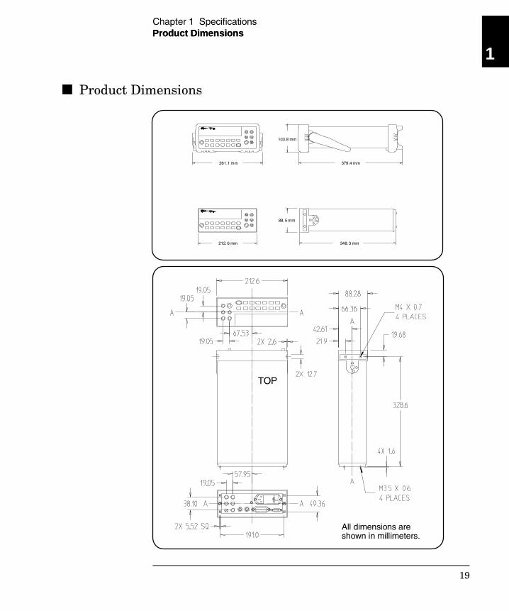
Product Dimensions
348. 3 mm
88. 5 mm
212. 6 mm
261.1 mm 379.4 mm
103.8 mm
TOP
Product Dimensions
All dimensions areshown in millimeters.
1
Chapter 1 Specifications
19
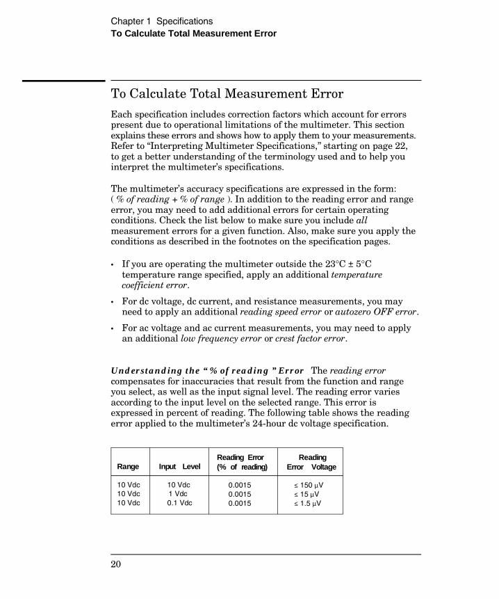
To Calculate Total Measurement Error
Each specification includes correction factors which account for errorspresent due to operational limitations of the multimeter. This sectionexplains these errors and shows how to apply them to your measurements.Refer to “Interpreting Multimeter Specifications,” starting on page 22,to get a better understanding of the terminology used and to help youinterpret the multimeter’s specifications.
The multimeter’s accuracy specifications are expressed in the form: ( % of reading + % of range ). In addition to the reading error and rangeerror, you may need to add additional errors for certain operatingconditions. Check the list below to make sure you include allmeasurement errors for a given function. Also, make sure you apply theconditions as described in the footnotes on the specification pages.
• If you are operating the multimeter outside the 23°C ± 5°Ctemperature range specified, apply an additional temperaturecoefficient error.
• For dc voltage, dc current, and resistance measurements, you mayneed to apply an additional reading speed error or autozero OFF error.
• For ac voltage and ac current measurements, you may need to applyan additional low frequency error or crest factor error.
Understanding the “ % of reading ” Error The reading errorcompensates for inaccuracies that result from the function and rangeyou select, as well as the input signal level. The reading error variesaccording to the input level on the selected range. This error isexpressed in percent of reading. The following table shows the readingerror applied to the multimeter’s 24-hour dc voltage specification.
Range
10 Vdc10 Vdc10 Vdc
Input Level
10 Vdc 1 Vdc 0.1 Vdc
Reading Error (% of reading)
0.0015 0.0015 0.0015
ReadingError Voltage
≤ 150 µV ≤ 15 µV ≤ 1.5 µV
Chapter 1 SpecificationsTo Calculate Total Measurement Error
20
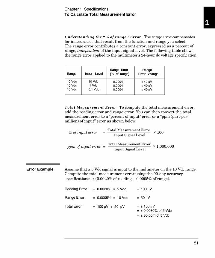
Understanding the “ % of range ” Error The range error compensatesfor inaccuracies that result from the function and range you select.The range error contributes a constant error, expressed as a percent ofrange, independent of the input signal level. The following table showsthe range error applied to the multimeter’s 24-hour dc voltage specification.
Total Measurement Error To compute the total measurement error,add the reading error and range error. You can then convert the totalmeasurement error to a “percent of input” error or a “ppm (part-per-million) of input” error as shown below.
% of input error = Total Measurement Error Input Signal Level
× 100
ppm of input error = Total Measurement Error Input Signal Level
× 1,000,000
Error Example Assume that a 5 Vdc signal is input to the multimeter on the 10 Vdc range.Compute the total measurement error using the 90-day accuracyspecifications: ± (0.0020% of reading + 0.0005% of range).
Range
10 Vdc10 Vdc10 Vdc
Input Level
10 Vdc 1 Vdc 0.1 Vdc
Range Error (% of range)
0.0004 0.0004 0.0004
RangeError Voltage
≤ 40 µV ≤ 40 µV ≤ 40 µV
Reading Error
Range Error
Total Error
= 0.0020% × 5 Vdc
= 0.0005% × 10 Vdc
= 100 µV + 50 µV
= 100 µV
= 50 µV
= ± 150 µV = ± 0.0030% of 5 Vdc = ± 30 ppm of 5 Vdc
1
Chapter 1 SpecificationsTo Calculate Total Measurement Error
21
Interpreting Multimeter Specifications
This section is provided to give you a better understanding of the terminologyused and will help you interpret the multimeter’s specifications.
Number of Digits and Overrange
The “number of digits” specification is the most fundamental, andsometimes, the most confusing characteristic of a multimeter.The number of digits is equal to the maximum number of “9’s” themultimeter can measure or display. This indicates the number of fulldigits. Most multimeters have the ability to overrange and add a partialor “1⁄2” digit.
For example, the Agilent 34401A can measure 9.99999 Vdc on the 10 Vrange. This represents six full digits of resolution. The multimeter canalso overrange on the 10 V range and measure up to a maximum of12.00000 Vdc. This corresponds to a 61⁄2-digit measurement with 20%overrange capability.
Sensitivity
Sensitivity is the minimum level that the multimeter can detect for agiven measurement. Sensitivity defines the ability of the multimeter torespond to small changes in the input level. For example, suppose youare monitoring a 1 mVdc signal and you want to adjust the level towithin ±1 µV. To be able to respond to an adjustment this small, thismeasurement would require a multimeter with a sensitivity of at least 1 µV.You could use a 61⁄2-digit multimeter if it has a 1 Vdc or smaller range.You could also use a 41⁄2-digit multimeter with a 10 mVdc range.
For ac voltage and ac current measurements, note that the smallestvalue that can be measured is different from the sensitivity. For theAgilent 34401A, these functions are specified to measure down to 1% ofthe selected range. For example, the multimeter can measure down to1 mV on the 100 mV range.
Chapter 1 SpecificationsInterpreting Multimeter Specifications
22
Resolution Resolution is the numeric ratio of the maximum displayed value dividedby the minimum displayed value on a selected range. Resolution isoften expressed in percent, parts-per-million (ppm), counts, or bits.For example, a 61⁄2-digit multimeter with 20% overrange capability candisplay a measurement with up to 1,200,000 counts of resolution.This corresponds to about 0.0001% (1 ppm) of full scale, or 21 bitsincluding the sign bit. All four specifications are equivalent.
Accuracy
Accuracy is a measure of the “exactness” to which the multimeter’smeasurement uncertainty can be determined relative to the calibrationreference used. Absolute accuracy includes the multimeter’s relativeaccuracy specification plus the known error of the calibration referencerelative to national standards (such as the U.S. National Institute ofStandards and Technology). To be meaningful, the accuracy specificationsmust be accompanied with the conditions under which they are valid.These conditions should include temperature, humidity, and time.
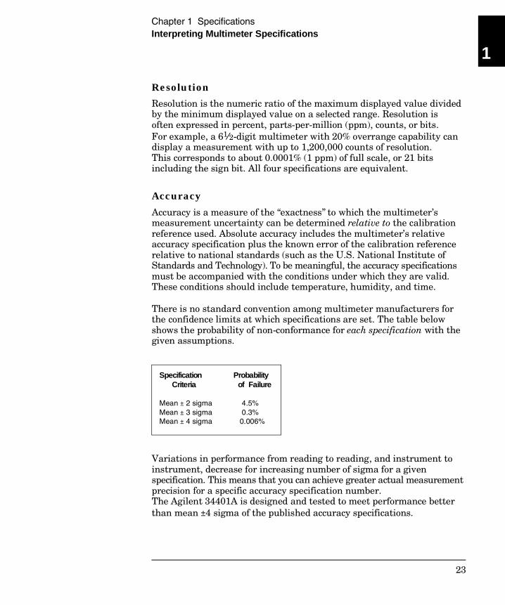
There is no standard convention among multimeter manufacturers forthe confidence limits at which specifications are set. The table belowshows the probability of non-conformance for each specification with thegiven assumptions.
Variations in performance from reading to reading, and instrument toinstrument, decrease for increasing number of sigma for a givenspecification. This means that you can achieve greater actual measurementprecision for a specific accuracy specification number.The Agilent 34401A is designed and tested to meet performance betterthan mean ±4 sigma of the published accuracy specifications.
Specification Criteria
Mean ± 2 sigma Mean ± 3 sigma Mean ± 4 sigma
Probability of Failure
4.5% 0.3% 0.006%
1
Chapter 1 SpecificationsInterpreting Multimeter Specifications
23
Transfer Accuracy Transfer accuracy refers to the error introduced by the multimeterdue to noise and short-term drift. This error becomes apparent whencomparing two nearly-equal signals for the purpose of “transferring”the known accuracy of one device to the other.
24-Hour Accuracy
The 24-hour accuracy specification indicates the multimeter’s relativeaccuracy over its full measurement range for short time intervals andwithin a stable environment. Short-term accuracy is usually specifiedfor a 24-hour period and for a ±1°C temperature range.
90-Day and 1-Year Accuracy
These long-term accuracy specifications are valid for a 23°C ± 5°Ctemperature range. These specifications include the initial calibrationerrors plus the multimeter’s long-term drift errors.
Temperature Coefficients
Accuracy is usually specified for a 23°C ± 5°C temperature range.This is a common temperature range for many operating environments.You must add additional temperature coefficient errors to the accuracyspecification if you are operating the multimeter outside a 23°C ± 5°Ctemperature range (the specification is per °C).
Chapter 1 SpecificationsInterpreting Multimeter Specifications
24
Configuring for Highest Accuracy Measurements
The measurement configurations shown below assume that themultimeter is in its power-on or reset state. It is also assumed thatmanual ranging is enabled to ensure proper full scale range selection.
DC Voltage, DC Current, and Resistance Measurements:
• Set the resolution to 6 digits (you can use the 6 digits slow mode forfurther noise reduction).
• Set the input resistance to greater than 10 GΩ (for the 100 mV, 1 V,and 10 V ranges) for the best dc voltage accuracy.
• Use 4-wire ohms for the best resistance accuracy.
• Use Math Null to null the test lead resistance for 2-wire ohms, and toremove interconnection offset for dc voltage measurements.
AC Voltage and AC Current Measurements:
• Set the resolution to 6 digits.
• Select the slow ac filter (3 Hz to 300 kHz).
Frequency and Period Measurements:
• Set the resolution to 6 digits.
1
Chapter 1 SpecificationsConfiguring for Highest Accuracy Measurements
25

26
2
Quick Start
2
Quick Start
One of the first things you will want to do with your multimeter is tobecome acquainted with its front panel. We have written the exercisesin this chapter to prepare the multimeter for use and help you getfamiliar with some of its front-panel operations.
The front panel has two rows of keys to select various functions andoperations. Most keys have a shifted function printed in blue abovethe key. To perform a shifted function, press Shift (the Shiftannunciator will turn on). Then, press the key that has the desiredlabel above it. For example, to select the dc current function,press Shift DC V .
If you accidentally press Shift , just press it again to turn off theShift annunciator.
The rear cover of this book is a fold-out Quick Reference Guide. On thiscover you will find a quick summary of various multimeter features.
28
To Prepare the Multimeter for Use
The following steps help you verify that the multimeter is ready for use.
1 Check the list of supplied items.
Verify that you have received the following items with your multimeter.If anything is missing, contact your nearest Agilent Sales Office.
One test lead kit.
One power cord.This Service Guide.
One User’s Guide.One folded Quick Reference card.
Certificate of Calibration.
2 Connect the power cord and turn on the multimeter.
The front-panel display will light up while the multimeter performs itspower-on self-test. The GPIB bus address is displayed. Notice that themultimeter powers up in the dc voltage function with autoranging enabled.
To review the power-on display with all annunciators turned on,hold down Shift as you turn on the multimeter.
3 Perform a complete self-test.
The complete self-test performs a more extensive series of tests thanthose performed at power-on. Hold down Shift as you press thePower switch to turn on the multimeter; hold down the key for morethan 5 seconds. The self-test will begin when you release the key.
If the self-test is successful, “PASS” is displayed. If the self-test isnot successful, “FAIL” is displayed and the ERROR annunciator turns on.
2
Chapter 2 Quick Start To Prepare the Multimeter for Use
29
If the Multimeter Does Not Turn On
Use the following steps to help solve problems you might encounterwhen turning on the multimeter. If you need more help, see chapter 6for instructions on returning the multimeter to Agilent for service.
1 Verify that there is ac power to the multimeter.
First, verify that the multimeter’s Power switch is in the “On” position.Also, make sure that the power cord is firmly plugged into the powermodule on the rear panel. You should also make sure that the powersource you plugged the multimeter into is energized.
2 Verify the power-line voltage setting.
The line voltage is set to the proper value for your country when themultimeter is shipped from the factory. Change the voltage setting ifit is not correct. The settings are: 100, 120, 220, or 240 Vac (for 230 Vacoperation, use the 220 Vac setting).
See the next page if you need to change the line-voltage setting.
3 Verify that the power-line fuse is good.
The multimeter is shipped from the factory with a 250 mA fuseinstalled. This is the correct fuse for all line voltages.
See the next page if you need to replace the power-line fuse.
To replace the 250 mAT fuse, order Agilent part number 2110-0817.
Chapter 2 Quick Start If the Multimeter Does Not Turn On
30
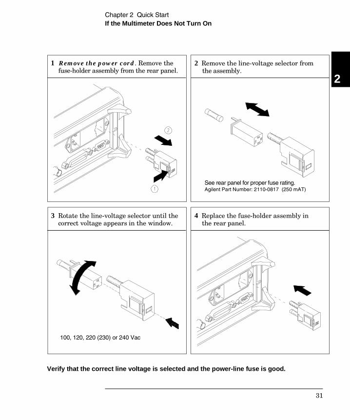
See rear panel for proper fuse rating.Agilent Part Number: 2110-0817 (250 mAT)
100, 120, 220 (230) or 240 Vac
1 Remove the power cord. Remove the fuse-holder assembly from the rear panel.
2 Remove the line-voltage selector from the assembly.
3 Rotate the line-voltage selector until the correct voltage appears in the window.
4 Replace the fuse-holder assembly in the rear panel.
Verify that the correct line voltage is selected and the power-line fuse is good.
2
Chapter 2 Quick Start If the Multimeter Does Not Turn On
31
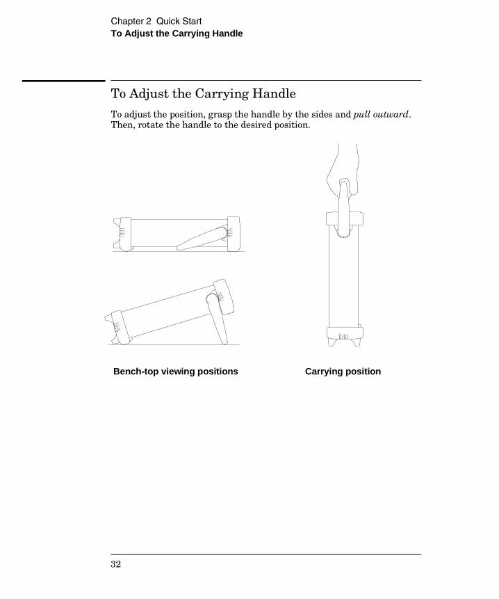
To Adjust the Carrying Handle
To adjust the position, grasp the handle by the sides and pull outward.Then, rotate the handle to the desired position.
Bench-top viewing positions Carrying position
Chapter 2 Quick Start To Adjust the Carrying Handle
32
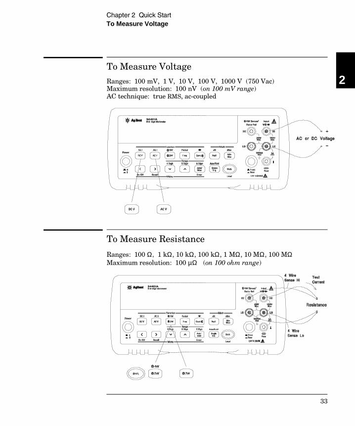
To Measure Voltage
Ranges: 100 mV, 1 V, 10 V, 100 V, 1000 V (750 Vac)Maximum resolution: 100 nV (on 100 mV range)AC technique: true RMS, ac-coupled
To Measure Resistance
Ranges: 100 Ω, 1 kΩ, 10 kΩ, 100 kΩ, 1 MΩ, 10 MΩ, 100 MΩMaximum resolution: 100 µΩ (on 100 ohm range)
2
Chapter 2 Quick Start To Measure Voltage
33
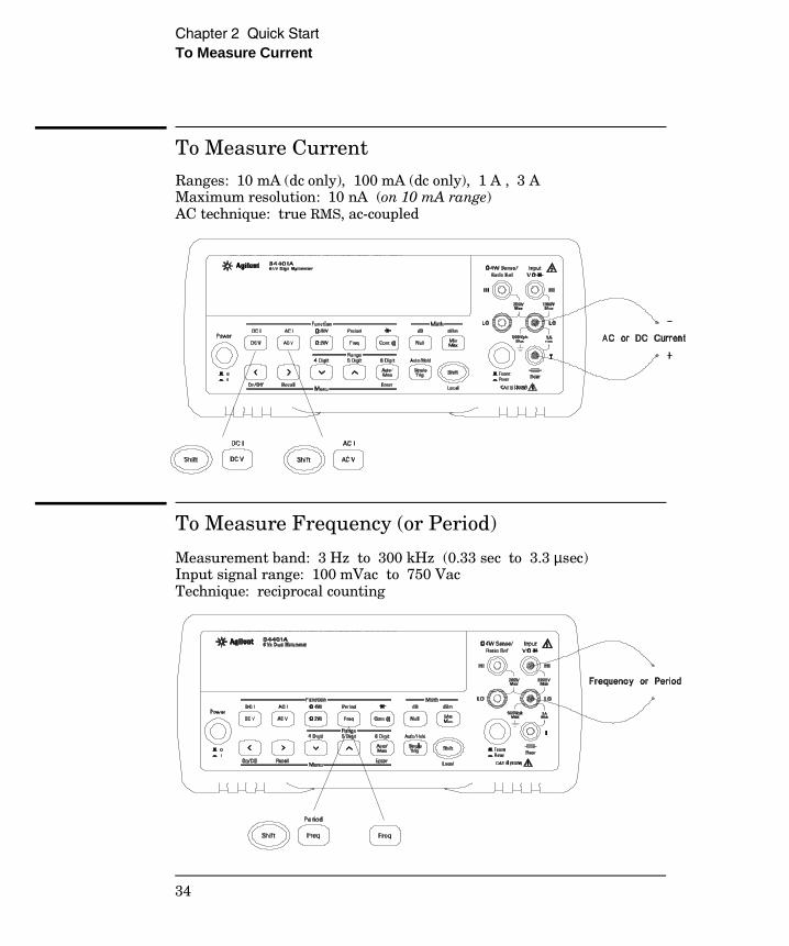
To Measure Current
Ranges: 10 mA (dc only), 100 mA (dc only), 1 A , 3 AMaximum resolution: 10 nA (on 10 mA range)AC technique: true RMS, ac-coupled
To Measure Frequency (or Period)
Measurement band: 3 Hz to 300 kHz (0.33 sec to 3.3 µsec)Input signal range: 100 mVac to 750 VacTechnique: reciprocal counting
Chapter 2 Quick Start To Measure Current
34
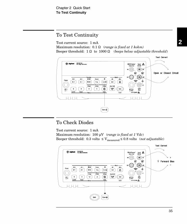
To Test Continuity
Test current source: 1 mAMaximum resolution: 0.1 Ω (range is fixed at 1 kohm)Beeper threshold: 1 Ω to 1000 Ω (beeps below adjustable threshold)
To Check Diodes
Test current source: 1 mAMaximum resolution: 100 µV (range is fixed at 1 Vdc)Beeper threshold: 0.3 volts ≤ Vmeasured ≤ 0.8 volts (not adjustable)
2
Chapter 2 Quick Start To Test Continuity
35
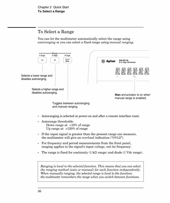
To Select a Range
You can let the multimeter automatically select the range usingautoranging or you can select a fixed range using manual ranging.
• Autoranging is selected at power-on and after a remote interface reset.
• Autorange thresholds: Down range at <10% of range Up range at >120% of range
• If the input signal is greater than the present range can measure,the multimeter will give an overload indication (“OVLD”).
• For frequency and period measurements from the front panel,ranging applies to the signal’s input voltage, not its frequency.
• The range is fixed for continuity (1 kΩ range) and diode (1 Vdc range).
Ranging is local to the selected function. This means that you can selectthe ranging method (auto or manual) for each function independently.When manually ranging, the selected range is local to the function; the multimeter remembers the range when you switch between functions.
Selects a lower range and disables autoranging.
Man annunciator is on when manual range is enabled.
Selects a higher range and disables autoranging.
Toggles between autoranging and manual ranging.
Chapter 2 Quick Start To Select a Range
36
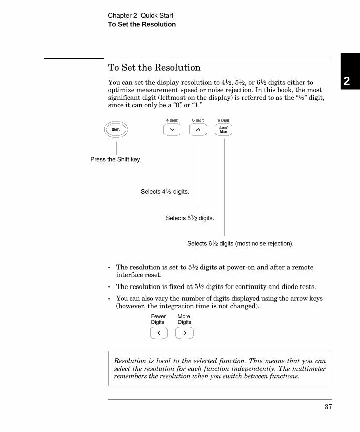
To Set the Resolution
You can set the display resolution to 41⁄2, 51⁄2, or 61⁄2 digits either tooptimize measurement speed or noise rejection. In this book, the mostsignificant digit (leftmost on the display) is referred to as the “1⁄2” digit,since it can only be a “0” or “1.”
• The resolution is set to 51⁄2 digits at power-on and after a remoteinterface reset.
• The resolution is fixed at 51⁄2 digits for continuity and diode tests.
• You can also vary the number of digits displayed using the arrow keys(however, the integration time is not changed).
Resolution is local to the selected function. This means that you canselect the resolution for each function independently. The multimeterremembers the resolution when you switch between functions.
Press the Shift key.
Selects 41⁄2 digits.
Selects 51⁄2 digits.
Selects 61⁄2 digits (most noise rejection).
Fewer MoreDigits Digits
2
Chapter 2 Quick Start To Set the Resolution
37
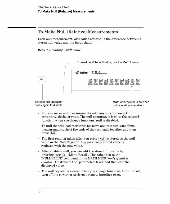
To Make Null (Relative) Measurements
Each null measurement, also called relative, is the difference between astored null value and the input signal.
Result = reading – null value
• You can make null measurements with any function exceptcontinuity, diode, or ratio. The null operation is local to the selectedfunction; when you change functions, null is disabled.
• To null the test lead resistance for more accurate two-wire ohmsmeasurements, short the ends of the test leads together and then press Null .
• The first reading taken after you press Null is stored as the nullvalue in the Null Register. Any previously stored value isreplaced with the new value.
• After enabling null, you can edit the stored null value by pressing Shift > (Menu Recall). This takes you to the“NULL VALUE” command in the MATH MENU (only if null isenabled). Go down to the “parameter” level, and then edit thedisplayed value.
• The null register is cleared when you change functions, turn null off,turn off the power, or perform a remote interface reset.
Enables null operation; Press again to disable.
Math annunciator is on when null operation is enabled.
To read / edit the null value, use the MATH menu
Chapter 2 Quick Start To Make Null (Relative) Measurements
38

To Store Minimum and Maximum Readings
You can store the minimum and maximum readings during a seriesof measurements. The following discussion shows how to read theminimum, maximum, average, and reading count.
• You can use min-max with any function except continuity or diode test.The min-max operation is local to the selected function; when youchange functions, min-max is disabled.
•• After enabling min-max, you can read the stored minimum,maximum, average, and count by pressing Shift > (Menu Recall).This takes you to the “MIN–MAX” command in the MATH MENU(only if min-max is enabled). Go down to the “parameter” level,and then read the values by pressing < or > .
• The stored values are cleared when you turn min-max off, turn off thepower, or perform a remote interface reset.
• The average is of all readings taken since min-max was enabled (notjust the average of the stored minimum and maximum). The count isthe total number of readings taken since min-max was enabled.
Enables min-max operation; Press again to disable.
Math annunciator is on when min-max operation is enabled.
To read the minimum, maximum, average, and count, use the MATH menu.
2
Chapter 2 Quick Start To Store Minimum and Maximum Readings
39
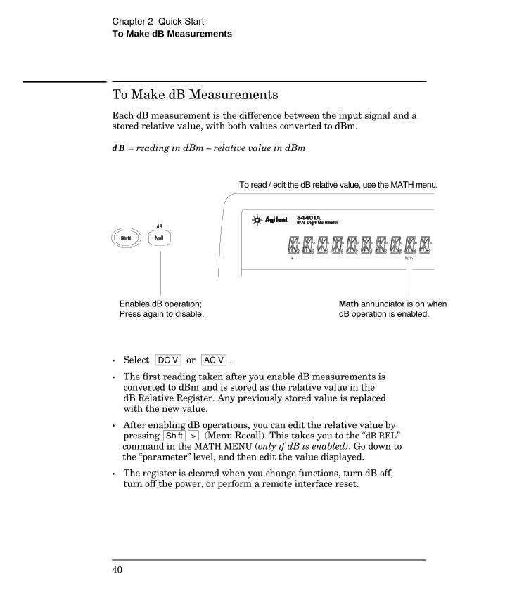
To Make dB Measurements
Each dB measurement is the difference between the input signal and astored relative value, with both values converted to dBm.
dB = reading in dBm – relative value in dBm
• Select DC V or AC V .
• The first reading taken after you enable dB measurements isconverted to dBm and is stored as the relative value in thedB Relative Register. Any previously stored value is replacedwith the new value.
• After enabling dB operations, you can edit the relative value bypressing Shift > (Menu Recall). This takes you to the “dB REL”command in the MATH MENU (only if dB is enabled). Go down tothe “parameter” level, and then edit the value displayed.
• The register is cleared when you change functions, turn dB off,turn off the power, or perform a remote interface reset.
Enables dB operation; Press again to disable.
Math annunciator is on when dB operation is enabled.
To read / edit the dB relative value, use the MATH menu.
Chapter 2 Quick Start To Make dB Measurements
40
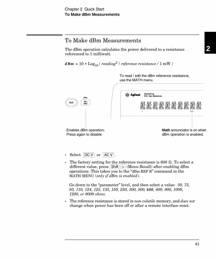
To Make dBm Measurements
The dBm operation calculates the power delivered to a resistancereferenced to 1 milliwatt.
dBm = 10 × Log10 ( reading2 / reference resistance / 1 mW )
• Select DC V or AC V .
• The factory setting for the reference resistance is 600 Ω. To select adifferent value, press Shift > (Menu Recall) after enabling dBmoperations. This takes you to the “dBm REF R” command in theMATH MENU (only if dBm is enabled).
Go down to the “parameter” level, and then select a value: 50, 75,93, 110, 124, 125, 135, 150, 250, 300, 500, 600, 800, 900, 1000,1200, or 8000 ohms.
• The reference resistance is stored in non-volatile memory, and does notchange when power has been off or after a remote interface reset.
Enables dBm operation; Press again to disable.
Math annunciator is on when dBm operation is enabled.
To read / edit the dBm reference resistance, use the MATH menu.
2
Chapter 2 Quick Start To Make dBm Measurements
41
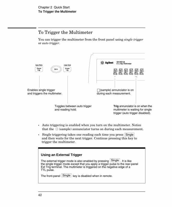
To Trigger the Multimeter
You can trigger the multimeter from the front panel using single triggeror auto trigger.
• Auto triggering is enabled when you turn on the multimeter. Noticethat the ∗ (sample) annunciator turns on during each measurement.
• Single triggering takes one reading each time you press Single and then waits for the next trigger. Continue pressing this key totrigger the multimeter.
Using an External Trigger
The external trigger mode is also enabled by pressing . It is likethe single trigger mode except that you apply a trigger pulse to the rear-panelExt Trig terminal. The multimeter is triggered on the negative edge of aTTL pulse.
The front-panel key is disabled when in remote.
Single
Single
Enables single trigger and triggers the multimeter.
Trig annunciator is on when the multimeter is waiting for single trigger (auto trigger disabled).
∗ (sample) annunciator is on during each measurement.
Toggles between auto trigger and reading hold.
Chapter 2 Quick Start To Trigger the Multimeter
42
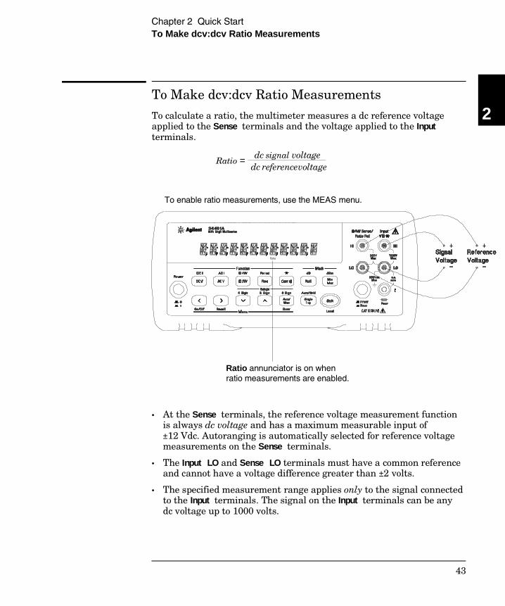
To Make dcv:dcv Ratio Measurements
To calculate a ratio, the multimeter measures a dc reference voltageapplied to the Sense terminals and the voltage applied to the Inputterminals.
• At the Sense terminals, the reference voltage measurement functionis always dc voltage and has a maximum measurable input of±12 Vdc. Autoranging is automatically selected for reference voltagemeasurements on the Sense terminals.
• The Input LO and Sense LO terminals must have a common referenceand cannot have a voltage difference greater than ±2 volts.
• The specified measurement range applies only to the signal connectedto the Input terminals. The signal on the Input terminals can be anydc voltage up to 1000 volts.
Ratio = dc signal voltage dc reference voltage
Ratio annunciator is on when ratio measurements are enabled.
To enable ratio measurements, use the MEAS menu.
2
Chapter 2 Quick Start To Make dcv:dcv Ratio Measurements
43
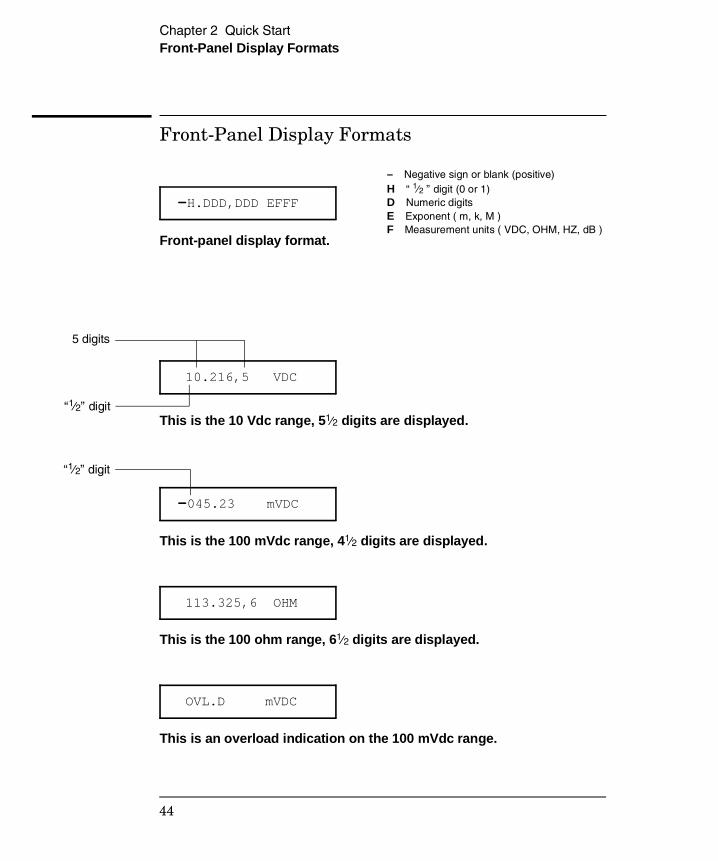
Front-Panel Display Formats
-H.DDD,DDD EFFF
Front-panel display format.
10.216,5 VDC
This is the 10 Vdc range, 51⁄2 digits are displayed.
-045.23 mVDC
This is the 100 mVdc range, 41⁄2 digits are displayed.
113.325,6 OHM
This is the 100 ohm range, 61⁄2 digits are displayed.
OVL.D mVDC
This is an overload indication on the 100 mVdc range.
“1⁄2” digit
5 digits
– Negative sign or blank (positive)H “ 1⁄2 ” digit (0 or 1)D Numeric digitsE Exponent ( m, k, M )F Measurement units ( VDC, OHM, HZ, dB )
“1⁄2” digit
Chapter 2 Quick Start Front-Panel Display Formats
44
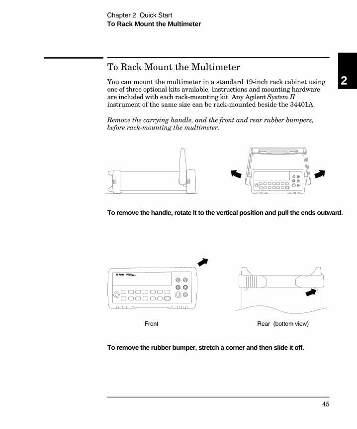
To Rack Mount the Multimeter
You can mount the multimeter in a standard 19-inch rack cabinet usingone of three optional kits available. Instructions and mounting hardwareare included with each rack-mounting kit. Any Agilent System IIinstrument of the same size can be rack-mounted beside the 34401A.
Remove the carrying handle, and the front and rear rubber bumpers,before rack-mounting the multimeter.
To remove the handle, rotate it to the vertical position and pull the ends outward.
Front Rear (bottom view)
To remove the rubber bumper, stretch a corner and then slide it off.
2
Chapter 2 Quick Start To Rack Mount the Multimeter
45
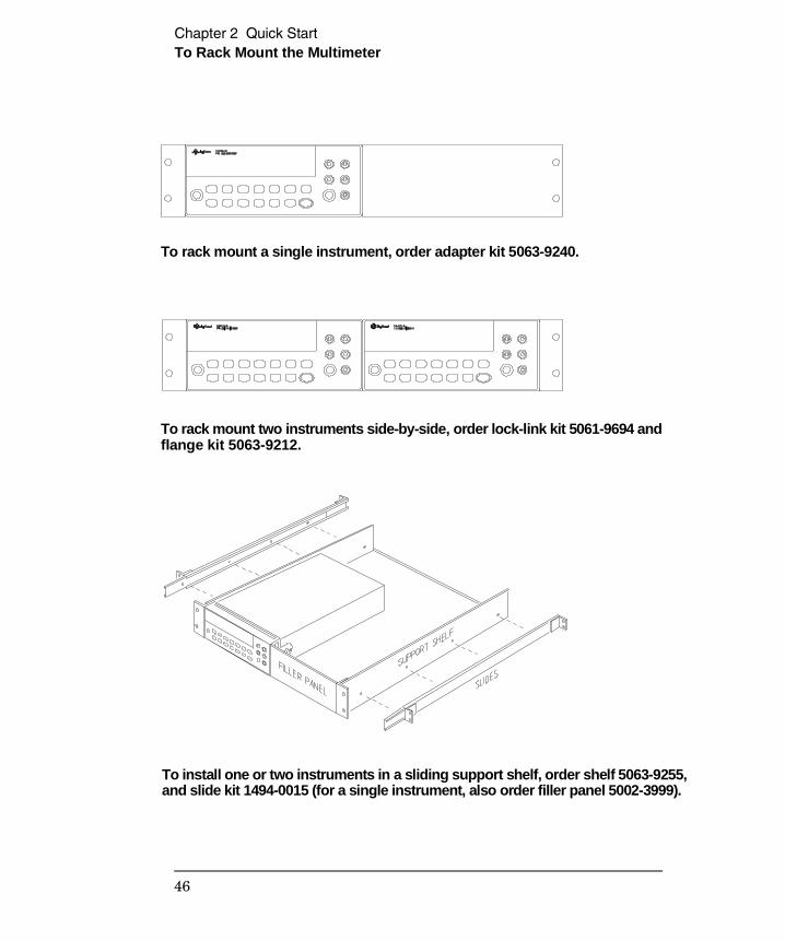
To rack mount a single instrument, order adapter kit 5063-9240.
To rack mount two instruments side-by-side, order lock-link kit 5061-9694 and flange kit 5063-9212.
To install one or two instruments in a sliding support shelf, order shelf 5063-9255, and slide kit 1494-0015 (for a single instrument, also order filler panel 5002-3999).
Chapter 2 Quick Start To Rack Mount the Multimeter
46
3
Menu Tutorial
3
Menu Tutorial
By now you should be familiar with the FUNCTION and RANGE / DIGITSgroups of front-panel keys. You should also understand how to makefront-panel connections for the various types of measurements. If youare not familiar with this information, we recommend that you readchapter 2, “Quick Start,” starting on page 27.
This chapter introduces you to the front panel menu. It describes eachmenu and takes you step-by-step through calibration examples.See chapter 3, “Features and Functions” in the User’s Guide for acomplete discussion of the multimeter’s capabilities and operation.
48
Front-Panel Menu Reference
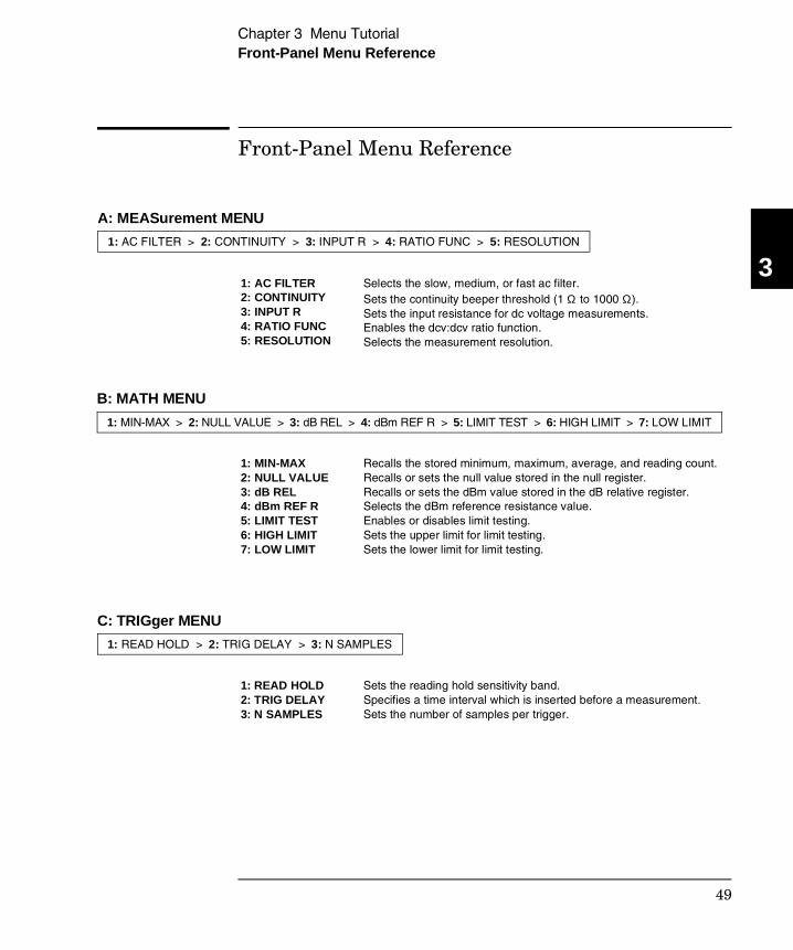
1: AC FILTER 2: CONTINUITY 3: INPUT R 4: RATIO FUNC 5: RESOLUTION
Selects the slow, medium, or fast ac filter. Sets the continuity beeper threshold (1 Ω to 1000 Ω). Sets the input resistance for dc voltage measurements. Enables the dcv:dcv ratio function. Selects the measurement resolution.
1: MIN-MAX 2: NULL VALUE 3: dB REL 4: dBm REF R 5: LIMIT TEST 6: HIGH LIMIT 7: LOW LIMIT
Recalls the stored minimum, maximum, average, and reading count. Recalls or sets the null value stored in the null register. Recalls or sets the dBm value stored in the dB relative register. Selects the dBm reference resistance value. Enables or disables limit testing. Sets the upper limit for limit testing. Sets the lower limit for limit testing.
1: READ HOLD 2: TRIG DELAY 3: N SAMPLES
Sets the reading hold sensitivity band. Specifies a time interval which is inserted before a measurement. Sets the number of samples per trigger.
A: MEASurement MENU
1: AC FILTER > 2: CONTINUITY > 3: INPUT R > 4: RATIO FUNC > 5: RESOLUTION
B: MATH MENU
1: MIN-MAX > 2: NULL VALUE > 3: dB REL > 4: dBm REF R > 5: LIMIT TEST > 6: HIGH LIMIT > 7: LOW LIMIT
C: TRIGger MENU
1: READ HOLD > 2: TRIG DELAY > 3: N SAMPLES
3
Chapter 3 Menu Tutorial Front-Panel Menu Reference
49
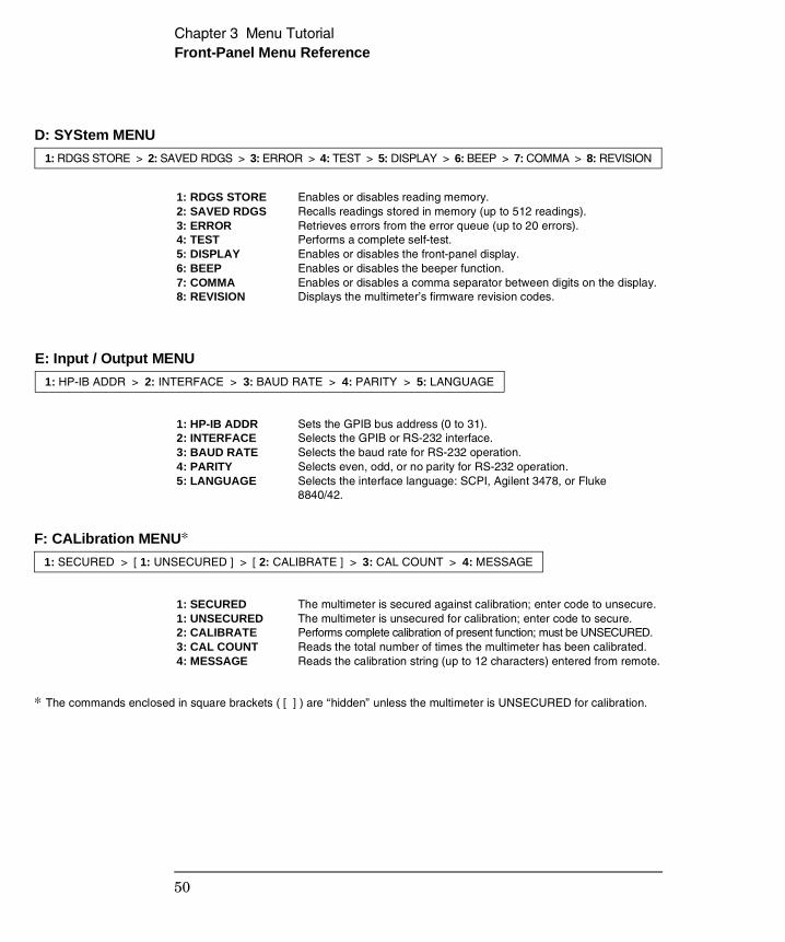
1: RDGS STORE 2: SAVED RDGS 3: ERROR 4: TEST 5: DISPLAY 6: BEEP 7: COMMA 8: REVISION
Enables or disables reading memory. Recalls readings stored in memory (up to 512 readings). Retrieves errors from the error queue (up to 20 errors). Performs a complete self-test. Enables or disables the front-panel display. Enables or disables the beeper function. Enables or disables a comma separator between digits on the display. Displays the multimeter’s firmware revision codes.
1: HP-IB ADDR 2: INTERFACE 3: BAUD RATE 4: PARITY 5: LANGUAGE
Sets the GPIB bus address (0 to 31). Selects the GPIB or RS-232 interface. Selects the baud rate for RS-232 operation. Selects even, odd, or no parity for RS-232 operation. Selects the interface language: SCPI, Agilent 3478, or Fluke8840/42.
1: SECURED 1: UNSECURED 2: CALIBRATE 3: CAL COUNT 4: MESSAGE
The multimeter is secured against calibration; enter code to unsecure. The multimeter is unsecured for calibration; enter code to secure. Performs complete calibration of present function; must be UNSECURED.Reads the total number of times the multimeter has been calibrated. Reads the calibration string (up to 12 characters) entered from remote.
F: CALibration MENU*
1: SECURED > [ 1: UNSECURED ] > [ 2: CALIBRATE ] > 3: CAL COUNT > 4: MESSAGE
* The commands enclosed in square brackets ( [ ] ) are “hidden” unless the multimeter is UNSECURED for calibration.
D: SYStem MENU
1: RDGS STORE > 2: SAVED RDGS > 3: ERROR > 4: TEST > 5: DISPLAY > 6: BEEP > 7: COMMA > 8: REVISION
E: Input / Output MENU
1: HP-IB ADDR > 2: INTERFACE > 3: BAUD RATE > 4: PARITY > 5: LANGUAGE
Chapter 3 Menu Tutorial Front-Panel Menu Reference
50
A Front-Panel Menu Tutorial
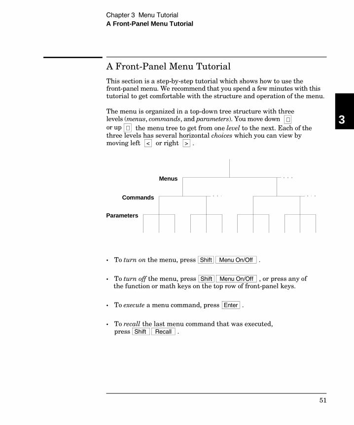
This section is a step-by-step tutorial which shows how to use thefront-panel menu. We recommend that you spend a few minutes with thistutorial to get comfortable with the structure and operation of the menu.
The menu is organized in a top-down tree structure with three levels (menus, commands, and parameters). You move down ∨ or up ∧ the menu tree to get from one level to the next. Each of thethree levels has several horizontal choices which you can view bymoving left < or right > .
• To turn on the menu, press Shift Menu On/Off .
• To turn off the menu, press Shift Menu On/Off , or press any ofthe function or math keys on the top row of front-panel keys.
• To execute a menu command, press Enter .
• To recall the last menu command that was executed, press Shift Recall .
Menus
Parameters
Commands
3
Chapter 3 Menu Tutorial A Front-Panel Menu Tutorial
51
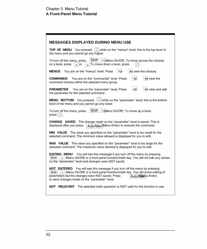
MESSAGES DISPLAYED DURING MENU USE
TOP OF MENU You pressed while on the “menus” level; this is the top level ofthe menu and you cannot go any higher.
To turn off the menu, press (Menu On/Off). To move across the choiceson a level, press or . To move down a level, press .
MENUS You are on the “menus” level. Press or to view the choices.
COMMANDS You are on the “commands” level. Press or to view thecommand choices within the selected menu group.
PARAMETER You are on the “parameter” level. Press or to view and editthe parameter for the selected command.
MENU BOTTOM You pressed while on the “parameter” level; this is the bottomlevel of the menu and you cannot go any lower.
To turn off the menu, press (Menu On/Off). To move up a level, press .
CHANGE SAVED The change made on the “parameter” level is saved. This isdisplayed after you press (Menu Enter) to execute the command.
MIN VALUE The value you specified on the “parameter” level is too small for theselected command. The minimum value allowed is displayed for you to edit.
MAX VALUE The value you specified on the “parameter” level is too large for theselected command. The maximum value allowed is displayed for you to edit.
EXITING MENU You will see this message if you turn off the menu by pressing (Menu On/Off) or a front-panel function/math key. You did not edit any valueson the “parameter” level and changes were NOT saved.
NOT ENTERED You will see this message if you turn off the menu by pressing (Menu On/Off) or a front-panel function/math key. You did some editing ofparameters but the changes were NOT saved. Press (Menu Enter) to save changes made on the “parameter” level.
NOT RELEVANT The selected math operation is NOT valid for the function in use.
∨
∧
∧
∨
< > Shift <
Auto/Man
< >
< >
< >
Shift <
Shift
Auto/Man
<
Shift <
Chapter 3 Menu Tutorial A Front-Panel Menu Tutorial
52
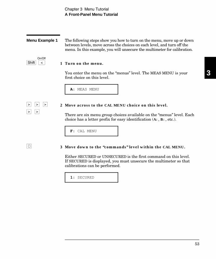
Menu Example 1 The following steps show you how to turn on the menu, move up or downbetween levels, move across the choices on each level, and turn off themenu. In this example, you will unsecure the multimeter for calibration.
1 Turn on the menu.
You enter the menu on the “menus” level. The MEAS MENU is yourfirst choice on this level.
A: MEAS MENU
2 Move across to the CAL MENU choice on this level.
There are six menu group choices available on the “menus” level. Eachchoice has a letter prefix for easy identification (A: , B: , etc.).
F: CAL MENU
3 Move down to the “commands” level within the CAL MENU.
Either SECURED or UNSECURED is the first command on this level.If SECURED is displayed, you must unsecure the multimeter so thatcalibrations can be performed.
1: SECURED
∨
Shift < On/Off
>
>
> >
>
3
Chapter 3 Menu Tutorial A Front-Panel Menu Tutorial
53
4 Move down to the “parameters” level.
The multimeter will wait for the security code to be entered.
^000000 CODE
5 Unsecure the multimeter by entering the security code.
The security code is set to “HP034401” when the multimeter is shippedfrom the factory. The security code is stored in non-volatile memory, anddoes not change when power has been off or after a remote interface reset.
Use < and > to move left or right between digits. Use ∧ or ∨ to increment or decrement numbers.
If you have not changed the security code from its factory setting, youcan unsecure the multimeter by entering “034401” from the front panel.Only the last six characters are recognized from the front panel andthey must be numeric characters only.
^034401 CODE
We recommend that you use a unique SECURE code for each multimeterto obtain the maximum benefit from the electronic calibration securityfeatures of the multimeter.
To secure the multimeter again, return to the parameter level of theUNSECURED command and enter a new security code.
For further information on the calibration security features of the multimeter, see “Calibration Security Code” on page 73.
∨
4 3 0
1 0 4
Auto/Man ENTER
Chapter 3 Menu Tutorial A Front-Panel Menu Tutorial
54

Menu Example 2 Some commands in the menu require that you enter a numeric parametervalue. The following steps show you how to enter a number in the menu.In this example, you will set the calibration value to 0.0 volts. For thisexample you must apply a short between HI-LO Sense and HI-LO Input.
Caution Completing this example will perform a zero calibration. Referto chapter 4, “Calibration Procedures,” before attempting this example.
1 Turn on the menu.
You enter the menu on the “menus” level. The MEAS MENU is your firstchoice on this level.
A: MEAS MENU
2 Move across to the CAL MENU choice on this level.
There are six menu group choices available on the “menus” level. Eachchoice has a letter prefix for easy identification (A: , B: , etc.).
F: CAL MENU
<
Shift < On/Off
3
Chapter 3 Menu Tutorial A Front-Panel Menu Tutorial
55

3 Move down to the “commands” level within the CAL MENU.
Either SECURED or UNSECURED is the first command on this level.To perform a calibration, UNSECURED must be displayed. If SECUREDis displayed, see example 1 in this chapter to unsecure for calibration.
1: UNSECURED
4 Move across to the CALIBRATE command on this level.
There are four command choices available in the CAL MENU. Each choiceon this level has a number prefix for easy identification (1: , 2: , etc.).
2: CALIBRATE
5 Move down to edit the CALIBRATE VALUE parameter.
The calibration value should read 100.000,0 mVDC when you come tothis point in the menu for the first time (when set to 100 mVdc range).For this example, you will set the calibration value to 0.0 volts.
∧ 100.000,0 mVDC
When you see the flashing “∧ ” on the left side of the display, you canabort the edit and return to the “commands” level by pressing ∧ .
6 Move the flashing cursor over to edit the first digit.
Notice that the leftmost digit is flashing.
100.000,0 mVDC
>
∨
>
∨
Chapter 3 Menu Tutorial A Front-Panel Menu Tutorial
56
7 Decrement the first digit until “0” is displayed.
You decrement or increment each digit independently. Neighboringdigits are not affected.
000.000,0 mVDC
8 Move the flashing cursor over to the “units” location.
Notice that the units are flashing on the right side of the display.
000.000,0 mVDC
9 Increase the displayed number by a factor of 10.
Notice that the position of the decimal point changes and the displayednumber increases by a factor of 10.
0.000,000 VDC
10 Save the change and turn off the menu.
The multimeter beeps and displays a message to show that the changeis now in effect. You are then exited from the menu.
The zero offset calibration procedure determines new calibration constants for each function and range. Separate calibration is requiredfor the front and rear terminals.
< <
∧
∨
Auto/Man ENTER
3
Chapter 3 Menu Tutorial A Front-Panel Menu Tutorial
57

58
4
CalibrationProcedures
4
Calibration Procedures
• Agilent Calibration Services 61• Calibration Interval 61• Time Required for Calibration 61• Automating Calibration Procedures 62• Recommended Test Equipment 63• Test Considerations 64• Performance Verification Tests 65• Zero Offset Verification 67• Gain Verification 69• Optional AC Performance Verification Tests 72• Calibration Security Code 73• Calibration Count 75• Calibration Message 75• Calibration Procedures 76• Aborting a Calibration in Progress 76• Zero Adjustment 77• Gain Adjustment 79• Optional Gain Calibration Procedures 82• Understanding the AC Signal Filter 85• Understanding Resolution 86• Error Messages 89
The performance verification tests use the multimeter’s specificationslisted in chapter 1, “Specifications,” starting on page 11.
Closed-Case Electronic Calibration The multimeter featuresclosed-case electronic calibration since there are no internal mechanicaladjustments required. The multimeter automatically prompts you forthe required full-scale input when performing a range calibration.The multimeter measures the applied input and calculates correctionfactors based upon the input reference value you specify. The newcorrection factors are stored in non-volatile memory until the nextcalibration adjustment is performed. (Non-volatile memory does notchange when power has been off or after a remote interface reset.)
60
Agilent Calibration Services
When your multimeter is due for calibration, contact your local AgilentService Center for a low-cost recalibration. The 34401A Multimeter issupported on automated calibration systems which allow Agilent toprovide this service at competitive prices. Calibrations to MIL-STD-45662are also available at competitive prices.
Calibration Interval
The multimeter should be calibrated on a regular interval determinedby the measurement accuracy requirements of your application.A 90-day interval is recommended for the most demanding applications,while a 1-year or 2-year interval may be adequate for less demandingapplications. Agilent does not recommend extending calibrationintervals beyond 2 years for any application.
Whatever calibration interval you select, Agilent recommends thatcomplete re-adjustment should always be performed at the calibrationinterval. This will increase your confidence that the Agilent 34401A willremain within specification for the next calibration interval. Thiscriteria for re-adjustment provides the best measure of the multimeter’slong-term stability. Performance data measured using this method caneasily be used to extend future calibration intervals.
Time Required for Calibration
The Agilent 34401A can be automatically calibrated under computercontrol. With computer control you can perform the complete calibrationprocedure and performance verification tests in less than 20 minutes.Manual calibrations using a multi-function calibrator will takeapproximately 40 minutes.
4
Chapter 4 Calibration ProceduresAgilent Calibration Services
61
Automating Calibration Procedures
You can automate the complete verification and adjustment proceduresoutlined in this chapter if you have access to programmable standards,such as a multi-function calibrator. You can program the instrumentconfigurations specified for each test over the remote interface. You canthen enter readback verification data into a test program and comparethe results to the appropriate test limit values.
If you are using the Agilent 34401A in the Fluke 8840A/8842Aemulation mode, you cannot use the Fluke calibration commands. Youmust use the SCPI calibration commands described in chapter 4 of theAgilent 34401A User’s Guide.
You can also adjust the multimeter from the remote interface. Remoteadjustment is similar to the local front-panel procedure. You can usea computer to perform the adjustment by first selecting the requiredfunction and range. The calibration value is sent to the multimeter andthen the calibration is initiated over the remote interface. The multimetermust be unsecured prior to initiating the calibration procedure.
For further details on programming the multimeter, see chapter 3 andchapter 4 in the Agilent 34401A User’s Guide.
Chapter 4 Calibration ProceduresAutomating Calibration Procedures
62
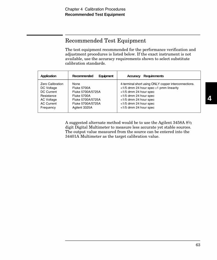
Recommended Test Equipment
The test equipment recommended for the performance verification andadjustment procedures is listed below. If the exact instrument is notavailable, use the accuracy requirements shown to select substitutecalibration standards.
A suggested alternate method would be to use the Agilent 3458A 81⁄2digit Digital Multimeter to measure less accurate yet stable sources.The output value measured from the source can be entered into the34401A Multimeter as the target calibration value.
Application
Zero CalibrationDC VoltageDC CurrentResistanceAC VoltageAC CurrentFrequency
Recommended Equipment
None Fluke 5700AFluke 5700A/5725AFluke 5700AFluke 5700A/5725AFluke 5700A/5725AAgilent 3325A
Accuracy Requirements
4-terminal short using ONLY copper interconnections. <1/5 dmm 24 hour spec ±1 pmm linearity <1/5 dmm 24 hour spec <1/5 dmm 24 hour spec <1/5 dmm 24 hour spec <1/5 dmm 24 hour spec <1/5 dmm 24 hour spec
4
Chapter 4 Calibration ProceduresRecommended Test Equipment
63
Test Considerations
To ensure proper instrument operation, verify that you have selectedthe correct power-line voltage prior to attempting any test procedure inthis chapter. See chapter 2, “Quick Start,” for more information.
Ensure that all measurement terminal connections (both front paneland rear panel) are removed while the multimeter’s internal self-test isbeing performed. Errors may be induced by ac signals present on themultimeter’s input terminals during a self-test. Long test leads can alsoact as an antenna causing pick-up of ac signals.
For optimum performance, all test procedures should comply with thefollowing recommendations:
• Assure that the calibration ambient temperature is stable andbetween 18°C and 28°C.
• Assure ambient relative humidity is less than 80%.
• Allow a 2-hour warm-up period before verification or adjustment.
• Use only copper connections to minimize thermal offset voltages.
• Use shielded twisted PTFE insulated cable to minimize highresistance errors.
• Keep cables as short as possible.
• Allow 5 minutes after handling input connections for thermal offsetvoltage settling.
Because the multimeter is capable of making highly accuratemeasurements, you must take special care to ensure that the calibrationstandards and test procedures used do not introduce additional errors.Ideally, the standards used to test and calibrate the multimeter shouldbe an order of magnitude more accurate than each multimeter range fullscale error specification.
For dc voltage, dc current, and resistance measurements, you shouldtake care to ensure that the calibrator’s “0” output is correct. If necessary,the multimeter measurements can be referenced to the calibrator’s “0”output using the multimeter’s front-panel NULL function. You will needto repeat this procedure for each range of the measuring function beingverified.
Chapter 4 Calibration ProceduresTest Considerations
64
Performance Verification Tests
You can perform three different levels of performance verification tests:
• Self-Test A series of internal verification tests that give a highconfidence that the multimeter is operational.
• Quick Verification A combination of the internal self-tests andselected verification tests.
• Performance Verification Tests An extensive set of tests that arerecommended as an acceptance test when you first receive themultimeter or after performing adjustments.
Self-Test
A brief power-on self-test occurs automatically whenever you turn onthe multimeter. This limited test assures that the multimeter is capableof operation.
To perform a complete self-test, including over 25 tests, hold downthe Shift key as you press the Power switch to turn on the multimeter;hold down the key for more than 5 seconds (a complete description ofthese tests can be found in chapter 6.) The multimeter meter willautomatically perform the complete self-test procedure when yourelease the key. The self-test will complete in approximately 20 seconds.
You can perform many tests individually (or all tests at once) using theTEST command in the SYS MENU. You can also perform a self-test fromthe remote interface. For further information, see chapter 3 in theAgilent 34401A User’s Guide.
• If the self-test is successful, “PASS” is displayed on the front panel.
• If the self-test fails, “FAIL” is displayed and the ERROR annunciatorturns on. If repair is required, see chapter 6, “Service,” for further details.
• If all tests pass, you can have a high confidence (90%) that themultimeter is operational.
4
Chapter 4 Calibration ProceduresPerformance Verification Tests
65
Quick Performance CheckThe quick performance check is a combination of internal self-test andan abbreviated performance test (specified by the letter Q in theperformance verification tests). This test provides a simple method toachieve high confidence in the multimeter’s ability to functionallyoperate and meet specifications. These tests represent the absoluteminimum set of performance checks recommended following any serviceactivity. Auditing the multimeter’s performance for the quick checkpoints (designated by a Q) verifies performance for “normal” accuracy driftmechanisms. This test does not check for abnormal component failures.
To perform the quick performance check, do the following:
• Perform a complete self-test.
• Perform only the performance verification tests indicated with theletter Q.
If the multimeter fails the quick performance check, adjustment or repairis required.
Performance Verification TestsThe performance verification tests are recommended as acceptance testswhen you first receive the multimeter. The acceptance test resultsshould be compared against the 90-day test limits. You should use the24-hour test limits only for verification within 24 hours after performingthe adjustment procedure. After acceptance, you should repeat theperformance verification tests with the next calibration interval.
If the multimeter fails performance verification, adjustment or repairis required.
ALL configurations shown assume that the multimeter starts from itspower-on or remote reset state.
Chapter 4 Calibration ProceduresPerformance Verification Tests
66
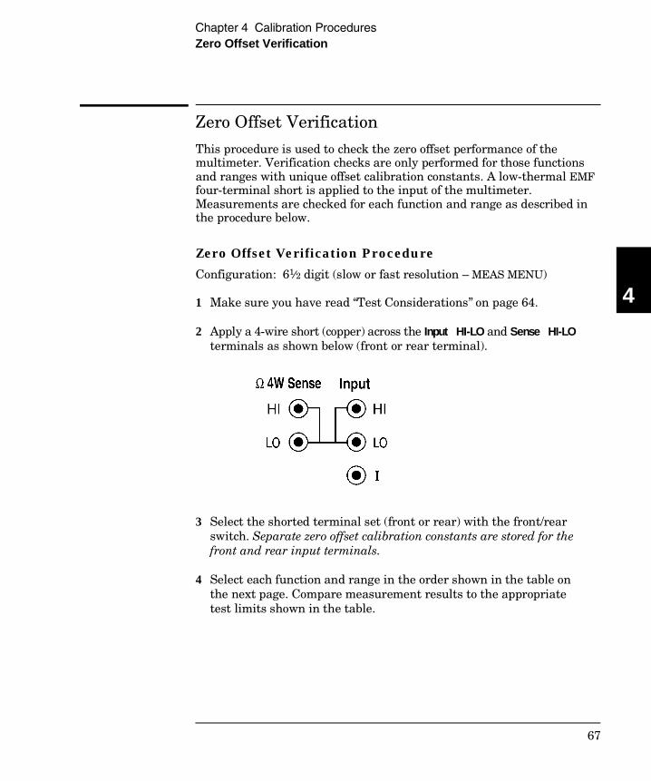
Zero Offset Verification
This procedure is used to check the zero offset performance of themultimeter. Verification checks are only performed for those functionsand ranges with unique offset calibration constants. A low-thermal EMFfour-terminal short is applied to the input of the multimeter.Measurements are checked for each function and range as described inthe procedure below.
Zero Offset Verification Procedure
Configuration: 61⁄2 digit (slow or fast resolution – MEAS MENU)
1 Make sure you have read “Test Considerations” on page 64.
2 Apply a 4-wire short (copper) across the Input HI-LO and Sense HI-LOterminals as shown below (front or rear terminal).
3 Select the shorted terminal set (front or rear) with the front/rearswitch. Separate zero offset calibration constants are stored for thefront and rear input terminals.
4 Select each function and range in the order shown in the table onthe next page. Compare measurement results to the appropriatetest limits shown in the table.
4
Chapter 4 Calibration ProceduresZero Offset Verification
67

Caution Zero offset calibration using a multifunction calibrator is NOTrecommended. The calibrator and cabling offset can be large and unstablecausing poor offset calibration of the Agilent 34401A or any multimeter.
Note These offset tests should be verified for both the front and the rearinput terminals.
Input (Front/Rear)
Function
QuickCheck
34401A Range
Error From Nominal
24 hour 90 day 1 year
Open Open Open Open
Short Short Short Short Short
Short Short Short Short Short Short Short
DC Current
DC Volts
2-WireOhms[1] and4-WireOhms
Q
Q
Q
10 mA 100 mA 1 A 3 A
100 mV 1 V 10 V 100 V 1000 V
100 Ω 1 kΩ 10 kΩ 100 kΩ 1 MΩ 10 MΩ 100 MΩ
±1 µA±4 µA±60 µA ±600 µA
±3 µV±6 µV±40 µV±600 µV±6 mV
±3 mΩ±5 mΩ±50 mΩ±500 mΩ±10 Ω±100 Ω±10 kΩ
±2 µA±5 µA±100 µA ±600 µA
±3.5 µV±7 µV±50 µV±600 µV±10 mV
±4 mΩ±10 mΩ±100 mΩ±1 Ω±10 Ω±100 Ω±10 kΩ
±2 µA±5 µA±100 µA ±600 µA
±3.5 µV±7 µV±50 µV±600 µV±10 mV
±4 mΩ±10 mΩ±100 mΩ±1 Ω±10 Ω±100 Ω±10 kΩ
[1] For 2-wire ohms, these errors assume you are using Math Null. Without Math Null, an additional 200 mΩ of error must be added.Q: Quick performance verification test points.
Chapter 4 Calibration ProceduresZero Offset Verification
68
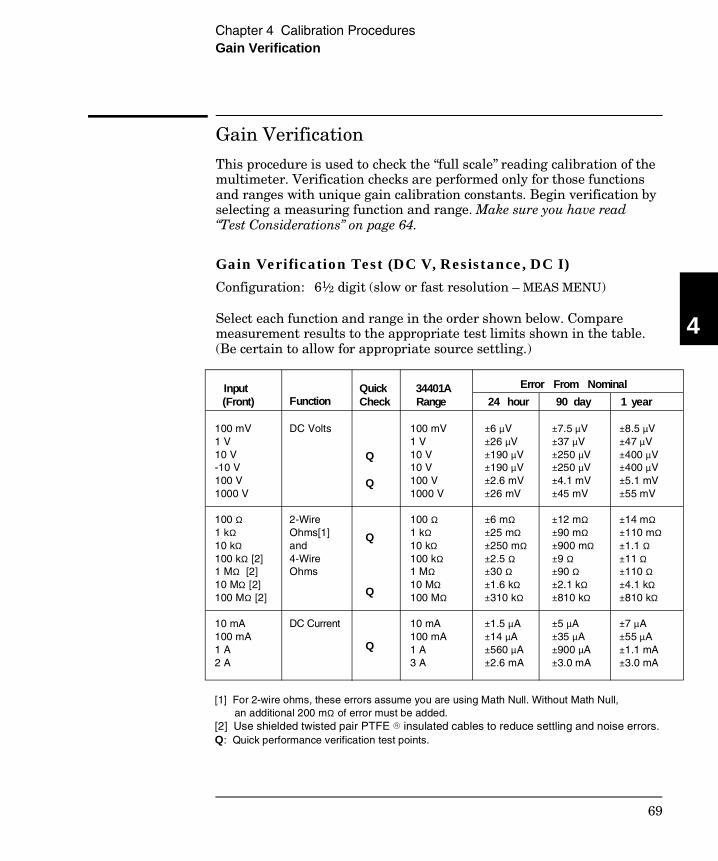
Gain Verification
This procedure is used to check the “full scale” reading calibration of themultimeter. Verification checks are performed only for those functionsand ranges with unique gain calibration constants. Begin verification byselecting a measuring function and range. Make sure you have read“Test Considerations” on page 64.
Gain Verification Test (DC V, Resistance, DC I) Configuration: 61⁄2 digit (slow or fast resolution – MEAS MENU)
Select each function and range in the order shown below. Comparemeasurement results to the appropriate test limits shown in the table.(Be certain to allow for appropriate source settling.)
Input (Front)
Function
QuickCheck
34401A Range
Error From Nominal
24 hour 90 day 1 year
100 mV 1 V10 V-10 V100 V1000 V
100 Ω1 kΩ10 kΩ100 kΩ [2]1 MΩ [2]10 MΩ [2]100 MΩ [2]
10 mA 100 mA 1 A2 A
DC Volts
2-WireOhms[1]and4-WireOhms
DC Current
Q
Q
Q
Q
Q
100 mV 1 V 10 V 10 V 100 V 1000 V
100 Ω 1 kΩ 10 kΩ100 kΩ1 MΩ10 MΩ100 MΩ
10 mA 100 mA 1 A 3 A
±6 µV±26 µV±190 µV±190 µV±2.6 mV ±26 mV
±6 mΩ±25 mΩ±250 mΩ±2.5 Ω±30 Ω±1.6 kΩ±310 kΩ
±1.5 µA±14 µA±560 µA ±2.6 mA
±7.5 µV±37 µV±250 µV±250 µV ±4.1 mV ±45 mV
±12 mΩ±90 mΩ±900 mΩ±9 Ω±90 Ω±2.1 kΩ±810 kΩ
±5 µA±35 µA±900 µA ±3.0 mA
±8.5 µV ±47 µV±400 µV±400 µV±5.1 mV ±55 mV
±14 mΩ±110 mΩ±1.1 Ω±11 Ω±110 Ω±4.1 kΩ±810 kΩ
±7 µA±55 µA±1.1 mA ±3.0 mA
[1] For 2-wire ohms, these errors assume you are using Math Null. Without Math Null, an additional 200 mΩ of error must be added.[2] Use shielded twisted pair PTFE insulated cables to reduce settling and noise errors.Q: Quick performance verification test points.
4
Chapter 4 Calibration ProceduresGain Verification
69
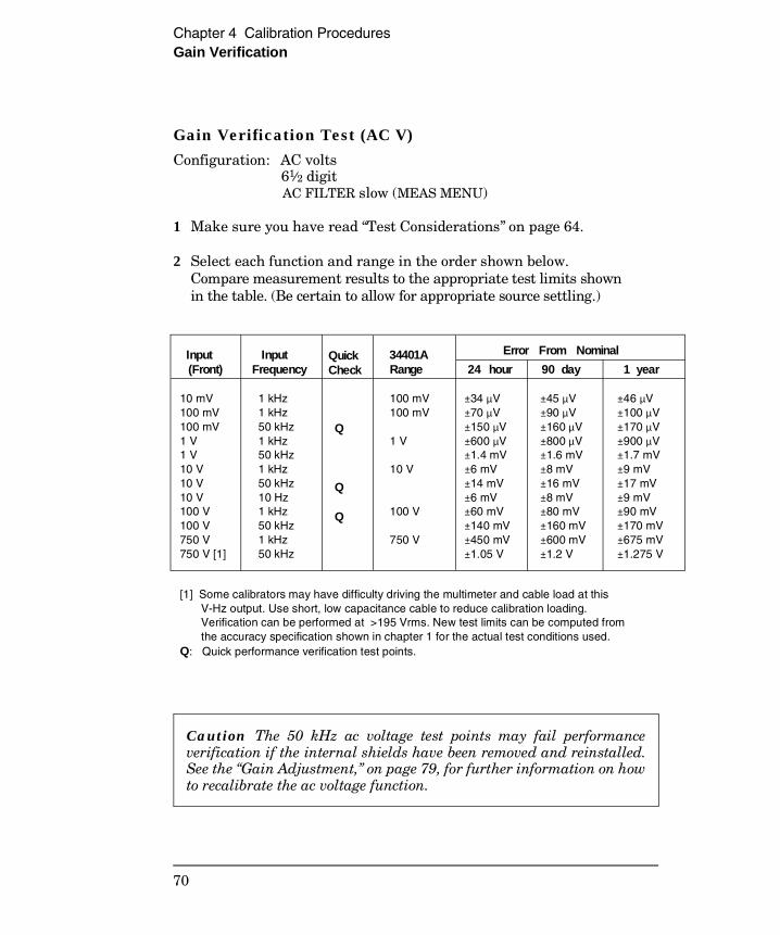
Gain Verification Test (AC V) Configuration: AC volts
61⁄2 digit AC FILTER slow (MEAS MENU)
1 Make sure you have read “Test Considerations” on page 64.
2 Select each function and range in the order shown below.Compare measurement results to the appropriate test limits shownin the table. (Be certain to allow for appropriate source settling.)
Caution The 50 kHz ac voltage test points may fail performanceverification if the internal shields have been removed and reinstalled.See the “Gain Adjustment,” on page 79, for further information on howto recalibrate the ac voltage function.
Input (Front)
Input Frequency
QuickCheck
34401A Range
Error From Nominal
24 hour 90 day 1 year
10 mV100 mV100 mV1 V1 V10 V10 V10 V100 V100 V750 V750 V [1]
1 kHz 1 kHz 50 kHz 1 kHz 50 kHz 1 kHz 50 kHz 10 Hz 1 kHz 50 kHz 1 kHz 50 kHz
Q
Q
Q
100 mV 100 mV
1 V
10 V
100 V
750 V
±34 µV ±70 µV±150 µV ±600 µV ±1.4 mV ±6 mV ±14 mV ±6 mV ±60 mV ±140 mV ±450 mV ±1.05 V
±45 µV ±90 µV±160 µV ±800 µV ±1.6 mV ±8 mV ±16 mV ±8 mV ±80 mV ±160 mV ±600 mV ±1.2 V
±46 µV ±100 µV ±170 µV ±900 µV ±1.7 mV ±9 mV ±17 mV ±9 mV ±90 mV ±170 mV ±675 mV ±1.275 V
[1] Some calibrators may have difficulty driving the multimeter and cable load at this V-Hz output. Use short, low capacitance cable to reduce calibration loading. Verification can be performed at >195 Vrms. New test limits can be computed from the accuracy specification shown in chapter 1 for the actual test conditions used.Q: Quick performance verification test points.
Chapter 4 Calibration ProceduresGain Verification
70
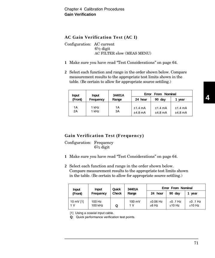
AC Gain Verification Test (AC I) Configuration: AC current
61⁄2 digit AC FILTER slow (MEAS MENU)
1 Make sure you have read “Test Considerations” on page 64.
2 Select each function and range in the order shown below. Comparemeasurement results to the appropriate test limits shown in thetable. (Be certain to allow for appropriate source settling.)
Gain Verification Test (Frequency)
Configuration: Frequency 61⁄2 digit
1 Make sure you have read “Test Considerations” on page 64.
2 Select each function and range in the order shown below.Compare measurement results to the appropriate test limits shownin the table. (Be certain to allow for appropriate source settling.)
Input (Front)
Input Frequency
34401A Range
Error From Nominal
24 hour 90 day 1 year
1A 2A
1 kHz 1 kHz
1A 3A
±1.4 mA
±4.8 mA
±1.4 mA
±4.8 mA
±1.4 mA
±4.8 mA
Input (Front)
Input Frequency
Quick Check
34401A Range
Error From Nominal
24 hour 90 day 1 year
10 mV [1]1 V
100 Hz100 kHz Q
100 mV 1 V
±0.06 Hz±6 Hz
±0 .1 Hz±10 Hz
±0 .1 Hz±10 Hz
[1] Using a coaxial input cable.Q: Quick performance verification test points.
4
Chapter 4 Calibration ProceduresGain Verification
71

Optional AC Performance Verification Tests
These tests are not intended to be performed with every calibration.They are provided as an aid for verifying additional instrumentspecifications. There are no adjustments for these tests; they areprovided for performance verification only.
Configuration: AC volts 61⁄2 digit AC FILTER slow (MEAS MENU)
1 Make sure you have read “Test Considerations” on page 64.
2 Select each function and range in the order shown below.Compare measurement results to the appropriate test limits shownin the table. (Be certain to allow for appropriate source settling.)
Input (Front)
Input Frequency
34401A Range
Error From Nominal
24 hour 90 day 1 year
1 V 1 V 1 V 1 V 1 V 1 V
10 V 1 V 100 mV
20 Hz 1 kHz 20 kHz 50 kHz 100 kHz 300 kHz
1 kHz 1 kHz 1 kHz
1 V 1 V 1 V 1 V 1 V 1 V
10 V 10 V 10 V
±600 µV ±600 µV ±600 µV ±1.4 mV ±6.3 mV ±45 mV
±6 mV ±2.4 mV ±12 mV
±800 µV ±800 µV ±800 µV ±1.6 mV ±6.8 mV ±45 mV
±8 mV ±3.5 mV ±13 mV
±900 µV ±900 µV ±900 µV ±1.7 mV ±6.8 mV ±45 mV
±9 mV ±3.6 mV ±13 mV
Chapter 4 Calibration ProceduresOptional AC Performance Verification Tests
72
Calibration Security Code
This feature allows you to enter a security code (electronic key) toprevent accidental or unauthorized calibrations of the multimeter.When you first receive your multimeter, it is secured. Before you canadjust calibration constants you must unsecure the meter by enteringthe correct security code. See example 1 in chapter 3, “Menu Tutorial,”starting on page 53.
• The security code is set to “HP034401” when the multimeter is shippedfrom the factory. The security code is stored in non-volatile memory,and does not change when power has been off or after a remoteinterface reset.
• To secure the multimeter from the remote interface, the security codemay contain up to 12 alphanumeric characters as shown below.The first character must be a letter, but the remaining characters canbe letters or numbers. You do not have to use all 12 characters butthe first character must always be a letter.
A _ _ _ _ _ _ _ _ _ _ _ (12 characters)
• To secure the multimeter from the remote interface so that it can beunsecured from the front panel, use the eight-character format shownbelow. The first two characters must be “HP” and the remainingcharacters must be numbers. Only the last six characters arerecognized from the front panel, but all eight characters are required.(To unsecure the multimeter from the front panel, omit the “HP” andenter the remaining numbers as shown on the following pages.)
H P _ _ _ _ _ _ (8 characters)
If you forget your security code, you can disable the security feature byadding a jumper inside the multimeter, and then entering a new code.See the procedure on the following page for more information.
4
Chapter 4 Calibration ProceduresCalibration Security Code
73

To Unsecure the Multimeter Without the Security CodeTo unsecure the meter without the correct security code, follow the stepsbelow. Chapter 9, “Schematics,” contains the schematics associated withthis procedure. See example 1 in chapter 3, “Menu Tutorial,” startingon page 53, for an example of entering the security code. Also see“Electrostatic Discharge (ESD) Precautions” on page 114 beforebeginning this procedure.
1 Disconnect the power cord and disconnect all input connections(both front and rear terminals).
2 Remove the instrument cover. There are two rear panel screwsand one screw on the bottom cover (see the mechanicaldisassembly drawing on page 9-3).
3 Remove the internal metal shields, push the top shield to theside, and then lift out (see the mechanical disassembly drawingon page 9-3.)
4 Connect the power cord and turn on the multimeter. Be carefulnot to touch the power line connections.
5 Apply a short between the two exposed metal pads on JM500(located between U500 and U506). The exposed metal pads areoutlined with a small rectangular silkscreen. (See the componentlocator drawing for the 34401-66501 Main PC Board on page 9-5.)
6 While maintaining the short, enter any valid unsecure code.The multimeter is now unsecured.
7 Remove the short at JM500.
8 Reassemble the multimeter.
Now you can enter a new security code. Be sure you take note of the new security code.
Chapter 4 Calibration ProceduresCalibration Security Code
74
Calibration Count
The calibration count feature provides an independent “serialization”of your calibrations. You can determine the number of times that yourmultimeter has been calibrated. By monitoring the calibration count,you can determine whether an unauthorized calibration has beenperformed. Since the value increments by one for each calibration,a complete calibration increases the value by approximately 35 counts.
• The calibration count is stored in non-volatile memory and does notchange when power has been off or after a remote interface reset.Your multimeter was calibrated before it left the factory. When youreceive your multimeter, read the calibration count to determine itsvalue.
• The calibration count increments up to a maximum of 32,767 afterwhich it wraps around to 0. There is no way provided to program orreset the calibration count. It is an independent electronic calibration“serialization” value.
Calibration Message
You can use the calibration message feature to record calibrationinformation about your multimeter. For example, you can store suchinformation as the last calibration date, the next calibration due date,the multimeter’s serial number, or even the name and phone number ofthe person to contact for a new calibration.
You can record information in the calibration message only from theremote interface. You can read the message from either the front-panelmenu or the remote interface.
• The calibration message may contain up to 40 characters.The multimeter can display up to 12 characters of the message onthe front panel; any additional characters are truncated.
• The calibration message is stored in non-volatile memory, and does not change when power has been off or after a remote interface reset.
4
Chapter 4 Calibration ProceduresCalibration Count
75
Calibration Procedures
Before beginning any adjustment procedures, the multimeter must be inthe “UNSECURED” state. To unsecure the multimeter, see “CalibrationSecurity Code” on page 73. Each adjustment should be followed by aperformance verification check for added confidence. We recommendthat you always adhere to the following general procedure.
• Make sure you have read “Test Considerations” on page 64.
• Unsecure the multimeter as outlined in “Calibration Security Code”on page 73.
• Perform the Zero Adjustment Procedure.
• Perform the Gain Adjustment Procedure.
• Perform the Verification Tests.
• Secure the multimeter.
• Note the new secure code and calibration count in your maintenancerecords for future reference.
Aborting a Calibration in Progress
Sometimes it may be necessary to abort a calibration after theprocedure has already been initiated. You can abort a calibration atany time by pressing any front-panel key (except Shift ). Whenperforming a calibration from the remote interface, you can abort acalibration by issuing a remote interface device clear message or bypressing the front-panel LOCAL key. Pressing the front/rear switchduring a calibration will also abort the calibration in progress.
Chapter 4 Calibration ProceduresCalibration Procedures
76
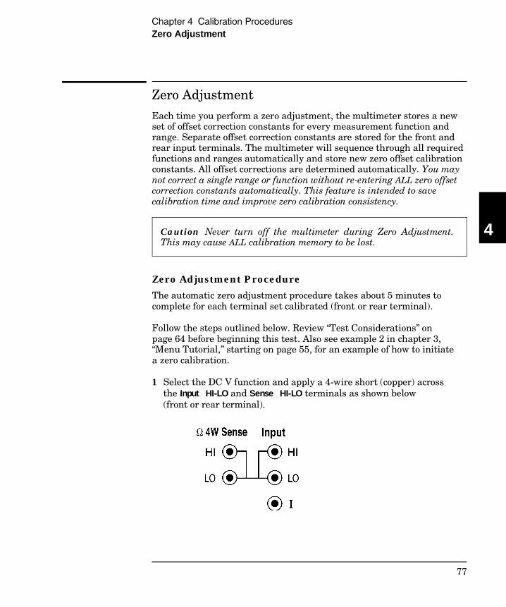
Zero Adjustment
Each time you perform a zero adjustment, the multimeter stores a newset of offset correction constants for every measurement function andrange. Separate offset correction constants are stored for the front andrear input terminals. The multimeter will sequence through all requiredfunctions and ranges automatically and store new zero offset calibrationconstants. All offset corrections are determined automatically. You maynot correct a single range or function without re-entering ALL zero offsetcorrection constants automatically. This feature is intended to savecalibration time and improve zero calibration consistency.
Caution Never turn off the multimeter during Zero Adjustment. This may cause ALL calibration memory to be lost.
Zero Adjustment Procedure The automatic zero adjustment procedure takes about 5 minutes tocomplete for each terminal set calibrated (front or rear terminal).
Follow the steps outlined below. Review “Test Considerations” onpage 64 before beginning this test. Also see example 2 in chapter 3,“Menu Tutorial,” starting on page 55, for an example of how to initiatea zero calibration.
1 Select the DC V function and apply a 4-wire short (copper) acrossthe Input HI-LO and Sense HI-LO terminals as shown below(front or rear terminal).
4
Chapter 4 Calibration ProceduresZero Adjustment
77
Zero Adjustment (continued) 2 Select the shorted terminal set (front or rear terminal) with the
front/rear switch. Separate calibration constants are stored for thefront and rear input terminals.
3 Turn on the menu ( Shift < ) and then use < or > toselect F: CAL MENU.
4 Use ∨ to move down to the “commands” level and select2. CALIBRATE.
5 Use ∨ to move down to the “parameters” level and then set theinput value to 000.0000 mV.
6 Execute the command by pressing Auto/Man .
7 Perform the Zero Offset Verification tests (see page 67) to checkzero calibration results .
8 Repeat steps 1 through 7 for the other input terminal set (front orrear terminal).
ENTER
Chapter 4 Calibration ProceduresZero Adjustment
78
Gain Adjustment
The multimeter stores a single new gain correction constant each timethis procedure is followed. The gain constant is computed from thecalibration value entered for the calibration command and frommeasurements made automatically during the adjustment procedure.
Most measuring functions and ranges have gain adjustment procedures.Only the 100 MΩ range and the ac current, continuity, and diode testfunctions do not have gain calibration procedures. The gain calibrationvalue may be entered through the front panel menu or over the remoteinterface. See example 2 in chapter 3, “Menu Tutorial,” starting onpage 55, for an example of how to enter calibration values.
Adjustments for each function should be performed ONLY in the order shownin the performance verification table. See “Performance Verification Tests”earlier in this chapter for the tables used for gain adjustments.
Gain Adjustment Considerations • The zero adjustment procedure must have been recently performed
prior to beginning any gain adjustment procedures.
• The optional –10 Vdc, 500 Vdc, and 10 mA calibrations should beperformed only after servicing the multimeter’s a-to-d converter orafter replacing network U101 or calibration RAM U505. Refer to the“Optional Gain Calibration Procedures” section starting on page 82for further details.
• When performing a 4-wire ohms gain adjustment, a new gaincorrection constant is also stored for the corresponding 2-wire ohmsmeasurement range. If desired, the 2-wire gain can be adjustedseparately after the 4-wire ohms gain calibration is completed.
• AC voltage gain calibration relies on a previous calibration of the dcvoltage function. Failure to do so can cause significant calibration errors.
Never turn off the multimeter during a Gain Adjustment. This may cause calibration memory for the present function to be lost.
4
Chapter 4 Calibration ProceduresGain Adjustment
79
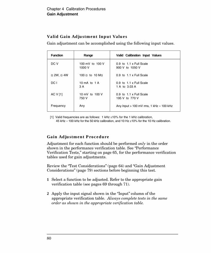
Valid Gain Adjustment Input Values Gain adjustment can be accomplished using the following input values.
Gain Adjustment Procedure Adjustment for each function should be performed only in the ordershown in the performance verification table. See “PerformanceVerification Tests,” starting on page 65, for the performance verificationtables used for gain adjustments.
Review the “Test Considerations” (page 64) and “Gain AdjustmentConsiderations” (page 79) sections before beginning this test.
1 Select a function to be adjusted. Refer to the appropriate gainverification table (see pages 69 through 71).
2 Apply the input signal shown in the “Input” column of theappropriate verification table. Always complete tests in the sameorder as shown in the appropriate verification table.
Function Range Valid Calibration Input Values
DC V
Ω 2W, Ω 4W
DC I
AC V [1]
Frequency
100 mV to 100 V1000 V
100 Ω to 10 MΩ
10 mA to 1 A 3 A
10 mV to 100 V750 V
Any
0.9 to 1.1 x Full Scale 900 V to 1050 V
0.9 to 1.1 x Full Scale
0.9 to 1.1 x Full Scale1 A to 3.03 A
0.9 to 1.1 x Full Scale195 V to 770 V
Any Input > 100 mV rms, 1 kHz – 100 kHz
[1] Valid frequencies are as follows: 1 kHz ±10% for the 1 kHz calibration, 45 kHz – 100 kHz for the 50 kHz calibration, and 10 Hz ±10% for the 10 Hz calibration.
Chapter 4 Calibration ProceduresGain Adjustment
80
3 Turn on the menu ( Shift < ) and then use < or > to select F: CAL MENU.
4 Use ∨ to move down to the “commands” level and select2. CALIBRATE.
5 Use ∨ to move down to the “parameters” level and then set thecalibration value for the present input value.
6 Execute the command by pressing Auto/Man .
7 Perform the appropriate Gain Verification Test to check thecalibration results.
8 Repeat steps 1 through 7 for each gain verification test pointshown in the tables. Each range in the gain adjustment proceduretakes less than 20 seconds to complete.
ENTER
4
Chapter 4 Calibration ProceduresGain Adjustment
81

Optional Gain Calibration Procedures
The optional calibrations in this section are used to enhance theperformance of your Agilent 34401A Multimeter. These calibrations arenormally performed at the factory. These adjustments should beperformed following the repair of your multimeter. You are not requiredto perform these adjustments at any other interval.
–10 Vdc Adjustment Procedure The –10 Vdc calibration electronically corrects the multimeter’s a-to-dconverter linearity characteristic. This adjustment should ONLY beperformed after servicing the a-to-d converter or replacement of thecalibration RAM (U505).
Configuration: DC volts 61⁄2 digit (slow resolution , NPLC 100 – MEAS MENU)
1 Perform the +10 V dc gain adjustment procedure. Note themultimeter’s reading immediately following the +10 V calibration.
2 Manually reverse the multimeter’s input connections and allowtime for thermal offset voltages to settle (usually about 1 minute).
3 Enter the + 10 V reading noted in step 1 above with the “ – ” signfor the –10 V calibration value.
4 Check that the –10 V reversed input is within the following limits:0 ± 30 µV of the +10 V input reading.
Chapter 4 Calibration ProceduresOptional Gain Calibration Procedures
82
500 Vdc Adjustment Procedure The 500 Vdc calibration electronically corrects the multimeter’s 100:1divider network (U101) linearity characteristic for minimum error.This adjustment should be performed only after replacement of thedivider network U101 or the calibration RAM U505.
This calibration procedure is available starting with firmware Revision 3 (REV 03-01-01).
Inputs from 450 V to 550 V are valid for this procedure. A failure tocomplete this procedure correctly will generate error 725, “500V DCcorrection out of range”.
Configuration: DC volts 1000 V range 61⁄2 digit (slow or fast resolution – MEAS MENU)
1 Perform the complete dc Volts gain calibration procedure.
2 Apply +500 Vdc to the input terminals.
3 Enter the CALibration MENU as shown in steps 3 through 6 ofthe “Gain Adjustment Procedure” section on page 80. Enter theexact known value for the +500 Vdc input as shown in step 5.
4 Check that the multimeter reads within the following limits of theapplied input after the calibration has completed: 0 ± 6 mVdc.
4
Chapter 4 Calibration ProceduresOptional Gain Calibration Procedures
83
1/100th Scale AC Adjustment Procedure This calibration procedure is used to enhance the ac volts and ac currentmeasurement accuracy for <1/100th scale inputs. The single calibrationgenerates a correction constant used for all ranges of the ac volts andac current measuring functions. This adjustment should be performedafter servicing ac section circuits or after replacement of the calibrationRAM U505.
This calibration procedure is available starting with firmware Revision 2 (REV 02-01-01).
Inputs from 9 mA to 11 mA are valid for this procedure. A failure tocomplete this procedure correctly will generate error 736, “AC rms 100thscale linearity correction out of range”.
Configuration: AC current 1 A range 61⁄2 digit (slow or fast resolution – MEAS MENU) AC FILTER slow (MEAS MENU)
1 Perform the complete ac volts gain calibration procedure.
2 Apply 10 mA, 1 kHz ac to the current input terminals.
3 Enter the CALibration MENU as shown in steps 3 through 6 ofthe “Gain Adjustment Procedure” section on page 80. Enter theexact known value for the 10 mA ac input as shown in step 5.
4 Check that the multimeter reads within the following limits of theapplied input after the calibration has completed: 0 ± 400 µA ac.
Chapter 4 Calibration ProceduresOptional Gain Calibration Procedures
84
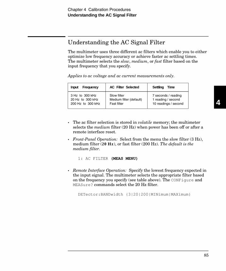
Understanding the AC Signal Filter
The multimeter uses three different ac filters which enable you to eitheroptimize low frequency accuracy or achieve faster ac settling times.The multimeter selects the slow, medium, or fast filter based on theinput frequency that you specify.
Applies to ac voltage and ac current measurements only.
• The ac filter selection is stored in volatile memory; the multimeterselects the medium filter (20 Hz) when power has been off or after aremote interface reset.
• Front-Panel Operation: Select from the menu the slow filter (3 Hz),medium filter (20 Hz), or fast filter (200 Hz). The default is themedium filter.
1: AC FILTER (MEAS MENU)
• Remote Interface Operation: Specify the lowest frequency expected inthe input signal. The multimeter selects the appropriate filter basedon the frequency you specify (see table above). The CONFigure andMEASure? commands select the 20 Hz filter.
DETector:BANDwidth 3|20|200|MINimum|MAXimum
Input Frequency
3 Hz to 300 kHz 20 Hz to 300 kHz 200 Hz to 300 kHz
AC Filter Selected
Slow filter Medium filter (default)Fast filter
Settling Time
7 seconds / reading 1 reading / second 10 readings / second 4
Chapter 4 Calibration ProceduresUnderstanding the AC Signal Filter
85
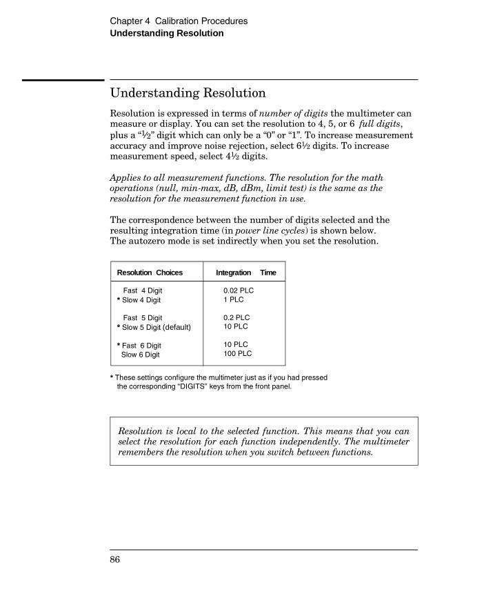
Understanding Resolution
Resolution is expressed in terms of number of digits the multimeter canmeasure or display. You can set the resolution to 4, 5, or 6 full digits,plus a “1⁄2” digit which can only be a “0” or “1”. To increase measurementaccuracy and improve noise rejection, select 61⁄2 digits. To increasemeasurement speed, select 41⁄2 digits.
Applies to all measurement functions. The resolution for the mathoperations (null, min-max, dB, dBm, limit test) is the same as theresolution for the measurement function in use.
The correspondence between the number of digits selected and theresulting integration time (in power line cycles) is shown below.The autozero mode is set indirectly when you set the resolution.
Resolution is local to the selected function. This means that you canselect the resolution for each function independently. The multimeterremembers the resolution when you switch between functions.
Resolution Choices
Fast 4 Digit * Slow 4 Digit
Fast 5 Digit * Slow 5 Digit (default)
* Fast 6 Digit Slow 6 Digit
Integration Time
0.02 PLC 1 PLC
0.2 PLC 10 PLC
10 PLC 100 PLC
* These settings configure the multimeter just as if you had pressed the corresponding “DIGITS” keys from the front panel.
Chapter 4 Calibration ProceduresUnderstanding Resolution
86
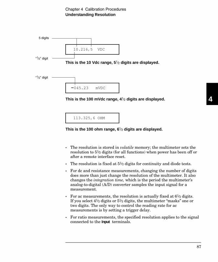
10.216,5 VDC
This is the 10 Vdc range, 51⁄2 digits are displayed.
-045.23 mVDC
This is the 100 mVdc range, 41⁄2 digits are displayed.
113.325,6 OHM
This is the 100 ohm range, 61⁄2 digits are displayed.
• The resolution is stored in volatile memory; the multimeter sets theresolution to 51⁄2 digits (for all functions) when power has been off orafter a remote interface reset.
• The resolution is fixed at 51⁄2 digits for continuity and diode tests.
• For dc and resistance measurements, changing the number of digitsdoes more than just change the resolution of the multimeter. It alsochanges the integration time, which is the period the multimeter’sanalog-to-digital (A/D) converter samples the input signal for ameasurement.
• For ac measurements, the resolution is actually fixed at 61⁄2 digits.If you select 41⁄2 digits or 51⁄2 digits, the multimeter “masks” one ortwo digits. The only way to control the reading rate for acmeasurements is by setting a trigger delay.
• For ratio measurements, the specified resolution applies to the signalconnected to the Input terminals.
“1⁄2” digit
5 digits
“1⁄2” digit
4
Chapter 4 Calibration ProceduresUnderstanding Resolution
87
Resolution (continued)
• Front-Panel Operation: Select either the slow or fast mode for eachresolution setting. The default mode is 5 digits slow.
5: RESOLUTION (MEAS MENU)
See also “To Set the Resolution,” on page 37.
• Remote Interface Operation: You can set the resolution using thefollowing commands.
Specify the resolution in the same units as the measurementfunction, not in number of digits. For example, for dc volts, specify theresolution in volts. For frequency, specify the resolution in hertz.
CONF:VOLT:DC 10,0.001 41⁄2 digits on the 10 Vdc range
MEAS:CURR:AC? 1,1E-6 61⁄2 digits on the 1 A range
CONF:FREQ 1 KHZ,0.1 Hz 1000 Hz input, 0.1 Hz resolution
VOLT:AC:RES 0.05 50 mV resolution on the ac function
CONFigure:<function> <range>|MIN|MAX|DEF,<resolution>|MIN|MAX|DEF
MEASure:<function>? <range>|MIN|MAX|DEF,<resolution>|MIN|MAX|DEF
<function>:RESolution <resolution>|MIN|MAX
Chapter 4 Calibration ProceduresUnderstanding Resolution
88
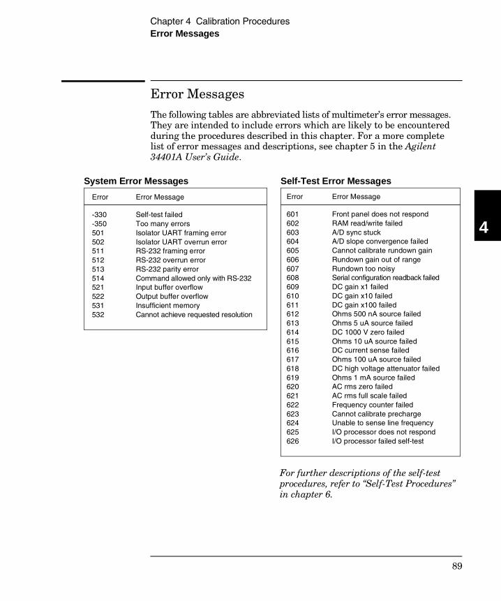
Error Messages
The following tables are abbreviated lists of multimeter’s error messages.They are intended to include errors which are likely to be encounteredduring the procedures described in this chapter. For a more completelist of error messages and descriptions, see chapter 5 in the Agilent34401A User’s Guide.
Error Error Message
-330-350501502511512513514521522531532
Self-test failed Too many errors Isolator UART framing error Isolator UART overrun error RS-232 framing error RS-232 overrun error RS-232 parity error Command allowed only with RS-232Input buffer overflow Output buffer overflow Insufficient memory Cannot achieve requested resolution
System Error Messages
Error Error Message
601602603604605606607608609610611612613614615616617618619620621622623624625626
Front panel does not respond RAM read/write failed A/D sync stuck A/D slope convergence failed Cannot calibrate rundown gain Rundown gain out of range Rundown too noisy Serial configuration readback failedDC gain x1 failed DC gain x10 failed DC gain x100 failed Ohms 500 nA source failed Ohms 5 uA source failed DC 1000 V zero failed Ohms 10 uA source failed DC current sense failed Ohms 100 uA source failed DC high voltage attenuator failed Ohms 1 mA source failed AC rms zero failed AC rms full scale failed Frequency counter failed Cannot calibrate precharge Unable to sense line frequency I/O processor does not respond I/O processor failed self-test
Self-Test Error Messages
For further descriptions of the self-testprocedures, refer to “Self-Test Procedures”in chapter 6.
4
Chapter 4 Calibration ProceduresError Messages
89
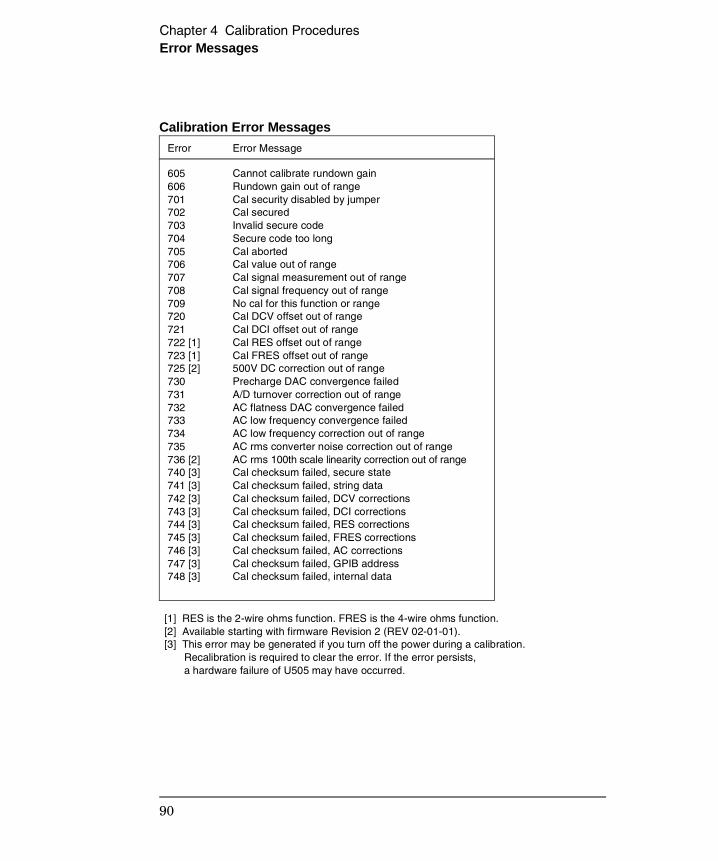
Error Error Message
605606701702703704705706707708709720721722 [1]723 [1]725 [2]730731732733734735736 [2]740 [3]741 [3]742 [3]743 [3]744 [3]745 [3]746 [3]747 [3]748 [3]
Cannot calibrate rundown gain Rundown gain out of range Cal security disabled by jumper Cal secured Invalid secure code Secure code too long Cal aborted Cal value out of range Cal signal measurement out of range Cal signal frequency out of range No cal for this function or range Cal DCV offset out of range Cal DCI offset out of range Cal RES offset out of range Cal FRES offset out of range 500V DC correction out of range Precharge DAC convergence failed A/D turnover correction out of range AC flatness DAC convergence failed AC low frequency convergence failed AC low frequency correction out of range AC rms converter noise correction out of range AC rms 100th scale linearity correction out of rangeCal checksum failed, secure state Cal checksum failed, string data Cal checksum failed, DCV corrections Cal checksum failed, DCI corrections Cal checksum failed, RES corrections Cal checksum failed, FRES corrections Cal checksum failed, AC corrections Cal checksum failed, GPIB address Cal checksum failed, internal data
Calibration Error Messages
[1] RES is the 2-wire ohms function. FRES is the 4-wire ohms function. [2] Available starting with firmware Revision 2 (REV 02-01-01). [3] This error may be generated if you turn off the power during a calibration. Recalibration is required to clear the error. If the error persists, a hardware failure of U505 may have occurred.
Chapter 4 Calibration ProceduresError Messages
90
5
Theory ofOperation
5
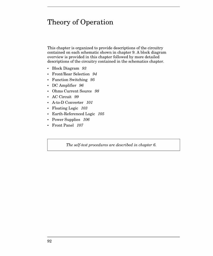
Theory of Operation
This chapter is organized to provide descriptions of the circuitrycontained on each schematic shown in chapter 9. A block diagramoverview is provided in this chapter followed by more detaileddescriptions of the circuitry contained in the schematics chapter.
• Block Diagram 93 • Front/Rear Selection 94• Function Switching 95• DC Amplifier 96• Ohms Current Source 98• AC Circuit 99• A-to-D Converter 101• Floating Logic 103• Earth-Referenced Logic 105• Power Supplies 106• Front Panel 107
The self-test procedures are described in chapter 6.
92

Block Diagram
Referring to the block diagram on page 9-7, you will notice that themultimeter’s circuitry is divided into two major blocks: the floatingcircuitry and the earth (ground) referenced circuitry. All measurement,control, and display functions are contained in the floating section.This section contains the input switching, function selection, andmeasurement circuitry. It also contains the multimeter’s main CPU.
All measurement setup and a-to-d conversion is performed in thefloating section. Each measuring function converts the input to adc voltage between ±12 volts. The ADC (a-to-d conversion) changes thedc voltage into a digital representation. This digital information is usedby the main CPU to calculate the reading. Data stored at the time ofcalibration is recalled and used to correct the measurement data.The corrected reading is then formatted and sent to the front-panelprocessor for display. The corrected reading can also be sent to the earthreferenced I/O processor for output to the remote interface.
The earth referenced circuitry consists of a processor configured as aslave to the main CPU. This processor establishes external I/Ocommunications with the main CPU through an optically-isolated serialcommunication link. The earth referenced processor provides the GPIB(IEEE-488) and RS-232 interfaces. It also handles external trigger andvoltmeter complete handshake signaling.
Separate power supplies are provided for the floating and earthreferenced sections. The front panel operates from the floating sectionwith its logic common different from the floating CPU logic common.
5
Chapter 5 Theory of OperationBlock Diagram
93
Front/Rear Selection
Referring to the front/rear schematic on page 9-8, the purpose of thiscircuitry is to select either the front terminals or the rear terminals(via switch S1). The output of S1 is connected to the Function Switchingschematic (see page 9-9). Input protection circuitry designed to protectthe measuring circuits from high-energy transients such as electrostaticdischarge or power-line transients is also shown.
The double fused (F101, F102) current input is designed to protectagainst potential catastrophic damage caused by accidental inputconnection across high VA sources beyond the 250 V rating of the rear-panel current input fuse. U110 bootstraps out the offset current errorscaused by the leakage current of CR100. CR100 clamps the current inputto protect R120 and R121 from excessive overloads.
Caution Only the front panel or rear panel current input is fused withF101 and F102 as selected by the front/rear switch S1. The unselectedinput is not fused through F101 and F102.
Chapter 5 Theory of OperationFront/Rear Selection
94
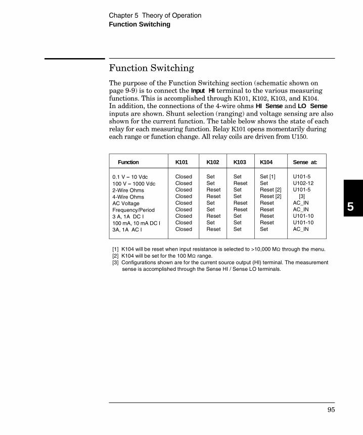
Function Switching
The purpose of the Function Switching section (schematic shown onpage 9-9) is to connect the Input HI terminal to the various measuringfunctions. This is accomplished through K101, K102, K103, and K104.In addition, the connections of the 4-wire ohms HI Sense and LO Senseinputs are shown. Shunt selection (ranging) and voltage sensing are alsoshown for the current function. The table below shows the state of eachrelay for each measuring function. Relay K101 opens momentarily duringeach range or function change. All relay coils are driven from U150.
Function K101 K102 K103 K104 Sense at:
0.1 V – 10 Vdc 100 V – 1000 Vdc 2-Wire Ohms 4-Wire Ohms AC Voltage Frequency/Period 3 A, 1A DC I 100 mA, 10 mA DC I 3A, 1A AC I
ClosedClosedClosedClosedClosedClosedClosedClosedClosed
SetSetResetResetSetSetResetSetReset
SetResetSetSetResetResetSetSetSet
Set [1]SetReset [2]Reset [2]ResetResetResetResetSet
U101-5U102-12U101-5 [3]AC_INAC_INU101-10U101-10AC_IN
[1] K104 will be reset when input resistance is selected to >10,000 MΩ through the menu. [2] K104 will be set for the 100 MΩ range. [3] Configurations shown are for the current source output (HI) terminal. The measurement sense is accomplished through the Sense HI / Sense LO terminals.
5
Chapter 5 Theory of OperationFunction Switching
95
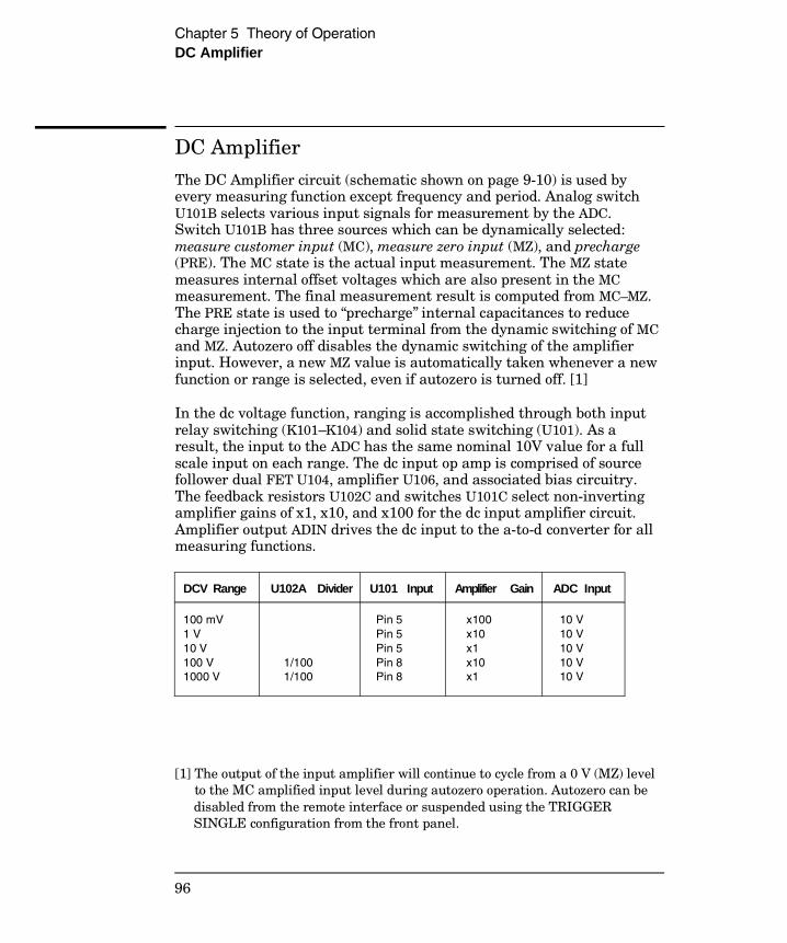
DC Amplifier
The DC Amplifier circuit (schematic shown on page 9-10) is used byevery measuring function except frequency and period. Analog switchU101B selects various input signals for measurement by the ADC.Switch U101B has three sources which can be dynamically selected:measure customer input (MC), measure zero input (MZ), and precharge(PRE). The MC state is the actual input measurement. The MZ statemeasures internal offset voltages which are also present in the MCmeasurement. The final measurement result is computed from MC–MZ.The PRE state is used to “precharge” internal capacitances to reducecharge injection to the input terminal from the dynamic switching of MCand MZ. Autozero off disables the dynamic switching of the amplifierinput. However, a new MZ value is automatically taken whenever a newfunction or range is selected, even if autozero is turned off. [1]
In the dc voltage function, ranging is accomplished through both inputrelay switching (K101–K104) and solid state switching (U101). As aresult, the input to the ADC has the same nominal 10V value for a fullscale input on each range. The dc input op amp is comprised of sourcefollower dual FET U104, amplifier U106, and associated bias circuitry.The feedback resistors U102C and switches U101C select non-invertingamplifier gains of x1, x10, and x100 for the dc input amplifier circuit.Amplifier output ADIN drives the dc input to the a-to-d converter for allmeasuring functions.
[1] The output of the input amplifier will continue to cycle from a 0 V (MZ) level to the MC amplified input level during autozero operation. Autozero can be disabled from the remote interface or suspended using the TRIGGER SINGLE configuration from the front panel.
DCV Range U102A Divider U101 Input Amplifier Gain ADC Input
100 mV 1 V 10 V 100 V 1000 V
1/100 1/100
Pin 5 Pin 5 Pin 5 Pin 8 Pin 8
x100 x10 x1 x10 x1
10 V 10 V 10 V 10 V 10 V
Chapter 5 Theory of OperationDC Amplifier
96

In the DC current function, a current is applied between the Input I andLO terminals. Ranging is accomplished by relay K102 and amplifier gainswitching in U101. Since a known resistor (the shunt resister) is connectedbetween these terminals, a voltage proportional to the unknown currentis generated. The voltage sensed at R121 is measured by the multimeter’sdc circuitry. The table below illustrates the dc current measuringfunction configurations.
Resistance measurements are made by applying a known currentthrough an unknown resistance. The resulting voltage drop across theunknown resistance is then measured by the multimeter’s dc circuitry.The 100 MΩ range is measured using the known internal 10 MΩresistance (U102A) in parallel with the unknown input resistance whileapplying the 500 nA current source. The result is computed from themeasured data. The internal 10 MΩ resistance is determined whenevera zero calibration is performed.
In the 2-wire ohms function, the voltage drop is measured across theInput HI and Input LO terminals. In the 4-wire ohms function, the voltageis measured across the HI Sense and LO Sense terminals. Lead resistancesin series with the current source (Input HI–LO) are not part of the finalmeasurement. However, they do reduce the available current sourcecompliance voltage for the resistor under test. The ohms current sourcewill become non-linear when the compliance voltage limit is exceeded.The full scale voltage developed across the unknown resistor and thedc amplifier gain for each resistance range are tabulated below.
DCI Range Shunt Resistor U101–10 Input Amplifier Gain ADC Input
3A 1A 100 mA 10 mA
0.1Ω 0.1Ω 5.1Ω 5.1Ω
300 mV 100 mV 510 mV 51 mV
x10 x100 x10 x100
3V 10V 5.1V 5.1V
Ohms Range Voltage Across R Amplifier Gain ADC Input
100 Ω1 kΩ to 100 kΩ 1 MΩ10 MΩ100 MΩ
100 mV 1 V 5 V 5 V 4.5 V
x100 x10 x1 x1 x1
10 V 10 V 5 V 5 V 4.5 V
5
Chapter 5 Theory of OperationDC Amplifier
97

Ohms Current Source
The ohms current source (schematic shown on page 9-10) flows from theInput HI terminal to the Input LO terminal for both the 2-wire and 4-wireohms functions. Each current value is generated by forcing a stable,precise voltage across a stable resistance. The value of the currentbecomes part of the range gain constant stored during calibration.
The +7 V reference voltage is used to generate a stable reference currentwith U201A. R201 and R202 are the resistance references for the currentsources as shown in the table below. The IREF current is used toproduce a precise voltage drop across the 28.57 kΩ resistor in U102D-4.The IREF generated using R202 produces an approximate 5 V dropacross the 28.57 kΩ resistor. The IREF generated using R201 producesan approximate 0.5 V drop. This voltage is used to force a referencevoltage across the selected current source range resistor (5 kΩ, 50 kΩ,500 kΩ, 1 MΩ) by U201B. The resulting precision current flows throughJFET Q202 and protection circuit Q203 to Q211, and CR202 to relay K102where it is switched to the Input HI terminal for ohms measurements.
The protection circuits are designed to protect the ohms current sourcefrom inadvertently applied voltages in excess of ±1000 V. Protectionfrom large positive voltages is provided by the reverse breakdownvoltage of CR202. Protection from large negative voltages is provided bythe sum of the collector to base breakdown voltages of Q203, Q205, Q207,and Q209. Bias for these transistors is provided by Q211 and R203 toR206 while negative overvoltages are applied.
Ohms Range CurrentOpen Circuit Voltage
Compliance Limit Reference
Isource R U102D
100 Ω1 kΩ10 kΩ100 kΩ1 MΩ10 MΩ100 MΩ [1]
1 mA 1 mA 100 µA 10 µA 5 µA 500 nA 500 nA [1]
9 V 9 V 9 V 9 V 9 V 14 V 5 V
2.5 V 2.5 V 4 V 4 V 8 V 10 V
R202 R202 R202 R202 R202 R201 R201
5 kΩ 5 kΩ 50 kΩ 500 kΩ 1 MΩ 1 MΩ 1 MΩ
[1] Measured in parallel with the internal 10 MΩ resistor.
Chapter 5 Theory of OperationOhms Current Source
98
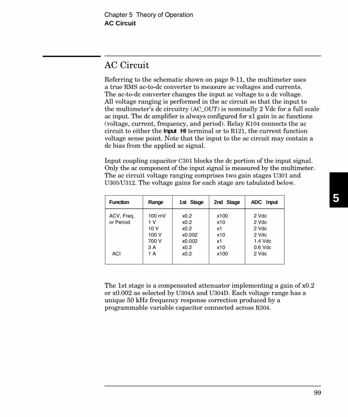
AC Circuit
Referring to the schematic shown on page 9-11, the multimeter usesa true RMS ac-to-dc converter to measure ac voltages and currents.The ac-to-dc converter changes the input ac voltage to a dc voltage.All voltage ranging is performed in the ac circuit so that the input tothe multimeter’s dc circuitry (AC_OUT) is nominally 2 Vdc for a full scaleac input. The dc amplifier is always configured for x1 gain in ac functions(voltage, current, frequency, and period). Relay K104 connects the accircuit to either the Input HI terminal or to R121, the current functionvoltage sense point. Note that the input to the ac circuit may contain adc bias from the applied ac signal.
Input coupling capacitor C301 blocks the dc portion of the input signal.Only the ac component of the input signal is measured by the multimeter.The ac circuit voltage ranging comprises two gain stages U301 andU305/U312. The voltage gains for each stage are tabulated below.
The 1st stage is a compensated attenuator implementing a gain of x0.2or x0.002 as selected by U304A and U304D. Each voltage range has aunique 50 kHz frequency response correction produced by aprogrammable variable capacitor connected across R304.
Function Range 1st Stage 2nd Stage ADC Input
ACV, Freq, or Period
ACI
100 mV 1 V10 V100 V700 V3 A1 A
x0.2 x0.2 x0.2 x0.002 x0.002 x0.2 x0.2
x100 x10 x1 x10 x1 x10 x100
2 Vdc 2 Vdc 2 Vdc 2 Vdc 1.4 Vdc 0.6 Vdc 2 Vdc
5
Chapter 5 Theory of OperationAC Circuit
99
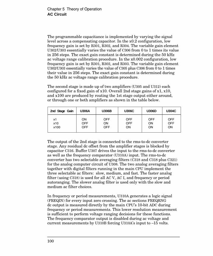
The programmable capacitance is implemented by varying the signallevel across a compensating capacitor. In the x0.2 configuration, lowfrequency gain is set by R301, R302, and R304. The variable gain elementU302/U303 essentially varies the value of C306 from 0 to 1 times its valuein 256 steps. The exact gain constant is determined during the 50 kHzac voltage range calibration procedure. In the x0.002 configuration, lowfrequency gain is set by R301, R302, and R303. The variable gain elementU302/U303 essentially varies the value of C305 plus C306 from 0 to 1 timestheir value in 256 steps. The exact gain constant is determined duringthe 50 kHz ac voltage range calibration procedure.
The second stage is made up of two amplifiers (U305 and U312) eachconfigured for a fixed gain of x10. Overall 2nd stage gains of x1, x10,and x100 are produced by routing the 1st stage output either around,or through one or both amplifiers as shown in the table below.
The output of the 2nd stage is connected to the rms-to-dc converterstage. Any residual dc offset from the amplifier stages is blocked bycapacitor C316. Buffer U307 drives the input to the rms-to-dc converteras well as the frequency comparator (U310A) input. The rms-to-dcconverter has two selectable averaging filters (C318 and C318 plus C321)for the analog computer circuit of U308. The two analog averaging filterstogether with digital filters running in the main CPU implement thethree selectable ac filters: slow, medium, and fast. The faster analogfilter (using C318) is used for all AC V, AC I, and frequency or periodautoranging. The slower analog filter is used only with the slow andmedium ac filter choices.
In frequency or period measurements, U310A generates a logic signal(FREQIN) for every input zero crossing. The ac sections FREQRNGdc output is measured directly by the main CPU’s 10-bit ADC duringfrequency or period measurements. This lower resolution measurementis sufficient to perform voltage ranging decisions for these functions.The frequency comparator output is disabled during ac voltage andcurrent measurements by U310B forcing U310A’s input to –15 volts.
2nd Stage Gain U306A U306B U306C U306D U304C
x1 x10 x100
ON OFF OFF
OFF ON OFF
OFF OFF ON
OFF ON ON
OFF OFF ON
Chapter 5 Theory of OperationAC Circuit
100
A-to-D Converter
The analog-to-digital converter (ADC) is used to change dc voltages intodigital information (schematic shown on page 9-12). The circuitryconsists of an integrator amplifier (U402 and U420), current steeringswitch U411, resistor network U102E, voltage reference U403, ADCcontroller U501, and residue ADC U500.
The ADC method used by the 34401A is called multislope III. It is basedon patented Agilent ADC technology. Multislope III is a chargebalancing continuously integrating analog-to-digital converter. The ADCcharge balancing algorithm is always running, even when themultimeter is not triggered. The input voltage continuously forcescharge onto the integrator capacitors C400 and C401 through U102E–R16.
Switches U411A and U411B steer fixed positive or negative referencecurrents onto the integrator capacitor to cancel, or balance, theaccumulated input charge. The level shifted (R403 and R406) output ofthe integrator is checked every 2.66 µs by the U501 COMP input. Logicstate machines in U501 control the U411 current steering to continuouslyseek an approximate 2.5 V level on the integrator amplifier output,FLASH. If the ADC input voltage ADIN is between ±15 V, the integratoroutput (FLASH) will remain within the 0 V to 5 V range of the U500 onchip ADC. An input greater than +15 V may cause the integrator output(U402–6) to saturate at about –18 V. An input less than –15 V may causeU402 to saturate with an output of about +18 V. The U500 ADC input(FLASH) is clamped to 0 V or 5 V by R405 and CR403 to protect U500.
The integrator amplifier is formed by U402 and U420. Resistors R420 andR421 affect the amplifier stability. Amplifier oscillation may occur iftheir values are incorrect. Amplifier U420 improves the offset voltagecharacteristics of integrator amplifier U402.
5
Chapter 5 Theory of OperationA-to-D Converter
101
Each analog-to-digital conversion begins when the multimeter istriggered. The ADC starts by clearing the integrator slope count in U501.At the end of the integration period, the slope count is latched.The slope count provides the most significant bits of the input voltageconversion. The least significant bits are converted by the on chip ADCof CPU U500.
The instrument precision voltage reference is U403. Resistor R409provides a stable bias current for the reference zener diode. R408 andCR404 provide a bias to assure that the reference zener biases to +7 Vduring power up. IC U400A amplifies the voltage reference to +10 Vwhile amplifier U401A inverts the +10 V reference to –10 V. The referencevoltages force precision slope currents for the integrating ADC throughU102E–R17, R18. Amplifier U401B provides a precise +5 V reference forthe U500 on chip ADC.
Chapter 5 Theory of OperationA-to-D Converter
102
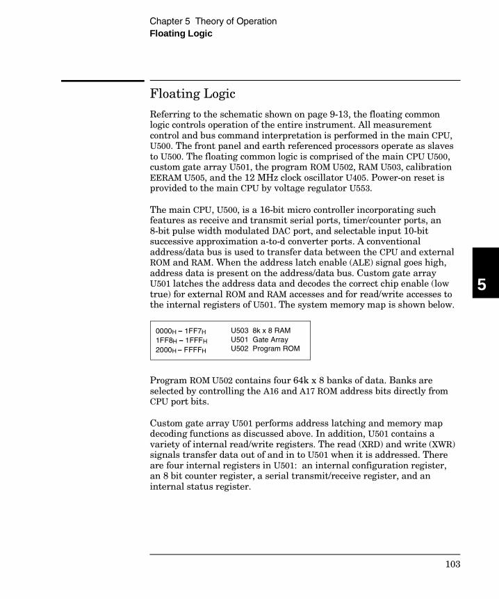
Floating Logic
Referring to the schematic shown on page 9-13, the floating commonlogic controls operation of the entire instrument. All measurementcontrol and bus command interpretation is performed in the main CPU,U500. The front panel and earth referenced processors operate as slavesto U500. The floating common logic is comprised of the main CPU U500,custom gate array U501, the program ROM U502, RAM U503, calibrationEERAM U505, and the 12 MHz clock oscillator U405. Power-on reset isprovided to the main CPU by voltage regulator U553.
The main CPU, U500, is a 16-bit micro controller incorporating suchfeatures as receive and transmit serial ports, timer/counter ports, an8-bit pulse width modulated DAC port, and selectable input 10-bitsuccessive approximation a-to-d converter ports. A conventionaladdress/data bus is used to transfer data between the CPU and externalROM and RAM. When the address latch enable (ALE) signal goes high,address data is present on the address/data bus. Custom gate arrayU501 latches the address data and decodes the correct chip enable (lowtrue) for external ROM and RAM accesses and for read/write accesses tothe internal registers of U501. The system memory map is shown below.
Program ROM U502 contains four 64k x 8 banks of data. Banks areselected by controlling the A16 and A17 ROM address bits directly fromCPU port bits.
Custom gate array U501 performs address latching and memory mapdecoding functions as discussed above. In addition, U501 contains avariety of internal read/write registers. The read (XRD) and write (XWR)signals transfer data out of and in to U501 when it is addressed. Thereare four internal registers in U501: an internal configuration register,an 8 bit counter register, a serial transmit/receive register, and aninternal status register.
0000H – 1FF7H 1FF8H – 1FFFH 2000H – FFFFH
U503 8k x 8 RAM U501 Gate Array U502 Program ROM
5
Chapter 5 Theory of OperationFloating Logic
103

The counter register is used to capture either ADC slope count at theCOMP input or frequency count at the FREQIN input. The COMP inputfunctions as both a clocked comparator and the slope counter input forthe ADC. In both cases the counter register captures the lower 8 bits of a24-bit counter. The upper 16 bits of the count are captured by the SYNCinput to U500. The serial register is used to send and receive serial databytes from the main CPU to the 40 bit (5 x 8 bits) measurementconfiguration register comprised of U309, U311, U150, and U101 or tocommunicate with the front panel processor. The serial register ismultiplexed to these two circuits. The transmission rate is selected to 1.5 M bits/second for the measurement configuration registers and to 93.75 k bits/second for communication with the front panel processor.The general serial interface is a 3-bit interface as shown below.
Serial data is received simultaneously as serial data is clocked out.The measurement configuration readback data (SERRBK) is onlychecked during self-test operation. Front panel data is exchanged inboth directions whenever a byte is sent from U501. The measurementconfiguration register data is strobed to outputs by U500 signal SERSTB.Interrupts from the front panel are detected by U501 and signaled to theprocessor by CHINT. The processor line FPINT signals the front panelprocessor that U501 has data to send.
The gate array (U501) internal status register reports a serial port busybit and 4 bits of time interpolation data. The time interpolation data isused to extend the time counting resolution of processor U500 duringADC conversions and frequency measurements.
The multimeter’s calibration correction data are stored in a 128 x 16 bitnon-volatile electrically erasable RAM, EERAM U505. The EERAMread/write data is accessed by a 4-bit serial protocol controlled by U500.
U501 Internal Signal Measurement Configuration Signals Front Panel Signals
Serial Clock Data OUT (send) Data IN (receive)
SERCK SERDAT0 SERRBK
XFPSK FPDI FPDO
Chapter 5 Theory of OperationFloating Logic
104

The main processor has an on chip 10-bit successive approximation ADCwith two selectable inputs: FLASH and FREQRNG. The FLASH input isused to sample the residual charge on the main integrating ADC outputof U402. The FREQRNG input is used to make voltage ranging decisionsconcurrent with frequency or period measurements.
The main CPU’s pulse width modulated DAC outputs a 0 V to 5 V dclevel after filtering the 23 kHz output with R507 and C512. This level isused to adjust the precharge amplifier offset voltage in U101. Port bitsare also configured to detect the front/rear input switch position (FXR0)and to measure the input power line frequency (LSENSE). Frequenciesfrom 55 Hz to 66 Hz are measured as 60 Hz. All other input frequenciesare assumed to be 50 Hz.
The main CPU communicates with the earth referenced processor U700through an optically isolated (U506 and U704) asynchronous serial link.Data is sent in an 11-bit frame at a rate of 187.5 k bits/second. When theRS-232 interface is selected, data is sent across the isolated link at 93.75 k bits/second. The 11-bit data frame is configured for one start bit,eight data bits, one control bit, and one stop bit.
Earth-Referenced Logic
The earth referenced logic circuits (schematic shown on page 9-14)provide all rear panel input/output capability. Microprocessor U700handles GPIB (IEEE-488) control through bus interface chip U701 andbus receiver/driver chips U702 and U703. The RS-232 interface is alsocontrolled through U700. RS-232 transceiver chip U706 provides therequired level shifting to approximate ±9 volt logic levels throughon-chip charge-pump power supplies using capacitors C708 and C709.Communication between the earth referenced logic interface circuitsand the floating measurement logic is accomplished through anoptically-isolated bi-directional serial interface. Isolator U506 couplesdata from U700 to microprocessor U501. Isolator U704 couples data fromU501 to microprocessor U700.
5
Chapter 5 Theory of OperationEarth-Referenced Logic
105
Power Supplies
Referring to the schematic shown on page 9-15, the multimeter uses twotypes of power supplies: floating supplies and earth referenced supplies.The floating supply outputs are ±18 Vdc, +5 Vdc, and a 5 Vrms centertapped filament supply for the vacuum fluorescent display. The earthreferenced circuits are powered from a single +5 Vdc supply.
The ac mains are connected by module P1. This module includes thefunctions of mains connection, on/off switching, and line voltageselection (100/120/220/240). The multimeter automatically configuresfor the applied line frequency by counting the frequency of the output ofclamp circuit CR554, R555, C555 (LSENSE).
The 5 volt floating supply is produced by bridge rectifier CR552, filtercapacitor C556, and regulator U553. The reset output of U553 will changeto logic LO when the unregulated dc input to the regulator falls below5.5 volts. XPONRST is the instrument master hardware reset signal.This supply powers all floating logic. Relay drive circuits are alsopowered from this supply.
The floating ±18 volt supplies are produced by bridge rectifier CR551,filter capacitors C551 and C553, and regulators U551 and U552. Thesesupplies are used to power all measuring circuits. In addition, thevacuum fluorescent display is driven from the ±18 volt supplies. Aseparate winding of T1 provides a center tapped 5 Vrms filament supplyfor the display. Bias circuit CR556, R556, and C559 generates therequired cathode dc bias for the display filament supply.
The 5 volt earth referenced supply is produced by rectifier CR751, C752,and regulator U751. This supply is earth referenced by the screw whichmounts the PC board to the instrument chassis. The GPIB (IEEE-488)and RS-232 interfaces along with other input/output circuits are poweredfrom this supply.
Chapter 5 Theory of OperationPower Supplies
106
Front Panel
The front panel circuits (schematic shown on page 9-16) consist ofvacuum fluorescent display control, display high voltage drivers, andkeyboard scanning. Communication between the front panel andfloating logic circuits is accomplished through a 4-wire bidirectionalserial interface. The main CPU, U500, can cause a hardware reset toprocessor U600 by signal IGFPRES. The front panel logic operates from+13 volts (logic 0) and +18 volts (logic 1). The four serial communicationsignals are level shifted by comparator U602 from the floating logic 0 Vto 5 V levels to the 13 V to 18 V levels present on the front panelassembly. The front panel logic low supply (+13 volts) is produced by the+18 volt supply and 4.7 V zener CR606. Level shift outputs for the frontpanel receive data are clamped to the 13 volt supply VLB.
Display anode and grid voltages are +18 volts for an “on” segment and–18 volts for an “off” segment. The –12 V cathode bias for the display is provided by filament winding center tap bias circuit CR556, R556, andC559 on the power supply schematic (see page 9-15). Keyboard scanningis accomplished through a conventional scanned row-column key matrix.Keys are scanned by outputing data to shift register U601 to poll eachkey column for a key press. Row read-back data are parallel loaded intoshift register U601 and shifted back into processor U600 for decoding andcommunication to the floating logic circuits.
5
Chapter 5 Theory of OperationFront Panel
107

108
6
Service
6
Service
This chapter discusses the procedures involved for returning a failedmultimeter to Agilent for service or repair. Subjects covered include thefollowing:
• Operating Checklist 111• Types of Service Available 112• Repackaging for Shipment 113• Electrostatic Discharge (ESD) Precautions 114• Surface Mount Repair 114• To Replace the Power-Line Fuse 114• To Replace the Current Input Fuses 115• To Connect the Pass/Fail Output Signals 115• Troubleshooting Hints 117• Self-Test Procedures 120
110
Operating Checklist
Before returning your multimeter to Agilent for service or repair, checkthe following items:
Is the multimeter inoperative?
Verify that the ac power cord is connected to the multimeter.Verify that the front-panel Power switch is depressed.
Verify that the power-line fuse is good. Verify the power-line voltage setting.
See “To Prepare the Multimeter for Use” on page 29.
Does the multimeter fail self-test?
Verify that the correct power-line voltage is selected.
See “To Prepare the Multimeter for Use” on page 29.
Remove all measurement connections to the multimeter. Ensure that all measurement terminal connections (both front and rear terminals) are removed while the self-test is performed. Errors may be induced by ac signals present on the multimeter input terminals during self-test. Long test leads can act as an antenna causing pick-up of ac signals.
Is the multimeter’s current input inoperative?
Verify that the rear panel 3 A, 250 V current fuse is functional.Verify that the internal 7 A, 250 V high-interrupt fuse is functional.
See “To Replace the Current Input Fuses” on page 115.
6
Chapter 6 ServiceOperating Checklist
111
Types of Service Available
If your multimeter fails within one year of original purchase, Agilentwill repair or replace it free of charge. If your unit fails after the oneyear warranty expires, Agilent will repair or replace it at a verycompetitive price. Agilent will make the decision locally whether torepair or replace your unit.
Standard Repair Service (Worldwide) Contact your nearest Agilent Service Center. They will arrange to haveyour multimeter repaired or replaced.
Agilent Express Service (U.S. only) You can receive a replacement 34401A via overnight shipment for shortdowntime.
1 Call 1-877-444-7278 and ask for “Agilent Express.”
• You will be asked for your shipping address and a credit card numberto guarantee return of your failed multimeter.
• If you do not return your failed multimeter within 45 days, yourcredit card will be billed for a new 34401A.
• If you choose not to supply a credit card number, you will be asked tosend your failed unit to a designated Agilent Service Center. Afterthe failed unit is received, Agilent will send your replacement unit.
2 Agilent will immediately send a replacement 34401A to you viaovernight shipment.
• The replacement unit will have a different serial number than yourfailed unit.
• If you can not accept a new serial number for the replacement unit,use the Standard Repair Service option described above.
Chapter 6 ServiceTypes of Service Available
112
• If your failed unit was “in-warranty,” your replacement unit willcontinue the warranty time clock to the end of your one year standardwarranty. You will not be billed for the replacement unit as long asthe failed unit is received by Agilent.
• If your one year warranty has expired, Agilent will bill you for the34401A exchange price — less than a new unit price. Agilent warrants exchange units against defects for 90 days.
Repackaging for Shipment
For the Agilent Express Service described on the previous page, returnyour failed 34401A to the designated Agilent Service Center using theshipping carton of the exchange unit. A shipping label will be supplied.Agilent will notify you when your failed unit has been received.
If the instrument is to be shipped to Agilent for service or repair, besure to:
• Attach a tag to the multimeter identifying the owner and indicatingthe required service or repair. Include the instrument model numberand full serial number.
• Place the multimeter in its original container with appropriatepackaging material.
• Secure the container with strong tape or metal bands.
If the original shipping container is not available, place your unit in acontainer which will ensure at least 4 inches of compressible packagingmaterial around all sides for the multimeter. Use static-free packagingmaterials to avoid additional damage to your unit.
Agilent recommends that you always insure shipments.
6
Chapter 6 ServiceRepackaging for Shipment
113
Electrostatic Discharge (ESD) Precautions
Almost all electrical components can be damaged by electrostaticdischarge (ESD) during handling. Component damage can occur at electrostatic discharge voltages as low as 50 volts.
The following guidelines will help prevent ESD damage when servicingthe multimeter or any electronic device.
• Disassemble instruments only in a static-free work area.
• Use a conductive work area to dissipate static charge.
• Use a conductive wrist strap to dissipate static charge accumulation.
• Minimize handling.
• Keep replacement parts in original static-free packaging.
• Remove all plastic, styrofoam, vinyl, paper, and otherstatic-generating materials from the immediate work area.
• Use only anti-static solder suckers.
Surface Mount Repair
Surface mount components should only be removed using solderingirons or desoldering stations expressly designed for surface mountcomponents. Use of conventional solder removal equipment will almostalways result in permanent damage to the printed circuit board and willvoid your Agilent factory warranty.
To Replace the Power-Line Fuse
The power-line fuse is located within the multimeter’s fuse-holderassembly on the rear panel (see page 31). Refer to the rear panel for theproper fuse rating. The 250 mAT slow-blow fuse has Agilent partnumber 2110-0817 and is used for all line voltages.
Chapter 6 ServiceElectrostatic Discharge (ESD) Precautions
114
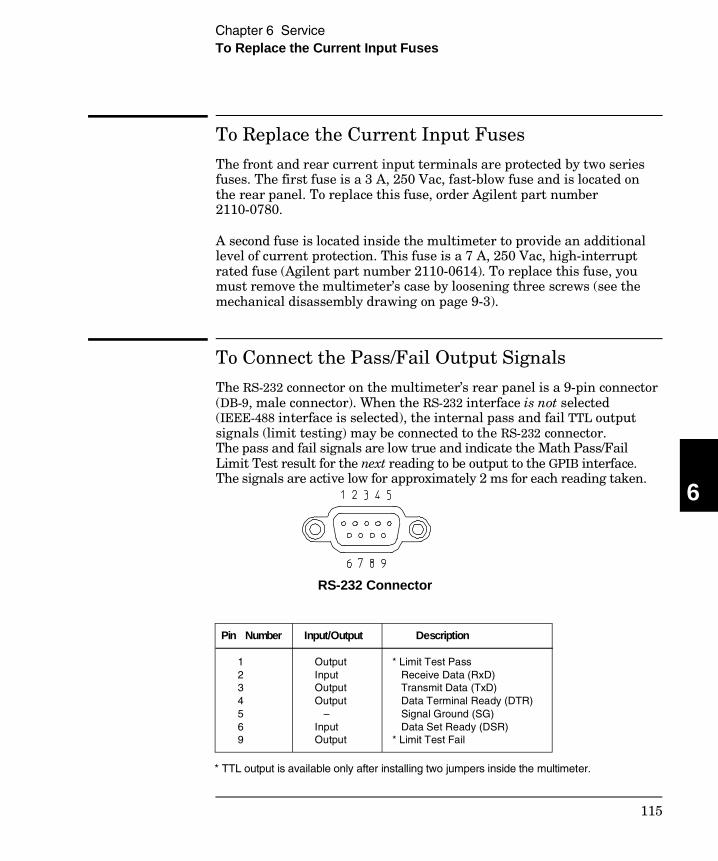
To Replace the Current Input Fuses
The front and rear current input terminals are protected by two seriesfuses. The first fuse is a 3 A, 250 Vac, fast-blow fuse and is located onthe rear panel. To replace this fuse, order Agilent part number2110-0780.
A second fuse is located inside the multimeter to provide an additionallevel of current protection. This fuse is a 7 A, 250 Vac, high-interruptrated fuse (Agilent part number 2110-0614). To replace this fuse, youmust remove the multimeter’s case by loosening three screws (see themechanical disassembly drawing on page 9-3).
To Connect the Pass/Fail Output Signals
The RS-232 connector on the multimeter’s rear panel is a 9-pin connector(DB-9, male connector). When the RS-232 interface is not selected(IEEE-488 interface is selected), the internal pass and fail TTL outputsignals (limit testing) may be connected to the RS-232 connector.The pass and fail signals are low true and indicate the Math Pass/FailLimit Test result for the next reading to be output to the GPIB interface.The signals are active low for approximately 2 ms for each reading taken.
Pin Number
1 2 3 4 5 6 9
Input/Output Output Input Output Output – Input Output
Description
* Limit Test Pass Receive Data (RxD) Transmit Data (TxD) Data Terminal Ready (DTR) Signal Ground (SG) Data Set Ready (DSR) * Limit Test Fail
* TTL output is available only after installing two jumpers inside the multimeter.
RS-232 Connector
6
Chapter 6 ServiceTo Replace the Current Input Fuses
115
Pass/Fail Output (continued) Installation Procedure
The assembly drawings and schematics are located in chapter 9,“Schematics.”
1 Unscrew the two rear bezel captive screws (see the mechanicaldisassembly drawing on page 9-3).
2 Remove one screw from bottom cover (see the mechanicaldisassembly drawing on page 9-3).
3 Slide the metal cover off of the chassis (see the mechanicaldisassembly drawing on page 9-3).
4 Install JM710 and JM711 located adjacent to the power supply connector, P751. A bare wire may be used if a 0 ohm surfacemount resistor is not available. (See the component locatordiagram for the 34401-66501 Main PC Board on page 9-5.)
5 Reassemble the multimeter. Make sure to reinstall the bottomcover screw.
Do not use the RS-232 interface if you have configured the multimeterto output pass/fail signals on pins 1 and 9. Internal components on theinterface circuitry may be damaged.
Chapter 6 ServiceTo Connect the Pass/Fail Output Signals
116
Troubleshooting Hints
This section provides a brief check list of common failures. Beforetroubleshooting or repairing the multimeter, make sure the failure is inthe instrument rather than any external connections. Also make surethat the instrument is accurately calibrated. The multimeter’s circuitsallow troubleshooting and repair with basic equipment such as a61⁄2-digit multimeter and a 100 MHz oscilloscope.
Caution This instrument contains CMOS integrated circuits whichare susceptible to failure due to electrostatic discharge. Refer to the“Electrostatic Discharge (ESD) Precautions” section earlier in thischapter for further handling precautions.
Unit is inoperative Verify that the ac power cord is connected to the multimeter.
Verify that the front-panel Power switch is depressed. Verify that the power-line fuse is good.
Verify the power-line voltage setting.
See “To Prepare the Multimeter for Use” on page 29.
Unit reports an error between 740 and 748 These errors may be produced if you accidentally turn off power to theunit during a calibration or while changing a non-volatile state of theinstrument. Recalibration or resetting the state should clear the error.If the error persists, a hardware failure of U505 may have occurred.
Unit fails self-test Verify that the correct power-line voltage setting is selected. Also,ensure that all measurement terminal connections (both front paneland rear terminals) are removed while the self-test is performed. Errorsmay be induced by ac signals present on the multimeter input terminalsduring self-test. Long test leads can act as an antenna causing pick-upof ac signals.
6
Chapter 6 ServiceTroubleshooting Hints
117
Troubleshooting Hints(continued)
Current input is inoperative
Verify that the rear panel 3 A, 250 V current fuse is functional.Verify that the internal 7 A, 250 V high-interrupt fuse is functional.
Power supply problems Check that the input to the supply voltage regulator is at least 1 Vgreater than its output. Circuit failures can cause heavy supply loadswhich may pull down the regulator output voltage.
Some circuits produce their own local power supplies from the mainsupplies. Be sure to check that these local supplies are active.In particular, the ADC (analog-to-digital converter), ac, and front panelsections have local supplies. Always check that the power supplies arefree of ac oscillations using an oscilloscope.
Failure of the analog voltage reference U403 will cause many self-testfailures. Be certain that U403 is seated properly in its socket.
Check the main supply voltages as shown below.
Readings indicate OVERLOADAn overload is caused when the gain and offset corrected reading resultis greater than the full scale value (or less than the full scale value) forthe present measuring function and range. This can be caused byincorrect calibration, saturated (railed) dc input amplifier, or by failureof the a-to-d converter. Overload can also be caused if the current sourcevalue is too large in the ohms function. In ac functions, overload willalso be generated if the output of the rms-to-dc converter U308 is greaterthan 2 Vdc for sinewave inputs > 20 Hz.
Power Supply Minimum Maximum
+5 Ground Ref. +5 Floating +18 Floating -18 Floating +7REF Floating +5REF Floating
4.75 V 4.75 V 18.0 V -17.0 V 6.45 V 4.75 V
5.25 V 5.25 V 20.0 V -19.1 V 7.35 V 5.25 V
Chapter 6 ServiceTroubleshooting Hints
118
Readings are inaccurateInaccurate readings are normally caused by either invalid calibration orby non-linear measuring circuits. If recalibration does not correct theinaccuracies, the amplifier or solid state switches may be causingmeasurement non-linearities. Non-linear operation of the ohms currentsource due to failure of Q202 to Q211 may cause reading inaccuracies inthe ohms function. If the input to the ADC is shown to be linear, checkthe ±10 V reference voltages. Check switch U411, U420, and U402 forproper operation.
Readings show excessive noise
Reading noise is usually caused by the dc input amplifier or the a-to-dconverter circuitry. Remember that it is normal for the most sensitivemeasuring ranges to show more noise than the least sensitive ranges.Verify that the multimeter fails to meet its zero input specifications.Low frequency ac measurements will experience more noise than higherfrequency inputs. Verify that the multimeter fails to meet ac specifications.Ensure that the correct ac filter is selected for the applied input signalfrequency.
If calibration constants become corrupted, it is possible for themultimeter to generate noisy results without a hardware failure.Perform a new zero offset calibration and gain calibration beforeattempting to service the instrument.
Readings indicate zero with any input applied
A constant zero reading is normally caused when either the output ofthe dc input amplifier is stuck at a fixed level (like 0 volts) or when thea-to-d converter integrator amplifier U402 is stuck at a fixed level.
6
Chapter 6 ServiceTroubleshooting Hints
119
Self-Test Procedures
Power-On Self-Test Each time the multimeter is powered on, a small set of self-tests areperformed. These tests check that the minimum set of logic andmeasurement hardware are functioning properly. The power-onself-tests are listed below in the order they are executed. For a morecomplete description of each test, see the description in the followingsection, “Self-Test Descriptions” (see below).
• Test 701, checks that the calibration security disable jumper is removed.
• Self-test 624, determines the correct power-line frequency for themeasurement section.
• Copy secured calibration constants from calibration ram U505 to working ram U503. Errors 740 through 748 may be reported during this operation.
• Self-test 625, establishes communication with the I/O processor U700.
• Self-test 601, establishes communication with the front panel U600.
• Self-test 603, checks that the ADC logic is functioning U501.
• Self-test 604, checks that the ADC analog hardware is functioning.
• Self-test 626, checks that U700 passed its self-test.
Self-Test Descriptions
This section provides a brief description for each internal self-testprocedure including purpose, test setup, and failure criteria. Erroneousself-test failures may occur when the power line voltage is improperlyset. Errors may also be produced by ac signals present on themultimeter input terminals (front or rear) during self-test. Long testleads can act as an antenna causing pick-up of ac signals.
Failing a self-test procedure indicates that parts of the multimeter arenot functioning properly and need to be serviced. Passing self-test givesa better than 90% confidence that the Agilent 34401A hardware isoperational. However, passing self-test does not guarantee that themultimeter will produce accurate results. Only performance verificationcan ensure the accuracy of measurement results.
Chapter 6 ServiceSelf-Test Procedures
120
Self-test procedures are numbered in the order in which they areexecuted. The order is designed to build confidence from a small kerneltowards progressively more complex internal configurations.
Many individual self-test procedures may be executed from the frontpanel by selecting the desired test number from the parameter list ofthe TEST command (in the SYS MENU).
Note K101 is always open during self-test so that signals present on theinput terminals are disconnected. However, ac signals may still feedthrough K101 causing self-test failures as mentioned earlier in this section.
601 Front panel does not respond The main CPU U500 attempts toestablish serial communications with the front panel processor U600.During this test, U600 turns on all display segments. Communicationmust function in both directions for this test to pass.
602 RAM read/write failed This test writes and reads a 55H and AAHchecker board pattern to each address of ram U503. Any incorrectreadback will cause a test failure. This error is only readable from theremote interface.
603 A/D sync stuck The main CPU issues an A/D sync pulse to U500-38and to U501 where ADC slope counters are latched. A failure is detectedwhen a sync interrupt is not recognized and a subsequent time-out occurs.
604 A/D slope convergence failed The dc section is configured to themeasure zero state (MZ) in the 10 V range. This test checks whether theADC integrator produces nominally the same number of positive andnegative slope decisions (±10%) during a 20 ms interval.
605 Cannot calibrate rundown gain This test checks the nominal gainbetween the integrating ADC and the U500 onchip ADC. This error isreported if the procedure can not run to completion due to a hardware failure.
606 Rundown gain out of range This test checks the nominal gainbetween the integrating ADC and the U500 onchip ADC. The nominalgain is checked to ±10% tolerance.
6
Chapter 6 ServiceSelf-Test Procedures
121
607 Rundown too noisy This test checks the gain repeatability betweenthe integrating ADC and the U500 onchip ADC. The gain test (606), isperformed eight times. Gain noise must be less than ±64 lsb’s of theU500 onchip ADC.
608 Serial configuration readback failed This test re-sends the last5 byte serial configuration data for the measurement sections. The datais then clocked back into U501 and compared against the original 5 bytessent. A failure occurs if the data do not match.
609 DC gain x1 failed This test configures for the 10 V dc range. The dcamplifier gain is set to x1. The measure customer (MC) input is selectedto the internal TSENSE source which produces 0.6 volts. A 20 ms ADCmeasurement is performed and checked against a limit of 0.6 V ± 0.3 V.
610 DC gain x10 failed This test configures for the 1 V dc range. Thedc amplifier gain is set to x10. The measure customer (MC) input isselected to the internal TSENSE source which produces 0.6 volts. A 20 msADC measurement is performed and checked against a limit of 0.6 V ± 0.3 V.
611 DC gain x100 failed This test configures for the 100 mV dc range. Thedc amplifier gain is set to x100. The measure customer (MC) input isselected to the internal TSENSE source which produces 0.6 volts. A 20 msADC measurement is performed and checked for a +overload response.
612 Ohms 500 nA source failed This test configures to the 10 V dc rangewith the internal 10 M 100:1 divider U102A connected across the input.The 500 nA ohms current source is connected to produce a nominal 5 Vsignal. A 20 ms ADC measurement is performed and the result ischecked against a limit of 5 V ± 1 V.
613 Ohms 5 uA source failed This test configures to the 10 V dc rangewith the internal 10 M 100:1 divider U102A connected across the input.The 5 µA ohms current source is connected. The compliance limit of thecurrent source is measured. A 20 ms ADC measurement is performedand the result is checked against a limit of 7.5 V ± 3 V.
614 DC 1000 V zero failed This test configures to the 1000 V dc rangewith no input applied. A 20 ms ADC measurement is performed and theresult is checked against a limit of 0 V ± 5 mV.
Chapter 6 ServiceSelf-Test Procedures
122
615 Ohms 10 uA source failed This test configures to the 10 V dc rangewith the internal 10 M 100:1 divider U102A connected across the input.The 10 µA ohms current source is connected. The compliance limit of thecurrent source is measured. A 20 ms ADC measurement is performedand the result is checked against a limit of 7.5 V ± 3 V.
616 DC current sense failed This test configures to the 3 A dc range.A 20 ms ADC measurement is performed and the result is checkedagainst a limit of 0 A ± 5 A. This test confirms that the dc current sensepath is functional. The test limit is set wide because K101 does not openthe current input during self-test. This test should catch a dc currentsense failure without causing false failures when current inputs areapplied during self-test.
617 Ohms 100 uA source failed This test configures to the 10 V dc rangewith the internal 10 M 100:1 divider U102A connected across the input.The 100 µA ohms current source is connected. The compliance limit ofthe current source is measured. A 20 ms ADC measurement isperformed and the result is checked against a limit of 7.5 V ± 3 V.
618 DC high voltage attenuator failed This test configures to the 1000V dc range. The 500 nA ohms current source is connected to produce anominal 5 V signal. A 20 ms ADC measurement is performed and theresult is checked against a limit of 5 V ± 1 V.
619 Ohms 1 mA source failed This test configures to the 10 V dc rangewith the internal 10 M 100:1 divider U102A connected across the input.The 1 mA ohms current source is connected. The compliance limit of thecurrent source is measured. A 20 ms ADC measurement is performedand the result is checked against a limit of 7 V ± 3.5 V.
620 AC rms zero failed This test configures for the 100 mV ac range withthe ac input grounded through K103. The internal residual noise of theac section is measured and checked against a limit of –10 mV to 70 mVat the output of the rms-to-dc converter.
621 AC rms full scale failed This test configures for the 100 mV ac range.The 1 mA ohms current source is switched on to charge the ac inputcapacitor C301. This produces a pulse on the output of the rms-to-dcconverter which is sampled 100 ms after the current is applied. A 20 msA/D measurement is performed and checked against a limit of 10 V ± 8 Vinto the ADC.
6
Chapter 6 ServiceSelf-Test Procedures
123
622 Frequency counter failed This test configures for the 100 mV acrange. This test immediately follows test 621. With C301 holding acharge from test 621 the ac input is now switched to ground with K103.This produces a positive pulse on the input to the frequency comparatorU310A. While C301 discharges, the ENAB FREQ bit is toggled four timesto produce a frequency input to the counter logic in U501. A failureoccurs if the counter can not measure the frequency input.
623 Cannot calibrate precharge This test configures to the 100 V dcrange with no input applied. The ADC is configured for 200 msmeasurements. The U500 pulse width modulated (PWM) DAC output(C512) is set to about 4 volts. A reading is taken in with U101 in the MCstate. A second reading is taken in the PRE state. The prechargeamplifier voltage offset is calculated. The U500 DAC output is set toabout 1.5 volts and the precharge offset is measured again. The gain ofthe offset adjustment is calculated. This test assures a prechargeamplifier offset adjustment is achievable.
624 Unable to sense line frequency This test checks that the LSENSElogic input to U500 is toggling. If no logic input is detected, the instrumentwill assume 50 Hz line operation for all future measurements.
625 I/O processor does not respond This test checks thatcommunications can be established between U500 and U700 through theoptically isolated (U506 and U704) serial data link. Failure to establishcommunication in either direction will generate an error.
626 I/O processor failed self-test This test causes the earth referencedprocessor U700 to execute an internal, ram test. Failure will generatean error.
Chapter 6 ServiceSelf-Test Procedures
124
7
Replaceable Parts
7
Replaceable Parts
This section contains information for ordering replacement parts foryour Agilent 34401A Multimeter. The parts lists are divided into thefollowing groups.
• 34401-66501 Main PC Assembly (A1) page 127 • 34401-66512 Front-Panel Display PC Assembly (A2) page 133 • Agilent 34401A Mainframe Replaceable Parts page 134 • Manufacturer’s List page 135
Parts are listed in the alphanumeric order according to their schematicreference designators. The parts lists include a brief description of thepart with the applicable Agilent part number and manufacturer partnumber.
To Order Replaceable Parts
You can order replaceable parts from Agilent using the Agilent partnumber or directly from the manufacturer using the manufacturer’spart number. Note that not all parts listed in this chapter are availableas field-replaceable parts. To order replaceable parts from Agilent, dothe following:
1 Contact your nearest Agilent Sales Office or Service Center.
2 Identify parts by their Agilent part number shown in thereplaceable parts lists.
3 Provide the instrument model number and serial number.
Backdating and Part Changes
Always refer to chapter 8, “Backdating,” before attempting repair orbefore ordering replacement parts. Parts changes are documented in thebackdating chapter.
126
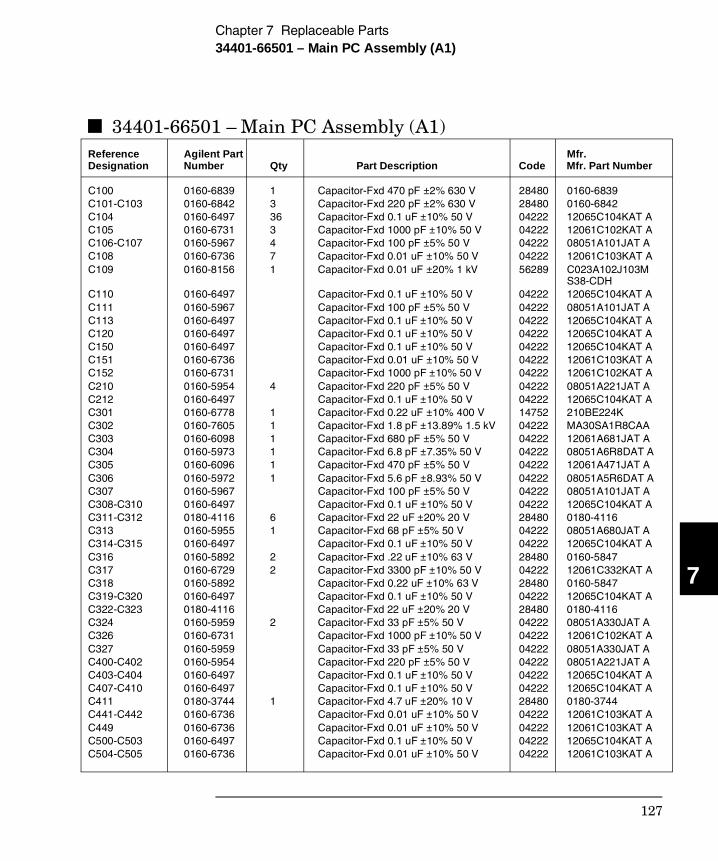
34401-66501 – Main PC Assembly (A1)Reference Agilent Part Mfr. Designation Number Qty Part Description Code Mfr. Part Number C100 0160-6839 1 Capacitor-Fxd 470 pF ±2% 630 V 28480 0160-6839 C101-C103 0160-6842 3 Capacitor-Fxd 220 pF ±2% 630 V 28480 0160-6842 C104 0160-6497 36 Capacitor-Fxd 0.1 uF ±10% 50 V 04222 12065C104KAT A C105 0160-6731 3 Capacitor-Fxd 1000 pF ±10% 50 V 04222 12061C102KAT A C106-C107 0160-5967 4 Capacitor-Fxd 100 pF ±5% 50 V 04222 08051A101JAT A C108 0160-6736 7 Capacitor-Fxd 0.01 uF ±10% 50 V 04222 12061C103KAT A C109 0160-8156 1 Capacitor-Fxd 0.01 uF ±20% 1 kV 56289 C023A102J103M
S38-CDH C110 0160-6497 Capacitor-Fxd 0.1 uF ±10% 50 V 04222 12065C104KAT AC111 0160-5967 Capacitor-Fxd 100 pF ±5% 50 V 04222 08051A101JAT A C113 0160-6497 Capacitor-Fxd 0.1 uF ±10% 50 V 04222 12065C104KAT A C120 0160-6497 Capacitor-Fxd 0.1 uF ±10% 50 V 04222 12065C104KAT A C150 0160-6497 Capacitor-Fxd 0.1 uF ±10% 50 V 04222 12065C104KAT A C151 0160-6736 Capacitor-Fxd 0.01 uF ±10% 50 V 04222 12061C103KAT A C152 0160-6731 Capacitor-Fxd 1000 pF ±10% 50 V 04222 12061C102KAT A C210 0160-5954 4 Capacitor-Fxd 220 pF ±5% 50 V 04222 08051A221JAT A C212 0160-6497 Capacitor-Fxd 0.1 uF ±10% 50 V 04222 12065C104KAT A C301 0160-6778 1 Capacitor-Fxd 0.22 uF ±10% 400 V 14752 210BE224K C302 0160-7605 1 Capacitor-Fxd 1.8 pF ±13.89% 1.5 kV 04222 MA30SA1R8CAA C303 0160-6098 1 Capacitor-Fxd 680 pF ±5% 50 V 04222 12061A681JAT A C304 0160-5973 1 Capacitor-Fxd 6.8 pF ±7.35% 50 V 04222 08051A6R8DAT A C305 0160-6096 1 Capacitor-Fxd 470 pF ±5% 50 V 04222 12061A471JAT AC306 0160-5972 1 Capacitor-Fxd 5.6 pF ±8.93% 50 V 04222 08051A5R6DAT A C307 0160-5967 Capacitor-Fxd 100 pF ±5% 50 V 04222 08051A101JAT A C308-C310 0160-6497 Capacitor-Fxd 0.1 uF ±10% 50 V 04222 12065C104KAT A C311-C312 0180-4116 6 Capacitor-Fxd 22 uF ±20% 20 V 28480 0180-4116 C313 0160-5955 1 Capacitor-Fxd 68 pF ±5% 50 V 04222 08051A680JAT A C314-C315 0160-6497 Capacitor-Fxd 0.1 uF ±10% 50 V 04222 12065C104KAT A C316 0160-5892 2 Capacitor-Fxd .22 uF ±10% 63 V 28480 0160-5847 C317 0160-6729 2 Capacitor-Fxd 3300 pF ±10% 50 V 04222 12061C332KAT A C318 0160-5892 Capacitor-Fxd 0.22 uF ±10% 63 V 28480 0160-5847 C319-C320 0160-6497 Capacitor-Fxd 0.1 uF ±10% 50 V 04222 12065C104KAT A C322-C323 0180-4116 Capacitor-Fxd 22 uF ±20% 20 V 28480 0180-4116 C324 0160-5959 2 Capacitor-Fxd 33 pF ±5% 50 V 04222 08051A330JAT A C326 0160-6731 Capacitor-Fxd 1000 pF ±10% 50 V 04222 12061C102KAT A C327 0160-5959 Capacitor-Fxd 33 pF ±5% 50 V 04222 08051A330JAT A C400-C402 0160-5954 Capacitor-Fxd 220 pF ±5% 50 V 04222 08051A221JAT A C403-C404 0160-6497 Capacitor-Fxd 0.1 uF ±10% 50 V 04222 12065C104KAT A C407-C410 0160-6497 Capacitor-Fxd 0.1 uF ±10% 50 V 04222 12065C104KAT A C411 0180-3744 1 Capacitor-Fxd 4.7 uF ±20% 10 V 28480 0180-3744 C441-C442 0160-6736 Capacitor-Fxd 0.01 uF ±10% 50 V 04222 12061C103KAT A C449 0160-6736 Capacitor-Fxd 0.01 uF ±10% 50 V 04222 12061C103KAT A C500-C503 0160-6497 Capacitor-Fxd 0.1 uF ±10% 50 V 04222 12065C104KAT A C504-C505 0160-6736 Capacitor-Fxd 0.01 uF ±10% 50 V 04222 12061C103KAT A
7
Chapter 7 Replaceable Parts34401-66501 – Main PC Assembly (A1)
127
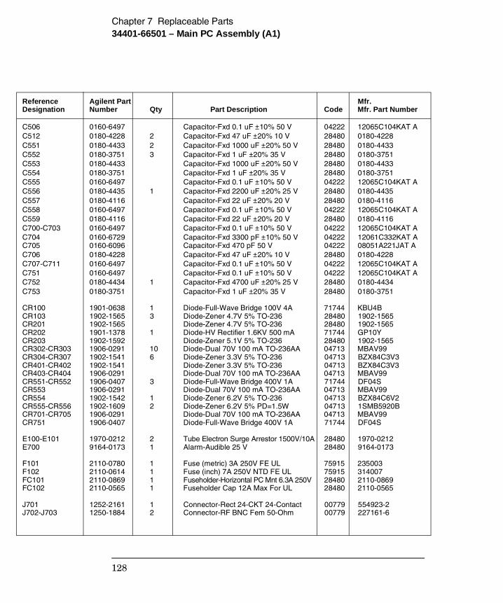
Reference Agilent Part Mfr. Designation Number Qty Part Description Code Mfr. Part Number C506 0160-6497 Capacitor-Fxd 0.1 uF ±10% 50 V 04222 12065C104KAT A C512 0180-4228 2 Capacitor-Fxd 47 uF ±20% 10 V 28480 0180-4228 C551 0180-4433 2 Capacitor-Fxd 1000 uF ±20% 50 V 28480 0180-4433 C552 0180-3751 3 Capacitor-Fxd 1 uF ±20% 35 V 28480 0180-3751 C553 0180-4433 Capacitor-Fxd 1000 uF ±20% 50 V 28480 0180-4433 C554 0180-3751 Capacitor-Fxd 1 uF ±20% 35 V 28480 0180-3751 C555 0160-6497 Capacitor-Fxd 0.1 uF ±10% 50 V 04222 12065C104KAT A C556 0180-4435 1 Capacitor-Fxd 2200 uF ±20% 25 V 28480 0180-4435 C557 0180-4116 Capacitor-Fxd 22 uF ±20% 20 V 28480 0180-4116 C558 0160-6497 Capacitor-Fxd 0.1 uF ±10% 50 V 04222 12065C104KAT A C559 0180-4116 Capacitor-Fxd 22 uF ±20% 20 V 28480 0180-4116 C700-C703 0160-6497 Capacitor-Fxd 0.1 uF ±10% 50 V 04222 12065C104KAT A C704 0160-6729 Capacitor-Fxd 3300 pF ±10% 50 V 04222 12061C332KAT A C705 0160-6096 Capacitor-Fxd 470 pF 50 V 04222 08051A221JAT A C706 0180-4228 Capacitor-Fxd 47 uF ±20% 10 V 28480 0180-4228 C707-C711 0160-6497 Capacitor-Fxd 0.1 uF ±10% 50 V 04222 12065C104KAT A C751 0160-6497 Capacitor-Fxd 0.1 uF ±10% 50 V 04222 12065C104KAT A C752 0180-4434 1 Capacitor-Fxd 4700 uF ±20% 25 V 28480 0180-4434 C753 0180-3751 Capacitor-Fxd 1 uF ±20% 35 V 28480 0180-3751 CR100 1901-0638 1 Diode-Full-Wave Bridge 100V 4A 71744 KBU4B CR103 1902-1565 3 Diode-Zener 4.7V 5% TO-236 28480 1902-1565 CR201 1902-1565 Diode-Zener 4.7V 5% TO-236 28480 1902-1565 CR202 1901-1378 1 Diode-HV Rectifier 1.6KV 500 mA 71744 GP10Y CR203 1902-1592 Diode-Zener 5.1V 5% TO-236 28480 1902-1565 CR302-CR303 1906-0291 10 Diode-Dual 70V 100 mA TO-236AA 04713 MBAV99 CR304-CR307 1902-1541 6 Diode-Zener 3.3V 5% TO-236 04713 BZX84C3V3 CR401-CR402 1902-1541 Diode-Zener 3.3V 5% TO-236 04713 BZX84C3V3 CR403-CR404 1906-0291 Diode-Dual 70V 100 mA TO-236AA 04713 MBAV99 CR551-CR552 1906-0407 3 Diode-Full-Wave Bridge 400V 1A 71744 DF04S CR553 1906-0291 Diode-Dual 70V 100 mA TO-236AA 04713 MBAV99 CR554 1902-1542 1 Diode-Zener 6.2V 5% TO-236 04713 BZX84C6V2 CR555-CR556 1902-1609 2 Diode-Zener 6.2V 5% PD=1.5W 04713 1SMB5920B CR701-CR705 1906-0291 Diode-Dual 70V 100 mA TO-236AA 04713 MBAV99 CR751 1906-0407 Diode-Full-Wave Bridge 400V 1A 71744 DF04S E100-E101 1970-0212 2 Tube Electron Surge Arrestor 1500V/10A 28480 1970-0212 E700 9164-0173 1 Alarm-Audible 25 V 28480 9164-0173 F101 2110-0780 1 Fuse (metric) 3A 250V FE UL 75915 235003 F102 2110-0614 1 Fuse (inch) 7A 250V NTD FE UL 75915 314007 FC101 2110-0869 1 Fuseholder-Horizontal PC Mnt 6.3A 250V 28480 2110-0869 FC102 2110-0565 1 Fuseholder Cap 12A Max For UL 28480 2110-0565 J701 1252-2161 1 Connector-Rect 24-CKT 24-Contact 00779 554923-2 J702-J703 1250-1884 2 Connector-RF BNC Fem 50-Ohm 00779 227161-6
Chapter 7 Replaceable Parts34401-66501 – Main PC Assembly (A1)
128
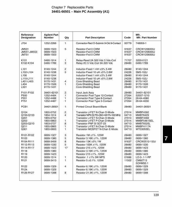
Reference Agilent Part Mfr. Designation Number Qty Part Description Code Mfr. Part Number J704 1252-2266 1 Connector-Rect D-Submin 9-Ckt 9-Contact 00779 748959-1
JM501 0699-1503 5 Resistor-Fxd 0 CWM 91637 CRCW1206000J JM551-JM553 0699-1503 Resistor-Fxd 0 CWM 91637 CRCW1206000J JM751 0699-1503 Resistor-Fxd 0 CWM 91637 CRCW1206000J K101 0490-1914 1 Relay-Reed 2A 500 Vdc 5 Vdc-Coil 71707 3200-0121K102-K104 0490-1789 3 Relay 2C 5 Vdc-Coil 3A 220 Vdc 28480 0490-1789 L101 9140-1244 2 Inductor-Fixed 1 mH ±5% 3.4W 28480 9140-1244 L102-L104 9140-1238 5 Inductor-Fixed 10 uH ±5% 2.8W 24226 SM3-102J L106 9140-1244 Inductor-Fixed 1 mH ±5% 3.4W 28480 9140-1244 L110-L111 9140-1238 Inductor-Fixed 10 uH ±5% 2.8W 24226 SM3-102J L401-L403 9170-1431 4 Core-Shielding Bead 28480 9170-1431 L404 9170-1506 1 Core-Shielding Bead 28480 9170-1506 L501 9170-1431 Core-Shielding Bead 28480 9170-1431 P101-P102 34401-62101 2 Input Jack Assy 28480 34401-62101P500 1252-4484 1 Connector Post Type 12-Contact 27264 52007-1210 P551 1252-4488 1 Connector Post Type 8-Contact 27264 26-64-4080 P751 1252-4487 1 Connector Post Type 3-Contact 27264 26-64-4030 PCB1 34401-26501 1 Printed Circuit Board-Blank 28480 34401-26501 Q104 1855-0752 2 Transistor J-FET N-Chan D-Mode 27014 MMBF4392 Q150-Q153 1854-1014 4 Transistor NPN SI PD=350 mW Ft=100 MHz 04713 MMBT6429 Q201 1855-0752 Transistor J-FET N-Chan D-Mode 27014 MMBF4392 Q202 1855-0863 1 Transistor J-FET P-Chan D-Mode 27014 MMBF5461SEL Q203-Q210 1853-0727 8 Transistor PNP SI SOT-23 04713 MMBT6520L Q211 1855-0865 1 Transistor J-FET N-Chan D-Mode 27014 MMBF4117A Q301 1855-0800 1 Transistor MOSFET N-Chan E-Mode 04713 MTD3055EL R101-R102 0699-1327 3 Resistor 1M ±1% .125W 28480 0699-1327 R103 0699-1380 5 Resistor 3.16K ±1% .125W 28480 0699-1380 R104-R111 0699-3409 8 Resistor 13K ±5% 1W 91637 CRCW2512-133J R112-R113 0699-1330 5 Resistor 100K ±1% .125W 28480 0699-1330 R114-R117 0699-1423 17 Resistor 215 ±1% .125W 28480 0699-1423 R118 0699-1380 Resistor 3.16K ±1% .125W 28480 0699-1380 R119 0699-1423 Resistor 215 ±1% .125W 28480 0699-1423 R120 0699-1514 1 Resistor .1 ±1% 5W MFS 01686 LO-5-.1-1-RP R121 0699-3413 1 Resistor 5 ±0.1% .125W 11502 CM60T13
5OHMS0.1 R122 0699-1329 4 Resistor 6.19K ±1% .125W 28480 0699-1329 R124 0699-1329 Resistor 6.19K ±1% .125W 28480 0699-1329 R126-R127 0699-1398 8 Resistor 21.5K ±1% .125W 28480 0699-1398
7
Chapter 7 Replaceable Parts34401-66501 – Main PC Assembly (A1)
129
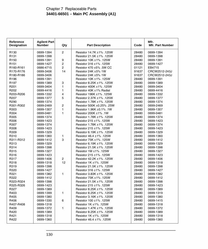
Reference Agilent Part Mfr. Designation Number Qty Part Description Code Mfr. Part Number R130 0699-1394 2 Resistor 14.7K ±1% .125W 28480 0699-1394 R131 0699-1398 Resistor 21.5K ±1% .125W 28480 0699-1398 R150 0699-1391 9 Resistor 10K ±1% .125W 28480 0699-1391 R151 0699-1427 2 Resistor 316 ±1% .125W 28480 0699-1427 R160-R161 0686-4715 2 Resistor 470 ±5% .5W CC 01121 EB4715 R170-R176 0699-3406 14 Resistor 24K ±5% 1W 91637 CRCW2512-243J R180-R186 0699-3406 Resistor 24K ±5% 1W 91637 CRCW2512-243J R196 0699-1391 Resistor 10K ±1% .125W 28480 0699-1391 R197 0699-1389 3 Resistor 8.25K ±1% .125W 28480 0699-1389 R201 0699-3404 1 Resistor 400K ±1% .125W 28480 0699-3404 R202 0699-4416 1 Resistor 40K ±1% Radial 28480 0699-4416 R203-R206 0699-1332 4 Resistor 196K ±1% .125W 28480 0699-1332 R207 0699-1377 5 Resistor 2.37K ±1% .125W 28480 0699-1377R290 0699-1374 Resistor 1.78K ±1% .125W 28480 0699-1374 R301-R302 0699-2469 2 Resistor 500K ±0.25% .25W 28480 0699-2469 R303 0699-1307 1 Resistor 1.96K ±0.1% .1W 28480 0699-1307 R304 0699-0481 1 Resistor 200K ±1% .1W 28480 0699-0481 R305 0699-1374 Resistor 1.78K ±1% .125W 28480 0699-1374 R306 0699-1423 Resistor 215 ±1% .125W 28480 0699-1423 R307 0699-1374 Resistor 1.78K ±1% .125W 28480 0699-1374 R308 0699-1423 Resistor 215 ±1% .125W 28480 0699-1423 R309 0699-1329 Resistor 6.19K ±1% .125W 28480 0699-1329 R310 0699-1360 1 Resistor 46.4 ±1% .125W 28480 0699-1360 R311-R312 0699-1412 3 Resistor 75K ±1% .125W 28480 0699-1412 R313 0699-1329 Resistor 6.19K ±1% .125W 28480 0699-1329 R314 0699-1398 Resistor 21.5K ±1% .125W 28480 0699-1398 R315 0699-1327 Resistor 1M ±1% .125W 28480 0699-1327 R316 0699-1423 Resistor 215 ±1% .125W 28480 0699-1423 R317 0699-1406 2 Resistor 42.2K ±1% .125W 28480 0699-1406 R318 0699-1318 12 Resistor 1K ±1% .125W 28480 0699-1318 R319 0699-1398 Resistor 21.5K ±1% .125W 28480 0699-1398 R320 0699-1427 Resistor 316 ±1% .125W 28480 0699-1427 R321 0699-1382 1 Resistor 3.83K ±1% .125W 28480 0699-1382 R322 0699-1412 Resistor 75K ±1% .125W 28480 0699-1412 R323-R324 0699-1398 Resistor 21.5K ±1% .125W 28480 0699-1398 R325-R326 0699-1423 Resistor 215 ±1% .125W 28480 0699-1423 R327 0699-1389 Resistor 8.25K ±1% .125W 28480 0699-1389 R403 0699-1399 1 Resistor 8.25K ±1% .125W 28480 0699-1319 R405 0699-1380 Resistor 3.16K ±1% .125W 28480 0699-1380 R406 0699-1330 6 Resistor 100 ±1% .125W 28480 0699-1415 R407-R408 0699-1318 Resistor 1K ±1% .125W 28480 0699-1318 R409 0699-1372 1 Resistor 1.47K ±1% .125W 28480 0699-1372 R420 0699-1389 Resistor 8.25K ±1% .125W 28480 0699-1389 R421 0699-1318 Resistor 1K ±1% .125W 28480 0699-1318R422 0699-1360 Resistor 46.4 ±1% .125W 28480 0699-1360
Chapter 7 Replaceable Parts34401-66501 – Main PC Assembly (A1)
130
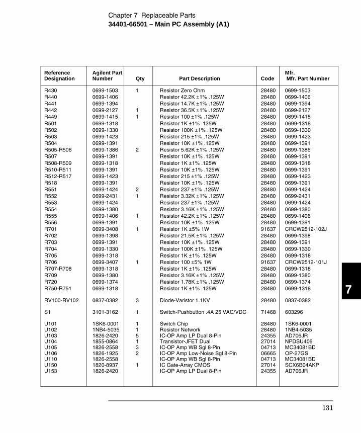
Reference Agilent Part Mfr. Designation Number Qty Part Description Code Mfr. Part Number R430 0699-1503 1 Resistor Zero Ohm 28480 0699-1503 R440 0699-1406 Resistor 42.2K ±1% .125W 28480 0699-1406 R441 0699-1394 Resistor 14.7K ±1% .125W 28480 0699-1394 R442 0699-2127 1 Resistor 36.5K ±1% .125W 28480 0699-2127 R449 0699-1415 1 Resistor 100 ±1% .125W 28480 0699-1415 R501 0699-1318 Resistor 1K ±1% .125W 28480 0699-1318 R502 0699-1330 Resistor 100K ±1% .125W 28480 0699-1330 R503 0699-1423 Resistor 215 ±1% .125W 28480 0699-1423 R504 0699-1391 Resistor 10K ±1% .125W 28480 0699-1391 R505-R506 0699-1386 2 Resistor 5.62K ±1% .125W 28480 0699-1386 R507 0699-1391 Resistor 10K ±1% .125W 28480 0699-1391 R508-R509 0699-1318 Resistor 1K ±1% .125W 28480 0699-1318 R510-R511 0699-1391 Resistor 10K ±1% .125W 28480 0699-1391 R512-R517 0699-1423 Resistor 215 ±1% .125W 28480 0699-1423 R518 0699-1391 Resistor 10K ±1% .125W 28480 0699-1391 R551 0699-1424 2 Resistor 237 ±1% .125W 28480 0699-1424 R552 0699-2431 1 Resistor 3.32K ±1% .125W 28480 0699-2431 R553 0699-1424 Resistor 237 ±1% .125W 28480 0699-1424 R554 0699-1380 Resistor 3.16K ±1% .125W 28480 0699-1380 R555 0699-1406 1 Resistor 42.2K ±1% .125W 28480 0699-1406 R556 0699-1391 Resistor 10K ±1% .125W 28480 0699-1391 R701 0699-3408 1 Resistor 1K ±5% 1W 91637 CRCW2512-102J R702 0699-1398 Resistor 21.5K ±1% .125W 28480 0699-1398 R703 0699-1391 Resistor 10K ±1% .125W 28480 0699-1391 R704 0699-1330 Resistor 100K ±1% .125W 28480 0699-1330 R705 0699-1318 Resistor 1K ±1% .125W 28480 0699-1318 R706 0699-3407 1 Resistor 100 ±5% 1W 91637 CRCW2512-101J R707-R708 0699-1318 Resistor 1K ±1% .125W 28480 0699-1318 R709 0699-1380 Resistor 3.16K ±1% .125W 28480 0699-1380 R720 0699-1374 Resistor 1.78K ±1% .125W 28480 0699-1374 R750-R751 0699-1318 Resistor 1K ±1% .125W 28480 0699-1318 RV100-RV102 0837-0382 3 Diode-Varistor 1.1KV 28480 0837-0382 S1 3101-3162 1 Switch-Pushbutton .4A 25 VAC/VDC 71468 603296 U101 1SK6-0001 1 Switch Chip 28480 1SK6-0001 U102 1NB4-5035 1 Resistor Network 28480 1NB4-5035U103 1826-2420 5 IC-OP Amp LP Dual 8-Pin 24355 AD706JR U104 1855-0864 1 Transistor-JFET Dual 27014 NPDSU406 U105 1826-2558 3 IC-OP Amp WB Sgl 8-Pin 04713 MC34081BD U106 1826-1925 2 IC-OP Amp Low-Noise Sgl 8-Pin 06665 OP-27GS U110 1826-2558 IC-OP Amp WB Sgl 8-Pin 04713 MC34081BD U150 1820-8937 1 IC Gate-Array CMOS 27014 SCX6B04AKP U153 1826-2420 IC-OP Amp LP Dual 8-Pin 24355 AD706JR
7
Chapter 7 Replaceable Parts34401-66501 – Main PC Assembly (A1)
131
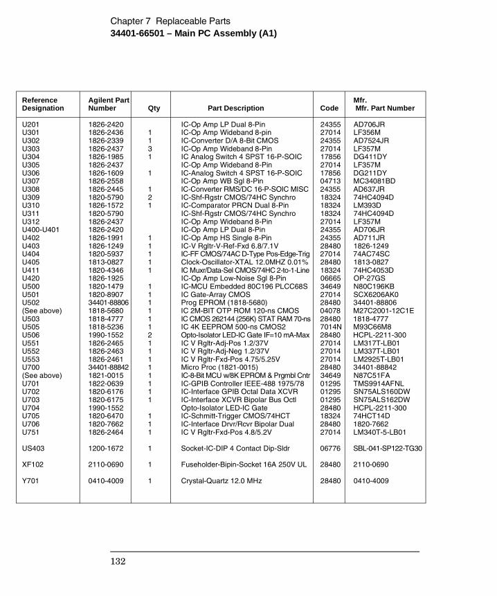
Reference Agilent Part Mfr. Designation Number Qty Part Description Code Mfr. Part Number U201 1826-2420 IC-Op Amp LP Dual 8-Pin 24355 AD706JRU301 1826-2436 1 IC-Op Amp Wideband 8-pin 27014 LF356M U302 1826-2339 1 IC-Converter D/A 8-Bit CMOS 24355 AD7524JR U303 1826-2437 3 IC-Op Amp Wideband 8-Pin 27014 LF357M U304 1826-1985 1 IC Analog Switch 4 SPST 16-P-SOIC 17856 DG411DY U305 1826-2437 IC-Op Amp Wideband 8-Pin 27014 LF357M U306 1826-1609 1 IC-Analog Switch 4 SPST 16-P-SOIC 17856 DG211DY U307 1826-2558 IC-Op Amp WB Sgl 8-Pin 04713 MC34081BD U308 1826-2445 1 IC-Converter RMS/DC 16-P-SOIC MISC 24355 AD637JR U309 1820-5790 2 IC-Shf-Rgstr CMOS/74HC Synchro 18324 74HC4094D U310 1826-1572 1 IC-Comparator PRCN Dual 8-Pin 18324 LM393D U311 1820-5790 IC-Shf-Rgstr CMOS/74HC Synchro 18324 74HC4094D U312 1826-2437 IC-Op Amp Wideband 8-Pin 27014 LF357M U400-U401 1826-2420 IC-Op Amp LP Dual 8-Pin 24355 AD706JR U402 1826-1991 1 IC-Op Amp HS Single 8-Pin 24355 AD711JR U403 1826-1249 1 IC-V Rgltr-V-Ref-Fxd 6.8/7.1V 28480 1826-1249 U404 1820-5937 1 IC-FF CMOS/74AC D-Type Pos-Edge-Trig 27014 74AC74SC U405 1813-0827 1 Clock-Oscillator-XTAL 12.0MHZ 0.01% 28480 1813-0827 U411 1820-4346 1 IC Muxr/Data-Sel CMOS/74HC 2-to-1-Line 18324 74HC4053D U420 1826-1925 IC-Op Amp Low-Noise Sgl 8-Pin 06665 OP-27GS U500 1820-1479 1 IC-MCU Embedded 80C196 PLCC68S 34649 N80C196KB U501 1820-8907 1 IC Gate-Array CMOS 27014 SCX6206AK0U502 34401-88806 1 Prog EPROM (1818-5680) 28480 34401-88806(See above) 1818-5680 1 IC 2M-BIT OTP ROM 120-ns CMOS 04078 M27C2001-12C1EU503 1818-4777 1 IC CMOS 262144 (256K) STAT RAM 70-ns 28480 1818-4777 U505 1818-5236 1 IC 4K EEPROM 500-ns CMOS2 7014N M93C66M8 U506 1990-1552 2 Opto-Isolator LED-IC Gate IF=10 mA-Max 28480 HCPL-2211-300 U551 1826-2465 1 IC V Rgltr-Adj-Pos 1.2/37V 27014 LM317T-LB01 U552 1826-2463 1 IC V Rgltr-Adj-Neg 1.2/37V 27014 LM337T-LB01 U553 1826-2461 1 IC V Rgltr-Fxd-Pos 4.75/5.25V 27014 LM2925T-LB01 U700 34401-88842 1 Micro Proc (1821-0015) 28480 34401-88842(See above) 1821-0015 1 IC-8-Bit MCU w/8K EPROM & Prgmbl Cntr 34649 N87C51FA U701 1822-0639 1 IC-GPIB Controller IEEE-488 1975/78 01295 TMS9914AFNL U702 1820-6176 1 IC-Interface GPIB Octal Data XCVR 01295 SN75ALS160DW U703 1820-6175 1 IC-Interface XCVR Bipolar Bus Octl 01295 SN75ALS162DW U704 1990-1552 Opto-Isolator LED-IC Gate 28480 HCPL-2211-300 U705 1820-6470 1 IC-Schmitt-Trigger CMOS/74HCT 18324 74HCT14D U706 1820-7662 1 IC-Interface Drvr/Rcvr Bipolar Dual 28480 1820-7662 U751 1826-2464 1 IC V Rgltr-Fxd-Pos 4.8/5.2V 27014 LM340T-5-LB01 US403 1200-1672 1 Socket-IC-DIP 4 Contact Dip-Sldr 06776 SBL-041-SP122-TG30
XF102 2110-0690 1 Fuseholder-Bipin-Socket 16A 250V UL 28480 2110-0690
Y701 0410-4009 1 Crystal-Quartz 12.0 MHz 28480 0410-4009
Chapter 7 Replaceable Parts34401-66501 – Main PC Assembly (A1)
132
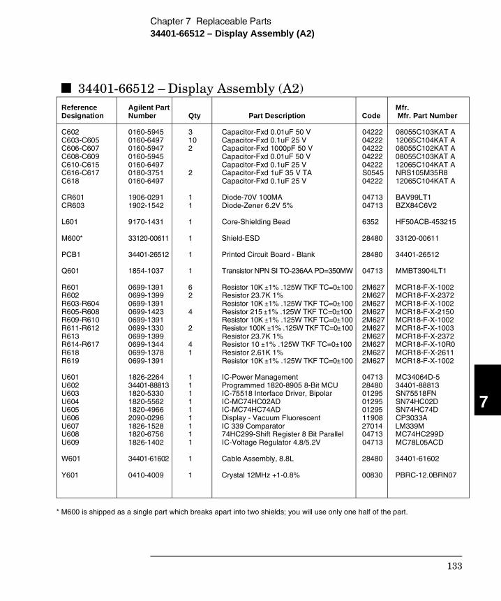
34401-66512 – Display Assembly (A2)Reference Agilent Part Mfr. Designation Number Qty Part Description Code Mfr. Part Number
C602 0160-5945 3 Capacitor-Fxd 0.01uF 50 V 04222 08055C103KAT A C603-C605 0160-6497 10 Capacitor-Fxd 0.1uF 25 V 04222 12065C104KAT A C606-C607 0160-5947 2 Capacitor-Fxd 1000pF 50 V 04222 08055C102KAT A C608-C609 0160-5945 Capacitor-Fxd 0.01uF 50 V 04222 08055C103KAT AC610-C615 0160-6497 Capacitor-Fxd 0.1uF 25 V 04222 12065C104KAT AC616-C617 0180-3751 2 Capacitor-Fxd 1uF 35 V TA S0545 NRS105M35R8 C618 0160-6497 Capacitor-Fxd 0.1uF 25 V 04222 12065C104KAT A
CR601 1906-0291 1 Diode-70V 100MA 04713 BAV99LT1 CR603 1902-1542 1 Diode-Zener 6.2V 5% 04713 BZX84C6V2
L601 9170-1431 1 Core-Shielding Bead 6352 HF50ACB-453215
M600* 33120-00611 1 Shield-ESD 28480 33120-00611
PCB1 34401-26512 1 Printed Circuit Board - Blank 28480 34401-26512
Q601 1854-1037 1 Transistor NPN SI TO-236AA PD=350MW 04713 MMBT3904LT1
R601 0699-1391 6 Resistor 10K ±1% .125W TKF TC=0±100 2M627 MCR18-F-X-1002 R602 0699-1399 2 Resistor 23.7K 1% 2M627 MCR18-F-X-2372 R603-R604 0699-1391 Resistor 10K ±1% .125W TKF TC=0±100 2M627 MCR18-F-X-1002 R605-R608 0699-1423 4 Resistor 215 ±1% .125W TKF TC=0±100 2M627 MCR18-F-X-2150 R609-R610 0699-1391 Resistor 10K ±1% .125W TKF TC=0±100 2M627 MCR18-F-X-1002R611-R612 0699-1330 2 Resistor 100K ±1% .125W TKF TC=0±100 2M627 MCR18-F-X-1003 R613 0699-1399 Resistor 23.7K 1% 2M627 MCR18-F-X-2372 R614-R617 0699-1344 4 Resistor 10 ±1% .125W TKF TC=0±100 2M627 MCR18-F-X-10R0 R618 0699-1378 1 Resistor 2.61K 1% 2M627 MCR18-F-X-2611 R619 0699-1391 Resistor 10K ±1% .125W TKF TC=0±100 2M627 MCR18-F-X-1002
U601 1826-2264 1 IC-Power Management 04713 MC34064D-5 U602 34401-88813 1 Programmed 1820-8905 8-Bit MCU 28480 34401-88813 U603 1820-5330 1 IC-75518 Interface Driver, Bipolar 01295 SN75518FN U604 1820-5562 1 IC-MC74HC02AD 01295 SN74HC02D U605 1820-4966 1 IC-MC74HC74AD 01295 SN74HC74D U606 2090-0296 1 Display - Vacuum Fluorescent 11908 CP3033A U607 1826-1528 1 IC 339 Comparator 27014 LM339M U608 1820-6756 1 74HC299-Shift Register 8 Bit Parallel 04713 MC74HC299D U609 1826-1402 1 IC-Voltage Regulator 4.8/5.2V 04713 MC78L05ACD
W601 34401-61602 1 Cable Assembly, 8.8L 28480 34401-61602
Y601 0410-4009 1 Crystal 12MHz +1-0.8% 00830 PBRC-12.0BRN07
* M600 is shipped as a single part which breaks apart into two shields; you will use only one half of the part.
7
Chapter 7 Replaceable Parts34401-66512 – Display Assembly (A2)
133
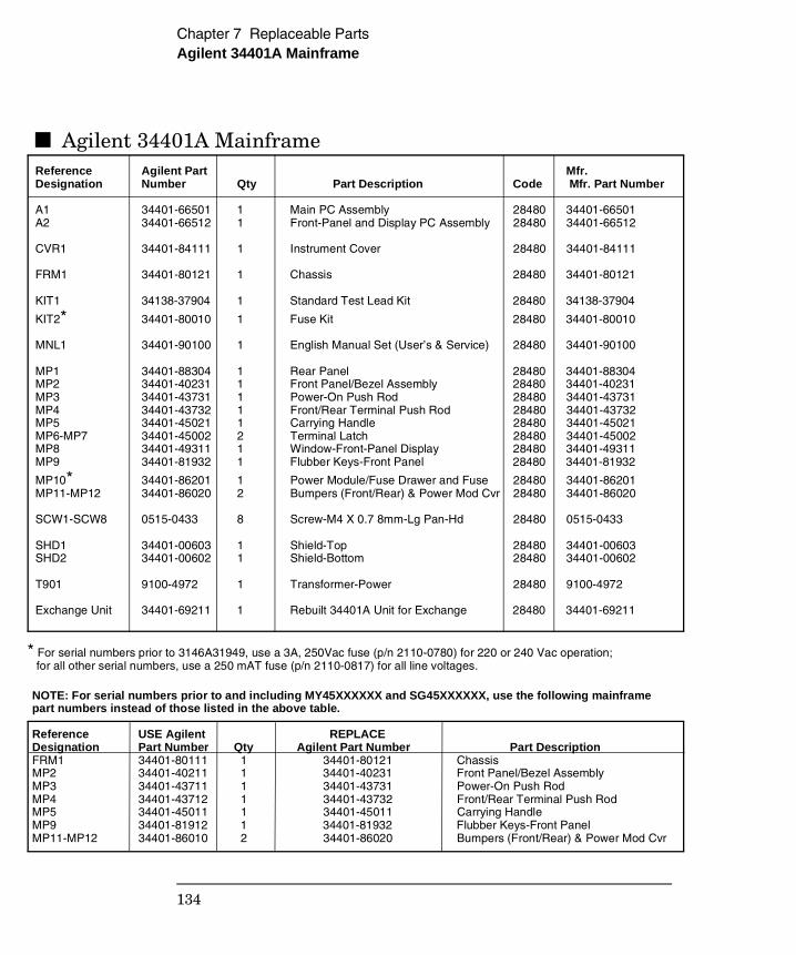
Agilent 34401A Mainframe Reference Agilent Part Mfr. Designation Number Qty Part Description Code Mfr. Part Number A1 34401-66501 1 Main PC Assembly 28480 34401-66501A2 34401-66512 1 Front-Panel and Display PC Assembly 28480 34401-66512
CVR1 34401-84111 1 Instrument Cover 28480 34401-84111
FRM1 34401-80121 1 Chassis 28480 34401-80121
KIT1 34138-37904 1 Standard Test Lead Kit 28480 34138-37904
KIT2* 34401-80010 1 Fuse Kit 28480 34401-80010
MNL1 34401-90100 1 English Manual Set (User’s & Service) 28480 34401-90100
MP1 34401-88304 1 Rear Panel 28480 34401-88304MP2 34401-40231 1 Front Panel/Bezel Assembly 28480 34401-40231MP3 34401-43731 1 Power-On Push Rod 28480 34401-43731MP4 34401-43732 1 Front/Rear Terminal Push Rod 28480 34401-43732MP5 34401-45021 1 Carrying Handle 28480 34401-45021MP6-MP7 34401-45002 2 Terminal Latch 28480 34401-45002MP8 34401-49311 1 Window-Front-Panel Display 28480 34401-49311MP9 34401-81932 1 Flubber Keys-Front Panel 28480 34401-81932
MP10* 34401-86201 1 Power Module/Fuse Drawer and Fuse 28480 34401-86201MP11-MP12 34401-86020 2 Bumpers (Front/Rear) & Power Mod Cvr 28480 34401-86020
SCW1-SCW8 0515-0433 8 Screw-M4 X 0.7 8mm-Lg Pan-Hd 28480 0515-0433
SHD1 34401-00603 1 Shield-Top 28480 34401-00603SHD2 34401-00602 1 Shield-Bottom 28480 34401-00602
T901 9100-4972 1 Transformer-Power 28480 9100-4972
Exchange Unit 34401-69211 1 Rebuilt 34401A Unit for Exchange 28480 34401-69211
* For serial numbers prior to 3146A31949, use a 3A, 250Vac fuse (p/n 2110-0780) for 220 or 240 Vac operation; for all other serial numbers, use a 250 mAT fuse (p/n 2110-0817) for all line voltages.
NOTE: For serial numbers prior to and including MY45XXXXXX and SG45XXXXXX, use the following mainframepart numbers instead of those listed in the above table.
Reference USE Agilent REPLACEDesignation Part Number Qty Agilent Part Number Part DescriptionFRM1 34401-80111 1 34401-80121 Chassis MP2 34401-40211 1 34401-40231 Front Panel/Bezel AssemblyMP3 34401-43711 1 34401-43731 Power-On Push RodMP4 34401-43712 1 34401-43732 Front/Rear Terminal Push RodMP5 34401-45011 1 34401-45011 Carrying HandleMP9 34401-81912 1 34401-81932 Flubber Keys-Front PanelMP11-MP12 34401-86010 2 34401-86020 Bumpers (Front/Rear) & Power Mod Cvr
Chapter 7 Replaceable PartsAgilent 34401A Mainframe
134
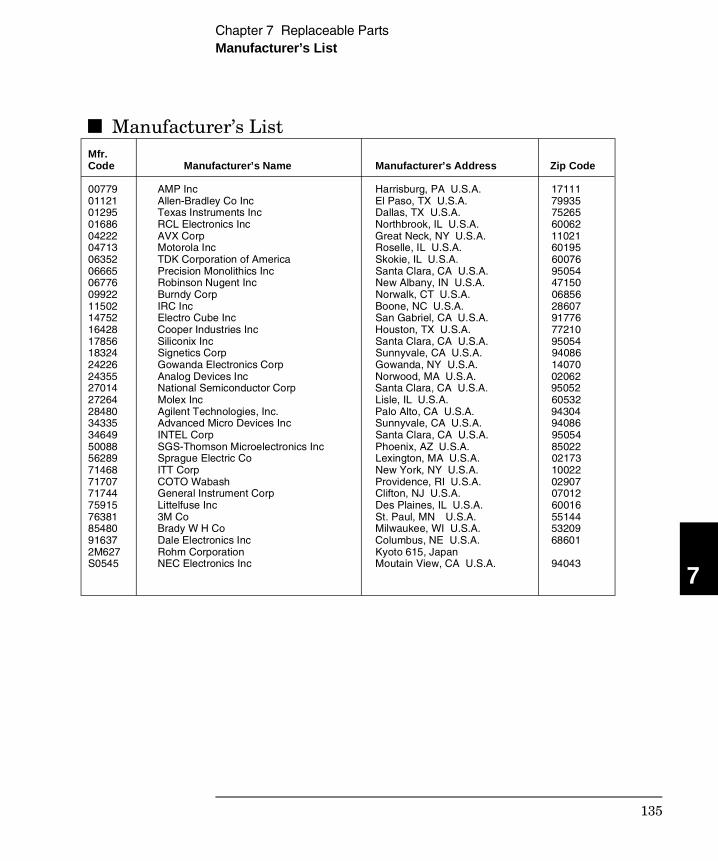
Manufacturer’s ListMfr. Code Manufacturer’s Name Manufacturer’s Address Zip Code 00779 AMP Inc Harrisburg, PA U.S.A. 17111 01121 Allen-Bradley Co Inc El Paso, TX U.S.A. 7993501295 Texas Instruments Inc Dallas, TX U.S.A. 7526501686 RCL Electronics Inc Northbrook, IL U.S.A. 6006204222 AVX Corp Great Neck, NY U.S.A. 1102104713 Motorola Inc Roselle, IL U.S.A. 60195 06352 TDK Corporation of America Skokie, IL U.S.A. 6007606665 Precision Monolithics Inc Santa Clara, CA U.S.A. 9505406776 Robinson Nugent Inc New Albany, IN U.S.A. 4715009922 Burndy Corp Norwalk, CT U.S.A. 0685611502 IRC Inc Boone, NC U.S.A. 28607 14752 Electro Cube Inc San Gabriel, CA U.S.A. 9177616428 Cooper Industries Inc Houston, TX U.S.A. 7721017856 Siliconix Inc Santa Clara, CA U.S.A. 95054 18324 Signetics Corp Sunnyvale, CA U.S.A. 94086 24226 Gowanda Electronics Corp Gowanda, NY U.S.A. 14070 24355 Analog Devices Inc Norwood, MA U.S.A. 02062 27014 National Semiconductor Corp Santa Clara, CA U.S.A. 95052 27264 Molex Inc Lisle, IL U.S.A. 60532 28480 Agilent Technologies, Inc. Palo Alto, CA U.S.A. 9430434335 Advanced Micro Devices Inc Sunnyvale, CA U.S.A. 9408634649 INTEL Corp Santa Clara, CA U.S.A. 95054 50088 SGS-Thomson Microelectronics Inc Phoenix, AZ U.S.A. 85022 56289 Sprague Electric Co Lexington, MA U.S.A. 02173 71468 ITT Corp New York, NY U.S.A. 1002271707 COTO Wabash Providence, RI U.S.A. 02907 71744 General Instrument Corp Clifton, NJ U.S.A. 07012 75915 Littelfuse Inc Des Plaines, IL U.S.A. 6001676381 3M Co St. Paul, MN U.S.A. 5514485480 Brady W H Co Milwaukee, WI U.S.A. 53209 91637 Dale Electronics Inc Columbus, NE U.S.A. 68601 2M627 Rohm Corporation Kyoto 615, JapanS0545 NEC Electronics Inc Moutain View, CA U.S.A. 94043
7
Chapter 7 Replaceable PartsManufacturer’s List
135

136
8
Backdating
8
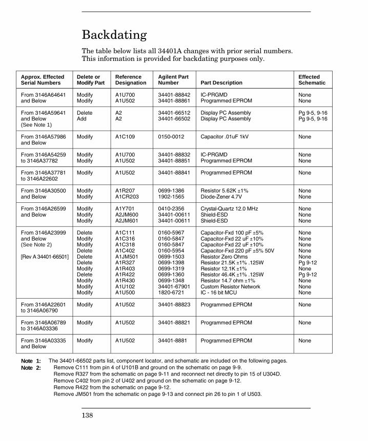
Backdating
The table below lists all 34401A changes with prior serial numbers. This information is provided for backdating purposes only.
Approx. EffectedSerial Numbers
From 3146A64641and Below
From 3146A59641and Below(See Note 1)
From 3146A57986and Below
From 3146A54259to 3146A37782
From 3146A37781to 3146A22602
From 3146A30500and Below
From 3146A26599and Below
From 3146A23999and Below(See Note 2)
[Rev A 34401-66501]
From 3146A22601to 3146A06790
From 3146A06789to 3146A03336
From 3146A03335and Below
Delete orModify Part
ModifyModify
DeleteAdd
Modify
ModifyModify
Modify
ModifyModify
ModifyModifyModify
DeleteModifyModifyDeleteDeleteDeleteModifyDeleteModifyModifyModify
Modify
Modify
Modify
ReferenceDesignation
A1U700A1U502
A2A2
A1C109
A1U700A1U502
A1U502
A1R207A1CR203
A1Y701A2JM600A2JM601
A1C111A1C316A1C318A1C402A1JM501A1R327A1R403A1R422A1R430A1U102A1U500
A1U502
A1U502
A1U502
Agilent PartNumber
34401-8884234401-88861
34401-6651234401-66502
0150-0012
34401-8883234401-88851
34401-88841
0699-13861902-1565
0410-235634401-0061134401-00611
0160-59670160-58470160-58470160-59540699-15030699-13980699-13190699-13600699-134834401-679011820-6721
34401-88823
34401-88821
34401-8881
Part Description
IC-PRGMDProgrammed EPROM
Display PC AssemblyDisplay PC Assembly
Capacitor .01uF 1kV
IC-PRGMDProgrammed EPROM
Programmed EPROM
Resistor 5.62K ±1%Diode-Zener 4.7V
Crystal-Quartz 12.0 MHzShield-ESDShield-ESD
Capacitor-Fxd 100 pF ±5%Capacitor-Fxd 22 uF ±10%Capacitor-Fxd 22 uF ±10%Capacitor-Fxd 220 pF ±5% 50VResistor Zero OhmsResistor 21.5K ±1% .125WResistor 12.1K ±1%Resistor 46.4K ±1% .125WResistor 14.7 ohm ±1%Custom Resistor NetworkIC - 16 bit MCU
Programmed EPROM
Programmed EPROM
Programmed EPROM
Effected Schematic
NoneNone
Pg 9-5, 9-16Pg 9-5, 9-16
None
NoneNone
None
NoneNone
NoneNoneNone
NoneNoneNoneNoneNonePg 9-12NonePg 9-12NoneNoneNone
None
None
None
Note 1:Note 2:
The 34401-66502 parts list, component locator, and schematic are included on the following pages. Remove C111 from pin 4 of U101B and ground on the schematic on page 9-9. Remove R327 from the schematic on page 9-11 and reconnect net directly to pin 15 of U304D. Remove C402 from pin 2 of U402 and ground on the schematic on page 9-12. Remove R422 from the schematic on page 9-12. Remove JM501 from the schematic on page 9-13 and connect pin 26 to pin 1 of U503.
138
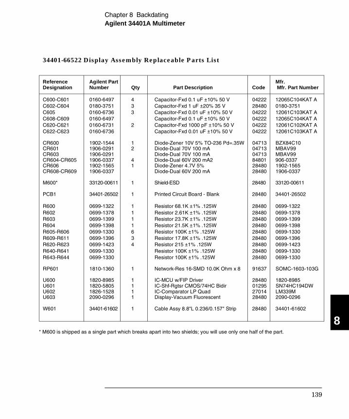
34401-66522 Display Assembly Replaceable Parts List
Reference Agilent Part Mfr. Designation Number Qty Part Description Code Mfr. Part Number C600-C601 0160-6497 4 Capacitor-Fxd 0.1 uF ±10% 50 V 04222 12065C104KAT AC602-C604 0180-3751 3 Capacitor-Fxd 1 uF ±20% 35 V 28480 0180-3751C605 0160-6736 3 Capacitor-Fxd 0.01 uF ±10% 50 V 04222 12061C103KAT A C608-C609 0160-6497 Capacitor-Fxd 0.1 uF ±10% 50 V 04222 12065C104KAT AC620-C621 0160-6731 2 Capacitor-Fxd 1000 pF ±10% 50 V 04222 12061C102KAT AC622-C623 0160-6736 Capacitor-Fxd 0.01 uF ±10% 50 V 04222 12061C103KAT A CR600 1902-1544 1 Diode-Zener 10V 5% TO-236 Pd=.35W 04713 BZX84C10 CR601 1906-0291 2 Diode-Dual 70V 100 mA 04713 MBAV99 CR603 1906-0291 Diode-Dual 70V 100 mA 04713 MBAV99 CR604-CR605 1906-0337 4 Diode-Dual 60V 200 mA2 84801 906-0337 CR606 1902-1565 1 Diode-Zener 4.7V 5% 28480 1902-1565 CR608-CR609 1906-0337 Diode-Dual 60V 200 mA 28480 1906-0337
M600* 33120-00611 1 Shield-ESD 28480 33120-00611 PCB1 34401-26502 1 Printed Circuit Board - Blank 28480 34401-26502 R600 0699-1322 1 Resistor 68.1K ±1% .125W 28480 0699-1322 R602 0699-1378 1 Resistor 2.61K ±1% .125W 28480 0699-1378 R603 0699-1399 1 Resistor 23.7K ±1% .125W 28480 0699-1399 R604 0699-1398 1 Resistor 21.5K ±1% .125W 28480 0699-1398 R605-R606 0699-1330 6 Resistor 100K ±1% .125W 28480 0699-1330 R609-R611 0699-1396 3 Resistor 17.8K ±1% .125W 28480 0699-1396 R620-R623 0699-1423 4 Resistor 215 ±1% .125W 28480 0699-1423 R640-R641 0699-1330 Resistor 100K ±1% .125W 28480 0699-1330 R643-R644 0699-1330 Resistor 100K ±1% .125W 28480 0699-1330 RP601 1810-1360 1 Network-Res 16-SMD 10.0K Ohm x 8 91637 SOMC-1603-103G U600 1820-8985 1 IC-MCU w/FIP Driver 28480 1820-8985U601 1820-5805 1 IC-Shf-Rgtsr CMOS/74HC Bidir 01295 SN74HC194DWU602 1826-1528 1 IC-Comparator LP Quad 27014 LM339M U603 2090-0296 1 Display-Vacuum Fluorescent 28480 2090-0296 W601 34401-61602 1 Cable Assy 8.8"L 0.236/0.157" Strip 28480 34401-61602
* M600 is shipped as a single part which breaks apart into two shields; you will use only one half of the part.
8
Chapter 8 BackdatingAgilent 34401A Multimeter
139
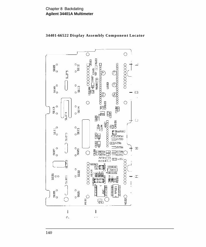
34401-66522 Display Assembly Component Locator
Chapter 8 BackdatingAgilent 34401A Multimeter
140
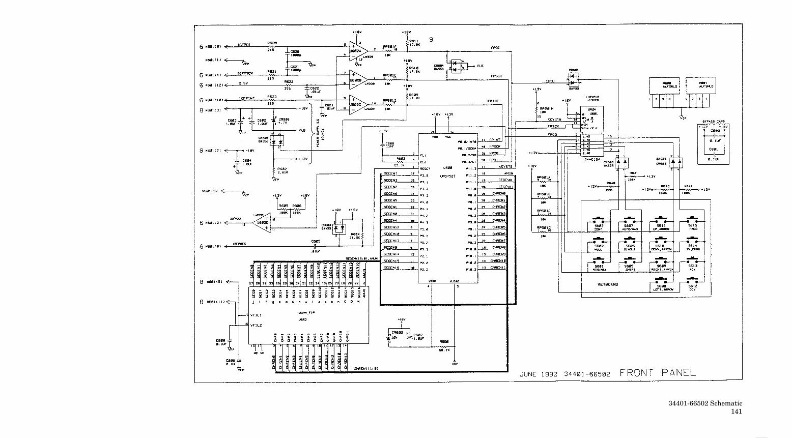
34401-66502 Schematic141
9
Schematics 9
Schematics
• Mechanical Disassembly 9-3• Component Locator Diagram – Main Board (34401-66501) 9-5• Component Locator Diagram – Front Panel (34401-66512) 9-6• Agilent 34401A Block Diagram 9-7• Front/Rear Selection Schematic 9-8• Function Switching Schematic 9-9• DC Amplifier and Ohms Schematic 9-10• AC Circuit Schematic 9-11• A/D Converter Schematic 9-12• Floating Logic Schematic 9-13• Earth-Referenced Logic Schematic 9-14• Power Supplies Schematic 9-15• Front-Panel Display and Keyboard Schematic 9-16
9-2
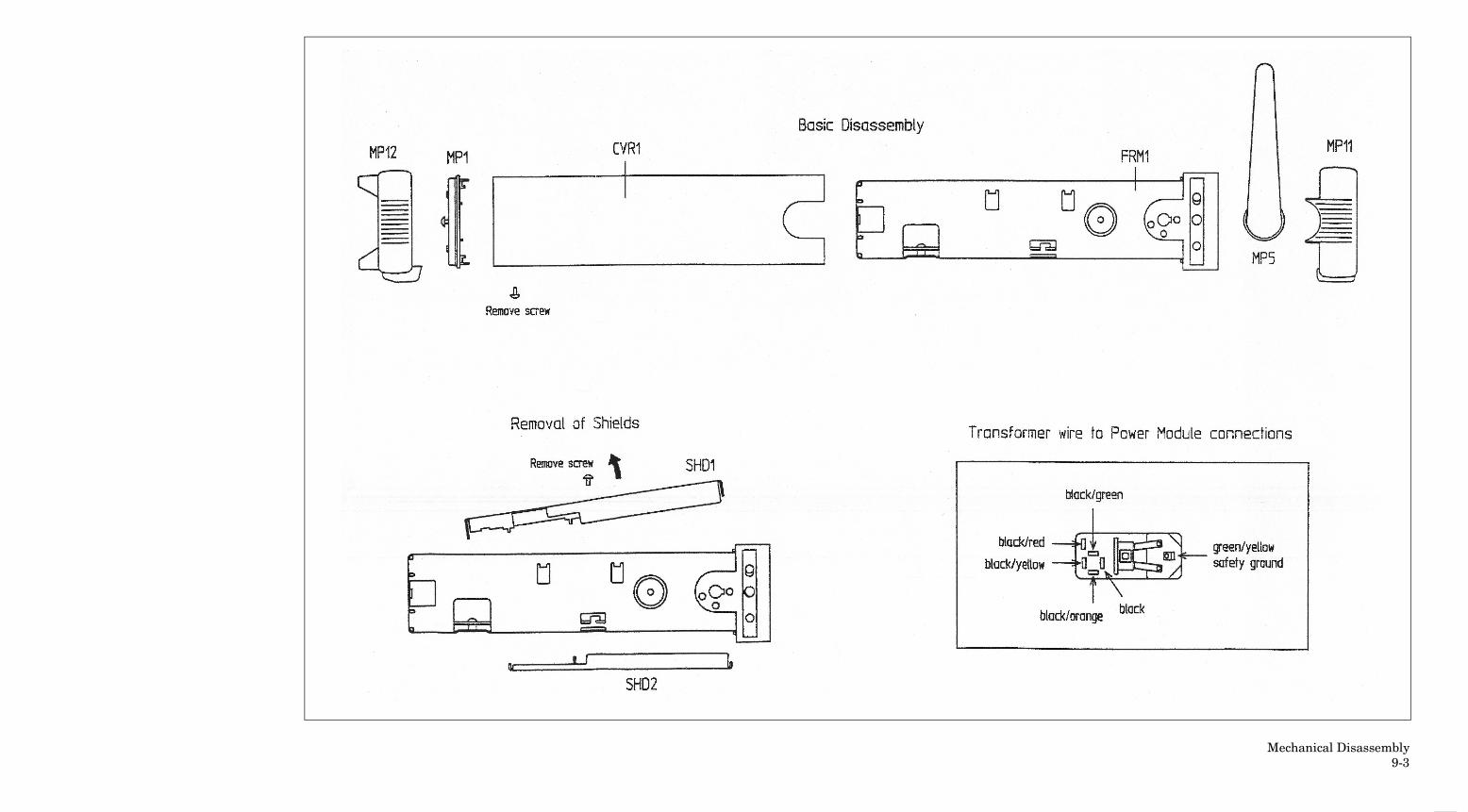
Mechanical Disassembly9-3
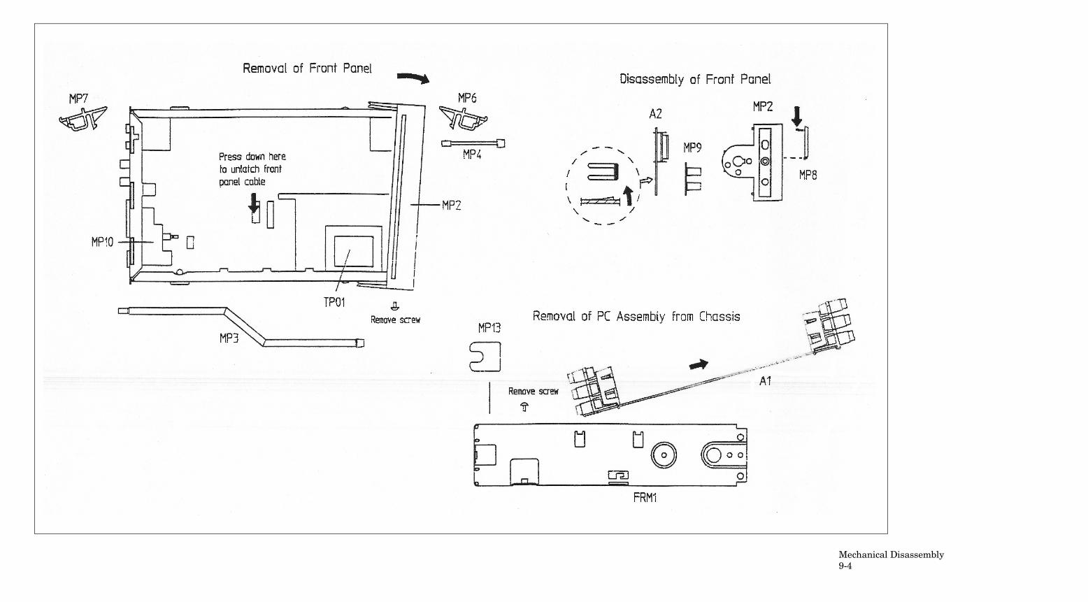
Mechanical Disassembly9-4
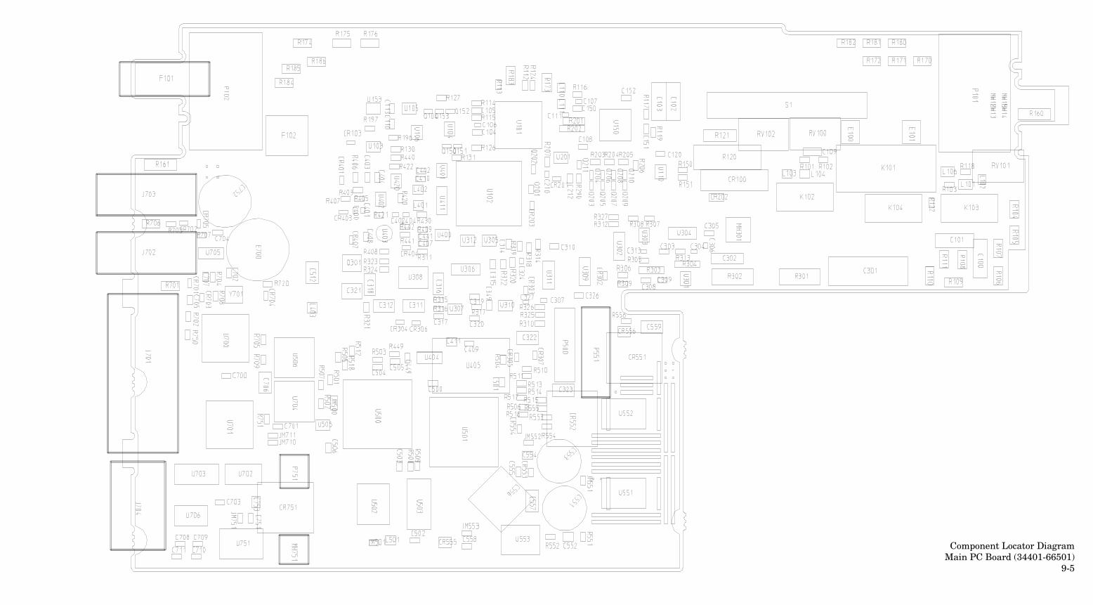
Component Locator DiagramMain PC Board (34401-66501)
9-5
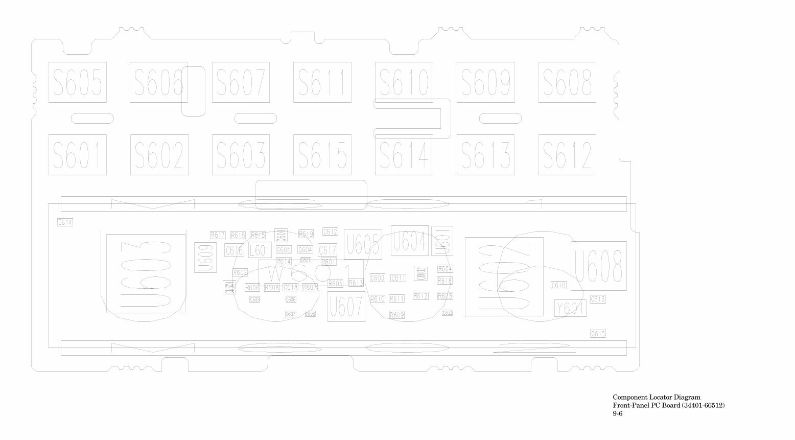
Component Locator DiagramFront-Panel PC Board (34401-66512)9-6
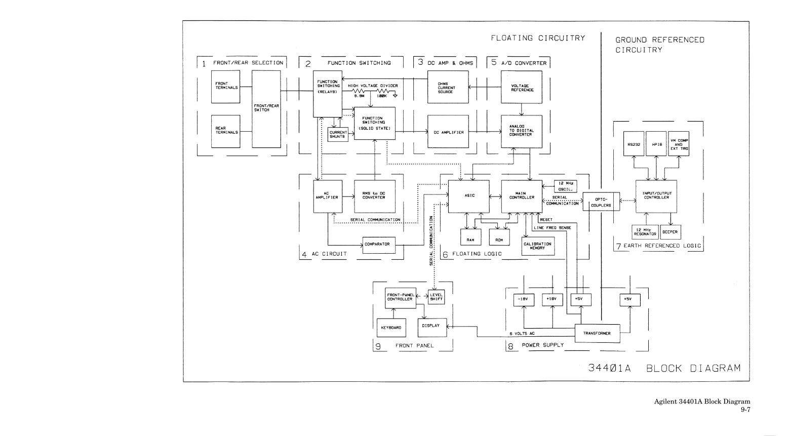
Agilent 34401A Block Diagram9-7
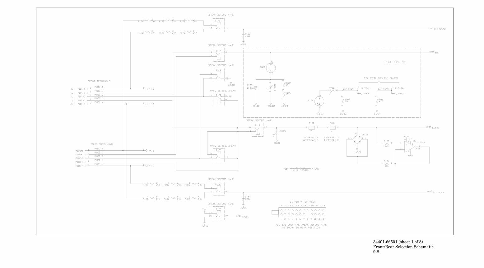
34401-66501 (sheet 1 of 8)Front/Rear Selection Schematic9-8
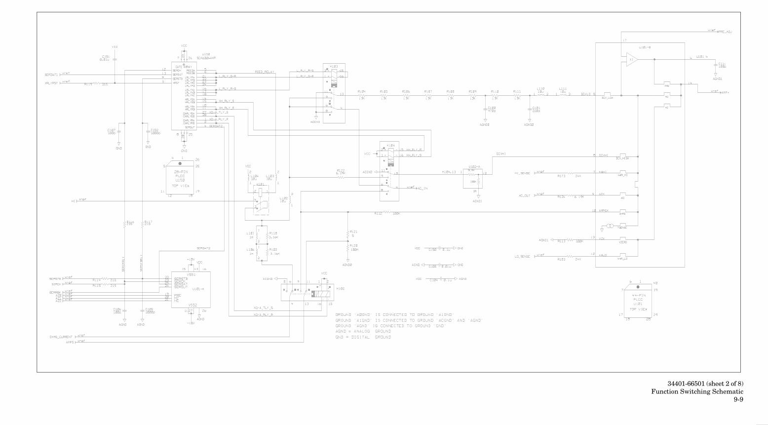
34401-66501 (sheet 2 of 8)Function Switching Schematic
9-9
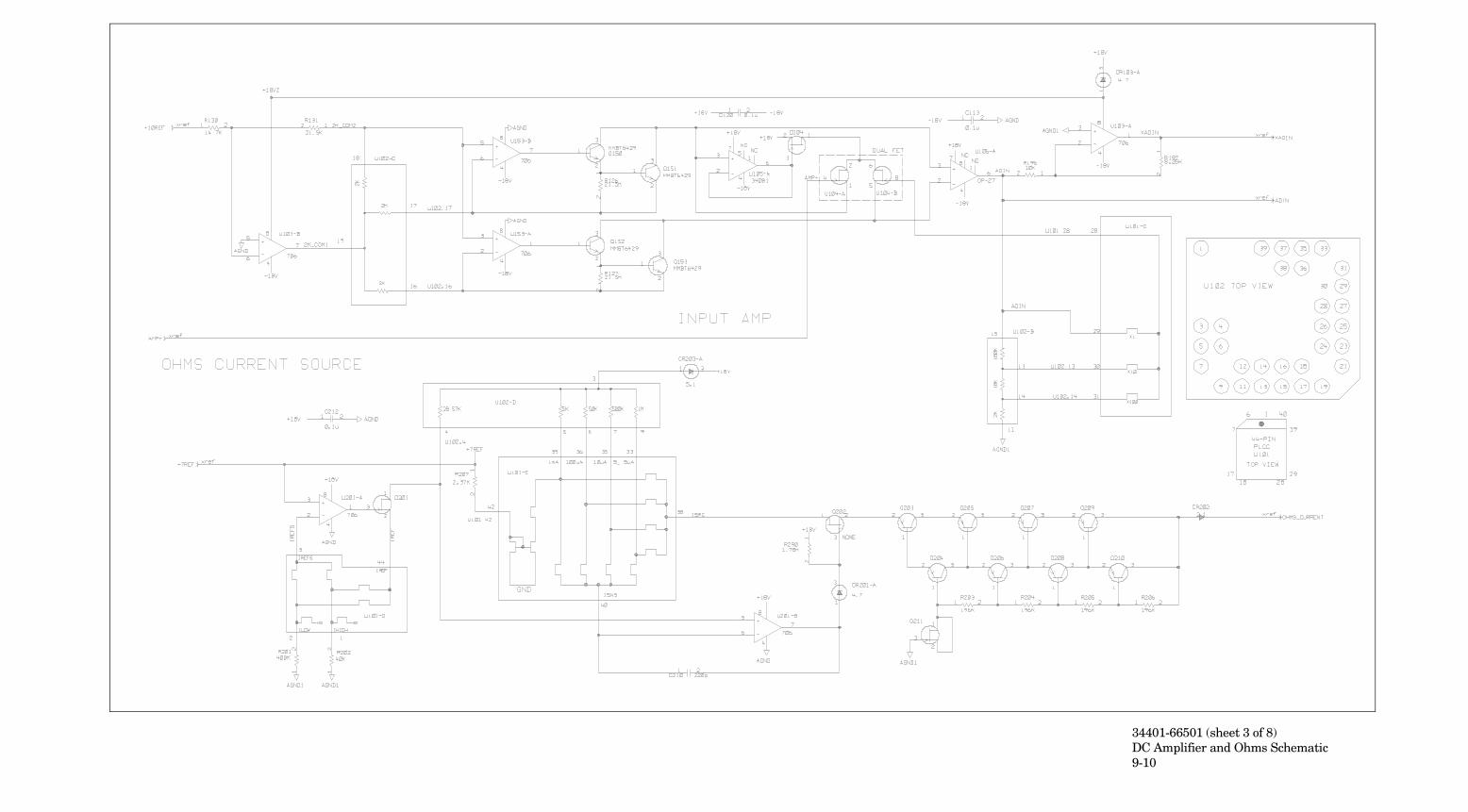
34401-66501 (sheet 3 of 8)DC Amplifier and Ohms Schematic9-10
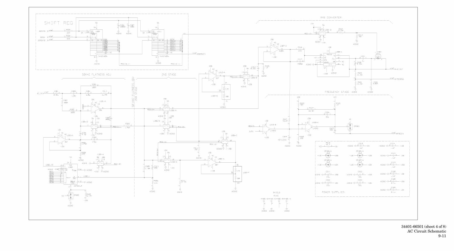
34401-66501 (sheet 4 of 8)AC Circuit Schematic
9-11
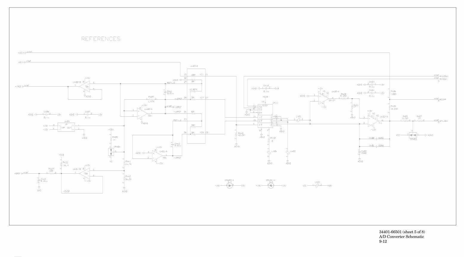
34401-66501 (sheet 5 of 8)A/D Converter Schematic9-12
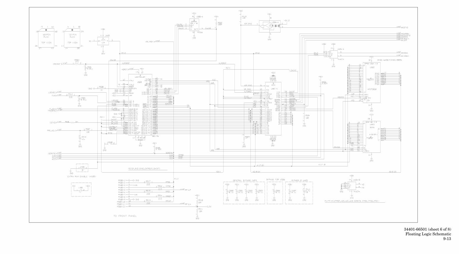
34401-66501 (sheet 6 of 8)Floating Logic Schematic
9-13
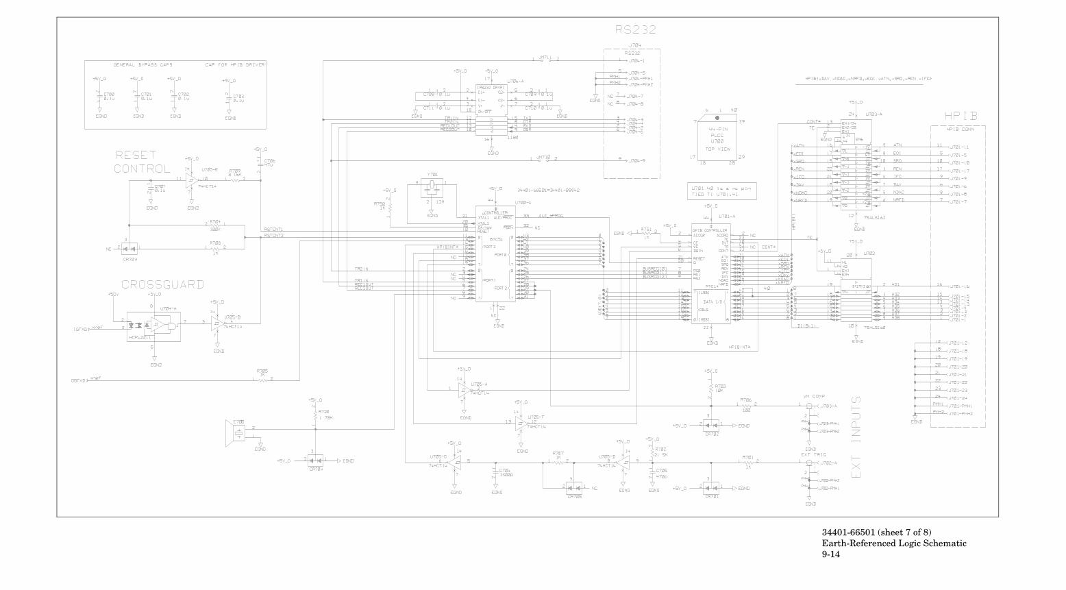
34401-66501 (sheet 7 of 8)Earth-Referenced Logic Schematic9-14
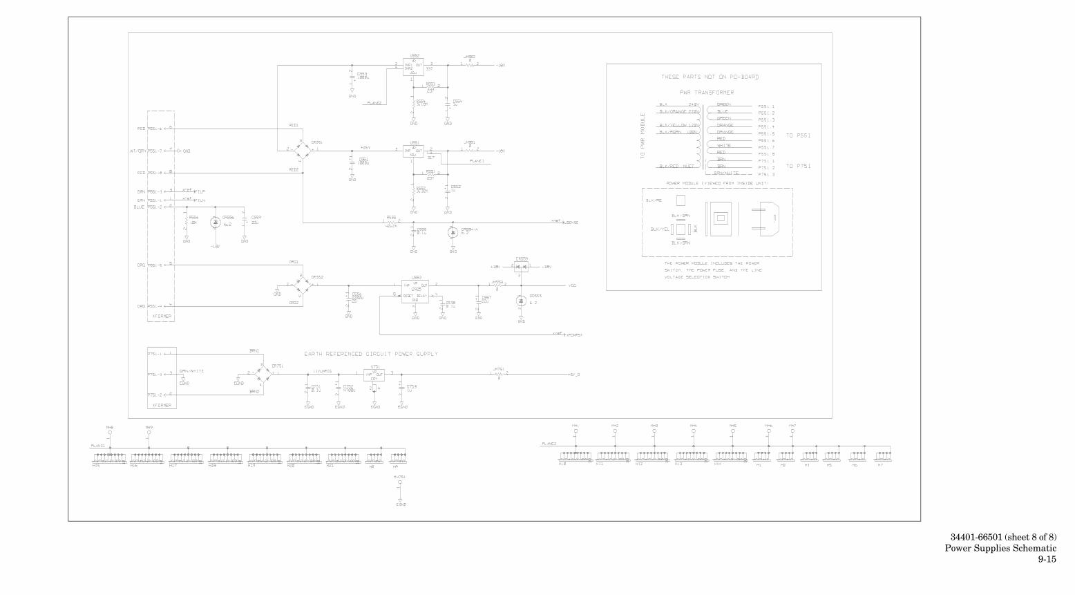
34401-66501 (sheet 8 of 8)Power Supplies Schematic
9-15
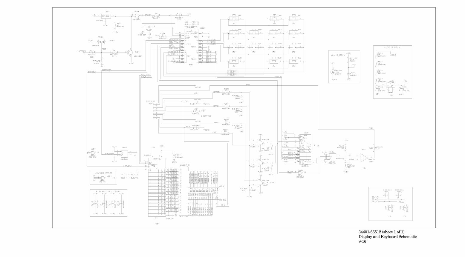
34401-66512 (sheet 1 of 1)Display and Keyboard Schematic9-16

This information is subject to change without notice.© Keysight Technologies 1991 - 2014
Edition 9, August 2014
*34401-90013*34401-90013
www.keysight.com