Keysight 16454A Magnetic Material Test...
35
Operation and Service Manual Keysight 16454A Magnetic Material Test Fixture
Transcript of Keysight 16454A Magnetic Material Test...

Operation and Service Manual
Keysight 16454A Magnetic Material Test Fixture

Notices
© Keysight Technologies 1993-2017
No part of this manual may be reproduced in any form or by any means (including electronic storage and retrieval or translation into a foreign language) without prior agreement and written consent from Keysight Technologies, Inc. as governed by United States and international copyright laws.
Trademark Acknowledgments
Manual Part Number
16454-90020
Edition
Edition 6, September 2017
Printed in Malaysia
Published by:
Keysight Technologies International Japan G.K,1-3-3 Higashikawasaki-choChuo-ku Kobe-shi, Hyogo, Japan
Warranty
THE MATERIAL CONTAINED IN THIS DOCUMENT IS PROVIDED “AS IS,” AND IS SUBJECT TO BEING CHANGED, WITHOUT NOTICE, IN FUTURE EDITIONS. FURTHER, TO THE MAXIMUM EXTENT PERMITTED BY APPLICABLE LAW, KEYSIGHT DISCLAIMS ALL WARRANTIES, EITHER EXPRESS OR IMPLIED WITH REGARD TO THIS MANUAL AND ANY INFORMATION CONTAINED HEREIN, INCLUDING BUT NOT LIMITED TO THE IMPLIED WARRANTIES OF MERCHANTABILITY AND FITNESS FOR A PARTICULAR PURPOSE. KEYSIGHT SHALL NOT BE LIABLE FOR ERRORS OR FOR INCIDENTAL OR CONSEQUENTIAL DAMAGES IN CONNECTION WITH THE FURNISHING, USE, OR PERFORMANCE OF THIS DOCUMENT OR ANY INFORMATION CONTAINED HEREIN. SHOULD KEYSIGHT AND THE USER HAVE A SEPARATE WRITTEN AGREEMENT WITH WARRANTY TERMS
COVERING THE MATERIAL IN THIS DOCUMENT THAT CONFLICT WITH THESE TERMS, THE WARRANTY TERMS IN THE SEPARATE AGREEMENT WILL CONTROL.
Technology Licenses
The hardware and/or software described in this document are furnished under a license and may be used or copied only in accordance with the terms of such license.
Declaration of Conformity
Declarations of Conformity for this product and for other Keysight products may be downloaded from the Web. Go to http://www.keysight.com/go/conformity. You can then search by product number to find the latest Declaration of Conformity.
U.S. Government Rights
The Software is “commercial computer software,” as defined by Federal Acquisition Regulation (“FAR”) 2.101. Pursuant to FAR 12.212 and 27.405-3 and Department of Defense FAR Supplement (“DFARS”) 227.7202, the U.S. government acquires commercial computer software under the same terms by which the software is customarily provided to the public. Accordingly, Keysight provides the Software to U.S. government customers under its standard commercial license, which is embodied in its End User License Agreement (EULA), a copy of which can be found at http://www.keysight.com/find/sweulaThe license set forth in the EULA represents the exclusive authority by which the U.S. government may use, modify, distribute, or disclose the Software. The EULA and the license set forth therein, does not require or permit, among other things, that Keysight: (1) Furnish technical information related to commercial computer software or commercial computer software documentation that is not customarily provided to the public; or (2) Relinquish to, or otherwise provide, the government rights in excess of these rights customarily provided to the public to use, modify, reproduce, release,
perform, display, or disclose commercial computer software or commercial computer software documentation. No additional government requirements beyond those set forth in the EULA shall apply, except to the extent that those terms, rights, or licenses are explicitly required from all providers of commercial computer software pursuant to the FAR and the DFARS and are set forth specifically in writing elsewhere in the EULA. Keysight shall be under no obligation to update, revise or otherwise modify the Software. With respect to any technical data as defined by FAR 2.101, pursuant to FAR 12.211 and 27.404.2 and DFARS 227.7102, the U.S. government acquires no greater than Limited Rights as defined in FAR 27.401 or DFAR 227.7103-5 (c), as applicable in any technical data.
Safety Notices
A CAUTION notice denotes a hazard. It calls attention to an operating procedure, practice, or the like that, if not correctly performed or adhered to, could result in damage to the product or loss of important data. Do not proceed beyond a CAUTION notice until the indicated conditions are fully understood and met.
A WARNING notice denotes a hazard. It calls attention to an operating procedure, practice, or the like that, if not correctly performed or adhered to, could result in personal injury or death. Do not proceed beyond a WARNING notice until the indicated conditions are fully understood and met.
Contents
Keysight 16454A Magnetic Material Test Fixture 3
Table of Contents
1. General Information
Introduction . . . . . . . . . . . . . . . . . . . . . . . . . . . . . . . . . . . . . . . . . . . . . . . . . . . . . . . . . . . . . . . . 5
Product Description . . . . . . . . . . . . . . . . . . . . . . . . . . . . . . . . . . . . . . . . . . . . . . . . . . . . . . . . . . 5
Specifications . . . . . . . . . . . . . . . . . . . . . . . . . . . . . . . . . . . . . . . . . . . . . . . . . . . . . . . . . . . . . . . 6
Supplemental Performance Characteristics . . . . . . . . . . . . . . . . . . . . . . . . . . . . . . . . . . . . . . . 8Typical Measurement Accuracy . . . . . . . . . . . . . . . . . . . . . . . . . . . . . . . . . . . . . . . . . . . . . . 8
2. Initial Inspection
Introduction . . . . . . . . . . . . . . . . . . . . . . . . . . . . . . . . . . . . . . . . . . . . . . . . . . . . . . . . . . . . . . . 15
Initial Inspection . . . . . . . . . . . . . . . . . . . . . . . . . . . . . . . . . . . . . . . . . . . . . . . . . . . . . . . . . . . . 15
Repackaging the Test Fixture For Shipment . . . . . . . . . . . . . . . . . . . . . . . . . . . . . . . . . . . . . . 17
3. Theory on Material Measurement
Magnetic Material Measurement . . . . . . . . . . . . . . . . . . . . . . . . . . . . . . . . . . . . . . . . . . . . . . . 19Permeability Definition . . . . . . . . . . . . . . . . . . . . . . . . . . . . . . . . . . . . . . . . . . . . . . . . . . . . 19Measurement Principle of Magnetic Material . . . . . . . . . . . . . . . . . . . . . . . . . . . . . . . . . . 20Structure of 16454A Test Fixture . . . . . . . . . . . . . . . . . . . . . . . . . . . . . . . . . . . . . . . . . . . . 23
4. Operation
Connecting the Test Fixture . . . . . . . . . . . . . . . . . . . . . . . . . . . . . . . . . . . . . . . . . . . . . . . . . . . 25Selecting Fixture and Holder . . . . . . . . . . . . . . . . . . . . . . . . . . . . . . . . . . . . . . . . . . . . . . . 25Connecting the Test Fixture to the Test Head. . . . . . . . . . . . . . . . . . . . . . . . . . . . . . . . . . 26Performing SHORT Compensation . . . . . . . . . . . . . . . . . . . . . . . . . . . . . . . . . . . . . . . . . . 28Placing the MUT into the Test Fixture . . . . . . . . . . . . . . . . . . . . . . . . . . . . . . . . . . . . . . . . 29
5. Service
Introduction . . . . . . . . . . . . . . . . . . . . . . . . . . . . . . . . . . . . . . . . . . . . . . . . . . . . . . . . . . . . . . . 31
Replaceable Parts. . . . . . . . . . . . . . . . . . . . . . . . . . . . . . . . . . . . . . . . . . . . . . . . . . . . . . . . . . . 31
Functional Test . . . . . . . . . . . . . . . . . . . . . . . . . . . . . . . . . . . . . . . . . . . . . . . . . . . . . . . . . . . . . 34Fixture Impedance Check. . . . . . . . . . . . . . . . . . . . . . . . . . . . . . . . . . . . . . . . . . . . . . . . . . 34

4 Keysight 16454A Magnetic Material Test Fixture
Contents

5
Keysight 16454A Magnetic Material Test Fixture
Operation and Service Manual
1 General Information
IntroductionThis manual contains the following information:
• The specifications of the 16454A (in this chapter).
• Initial inspection of the 16454A (see Chapter 2).
• Ordering replaceable parts for the 16454A (see Chapter 5). For measurement procedures using the 16454A, see the applicable impedance analyzer manual/help.
Product DescriptionThe 16454A is used to measure the permeability of a toroidal core.

6 Keysight 16454A Magnetic Material Test Fixture
General InformationSpecifications
1-
SpecificationsThis section lists the complete 16454A specifications.These specifications are the performance standards and limits against which the 16454A is tested. When shipped from the factory, the 16454A meets the following listed specifications.
Supplemental characteristics are intended to provide information that is useful in applying the instrument by giving non warranted performance parameters. These are denoted as typical, typically, nominal or approximate.
Applicable MUT (Material Under Test) Size See Table 1-1
Maximum DC Bias Current ±500mA
Frequency Range 1kHz to 1.0GHz typically
Operating Temperature -55˚C to +200˚C
Operating Humid ity (@wet bulb temperature <40˚C)
Up to 95% RH
Non-operating Temperature -55˚C to +200˚C
Non-operating Humid ity (@wet bulb temperature <65˚C)
Up to 90% RH
Weight
(Large Test Fixture) 140g typically
(Small Test Fixture) 120g typically
Dimension
(Large Test Fixture) ϕ30mm x 35mm H typically
(Small Test Fixture) ϕ24mm x 30mm H typically
Table 1-1 Applicable MUT Size
Fixture Small Large
Holder A B C D
b ≥ϕ3.1mm ≥ϕ3.1mm ≥ϕ6mm ≥ϕ5mm
c ≤ ϕ8mm ≤ ϕ6mm ≤ ϕ20mm ≤ ϕ20mm
h ≤ 3mm ≤ 3mm ≤ 8.5mm ≤ 8.5mm

Keysight 16454A Magnetic Material Test Fixture 7
General InformationSpecifications
Applicable Instruments
E4990A + 42942A (Option E4990A-120 is required)
E4991B with Option E4991B-002

8 Keysight 16454A Magnetic Material Test Fixture
General InformationSupplemental Performance Characteristics
1-
Supplemental Performance CharacteristicsThis section shows supplemental performance characteristics data. This supplemental performance characteristics is not specification.
Typical Measurement Accuracy
@ tan δ < 0.1
Loss Tangent Accuracy of
'r Accuracy'rm'rm
------------
f < 1MHz...................................................................[%] Typical
f ≥ 1MHz..................................[%] Typical
4 25F'rm---------- 0.1
F'rm f------------ + +
4 25F'rm---------- F'rm 1 15
F'rm----------+
2f2+ +
@ tan δ < 0.1.................................................................... (Typical)
f < 1MHz
...............................................................................(Typical)
........................................................................................(Typical)
f ≥ 1MHz
...............................................................(Typical)
......................................................................................(Typical)
· r tan
Ea Eb+
Ea 0.002 0.001F'rm f------------+=
Eb
'rm'rm
----------- tan100---------=
Ea 0.002 0.001F'rm f------------ 0.004f+ +=
Eb
'rm'rm
----------- tan100---------=

Keysight 16454A Magnetic Material Test Fixture 9
General InformationSupplemental Performance Characteristics
Where,
f is measurement frequency [GHz]
F [mm]
h is the height of MUT [mm]
b is the inner diameter of MUT
c is the outer diameter of MUT
tan δ is the measured value of loss tangent
μrm’ is the measured value of permeability
Cond itions of accuracy characteristics
• Use the Low Z Test Head for permeability measurement
• OPEN/SHORT/50Ω calibration must be done. Calibration ON.
• Averaging (on point) factor is larger than 32 at which calibration is done if Cal points is set to USER DEF.
• Measurement points are same as the calibration points if Cal point is set to USER DEF.
• Environment temperature is within ±5ºC of temperature at which calibration is done, and within 13ºC to 33ºC. Beyond this environmental temperature condition, accuracy is twice as bad as specified.
h cb--ln=

10 Keysight 16454A Magnetic Material Test Fixture
General InformationSupplemental Performance Characteristics
1-
Figure 1-1 Typical Permeability Measurement Accuracy (@F1=0.5)
Figure 1-2 Typical Permeability Measurement Accuracy (@F1=3)
1. F h= cb--ln
Keysight 16454A Magnetic Material Test Fixture 11
General InformationSupplemental Performance Characteristics
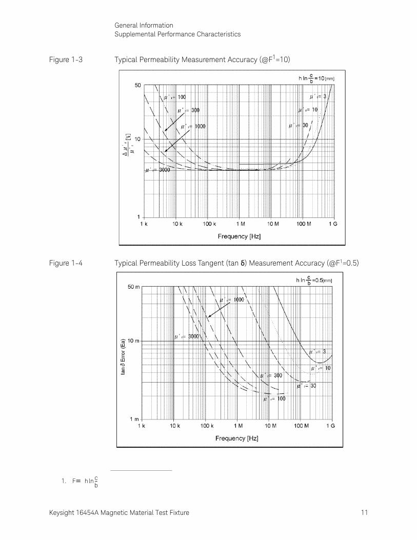
Figure 1-3 Typical Permeability Measurement Accuracy (@F1=10)
Figure 1-4 Typical Permeability Loss Tangent (tan δ) Measurement Accuracy (@F1=0.5)
1. F h= cb--ln

12 Keysight 16454A Magnetic Material Test Fixture
General InformationSupplemental Performance Characteristics
1-
Figure 1-5 Typical Permeability Loss Tangent (tan δ) Measurement Accuracy (@F1=3)
Figure 1-6 Typical Permeability Loss Tangent (tan δ) Measurement Accuracy (@F1=10)
1. F h= cb--ln

Keysight 16454A Magnetic Material Test Fixture 13
General InformationSupplemental Performance Characteristics
Figure 1-7 Typical Permeability Measurement Accuracy (μr v.s. Frequency, @F1=0.5)
Figure 1-8 Typical Permeability Measurement Accuracy (μr v.s. Frequency, @F1=3)
1. F h= cb--ln

14 Keysight 16454A Magnetic Material Test Fixture
General InformationSupplemental Performance Characteristics
1-
Figure 1-9 Typical Permeability Measurement Accuracy (μr v.s. Frequency, @F1=10)
1. F h= cb--ln

15
Keysight 16454A Magnetic Material Test Fixture
Operation and Service Manual
2 Initial Inspection
IntroductionThis chapter contains the following information:
• Initial inspection.
• Repackaging the test fixture for shipment.
Initial InspectionThe magnetic material test fixture has been carefully inspected before being shipped from the factory. It should be in perfect physical condition, no scratches, dents or the like. It should also be in perfect electrical condition. Verify this by carefully performing an incoming inspection to check the magnetic material test fixture set for signs of physical damage and missing contents. If any discrepancy is found, notify the carrier and Keysight Technologies. Your Keysight Technologies sales office will arrange for repair and replacement without waiting for the claim to be settled.
• Inspect the shipping container for damage. Keep the shipping materials until the inspection is completed.
• Verify that the shipping container contains everything listed in Table 2-1.
• Inspect the exterior of the 16454A for any signs of damage.

16 Keysight 16454A Magnetic Material Test Fixture
Initial InspectionInitial Inspection
2-
Table 2-1 16454A Contents
Ref/D
Part Number Qty Description RoHS Compliant
Replacement Part
Qty
1 8710-2081 1 Tweezers 8710-2081 1
2 16454-00601 1 Fixture Holder 16454-00601 1
3 0515-1050 2 Screw, Hex Recess 0515-1050 2
4 (not assigned) 1 Test Fixture (Large) (not assigned) 1
5 (not assigned) 1 Test Fixture (Small) (not assigned) 1
6 16454-25002 1 Holder A 16454-25002 1
7 16454-25001 1 Holder B 16454-25001 1
8 16454-25004 1 Holder C (WITHOUT HOLE) 16454-25004 1
9 16454-25003 1 Holder D (WITH HOLE) 16454-25003 1
10 1540-0622 1 Holder Case 9300-2603 1
11 5188-4452 1 Hex Key, 2.5mm Across Flats 5188-4452 1
- 16454-60101 1 Carrying Case1 16454-60101 1
- 16454-90020 1 Operation and Service Manual12 16454-90020 1
1. These parts are not shown in this figure.2. Only available for option ABA.

Keysight 16454A Magnetic Material Test Fixture 17
Initial InspectionRepackaging the Test Fixture For Shipment
Repackaging the Test Fixture For ShipmentIf shipment to a Keysight Technologies service center is required, each test fixture should be repackaged using the original factory packaging materials.
If this material is not available, comparable packaging materials may be used. Wrap the magnetic material test fixture in heavy paper and pack in anti-static plastic packing material.Use sufficient shock absorbing material on all sides of the 16454A to provide a thick, firm cushion and to prevent movement. Seal the shipping container securely and mark it FRAGILE.

18 Keysight 16454A Magnetic Material Test Fixture
Initial InspectionRepackaging the Test Fixture For Shipment
2-
19
Keysight 16454A Magnetic Material Test Fixture
Operation and Service Manual
3 Theory on Material Measurement
This chapter explains the basic principle and the concept of material measurement.
Magnetic Material Measurement
Permeability Definition
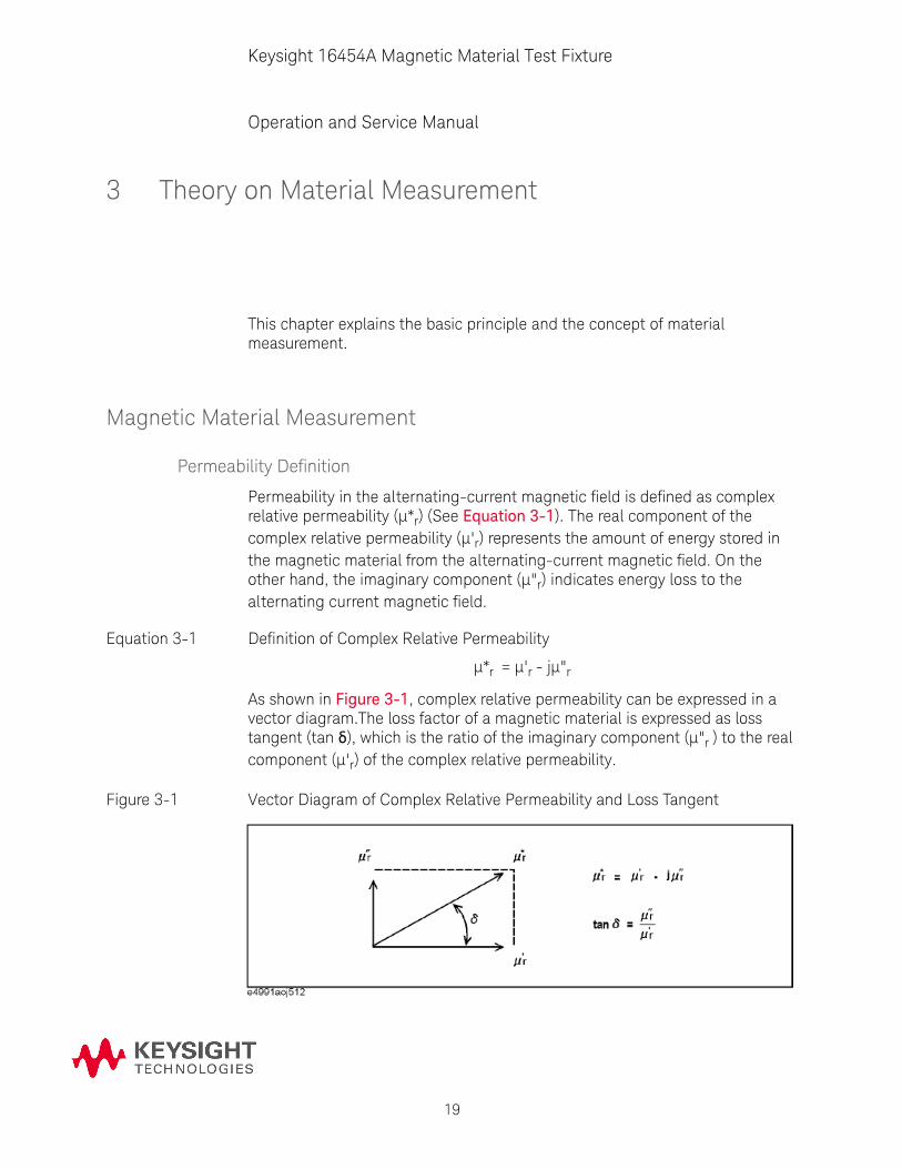
Permeability in the alternating-current magnetic field is defined as complex relative permeability (μ*r) (See Equation 3-1). The real component of the complex relative permeability (μ'r) represents the amount of energy stored in the magnetic material from the alternating-current magnetic field. On the other hand, the imaginary component (μ"r) indicates energy loss to the alternating current magnetic field.
Equation 3-1 Definition of Complex Relative Permeability
μ*r = μ'r - jμ"r
As shown in Figure 3-1, complex relative permeability can be expressed in a vector diagram.The loss factor of a magnetic material is expressed as loss tangent (tan δ), which is the ratio of the imaginary component (μ"r ) to the real component (μ'r) of the complex relative permeability.
Figure 3-1 Vector Diagram of Complex Relative Permeability and Loss Tangent

20 Keysight 16454A Magnetic Material Test Fixture
Theory on Material MeasurementMagnetic Material Measurement
3-
Measurement Principle of Magnetic Material
When using a LCR meter or an Impedance Analyzer, the inductance measurement method is employed to measure complex relative permeability. In this method, a DUT (toroidal core) is coiled with a wire and relative permeability is calculated from the measured inductance values. This section explains the measurement principle when using the test fixture, 16454A.
Figure 3-2 Relationship among Current, Magnetic Flux, and Magnetic Flux Density
Generally, the magnetic flux density (B) induced by the current flowing in an infinitely long straight wire shown in (a) of Figure 3-2 is expressed as Equation 3-2.
Equation 3-2 Magnetic Flux Density Induced by Current Flowing in an Infinitely Long Straight Wire
On the other hand, the magnetic flux ( ) induced by current flowing in the closed loop shown in (b) of Figure 3-2 is expressed as Equation 3-3. Note that L indicates the self-inductance of the closed loop.
Equation 3-3 Magnetic Flux Induced by Current in Closed Loop
Furthermore, this magnetic flux ( ) also can be expressed by integrating the magnetic flux density (B) throughout the enclosed surface, as shown in Figure 3-2 (See Equation 3-4).
Equation 3-4 Relationship between Magnetic Flux and Magnetic Flux Density
When a DUT (toroidal core) is mounted in 16454A, an ideal (no magnetic flux leakage) one turn inductor is formed, as shown in Figure 3-3.
B I2r-------=
LI=
B sd=

Keysight 16454A Magnetic Material Test Fixture 21
Theory on Material MeasurementMagnetic Material Measurement
Figure 3-3 Measurement Principle When Using 16454A Test Fixture
The self-inductance of the measurement circuit including the DUT is derived as Equation 3-5 fromEquation 3-2, Equation 3-3, Equation 3-4, and the physical shape of 16454A.
Equation 3-5 Self-Inductance of Measurement Circuit
By unfolding Equation 3-5 with μ0 as permeability of free space and μr as relative permeability of the DUT, Equation 3-6 can be obtained.
Equation 3-6 Self Inductance of Measurement Circuit
By further unfolding Equation 3-6, Equation 3-7can be obtained.
Equation 3-7 Self Inductance of Measurement Circuit
By transforming Equation 3-7 to calculate the relative permeability (μr) of the DUT, Equation 3-8 can be obtained.
Equation 3-8 Relative Permeability of DUT
L 1I-- B s
2r------- rd zd
0
h0
a
e
=d=
L0
2r------- rd zd
0
h0
c2--
e
0r
2r-------- rd zd
0
h0
b2--
c2--
0
2r------- rd zd
h
h0
b2--
c2--
0
2r------- rd zd
0
h0
a
b2--
+ + +=
L0
2----- r 1– h c
b-- h0+ln e
a--ln
=
r
2 L Lss–
0h cb--ln
--------------------- 1+=

22 Keysight 16454A Magnetic Material Test Fixture
Theory on Material MeasurementMagnetic Material Measurement
3-
Lss in Equation 3-9 indicates the self-inductance when a DUT is not mounted in the test fixture.
Equation 3-9 Self-Inductance When DUT Is Not Mounted in Test Fixture
Figure 3-4 Loss of Magnetic Material
The impedance Z of the circuit (i) in Figure 3-4 is expressed as Equation 3-10, and the complex impedance Z* of the circuit (ii) is expressed as Equation 3-11.
Equation 3-10 Impedance of Circuit (i)
Equation 3-11 Complex Impedance of Circuit (ii)
As alternating current causes inductance loss, the self-inductance L of the measurement circuit is expressed as complex impedance, as shown in Equation 3-12.
Equation 3-12 Self-Inductance of Measurement Circuit Expressed as Complex Impedance
Substituting “L” from Equation 3-12 to Equation 3-8 yields Equation 3-13.
Equation 3-13 Complex Relative Permeability of DUT
Lss
0
2-----h0
ea--ln=
Z jL=
Z Rs jLs+ jRsj----- Ls+ = =
L Zj----=
r2 Z jLss–
j0h cb--ln
----------------------------- 1+=

Keysight 16454A Magnetic Material Test Fixture 23
Theory on Material MeasurementMagnetic Material Measurement
Structure of 16454A Test Fixture
As shown inFigure 3-5, 16454A has a residual impedance Z*res.
Figure 3-5 16454A Residual Impedance
Given the ideal impedance Z*ss of the 16454A text fixture with no DUT mounted, the residual impedance Z*res can be calculated from the measured impedance Z*sm with no DUT mounted in 16454A (in SHORT state).
Equation 3-14 16454A Residual Impedance
Errors due to residual impedance can be minimized by SHORT compensation. The impedance after error compensation Z*comp can be calculated from the measured impedance Z*m with a DUT mounted in 16454A, as shown in Equation 3-15.
Equation 3-15 Compensated Impedance
Assuming that Z*ss consists only of inductance elements ( ), the complex relative permeability of the DUT can be calculated using Equation 3-13 and compensated impedance, Z*comp = Z*, as shown in Equation 3-16.
Equation 3-16 Complex Permeability of DUT
Zres Zsm Zss–=
Zcomp Zm Zres–=
Zss jLss=
r2 Zm Zsm–
j0h cb--ln
------------------------------- 1+=

24 Keysight 16454A Magnetic Material Test Fixture
Theory on Material MeasurementMagnetic Material Measurement
3-

25
Keysight 16454A Magnetic Material Test Fixture
Operation and Service Manual
4 Operation
Connecting the Test Fixture
Selecting Fixture and Holder
The 16454A consists of two fixtures, a large one and a small one. The applicable MUT size for each fixture is listed in Table 4-1.
Figure 4-1 shows the dimensions of the MUT holder.
Figure 4-1 Dimensions of the MUT Holder
Table 4-1 MUT Size for Test Fixtures
Fixture Small Large
Holder A B C D
MUT Outer Diameter (mm) ≤ ϕ8mm ≤ ϕ6mm ≤ ϕ20mm ≤ ϕ20mm
MUT Inner Diameter (mm) ≥ ϕ3.1mm ≥ ϕ3.1mm ≥ ϕ6mm ≥ ϕ5mm
MUT Height (mm) ≤ 3mm ≤ 3mm ≤ 8.5mm ≤ 8.5mm

26 Keysight 16454A Magnetic Material Test Fixture
OperationConnecting the Test Fixture
4-
Connecting the Test Fixture to the Test Head
To connect your fixture to the Test Head, perform the following steps:
1. Turn the APC-7 connector on the test head as shown in Figure 4-2.
2. Verify that the connector sleeve is retracted fully as shown in Figure 4-3.
Figure 4-2
Figure 4-3
3. Secure the test fixture to the fixture holder using the two screws.
4. Connect the connector on the underside of the test fixture to the APC-7 connector on the test head.
5. Secure the fixture holder to the test station using the two screws.
R

Keysight 16454A Magnetic Material Test Fixture 27
OperationConnecting the Test Fixture
Figure 4-4 Connecting the Test Fixtures (16454A Small)

28 Keysight 16454A Magnetic Material Test Fixture
OperationConnecting the Test Fixture
4-
Performing SHORT Compensation
The SHORT Compensation corrects for the residual impedance due to the test fixture.
1. Remove the cap of the fixture.
2. Place a MUT holder only in the fixture.
3. Replace the cap by screwing tightly.

Keysight 16454A Magnetic Material Test Fixture 29
OperationConnecting the Test Fixture
Placing the MUT into the Test Fixture
How to place the MUT on the 16454A is shown below:
1. Remove the cap of the fixture.
2. Place a MUT onto the MUT holder and insert it into the fixture.
3. Replace the cap by screwing tightly.

30 Keysight 16454A Magnetic Material Test Fixture
OperationConnecting the Test Fixture
4-

31
Keysight 16454A Magnetic Material Test Fixture
Operation and Service Manual
5 Service
IntroductionThis chapter gives the service information for the 16454A Magnetic Material Test Fixture.
Serial Number for Non-RoHS 16454A: “MY43100001 – MY43200586” / “SG43100001 – SG43200586”
Serial Number for RoHS 16454A: “MY43200587/SG43200587 and above”
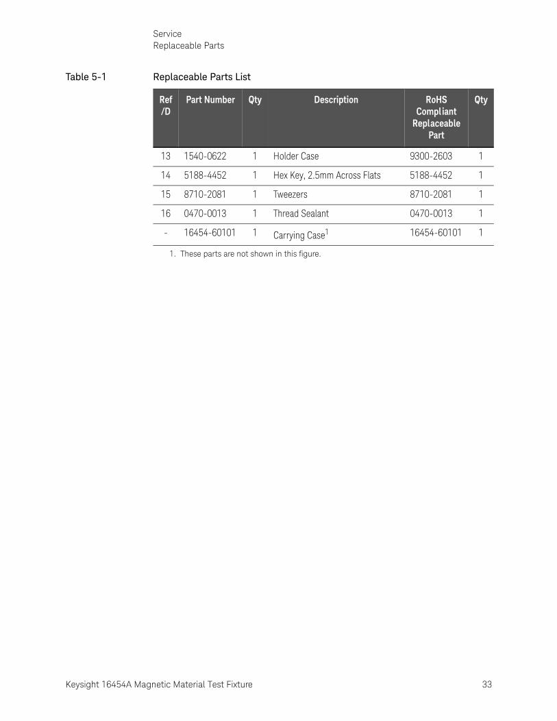
Replaceable PartsTable 5-1 identify the supported parts and their respective RoHS compliant replacement support part. Due to limited availability of RoHS compliance station and technical difficulties in RoHS soldering, only parts and support level that do not require RoHS soldering are supported. Replace all defective parts with RoHS compliance part number. The parts listed in this table can be ordered from your nearest Keysight Technologies office. Ordering information should include the Keysight part number and the quantity required.

32 Keysight 16454A Magnetic Material Test Fixture
ServiceReplaceable Parts
5-
Table 5-1 Replaceable Parts List
Ref/D
Part Number Qty Description RoHS Compliant
Replaceable Part
Qty
1 16454-00601 1 Length Positioning Stage Assembly
16454-00601 1
2 0515-1050 2 Screw, Hex Recess 0515-1050 2
3 16454-23004 1 Fixture Flange (Large) 16454-23004 1
4 1250-0816 2 Conn-RF Conn 1250-0816 2
5 16454-23005 1 Center Pin 16454-23005 1
6 16454-23003 1 Fixture Cap (Large) 16454-23003 1
7 16454-23002 1 Fixture Flange (Small) 16454-23002 1
8 16454-23001 1 Fixture Cap (Small) 16454-23001 1
9 16454-25002 1 Holder A 16454-25002 1
10 16454-25001 1 Holder B 16454-25001 1
11 16454-25004 1 Holder C (WITHOUT HOLE) 16454-25004 1
12 16454-25003 1 Holder D (WITH HOLE) 16454-25003 1
Keysight 16454A Magnetic Material Test Fixture 33
ServiceReplaceable Parts
13 1540-0622 1 Holder Case 9300-2603 1
14 5188-4452 1 Hex Key, 2.5mm Across Flats 5188-4452 1
15 8710-2081 1 Tweezers 8710-2081 1
16 0470-0013 1 Thread Sealant 0470-0013 1
- 16454-60101 1 Carrying Case1 16454-60101 1
1. These parts are not shown in this figure.
Table 5-1 Replaceable Parts List
Ref/D
Part Number Qty Description RoHS Compliant
Replaceable Part
Qty

34 Keysight 16454A Magnetic Material Test Fixture
ServiceFunctional Test
5-
Functional TestThis section provides the functional test procedure to check the 16454A performance. The functional test can be used for post repair function verification.
Fixture Impedance Check
1. Perform calibration at the APC-7 terminal of the measurement instrument.
2. Place the fixture (small) on the calibrated APC-7 terminal of the measurement instrument.
3.Read Ls and Rs value for each test fixture. The guideline is as follows:
R
R
Table 5-2 Fixture Impedance Check Guideline
Fixture Frequency Parameter Guidel ine
Small 100MHz Ls 1nH ± 0.5nH
Rs <100mΩ
Large 100MHz Ls 5.5nH ± 2.5nH
Rs <300mΩ

This information is subject to change without notice.
© Keysight Technologies 1993-2017
Edition 6 September 2017
*16454-90020*16454-90020www.keysight.com