KeypadLinc Dimmer 2486D - Insteon · the KeypadLinc to bare Ground wire or Ground screw in wall box...
24
Page 1 of 24 Rev: 1/21/2014 7:36 AM KeypadLinc™ Dimmer INSTEON ® 6- and 8-Button Scene Control Keypad with Dimmer Owner’s Manual, Rev 5.0+ (#2486Dxxx) 8-button KeypadLinc 6-button KeypadLinc
Transcript of KeypadLinc Dimmer 2486D - Insteon · the KeypadLinc to bare Ground wire or Ground screw in wall box...
Page 1 of 24 Rev: 1/21/2014 7:36 AM
KeypadLinc™ Dimmer INSTEON® 6- and 8-Button Scene Control Keypad with Dimmer Owner’s Manual, Rev 5.0+ (#2486Dxxx)
8-button KeypadLinc
6-button KeypadLinc
Page 2 of 24 Rev: 1/21/2014 7:36 AM
KeypadLinc – Features and Benefits ........................................................................................................ 3 Features..................................................................................................................................................... 3 What’s in the box? ..................................................................................................................................... 3
Installing KeypadLinc ................................................................................................................................. 4 Identifying the Electrical Wires in your Home ............................................................................................ 4 Tools Needed ............................................................................................................................................ 4 Button Naming ........................................................................................................................................... 4 Installation – Circuit with 1 Switch ............................................................................................................. 5 Installation – Circuit with 2 Switches ......................................................................................................... 6 Installation – Circuit with 3 (or more) Switches ......................................................................................... 7
Using KeypadLinc ....................................................................................................................................... 9 LEDs .......................................................................................................................................................... 9 Button Taps ............................................................................................................................................... 9 Button Tap / Press and Holds ................................................................................................................... 9 Local On-Level .......................................................................................................................................... 9
Setting Up INSTEON Scenes ................................................................................................................... 10 Add KeypadLinc Button to a Scene as a Controller ................................................................................ 10 Remove KeypadLinc Button from a Scene as a Controller ..................................................................... 10 Add KeypadLinc Button to a Scene as a Responder .............................................................................. 11 Remove KeypadLinc from a Scene as a Responder .............................................................................. 11 Changing Button Modes (Toggle / Non-Toggle Mode) ........................................................................... 11 LED Brightness ........................................................................................................................................ 12 Power Restore ......................................................................................................................................... 12 Add X10 Address to a Button .................................................................................................................. 12 Remove X10 Address from a Button ....................................................................................................... 12 Advanced X10 Programming................................................................................................................... 12
Advanced Features ................................................................................................................................... 13 Add Multiple Scene Responders (formerly “Multi-Linking Mode”) ........................................................... 13 Remove Multiple Scene Responders (formerly “Multi-Unlinking Mode”) ................................................ 13 Synchronized Scenes (formerly “Cross-Linking”) .................................................................................... 13 Beep on Button Tap or Press .................................................................................................................. 14 “Radio” Button Groups (only 1 LED of “N” at a time – software recommended) ..................................... 15 Air Gap..................................................................................................................................................... 16 Factory Reset .......................................................................................................................................... 16 Changing Between 6 and 8 Button Configurations ................................................................................. 17
Changing to 6-Button Configuration .................................................................................................... 17 Changing to 8-Button Configuration .................................................................................................... 17
Changing Buttons .................................................................................................................................... 18 Local-Ramp-Rate (software recommended) ........................................................................................... 18
Additional Resources ............................................................................................................................... 18 Helpful Videos ......................................................................................................................................... 18 Optional Accessories ............................................................................................................................... 19
Specifications ............................................................................................................................................ 19 Troubleshooting ........................................................................................................................................ 21 Certification and Warranty ....................................................................................................................... 24
Certification .............................................................................................................................................. 24 FCC and Industry Canada Compliance Statement ................................................................................. 24 ETL / UL Warning (Safety Warning) ........................................................................................................ 24 Limited Warranty ..................................................................................................................................... 24
Limitations ............................................................................................................................................ 24
Page 3 of 24 Rev: 1/21/2014 7:36 AM
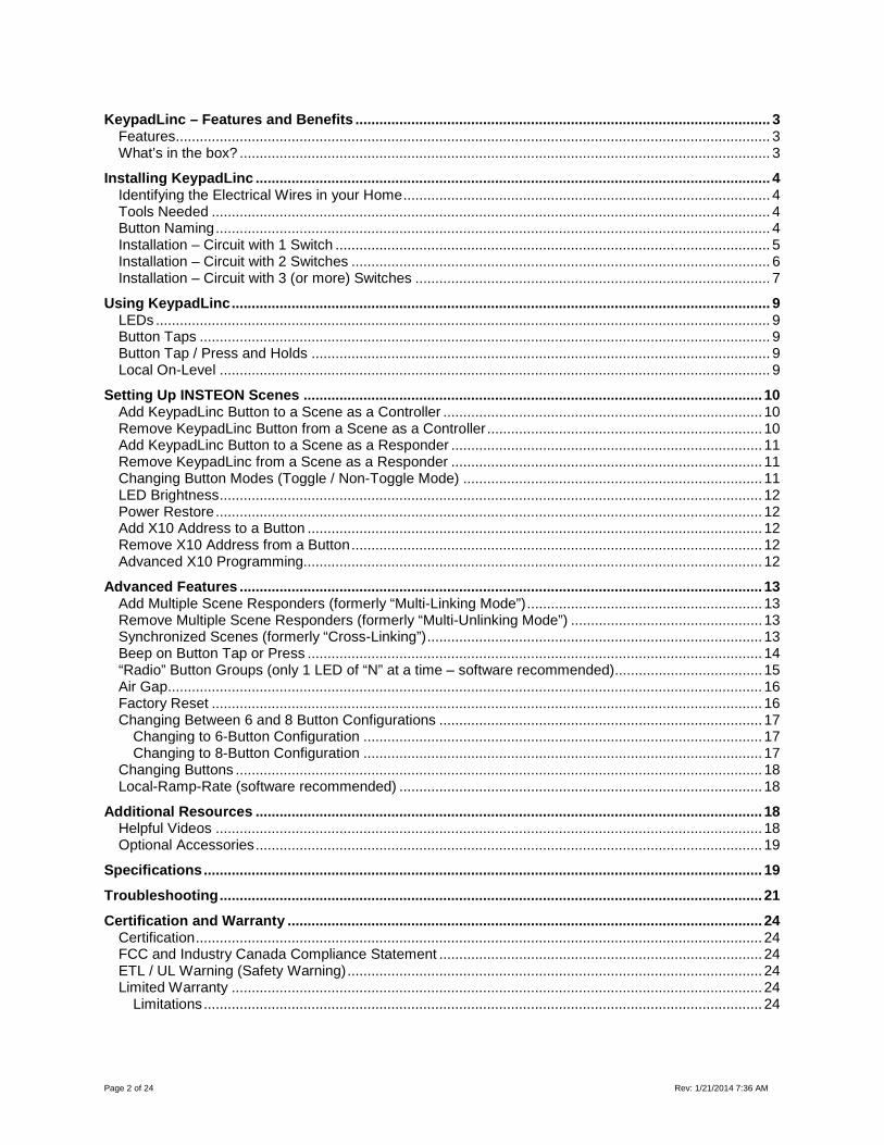
KeypadLinc – Features and Benefits Congratulations on purchasing the elegant, high-quality KeypadLinc INSTEON/X10 scene controller. This intuitive keypad controls up to 6/8 scenes and has a built-in dimmer to create dramatic whole-room changes at the tap of a button. Additionally, each button has an LED backlight that can be easily configured as a status indicator for virtually any INSTEON device/scene you wish to monitor.
Features - Easy to set up and use - Integrated dimmer (up to 600 watts) - 32 dim levels and ramp rates - Each button can be a scene controller and/or responder - Each button can control the other buttons on the keypad - Supports up to 417 scene memberships - Multiple buttons can be included in the same scene - Dual On/Off settings: toggle (default) and “always send On/Off” - Dimmable status LEDs - Beeper makes setup a breeze and can function as a chime module - Configurable to beep on each button tap or press - X10 compatible - Wires in like a standard wall switch (requires a Neutral wire) - All settings preserved in non-volatile memory through power failures - Local programming lockout available via software - 2-year warranty - Custom-etched buttons available - Can be converted between 6- and 8-button modes
What’s in the Box? - KeypadLinc Dimmer - Quick Start Guide - 2 mounting screws - 4 wire nuts
Page 4 of 24 Rev: 1/21/2014 7:36 AM
Installing KeypadLinc
CAUTIONS AND WARNINGS
Read and understand these instructions before installing and retain them for future reference.
This product is intended for installation in accordance with the National Electric Code and local regulations in the United States or the Canadian Electrical Code and local regulations in Canada. Use indoors only. This product is not designed or approved for use on power lines other than 120V 60Hz, single phase. Attempting to use this product on non-approved power lines may have hazardous consequences. Recommended installation practices: - Use only indoors or in outdoor rated box - Be sure that you have turned off the circuit breaker or removed the fuse for the circuit you are installing this product into.
Installing this product with the power on will expose you to dangerous voltages. - Connect using only copper or copper-clad wire - This product may feel warm during operation. The amount of heat generated is within approved limits and poses no
hazards. To minimize heat buildup, ensure the area surrounding the rear of this product is as clear of clutter as possible. - Each INSTEON product is assigned a unique INSTEON ID, which is printed on the product’s label. - To reduce the risk of overheating and possible damage to other equipment, do not use this product to control Loads in
excess of the specified maximum(s) or, install in locations with electricity specifications which are outside of the product’s specifications. If this device supports dimming, please note that dimming an inductive Load, such as a fan or transformer, could cause damage to the dimmer, the load bearing device, or both. If the manufacturer of the load device does not recommend dimming, use a non-dimming INSTEON on/off switch. USER ASSUMES ALL RISKS ASSOCIATED WITH DIMMING AN INDUCTIVE LOAD.
Identifying the Electrical Wires in your Home
- Line – usually Black, may also be called HOT, LIVE or Power, carries 120VAC electricity into the wall box - Neutral – usually White commonly daisy chained from box to box usually appearing as a White wire bundle - Load – usually Black from a separate cable jacket - Ground – Bare wire or metal fixture (if grounded)
IMPORTANT! If you have any difficulties or questions, consult an electrician. If you are not knowledgeable about, and comfortable with electrical circuitry, you should have a qualified electrician install the product for you.
Tools Needed • Flathead screwdriver • Phillips screwdriver • Wire cutter/stripper • Voltage meter
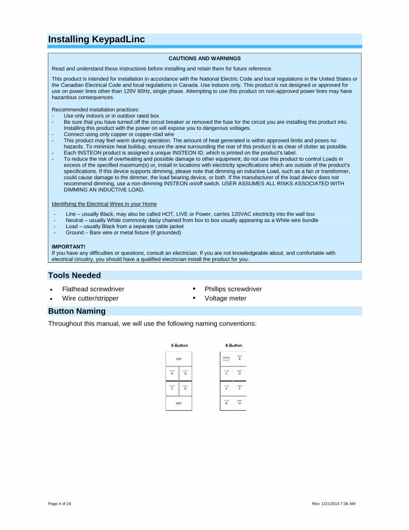
Button Naming Throughout this manual, we will use the following naming conventions:
Page 5 of 24 Rev: 1/21/2014 7:36 AM
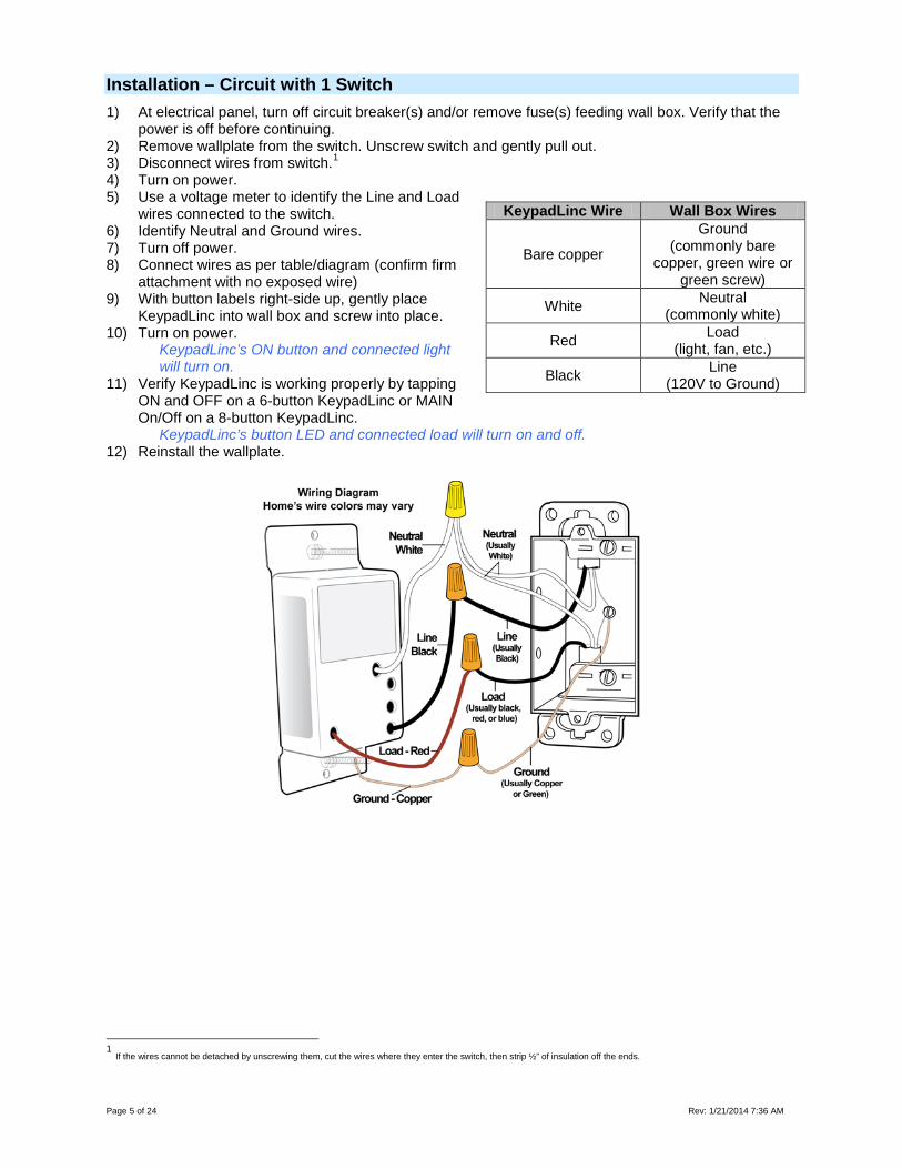
Installation – Circuit with 1 Switch 1) At electrical panel, turn off circuit breaker(s) and/or remove fuse(s) feeding wall box. Verify that the
power is off before continuing. 2) Remove wallplate from the switch. Unscrew switch and gently pull out. 3) Disconnect wires from switch.1 4) Turn on power. 5) Use a voltage meter to identify the Line and Load
wires connected to the switch. 6) Identify Neutral and Ground wires. 7) Turn off power. 8) Connect wires as per table/diagram (confirm firm
attachment with no exposed wire) 9) With button labels right-side up, gently place
KeypadLinc into wall box and screw into place. 10) Turn on power.
KeypadLinc’s ON button and connected light will turn on.
11) Verify KeypadLinc is working properly by tapping ON and OFF on a 6-button KeypadLinc or MAIN On/Off on a 8-button KeypadLinc.
KeypadLinc’s button LED and connected load will turn on and off. 12) Reinstall the wallplate.
1 If the wires cannot be detached by unscrewing them, cut the wires where they enter the switch, then strip ½” of insulation off the ends.
KeypadLinc Wire Wall Box Wires
Bare copper
Ground (commonly bare
copper, green wire or green screw)
White Neutral (commonly white)
Red Load (light, fan, etc.)
Black Line (120V to Ground)
Page 6 of 24 Rev: 1/21/2014 7:36 AM
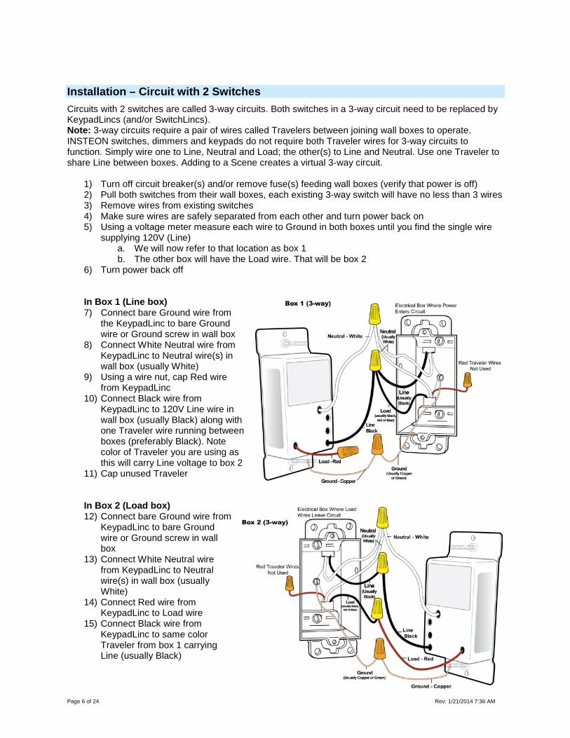
Installation – Circuit with 2 Switches Circuits with 2 switches are called 3-way circuits. Both switches in a 3-way circuit need to be replaced by KeypadLincs (and/or SwitchLincs). Note: 3-way circuits require a pair of wires called Travelers between joining wall boxes to operate. INSTEON switches, dimmers and keypads do not require both Traveler wires for 3-way circuits to function. Simply wire one to Line, Neutral and Load; the other(s) to Line and Neutral. Use one Traveler to share Line between boxes. Adding to a Scene creates a virtual 3-way circuit.
1) Turn off circuit breaker(s) and/or remove fuse(s) feeding wall boxes (verify that power is off) 2) Pull both switches from their wall boxes, each existing 3-way switch will have no less than 3 wires 3) Remove wires from existing switches 4) Make sure wires are safely separated from each other and turn power back on 5) Using a voltage meter measure each wire to Ground in both boxes until you find the single wire
supplying 120V (Line) a. We will now refer to that location as box 1 b. The other box will have the Load wire. That will be box 2
6) Turn power back off
In Box 1 (Line box) 7) Connect bare Ground wire from
the KeypadLinc to bare Ground wire or Ground screw in wall box
8) Connect White Neutral wire from KeypadLinc to Neutral wire(s) in wall box (usually White)
9) Using a wire nut, cap Red wire from KeypadLinc
10) Connect Black wire from KeypadLinc to 120V Line wire in wall box (usually Black) along with one Traveler wire running between boxes (preferably Black). Note color of Traveler you are using as this will carry Line voltage to box 2
11) Cap unused Traveler
In Box 2 (Load box) 12) Connect bare Ground wire from
KeypadLinc to bare Ground wire or Ground screw in wall box
13) Connect White Neutral wire from KeypadLinc to Neutral wire(s) in wall box (usually White)
14) Connect Red wire from KeypadLinc to Load wire
15) Connect Black wire from KeypadLinc to same color Traveler from box 1 carrying Line (usually Black)
Page 7 of 24 Rev: 1/21/2014 7:36 AM
16) Cap unused Traveler wire 17) With button labels right-side up, gently place KeypadLincs into wall boxes and screw in place 18) Turn power back on
KeypadLinc’s On button and connected light will turn on Only KeypadLinc in box 2 will operate the Load until you synchronize Scenes to the 2 devices
19) Add both KeypadLincs to a Scene as a Controller and Responder of each other (see Synchronized Scenes)
20) Verify both KeypadLincs are working properly by tapping On and Off on a 6 button KeypadLinc or MAIN On and Off on an 8 button KeypadLinc turning connected light on and off
21) Reinstall wallplates
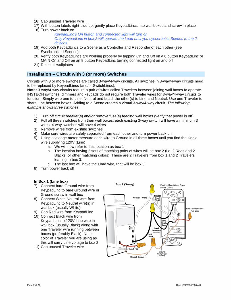
Installation – Circuit with 3 (or more) Switches Circuits with 3 or more switches are called 3-way/4-way circuits. All switches in 3-way/4-way circuits need to be replaced by KeypadLincs (and/or SwitchLincs). Note: 3-way/4-way circuits require a pair of wires called Travelers between joining wall boxes to operate. INSTEON switches, dimmers and keypads do not require both Traveler wires for 3-way/4-way circuits to function. Simply wire one to Line, Neutral and Load; the other(s) to Line and Neutral. Use one Traveler to share Line between boxes. Adding to a Scene creates a virtual 3-way/4-way circuit. The following example shows three switches.
1) Turn off circuit breaker(s) and/or remove fuse(s) feeding wall boxes (verify that power is off) 2) Pull all three switches from their wall boxes, each existing 3-way switch will have a minimum 3
wires; 4-way switches will have 4 wires 3) Remove wires from existing switches 4) Make sure wires are safely separated from each other and turn power back on 5) Using a voltage meter measure each wire to Ground in all three boxes until you find the single
wire supplying 120V (Line) a. We will now refer to that location as box 1 b. The location having 2 sets of matching pairs of wires will be box 2 (i.e. 2 Reds and 2
Blacks, or other matching colors). These are 2 Travelers from box 1 and 2 Travelers leading to box 3.
c. The last box will have the Load wire, that will be box 3 6) Turn power back off
In Box 1 (Line box) 7) Connect bare Ground wire from
KeypadLinc to bare Ground wire or Ground screw in wall box
8) Connect White Neutral wire from KeypadLinc to Neutral wire(s) in wall box (usually White)
9) Cap Red wire from KeypadLinc 10) Connect Black wire from
KeypadLinc to 120V Line wire in wall box (usually Black) along with one Traveler wire running between boxes (preferably Black). Note color of Traveler you are using as this will carry Line voltage to box 2
11) Cap unused Traveler wire
Page 8 of 24 Rev: 1/21/2014 7:36 AM
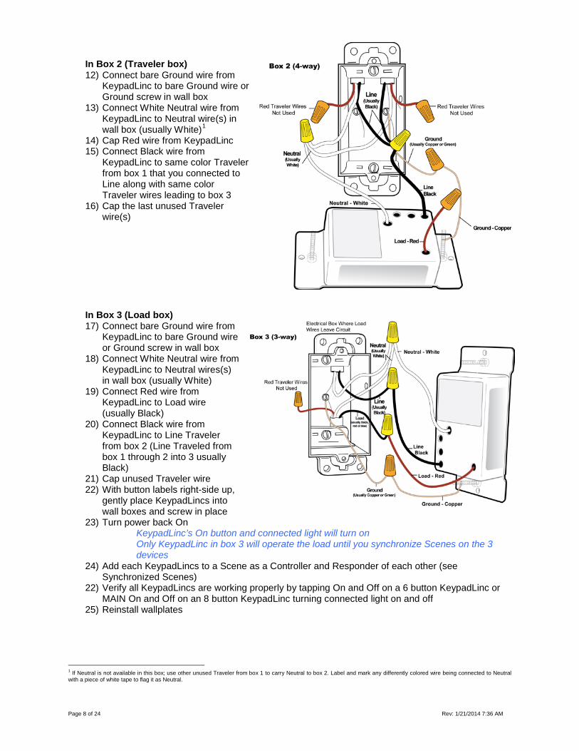
In Box 2 (Traveler box) 12) Connect bare Ground wire from
KeypadLinc to bare Ground wire or Ground screw in wall box
13) Connect White Neutral wire from KeypadLinc to Neutral wire(s) in wall box (usually White)1
14) Cap Red wire from KeypadLinc 15) Connect Black wire from
KeypadLinc to same color Traveler from box 1 that you connected to Line along with same color Traveler wires leading to box 3
16) Cap the last unused Traveler wire(s)
In Box 3 (Load box) 17) Connect bare Ground wire from
KeypadLinc to bare Ground wire or Ground screw in wall box
18) Connect White Neutral wire from KeypadLinc to Neutral wires(s) in wall box (usually White)
19) Connect Red wire from KeypadLinc to Load wire (usually Black)
20) Connect Black wire from KeypadLinc to Line Traveler from box 2 (Line Traveled from box 1 through 2 into 3 usually Black)
21) Cap unused Traveler wire 22) With button labels right-side up,
gently place KeypadLincs into wall boxes and screw in place
23) Turn power back On KeypadLinc’s On button and connected light will turn on Only KeypadLinc in box 3 will operate the load until you synchronize Scenes on the 3 devices
24) Add each KeypadLincs to a Scene as a Controller and Responder of each other (see Synchronized Scenes)
22) Verify all KeypadLincs are working properly by tapping On and Off on a 6 button KeypadLinc or MAIN On and Off on an 8 button KeypadLinc turning connected light on and off
25) Reinstall wallplates
1 If Neutral is not available in this box; use other unused Traveler from box 1 to carry Neutral to box 2. Label and mark any differently colored wire being connected to Neutral with a piece of white tape to flag it as Neutral.
Page 9 of 24 Rev: 1/21/2014 7:36 AM
Using KeypadLinc
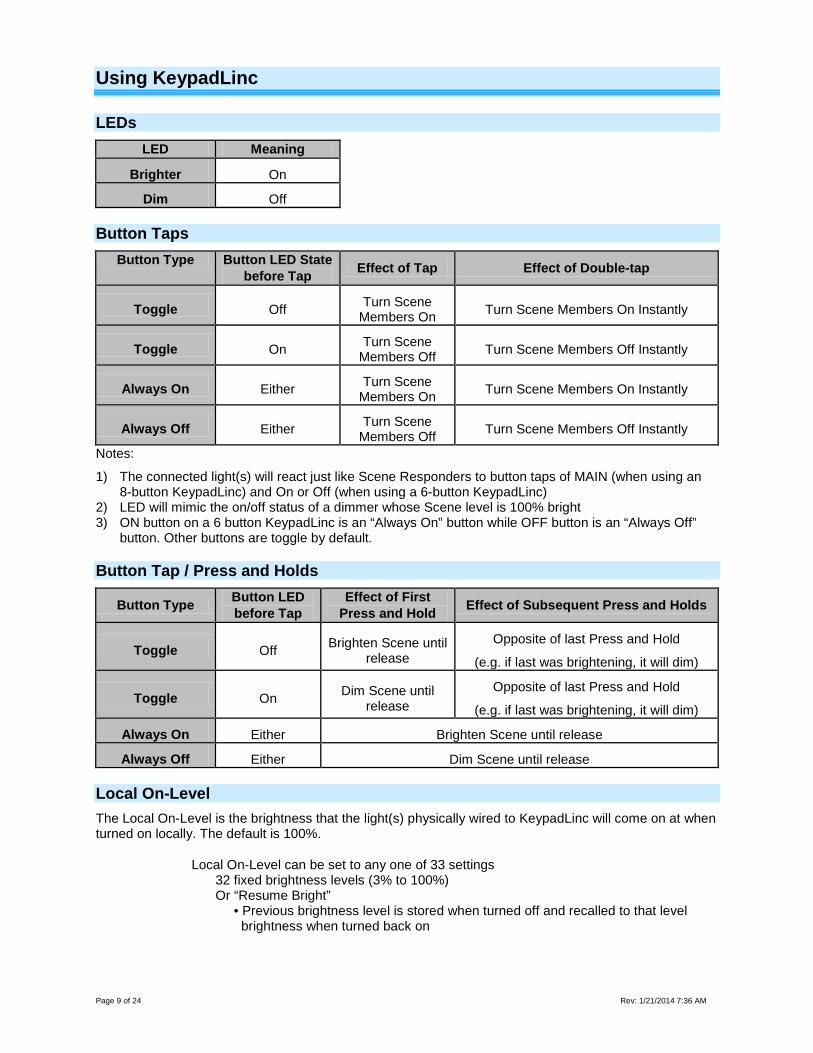
LEDs LED Meaning
Brighter On
Dim Off
Button Taps Button Type Button LED State
before Tap Effect of Tap Effect of Double-tap
Toggle Off Turn Scene Members On Turn Scene Members On Instantly
Toggle On Turn Scene Members Off Turn Scene Members Off Instantly
Always On Either Turn Scene Members On Turn Scene Members On Instantly
Always Off Either Turn Scene Members Off Turn Scene Members Off Instantly
Notes:
1) The connected light(s) will react just like Scene Responders to button taps of MAIN (when using an 8-button KeypadLinc) and On or Off (when using a 6-button KeypadLinc)
2) LED will mimic the on/off status of a dimmer whose Scene level is 100% bright 3) ON button on a 6 button KeypadLinc is an “Always On” button while OFF button is an “Always Off”
button. Other buttons are toggle by default.
Button Tap / Press and Holds
Button Type Button LED before Tap
Effect of First Press and Hold Effect of Subsequent Press and Holds
Toggle Off Brighten Scene until release
Opposite of last Press and Hold
(e.g. if last was brightening, it will dim)
Toggle On Dim Scene until release
Opposite of last Press and Hold
(e.g. if last was brightening, it will dim)
Always On Either Brighten Scene until release
Always Off Either Dim Scene until release
Local On-Level The Local On-Level is the brightness that the light(s) physically wired to KeypadLinc will come on at when turned on locally. The default is 100%.
Local On-Level can be set to any one of 33 settings 32 fixed brightness levels (3% to 100%) Or “Resume Bright” • Previous brightness level is stored when turned off and recalled to that level brightness when turned back on
Page 10 of 24 Rev: 1/21/2014 7:36 AM
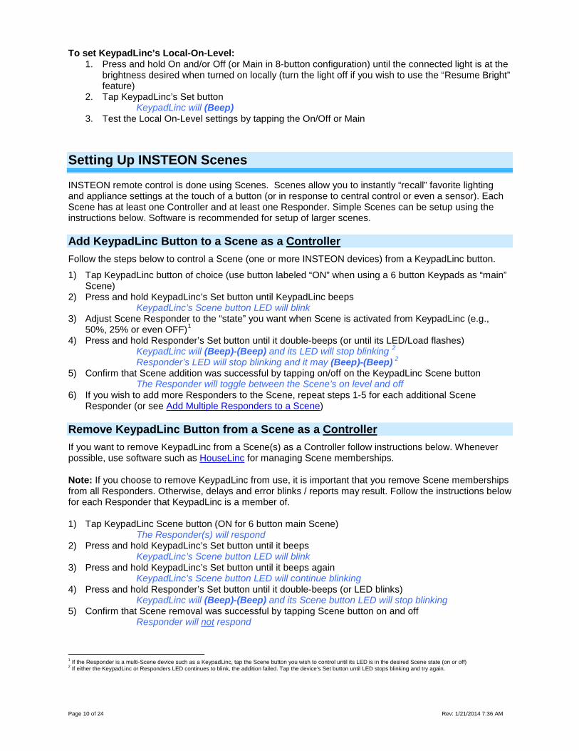
To set KeypadLinc’s Local-On-Level: 1. Press and hold On and/or Off (or Main in 8-button configuration) until the connected light is at the
brightness desired when turned on locally (turn the light off if you wish to use the “Resume Bright” feature)
2. Tap KeypadLinc’s Set button KeypadLinc will (Beep)
3. Test the Local On-Level settings by tapping the On/Off or Main
Setting Up INSTEON Scenes
INSTEON remote control is done using Scenes. Scenes allow you to instantly “recall” favorite lighting and appliance settings at the touch of a button (or in response to central control or even a sensor). Each Scene has at least one Controller and at least one Responder. Simple Scenes can be setup using the instructions below. Software is recommended for setup of larger scenes.
Add KeypadLinc Button to a Scene as a Controller Follow the steps below to control a Scene (one or more INSTEON devices) from a KeypadLinc button.
1) Tap KeypadLinc button of choice (use button labeled “ON” when using a 6 button Keypads as “main” Scene)
2) Press and hold KeypadLinc’s Set button until KeypadLinc beeps KeypadLinc’s Scene button LED will blink 3) Adjust Scene Responder to the “state” you want when Scene is activated from KeypadLinc (e.g.,
50%, 25% or even OFF)1 4) Press and hold Responder’s Set button until it double-beeps (or until its LED/Load flashes) KeypadLinc will (Beep)-(Beep) and its LED will stop blinking 2 Responder’s LED will stop blinking and it may (Beep)-(Beep) 2 5) Confirm that Scene addition was successful by tapping on/off on the KeypadLinc Scene button The Responder will toggle between the Scene’s on level and off 6) If you wish to add more Responders to the Scene, repeat steps 1-5 for each additional Scene
Responder (or see Add Multiple Responders to a Scene)
Remove KeypadLinc Button from a Scene as a Controller If you want to remove KeypadLinc from a Scene(s) as a Controller follow instructions below. Whenever possible, use software such as HouseLinc for managing Scene memberships.
Note: If you choose to remove KeypadLinc from use, it is important that you remove Scene memberships from all Responders. Otherwise, delays and error blinks / reports may result. Follow the instructions below for each Responder that KeypadLinc is a member of. 1) Tap KeypadLinc Scene button (ON for 6 button main Scene)
The Responder(s) will respond 2) Press and hold KeypadLinc’s Set button until it beeps KeypadLinc’s Scene button LED will blink 3) Press and hold KeypadLinc’s Set button until it beeps again KeypadLinc’s Scene button LED will continue blinking 4) Press and hold Responder’s Set button until it double-beeps (or LED blinks) KeypadLinc will (Beep)-(Beep) and its Scene button LED will stop blinking 5) Confirm that Scene removal was successful by tapping Scene button on and off Responder will not respond
1 If the Responder is a multi-Scene device such as a KeypadLinc, tap the Scene button you wish to control until its LED is in the desired Scene state (on or off) 2 If either the KeypadLinc or Responders LED continues to blink, the addition failed. Tap the device’s Set button until LED stops blinking and try again.
Page 11 of 24 Rev: 1/21/2014 7:36 AM
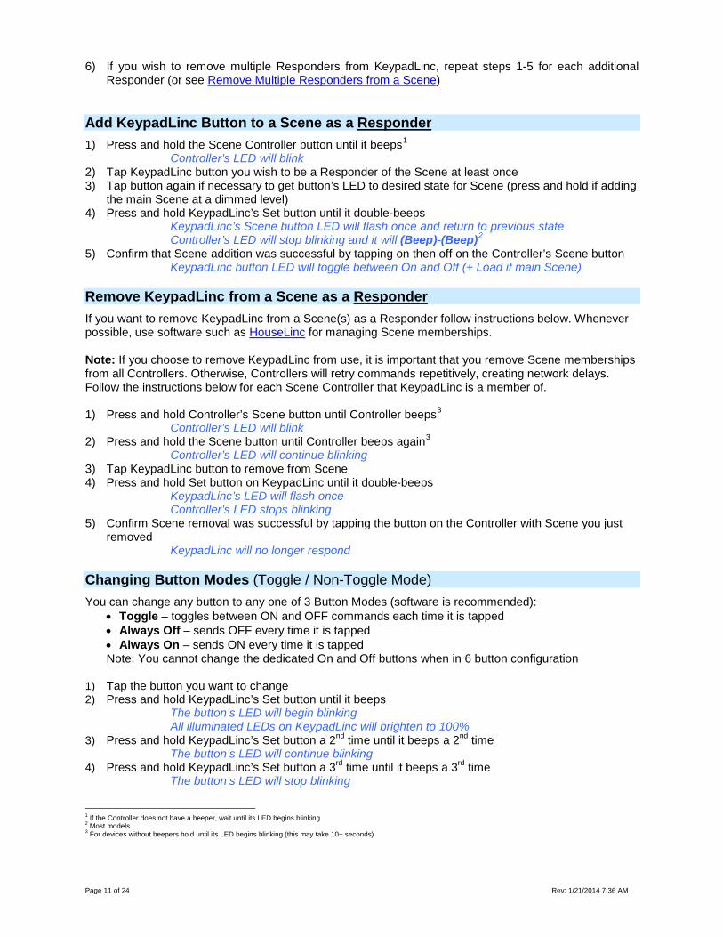
6) If you wish to remove multiple Responders from KeypadLinc, repeat steps 1-5 for each additional Responder (or see Remove Multiple Responders from a Scene)
Add KeypadLinc Button to a Scene as a Responder 1) Press and hold the Scene Controller button until it beeps1 Controller’s LED will blink 2) Tap KeypadLinc button you wish to be a Responder of the Scene at least once 3) Tap button again if necessary to get button’s LED to desired state for Scene (press and hold if adding
the main Scene at a dimmed level) 4) Press and hold KeypadLinc’s Set button until it double-beeps KeypadLinc’s Scene button LED will flash once and return to previous state Controller’s LED will stop blinking and it will (Beep)-(Beep)2 5) Confirm that Scene addition was successful by tapping on then off on the Controller’s Scene button KeypadLinc button LED will toggle between On and Off (+ Load if main Scene)
Remove KeypadLinc from a Scene as a Responder If you want to remove KeypadLinc from a Scene(s) as a Responder follow instructions below. Whenever possible, use software such as HouseLinc for managing Scene memberships.
Note: If you choose to remove KeypadLinc from use, it is important that you remove Scene memberships from all Controllers. Otherwise, Controllers will retry commands repetitively, creating network delays. Follow the instructions below for each Scene Controller that KeypadLinc is a member of. 1) Press and hold Controller’s Scene button until Controller beeps3
Controller’s LED will blink 2) Press and hold the Scene button until Controller beeps again3
Controller’s LED will continue blinking 3) Tap KeypadLinc button to remove from Scene 4) Press and hold Set button on KeypadLinc until it double-beeps
KeypadLinc’s LED will flash once Controller’s LED stops blinking
5) Confirm Scene removal was successful by tapping the button on the Controller with Scene you just removed
KeypadLinc will no longer respond
Changing Button Modes (Toggle / Non-Toggle Mode) You can change any button to any one of 3 Button Modes (software is recommended):
• Toggle – toggles between ON and OFF commands each time it is tapped • Always Off – sends OFF every time it is tapped • Always On – sends ON every time it is tapped Note: You cannot change the dedicated On and Off buttons when in 6 button configuration
1) Tap the button you want to change 2) Press and hold KeypadLinc’s Set button until it beeps
The button’s LED will begin blinking All illuminated LEDs on KeypadLinc will brighten to 100%
3) Press and hold KeypadLinc’s Set button a 2nd time until it beeps a 2nd time The button’s LED will continue blinking
4) Press and hold KeypadLinc’s Set button a 3rd time until it beeps a 3rd time The button’s LED will stop blinking
1 If the Controller does not have a beeper, wait until its LED begins blinking 2 Most models 3 For devices without beepers hold until its LED begins blinking (this may take 10+ seconds)
Page 12 of 24 Rev: 1/21/2014 7:36 AM
The button rotates to the next Button Mode in the cycle: Toggle → Always Off Always Off → Always On Always On → Toggle
5) Tap the button several times to confirm it is now in the desired state a. If you wish to rotate button mode again, return to step 2
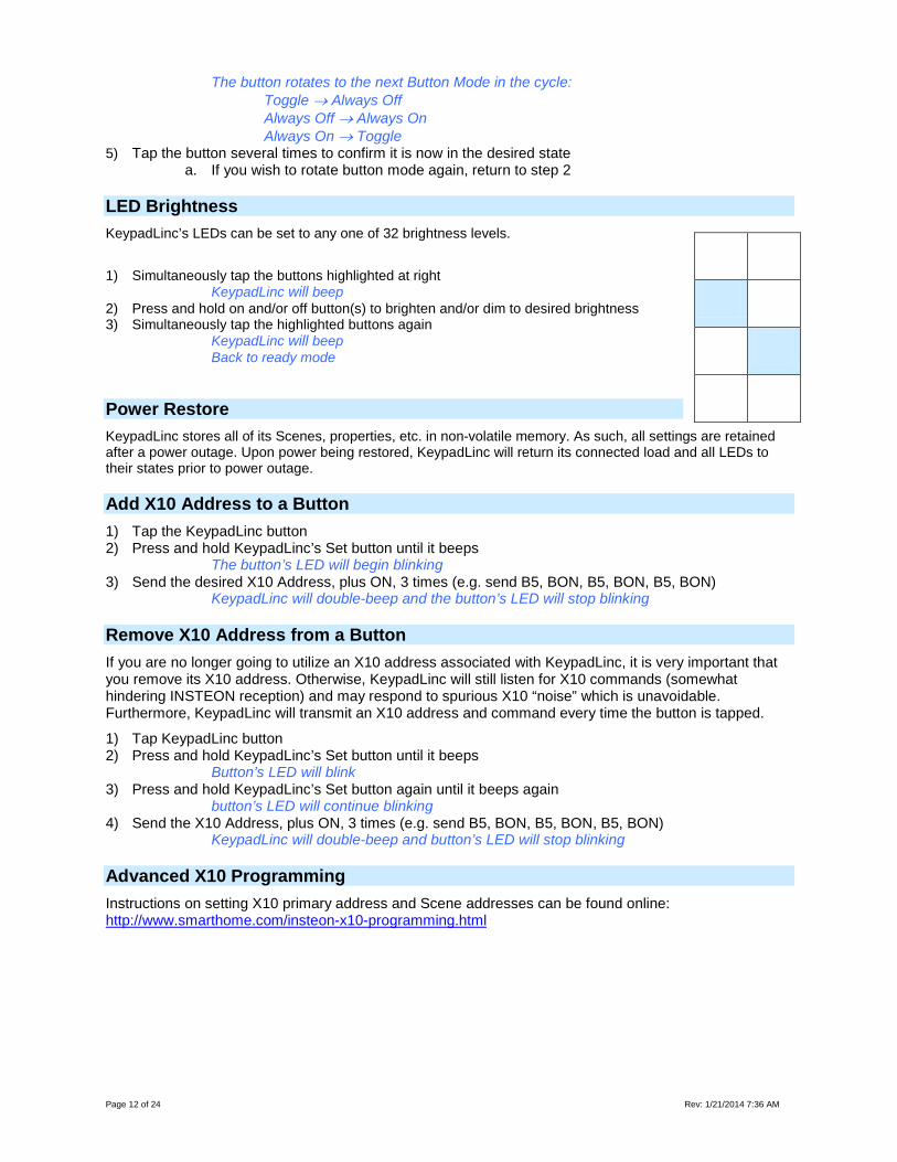
LED Brightness KeypadLinc’s LEDs can be set to any one of 32 brightness levels. 1) Simultaneously tap the buttons highlighted at right
KeypadLinc will beep 2) Press and hold on and/or off button(s) to brighten and/or dim to desired brightness 3) Simultaneously tap the highlighted buttons again
KeypadLinc will beep Back to ready mode
Power Restore
KeypadLinc stores all of its Scenes, properties, etc. in non-volatile memory. As such, all settings are retained after a power outage. Upon power being restored, KeypadLinc will return its connected load and all LEDs to their states prior to power outage.
Add X10 Address to a Button 1) Tap the KeypadLinc button 2) Press and hold KeypadLinc’s Set button until it beeps
The button’s LED will begin blinking 3) Send the desired X10 Address, plus ON, 3 times (e.g. send B5, BON, B5, BON, B5, BON)
KeypadLinc will double-beep and the button’s LED will stop blinking
Remove X10 Address from a Button If you are no longer going to utilize an X10 address associated with KeypadLinc, it is very important that you remove its X10 address. Otherwise, KeypadLinc will still listen for X10 commands (somewhat hindering INSTEON reception) and may respond to spurious X10 “noise” which is unavoidable. Furthermore, KeypadLinc will transmit an X10 address and command every time the button is tapped.
1) Tap KeypadLinc button 2) Press and hold KeypadLinc’s Set button until it beeps
Button’s LED will blink 3) Press and hold KeypadLinc’s Set button again until it beeps again
button’s LED will continue blinking 4) Send the X10 Address, plus ON, 3 times (e.g. send B5, BON, B5, BON, B5, BON)
KeypadLinc will double-beep and button’s LED will stop blinking
Advanced X10 Programming Instructions on setting X10 primary address and Scene addresses can be found online: http://www.smarthome.com/insteon-x10-programming.html
Page 13 of 24 Rev: 1/21/2014 7:36 AM
Advanced Features
Add Multiple Scene Responders (formerly “Multi-Linking Mode”)
1) Tap Scene Controller button on KeypadLinc 2) Press and hold KeypadLinc’s Set Button until it beeps
KeypadLinc’s Scene button LED will blink All illuminated LEDs on KeypadLinc will brighten to 100%
3) Tap KeypadLinc’s Set Button KeypadLinc’s Scene button LED will continue blinking
4) For each Responder you are adding a. Adjust Responder to desired Scene state (for KeypadLincs you must tap the button at
least once – until in desired state) b. Press and hold Responder’s Set button until it beeps (or LED flashes)
KeypadLinc will (Beep) 5) After all Responders have been added, tap KeypadLinc’s Set Button
KeypadLinc’s Scene button LED will stop blinking KeypadLinc’s LEDs will return to normal brightness 6) Test Scene by tapping Scene button a couple of times
All the Responders added above will respond
Remove Multiple Scene Responders (formerly “Multi-Unlinking Mode”)
1) Tap Scene Controller button on KeypadLinc 2) Press and hold KeypadLinc’s Set Button until it beeps
KeypadLinc’s Scene button LED will blink All illuminated LEDs on KeypadLinc will brighten to 100%
3) Press and hold KeypadLinc’s Set Button again until it beeps again KeypadLinc’s Scene button LED will continue blinking
4) Tap KeypadLinc’s Set Button KeypadLinc’s Scene button LED will continue blinking
5) For each Responder you are removing a. If a KeypadLinc button, tap button b. Press and hold Responder’s Set button until it beeps (or LED flashes)
6) After all Responders have been removed, Tap KeypadLinc’s Set Button KeypadLinc’s Scene button’s LED will stop blinking
KeypadLinc’s LEDs will return to normal brightness 7) Test Scene by tapping Scene button a couple of times
All the Responders removed will not respond
Synchronized Scenes (formerly “Cross-Linking”)
Synchronized Scenes are Scenes where all members stay synchronized. Common examples include 3-way lighting circuits and Scenes with a single Load bearing device. For our example we will Synchronize Scenes on 2 SwitchLincs and identify them as A and B. Example: 2 Switch Circuit 1) Turn both switches/dimmers on – to the desired (and same) Scene level 2) Press and hold Switch A’s Set button until it beeps (or LED blinks) Switch A’s LED will blink 3) Press and hold Switch B’s Set button until it double-beeps (or LED flashes) Switch B will (Beep)-(Beep) and its LED will flash once Switch A will (Beep)-(Beep) and its LED will stop blinking 4) Press and hold Switch B’s Set button until it beeps (or LED blinks) Switch B’s LED will blink 5) Press and hold Switch A’s Set button until it double-beeps (or LED flashes) Switch A will (Beep)-(Beep) and its LED will flash once
Page 14 of 24 Rev: 1/21/2014 7:36 AM
Switch B will (Beep)-(Beep) and its LED will stop blinking 6) Test the group by controlling the Load from Switch A and then Switch B The Load, Switch A’s status LED(s) and Switch B’s status LED(s) will all remain in synch Example: Synchronized Scene with numerous members Software is recommended, however, the following steps, when carefully followed, will also work. For our example we will Synchronize SwitchLincs 1 through “N” (where N = any number). 1) Turn all switches on – to the desired (and same) Scene level
a. Press and hold Switch 1’s Set button until it beeps (or LED blinks) Switch 1’s LED will blink
b. Tap Switch 1’s Set button Switch 1’s LED will continue blinking (it is now the Scene Controller)
c. For Switches 2 through N, press and hold the Set button on each, one at a time, until it double-beeps (or LED flashes)
Switch 2 through N will (Beep)-(Beep) and its LED will flash once d. Tap Switch 1’s Set button
Switches 2 through N are now Responders and Synchronized to Switch 1
2) Return to Step 1 above, systematically placing each of the remaining switches (2-N) into this step as the Scene Controller and all others as Responders of the Scene
All switches 1 – N are now synchronized as Scene Controllers and Scene Responders of all group members
Beep on Button Tap or Press Buttons can be set to Beep Mode so KeypadLinc will beep every time a button is used. (Default = Off) If KeypadLinc in 6-Button Configuration
Simultaneously tap the B and C buttons KeypadLinc will beep Keypad’s Beeper will toggle to on (if was off) or off (if it was on)
If KeypadLinc in 8-Button Configuration Simultaneously tap the D and E buttons
KeypadLinc will beep Keypad’s Beeper will toggle to on (if was off) or off (if it was on)
Page 15 of 24 Rev: 1/21/2014 7:36 AM
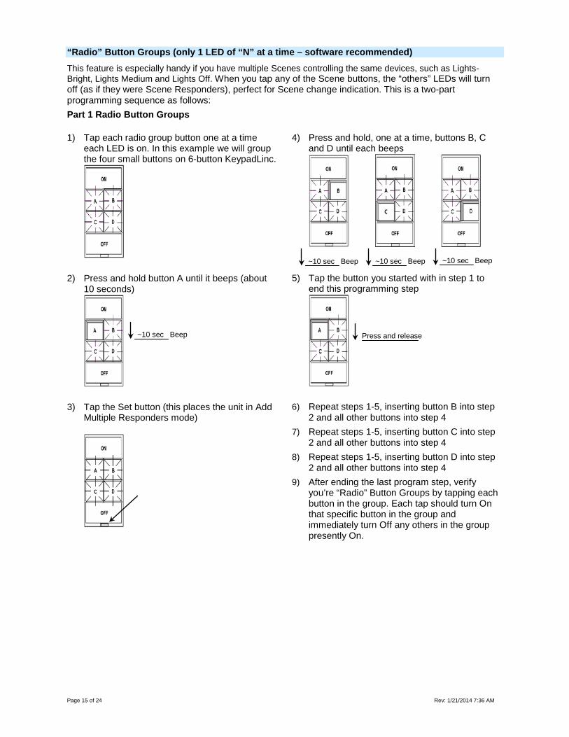
“Radio” Button Groups (only 1 LED of “N” at a time – software recommended) This feature is especially handy if you have multiple Scenes controlling the same devices, such as Lights-Bright, Lights Medium and Lights Off. When you tap any of the Scene buttons, the “others” LEDs will turn off (as if they were Scene Responders), perfect for Scene change indication. This is a two-part programming sequence as follows: Part 1 Radio Button Groups
1) Tap each radio group button one at a time each LED is on. In this example we will group the four small buttons on 6-button KeypadLinc.
2) Press and hold button A until it beeps (about 10 seconds)
3) Tap the Set button (this places the unit in Add Multiple Responders mode)
4) Press and hold, one at a time, buttons B, C and D until each beeps
5) Tap the button you started with in step 1 to end this programming step
6) Repeat steps 1-5, inserting button B into step 2 and all other buttons into step 4
7) Repeat steps 1-5, inserting button C into step 2 and all other buttons into step 4
8) Repeat steps 1-5, inserting button D into step 2 and all other buttons into step 4
9) After ending the last program step, verify you’re “Radio” Button Groups by tapping each button in the group. Each tap should turn On that specific button in the group and immediately turn Off any others in the group presently On.
~10 sec Beep ~10 sec Beep ~10 sec Beep
~10 sec Beep Press and release
Page 16 of 24 Rev: 1/21/2014 7:36 AM
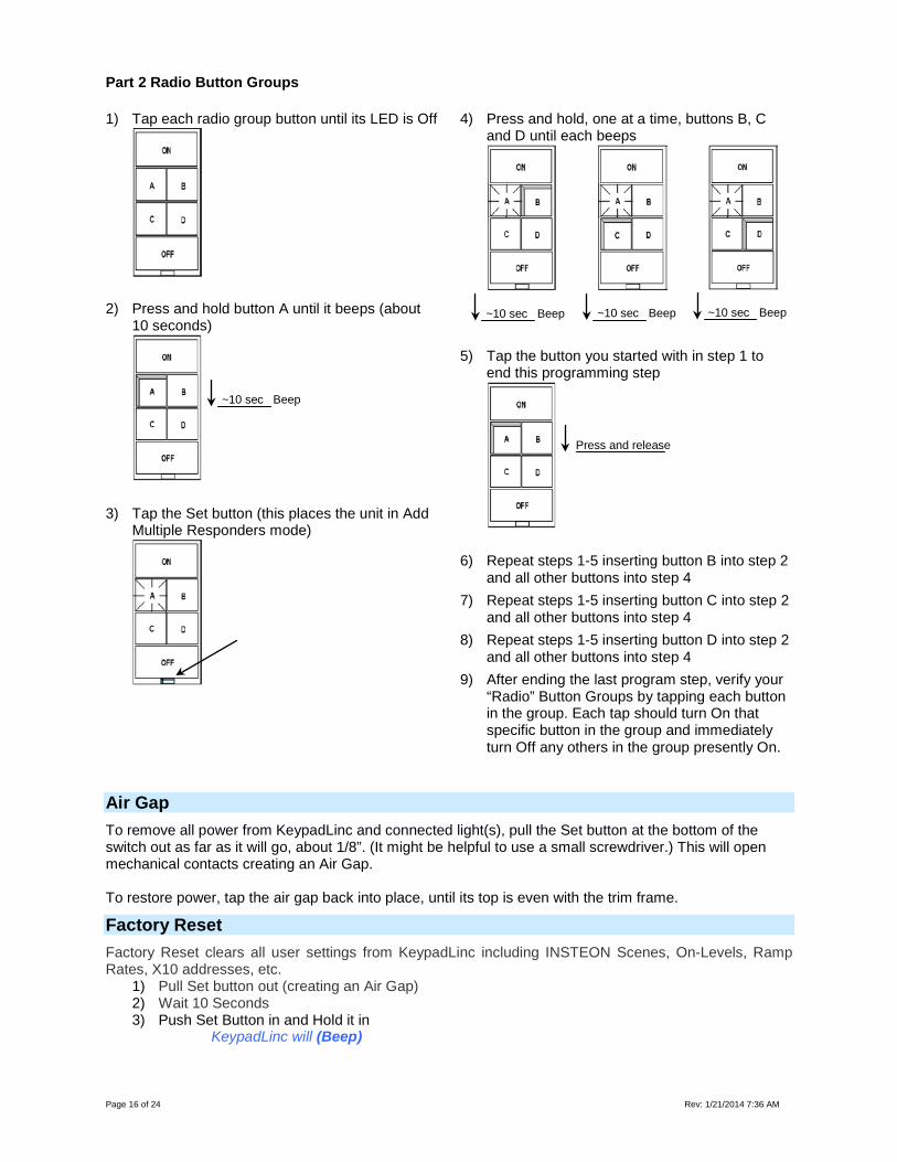
Part 2 Radio Button Groups
1) Tap each radio group button until its LED is Off
2) Press and hold button A until it beeps (about 10 seconds)
3) Tap the Set button (this places the unit in Add Multiple Responders mode)
4) Press and hold, one at a time, buttons B, C and D until each beeps
5) Tap the button you started with in step 1 to end this programming step
6) Repeat steps 1-5 inserting button B into step 2 and all other buttons into step 4
7) Repeat steps 1-5 inserting button C into step 2 and all other buttons into step 4
8) Repeat steps 1-5 inserting button D into step 2 and all other buttons into step 4
9) After ending the last program step, verify your “Radio” Button Groups by tapping each button in the group. Each tap should turn On that specific button in the group and immediately turn Off any others in the group presently On.
Air Gap To remove all power from KeypadLinc and connected light(s), pull the Set button at the bottom of the switch out as far as it will go, about 1/8”. (It might be helpful to use a small screwdriver.) This will open mechanical contacts creating an Air Gap. To restore power, tap the air gap back into place, until its top is even with the trim frame.
Factory Reset Factory Reset clears all user settings from KeypadLinc including INSTEON Scenes, On-Levels, Ramp Rates, X10 addresses, etc.
1) Pull Set button out (creating an Air Gap) 2) Wait 10 Seconds 3) Push Set Button in and Hold it in KeypadLinc will (Beep)
~10 sec Beep ~10 sec Beep ~10 sec Beep
Press and release
~10 sec Beep
Page 17 of 24 Rev: 1/21/2014 7:36 AM
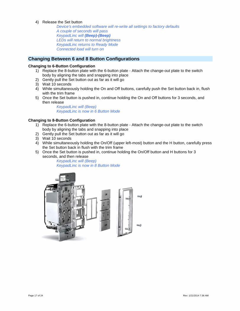
4) Release the Set button Device’s embedded software will re-write all settings to factory defaults A couple of seconds will pass KeypadLinc will (Beep)-(Beep) LEDs will return to normal brightness KeypadLinc returns to Ready Mode Connected load will turn on
Changing Between 6 and 8 Button Configurations Changing to 6-Button Configuration
1) Replace the 8-button plate with the 6-button plate - Attach the change-out plate to the switch body by aligning the tabs and snapping into place
2) Gently pull the Set button out as far as it will go 3) Wait 10 seconds 4) While simultaneously holding the On and Off buttons, carefully push the Set button back in, flush
with the trim frame 5) Once the Set button is pushed in, continue holding the On and Off buttons for 3 seconds, and
then release KeypadLinc will (Beep) KeypadLinc is now in 6 Button Mode
Changing to 8-Button Configuration
1) Replace the 6-button plate with the 8-button plate - Attach the change-out plate to the switch body by aligning the tabs and snapping into place
2) Gently pull the Set button out as far as it will go 3) Wait 10 seconds 4) While simultaneously holding the On/Off (upper left-most) button and the H button, carefully press
the Set button back in flush with the trim frame 5) Once the Set button is pushed in, continue holding the On/Off button and H buttons for 3
seconds, and then release KeypadLinc will (Beep) KeypadLinc is now in 8 Button Mode
Page 18 of 24 Rev: 1/21/2014 7:36 AM
Changing Buttons
KeypadLinc buttons can be changed to customize its appearance. Use care when removing the keycaps. Using a small, flat-edged screwdriver (ONLY) pry up on the sides of the keys from the middle of the keypad (when possible). Make sure you are centered on the key as to catch the small edge located there for this purpose. Also, please note that behind the buttons are clear plastic filler pieces which diffuse the LED’s light more elegantly. Use care to keep these filler pieces in the button frame as you re-assemble. Should any damage occur to KeypadLinc during customization, please contact 800-762-7845 and we will be happy to replace your frame.
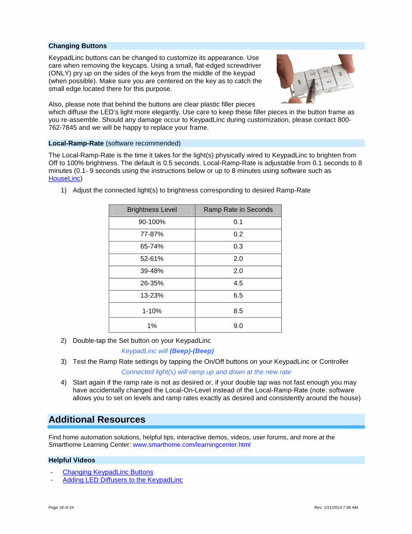
Local-Ramp-Rate (software recommended)
The Local-Ramp-Rate is the time it takes for the light(s) physically wired to KeypadLinc to brighten from Off to 100% brightness. The default is 0.5 seconds. Local-Ramp-Rate is adjustable from 0.1 seconds to 8 minutes (0.1- 9 seconds using the instructions below or up to 8 minutes using software such as HouseLinc)
1) Adjust the connected light(s) to brightness corresponding to desired Ramp-Rate
Brightness Level Ramp Rate in Seconds
90-100% 0.1
77-87% 0.2
65-74% 0.3
52-61% 2.0
39-48% 2.0
26-35% 4.5
13-23% 6.5
1-10% 8.5
1% 9.0
2) Double-tap the Set button on your KeypadLinc KeypadLinc will (Beep)-(Beep)
3) Test the Ramp Rate settings by tapping the On/Off buttons on your KeypadLinc or Controller Connected light(s) will ramp up and down at the new rate
4) Start again if the ramp rate is not as desired or, if your double tap was not fast enough you may have accidentally changed the Local-On-Level instead of the Local-Ramp-Rate (note: software allows you to set on levels and ramp rates exactly as desired and consistently around the house)
Additional Resources
Find home automation solutions, helpful tips, interactive demos, videos, user forums, and more at the Smarthome Learning Center: www.smarthome.com/learningcenter.html
Helpful Videos
- Changing KeypadLinc Buttons - Adding LED Diffusers to the KeypadLinc
Page 19 of 24 Rev: 1/21/2014 7:36 AM
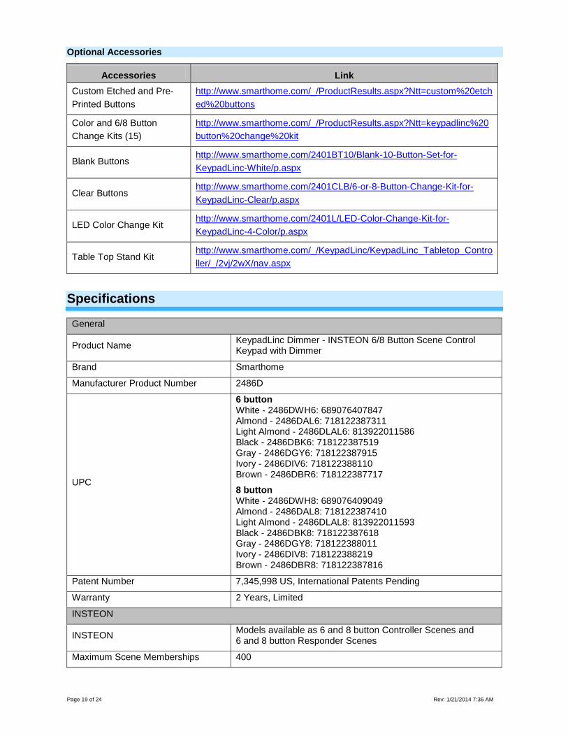
Optional Accessories
Accessories Link Custom Etched and Pre-Printed Buttons
http://www.smarthome.com/_/ProductResults.aspx?Ntt=custom%20etched%20buttons
Color and 6/8 Button Change Kits (15)
http://www.smarthome.com/_/ProductResults.aspx?Ntt=keypadlinc%20button%20change%20kit
Blank Buttons http://www.smarthome.com/2401BT10/Blank-10-Button-Set-for-KeypadLinc-White/p.aspx
Clear Buttons http://www.smarthome.com/2401CLB/6-or-8-Button-Change-Kit-for-KeypadLinc-Clear/p.aspx
LED Color Change Kit http://www.smarthome.com/2401L/LED-Color-Change-Kit-for-KeypadLinc-4-Color/p.aspx
Table Top Stand Kit http://www.smarthome.com/_/KeypadLinc/KeypadLinc_Tabletop_Controller/_/2vj/2wX/nav.aspx
Specifications
General
Product Name KeypadLinc Dimmer - INSTEON 6/8 Button Scene Control Keypad with Dimmer
Brand Smarthome
Manufacturer Product Number 2486D
UPC
6 button White - 2486DWH6: 689076407847 Almond - 2486DAL6: 718122387311 Light Almond - 2486DLAL6: 813922011586 Black - 2486DBK6: 718122387519 Gray - 2486DGY6: 718122387915 Ivory - 2486DIV6: 718122388110 Brown - 2486DBR6: 718122387717
8 button White - 2486DWH8: 689076409049 Almond - 2486DAL8: 718122387410 Light Almond - 2486DLAL8: 813922011593 Black - 2486DBK8: 718122387618 Gray - 2486DGY8: 718122388011 Ivory - 2486DIV8: 718122388219 Brown - 2486DBR8: 718122387816
Patent Number 7,345,998 US, International Patents Pending
Warranty 2 Years, Limited
INSTEON
INSTEON Models available as 6 and 8 button Controller Scenes and 6 and 8 button Responder Scenes
Maximum Scene Memberships 400

Page 20 of 24 Rev: 1/21/2014 7:36 AM
Brightness Levels 32 (256 with software)
Local On Level Adjustable, 32 levels plus Resume Dim
Local Ramp Rate Adjustable, 0.1 seconds to 8 seconds locally, 0.1 seconds to 9 minutes via software
Scene Commands Supported as Controller
On Off
Fast On Fast Off
Press and Hold Bright Press and Hold Dim
Scene Commands Supported as Responder
On Off
Fast On Fast Off
Incremental Bright Incremental Dim
Press and Hold Bright Press and Hold Dim
Software Configurable Yes, Always
RF Range 150’ Open air
X10 Support Yes
X10 Addresses 256 max, unassigned by default
INSTEON Device Category 0x01 Dimmable Lighting Control
INSTEON Device Subcategory 2486Dxx8 0x1C 2486Dxx6 0x1B
Mechanical
Mounting Standard, single gang wall box Wires 4, 16 gauge
Wires
Black - Line White - Neutral
Red - Load
Bare - Ground
Case Color Clear
Set Button 1
Plastic UV Stabilized Polycarbonate
Beeper Yes
LED 8, White
Dimensions 4.1" H x 1.8" W x 1.2" D
Weight 3.6 oz
Operating Environment Indoors
Operating Temperature Range 32-104 F
Operating Humidity Range 0-85% Relative Humidity
Electrical
Voltage 120VAC +/- 10%
Frequency 60Hz
Maximum Dimmer Load 600 Watts in a single gang box
Page 21 of 24 Rev: 1/21/2014 7:36 AM
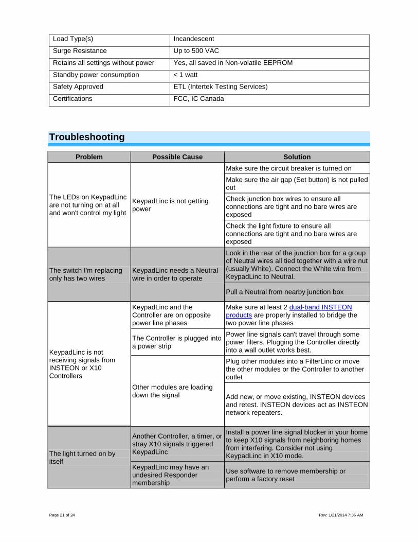
Load Type(s) Incandescent
Surge Resistance Up to 500 VAC
Retains all settings without power Yes, all saved in Non-volatile EEPROM
Standby power consumption < 1 watt
Safety Approved ETL (Intertek Testing Services)
Certifications FCC, IC Canada
Troubleshooting
Problem Possible Cause Solution
The LEDs on KeypadLinc are not turning on at all and won't control my light
KeypadLinc is not getting power
Make sure the circuit breaker is turned on Make sure the air gap (Set button) is not pulled out Check junction box wires to ensure all connections are tight and no bare wires are exposed Check the light fixture to ensure all connections are tight and no bare wires are exposed
The switch I'm replacing only has two wires
KeypadLinc needs a Neutral wire in order to operate
Look in the rear of the junction box for a group of Neutral wires all tied together with a wire nut (usually White). Connect the White wire from KeypadLinc to Neutral.
Pull a Neutral from nearby junction box
KeypadLinc is not receiving signals from INSTEON or X10 Controllers
KeypadLinc and the Controller are on opposite power line phases
Make sure at least 2 dual-band INSTEON products are properly installed to bridge the two power line phases
The Controller is plugged into a power strip
Power line signals can't travel through some power filters. Plugging the Controller directly into a wall outlet works best.
Other modules are loading down the signal
Plug other modules into a FilterLinc or move the other modules or the Controller to another outlet
Add new, or move existing, INSTEON devices and retest. INSTEON devices act as INSTEON network repeaters.
The light turned on by itself
Another Controller, a timer, or stray X10 signals triggered KeypadLinc
Install a power line signal blocker in your home to keep X10 signals from neighboring homes from interfering. Consider not using KeypadLinc in X10 mode.
KeypadLinc may have an undesired Responder membership
Use software to remove membership or perform a factory reset
Page 22 of 24 Rev: 1/21/2014 7:36 AM
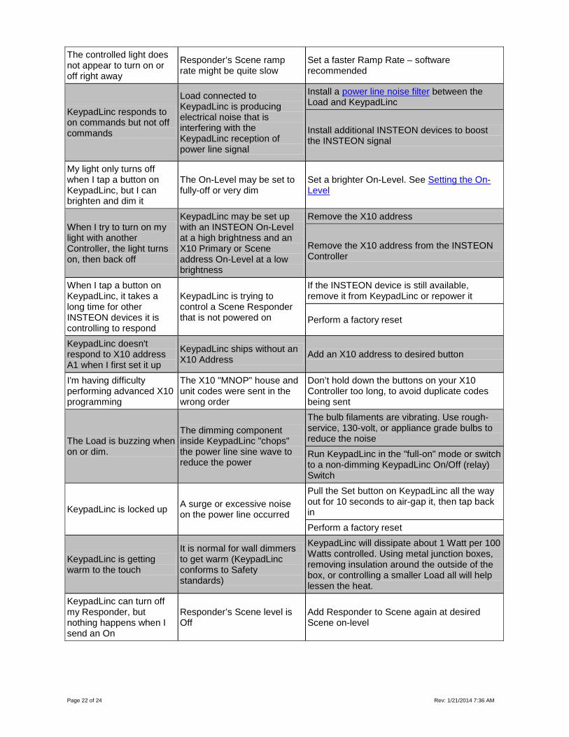
The controlled light does not appear to turn on or off right away
Responder’s Scene ramp rate might be quite slow
Set a faster Ramp Rate – software recommended
KeypadLinc responds to on commands but not off commands
Load connected to KeypadLinc is producing electrical noise that is interfering with the KeypadLinc reception of power line signal
Install a power line noise filter between the Load and KeypadLinc
Install additional INSTEON devices to boost the INSTEON signal
My light only turns off when I tap a button on KeypadLinc, but I can brighten and dim it
The On-Level may be set to fully-off or very dim
Set a brighter On-Level. See Setting the On-Level
When I try to turn on my light with another Controller, the light turns on, then back off
KeypadLinc may be set up with an INSTEON On-Level at a high brightness and an X10 Primary or Scene address On-Level at a low brightness
Remove the X10 address
Remove the X10 address from the INSTEON Controller
When I tap a button on KeypadLinc, it takes a long time for other INSTEON devices it is controlling to respond
KeypadLinc is trying to control a Scene Responder that is not powered on
If the INSTEON device is still available, remove it from KeypadLinc or repower it
Perform a factory reset
KeypadLinc doesn't respond to X10 address A1 when I first set it up
KeypadLinc ships without an X10 Address Add an X10 address to desired button
I'm having difficulty performing advanced X10 programming
The X10 "MNOP" house and unit codes were sent in the wrong order
Don’t hold down the buttons on your X10 Controller too long, to avoid duplicate codes being sent
The Load is buzzing when on or dim.
The dimming component inside KeypadLinc "chops" the power line sine wave to reduce the power
The bulb filaments are vibrating. Use rough-service, 130-volt, or appliance grade bulbs to reduce the noise Run KeypadLinc in the "full-on" mode or switch to a non-dimming KeypadLinc On/Off (relay) Switch
KeypadLinc is locked up A surge or excessive noise on the power line occurred
Pull the Set button on KeypadLinc all the way out for 10 seconds to air-gap it, then tap back in Perform a factory reset
KeypadLinc is getting warm to the touch
It is normal for wall dimmers to get warm (KeypadLinc conforms to Safety standards)
KeypadLinc will dissipate about 1 Watt per 100 Watts controlled. Using metal junction boxes, removing insulation around the outside of the box, or controlling a smaller Load all will help lessen the heat.
KeypadLinc can turn off my Responder, but nothing happens when I send an On
Responder’s Scene level is Off
Add Responder to Scene again at desired Scene on-level
Page 23 of 24 Rev: 1/21/2014 7:36 AM
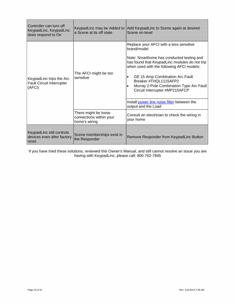
Controller can turn off KeypadLinc, KeypadLinc does respond to On
KeypadLinc may be Added to a Scene at its off state
Add KeypadLinc to Scene again at desired Scene on-level
KeypadLinc trips the Arc Fault Circuit Interrupter (AFCI)
The AFCI might be too sensitive
Replace your AFCI with a less sensitive brand/model Note: Smarthome has conducted testing and has found that KeypadLinc modules do not trip when used with the following AFCI models:
• GE 15 Amp Combination Arc Fault Breaker #THQL1115AFP2
• Murray 2-Pole Combination Type Arc Fault Circuit Interrupter #MP215AFCP
Install power line noise filter between the output and the Load
There might be loose connections within your home's wiring
Consult an electrician to check the wiring in your home
KeypadLinc still controls devices even after factory reset
Scene memberships exist in the Responder
Remove Responder from KeypadLinc Button
If you have tried these solutions, reviewed this Owner's Manual, and still cannot resolve an issue you are
having with KeypadLinc, please call: 800-762-7845
Page 24 of 24 Rev: 1/21/2014 7:36 AM
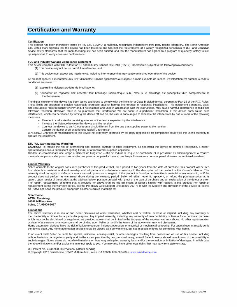
Certification and Warranty
Certification This product has been thoroughly tested by ITS ETL SEMKO, a nationally recognized independent third-party testing laboratory. The North American ETL Listed mark signifies that the device has been tested to and has met the requirements of a widely recognized consensus of U.S. and Canadian device safety standards, that the manufacturing site has been audited, and that the manufacturer has agreed to a program of quarterly factory follow-up inspections to verify continued conformance.
FCC and Industry Canada Compliance Statement This device complies with FCC Rules Part 15 and Industry Canada RSS-210 (Rev. 7). Operation is subject to the following two conditions:
(1) This device may not cause harmful interference, and
(2) This device must accept any interference, including interference that may cause undesired operation of the device.
Le present appareil est conforme aux CNR d'Industrie Canada applicables aux appareils radio exempts de licence. L'exploitation est autorise aux deux conditions suivantes:
(1) l'appareil ne doit pas produire de brouillage, et
(2) l'utilisateur de l'appareil doit accepter tout brouillage radiolectrique subi, mme si le brouillage est susceptible d'en compromettre le fonctionnement.
The digital circuitry of this device has been tested and found to comply with the limits for a Class B digital device, pursuant to Part 15 of the FCC Rules. These limits are designed to provide reasonable protection against harmful interference in residential installations. This equipment generates, uses, and can radiate radio frequency energy and, if not installed and used in accordance with the instructions, may cause harmful interference to radio and television reception. However, there is no guarantee that interference will not occur in a particular installation. If this device does cause such interference, which can be verified by turning the device off and on, the user is encouraged to eliminate the interference by one or more of the following measures:
- Re-orient or relocate the receiving antenna of the device experiencing the interference - Increase the distance between this device and the receiver - Connect the device to an AC outlet on a circuit different from the one that supplies power to the receiver - Consult the dealer or an experienced radio/TV technician
WARNING: Changes or modifications to this device not expressly approved by the party responsible for compliance could void the user’s authority to operate the equipment.
ETL / UL Warning (Safety Warning) CAUTION: To reduce the risk of overheating and possible damage to other equipment, do not install this device to control a receptacle, a motor-operated appliance, a fluorescent lighting fixture, or a transformer-supplied appliance. Gradateurs commandant une lampe a filament de tungstene – afin de reduire le risqué de surchauffe et la possibilite d’endommagement a d’autres materiels, ne pas installer pour commander une prise, un appareil a moteur, une lampe fluorescente ou un appareil alimente par un transformateur.
Limited Warranty Seller warrants to the original consumer purchaser of this product that, for a period of two years from the date of purchase, this product will be free from defects in material and workmanship and will perform in substantial conformity to the description of the product in this Owner’s Manual. This warranty shall not apply to defects or errors caused by misuse or neglect. If the product is found to be defective in material or workmanship, or if the product does not perform as warranted above during the warranty period, Seller will either repair it, replace it, or refund the purchase price, at its option, upon receipt of the product at the address below, postage prepaid, with proof of the date of purchase and an explanation of the defect or error. The repair, replacement, or refund that is provided for above shall be the full extent of Seller’s liability with respect to this product. For repair or replacement during the warranty period, call the INSTEON Gold Support Line at 800-762-7845 with the Model # and Revision # of the device to receive an RMA# and send the product, along with all other required materials to: Smarthome ATTN: Receiving 16542 Millikan Ave. Irvine, CA 92606-5027
Limitations The above warranty is in lieu of and Seller disclaims all other warranties, whether oral or written, express or implied, including any warranty or merchantability or fitness for a particular purpose. Any implied warranty, including any warranty of merchantability or fitness for a particular purpose, which may not be disclaimed or supplanted as provided above shall be limited to the two-year of the express warranty above. No other representation or claim of any nature by any person shall be binding upon Seller or modify the terms of the above warranty and disclaimer. Home automation devices have the risk of failure to operate, incorrect operation, or electrical or mechanical tampering. For optimal use, manually verify the device state. Any home automation device should be viewed as a convenience, but not as a sole method for controlling your home.
In no event shall Seller be liable for special, incidental, consequential, or other damages resulting from possession or use of this device, including without limitation damage to property and, to the extent permitted by law, personal injury, even if Seller knew or should have known of the possibility of such damages. Some states do not allow limitations on how long an implied warranty lasts and/or the exclusion or limitation of damages, in which case the above limitations and/or exclusions may not apply to you. You may also have other legal rights that may vary from state to state.
U.S Patent No. 7,345,998, International patents pending © Copyright 2012 Smarthome, 16542 Millikan Ave., Irvine, CA 92606, 800-762-7845, www.smarthome.com