Kesme kuvveti-Kayma gerilmesi-Kayma akımı-Kayma merkezi
63
Kesme kuvveti-Kayma gerilmesi-Kayma akımı- Kayma merkezi Shear Forces-Shear stress Shear flow-Shear center
description
Kesme kuvveti-Kayma gerilmesi-Kayma akımı-Kayma merkezi. Shear Forces-Shear stress Shear flow-Shear center. Introduction. Transverse loading applied to a beam results in normal and shearing stresses in transverse sections. Distribution of normal and shearing stresses satisfies. - PowerPoint PPT Presentation
Transcript of Kesme kuvveti-Kayma gerilmesi-Kayma akımı-Kayma merkezi

Kesme kuvveti-Kayma gerilmesi-Kayma akımı-Kayma merkezi
Shear Forces-Shear stressShear flow-Shear center

6 - 2
Introduction
dAyMdAF
dAzMVdAF
dAzyMdAF
xzxzz
xyxyy
xyxzxxx
0
0
00
• Distribution of normal and shearing stresses satisfies
• Transverse loading applied to a beam results in normal and shearing stresses in transverse sections.
• When shearing stresses are exerted on the vertical faces of an element, equal stresses must be exerted on the horizontal faces
• Longitudinal shearing stresses must exist in any member subjected to transverse loading.

6 - 3
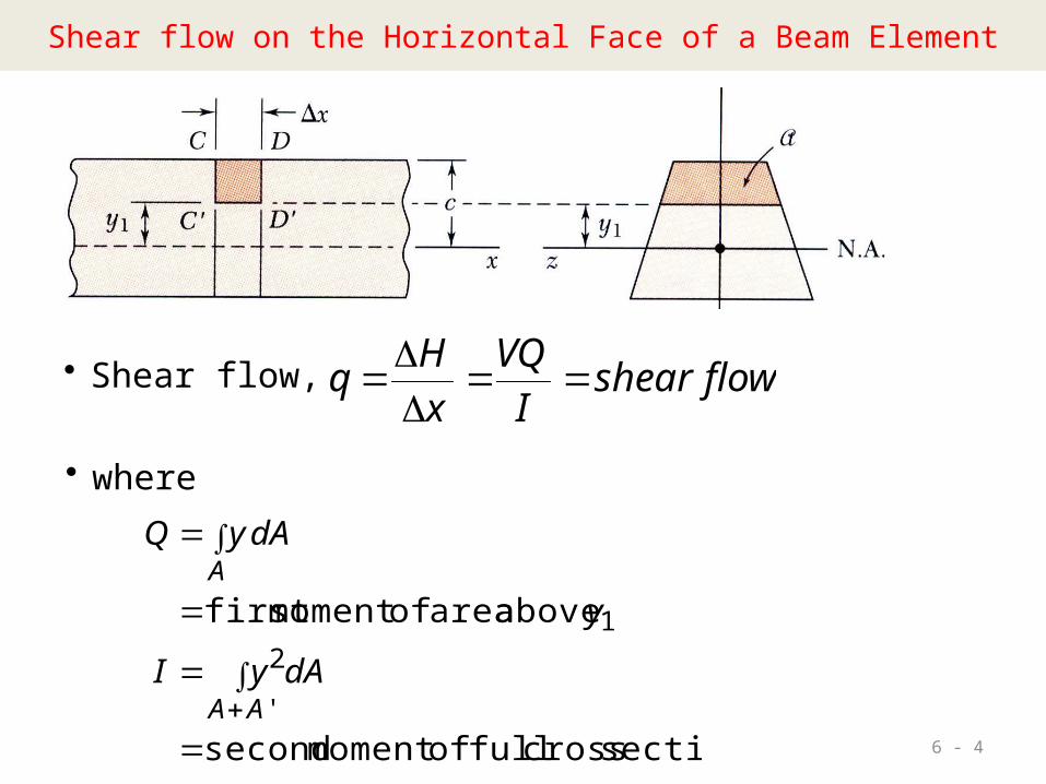
Shear flow on the Horizontal Face of a Beam Element
• Consider prismatic beam
• For equilibrium of beam element
A
CD
ADCx
dAyIMMH
dAHF 0
xVxdxdMMM
dAyQ
CD
A
• Note,
flowshearIVQ
xHq
xIVQH
• Substituting,
6 - 4
Shear flow on the Horizontal Face of a Beam Element
flowshearIVQ
xHq • Shear flow,
• where
section cross full ofmoment second
above area ofmoment first
'
21
AA
A
dAyI
y
dAyQ

6 - 5
Shear on the Horizontal Face of a Beam Element
• Same result is found for lower area
HH
qIQV
xHq
axis neutral torespect h moment witfirst
0

6 - 6
Shear Stress on the Horizontal Face of a Beam Element
IVQ
xHq
• Shear flow,
• Shear stress is found by dividing the shear flow q with bz.
zz IbVQ
bq
V
xy
zb
• Shear stress
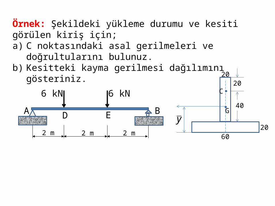
Örnek: Şekildeki yükleme durumu ve kesiti görülen kiriş için;a) C noktasındaki asal gerilmeleri ve doğrultularını bulunuz. b) Kesitteki kayma gerilmesi dağılımını gösteriniz.
2 m 2 m 2 m
6 kN 6 kN
A D E B
20
6020
20
40
y
C
G
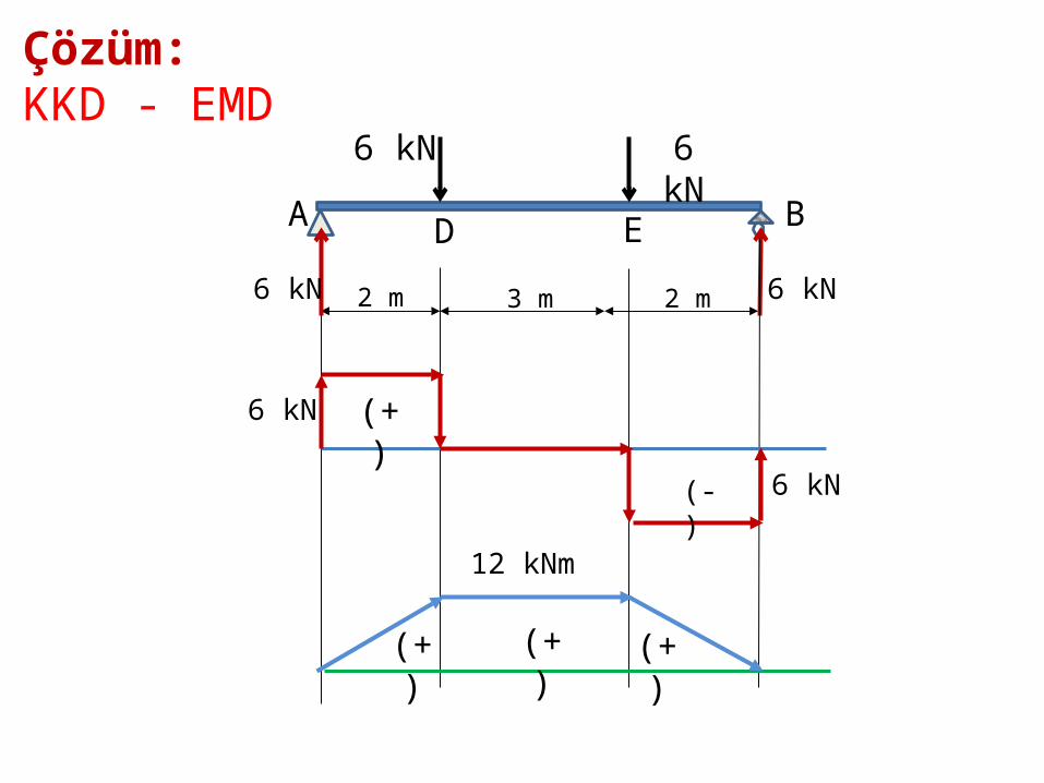
2 m 3 m 2 m
6 kN 6 kN
A D E B
Çözüm: KKD - EMD
6 kN 6 kN
6 kN
6 kN
(+)
(-)
(+) (+) (+)
12 kNm

20
6020
20
40
y
C
G
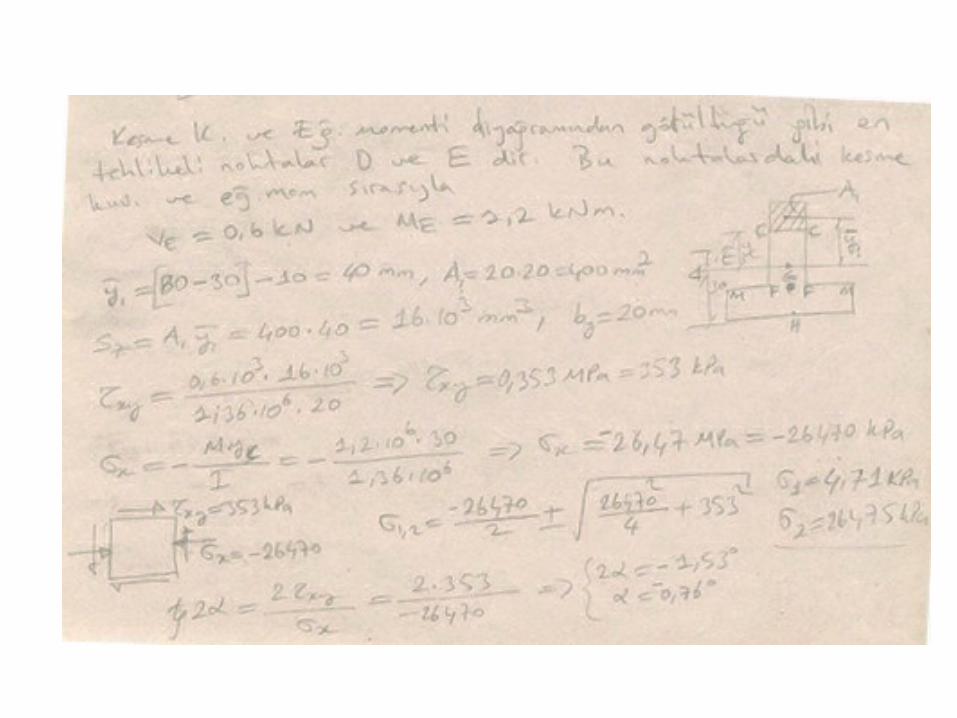
mmy 30
60206020106020506020
46
23
23
1036.1
3010602012
20603050602012
6020
mmI
I
z
z
Ağırlık merkezi ve Atalet momenti

Kesme Kuvveti-Kayma AkımıKayma Merkezi-Kayma Gerilmesi

Kesitteki iç kuvvetler:
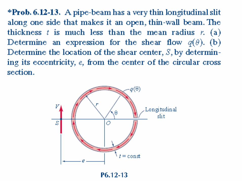
İNCE CİDARLI AÇIK KESİTLERDE KAYMA GERİLMELERİ VE KAYMA MERKEZİ
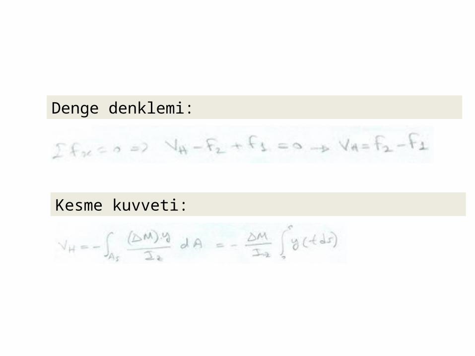
Denge denklemi:
Kesme kuvveti:
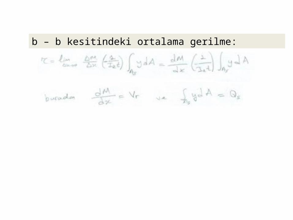
b – b kesitindeki ortalama gerilme:

Kayma Akımı:
Kayma Gerilmesi:
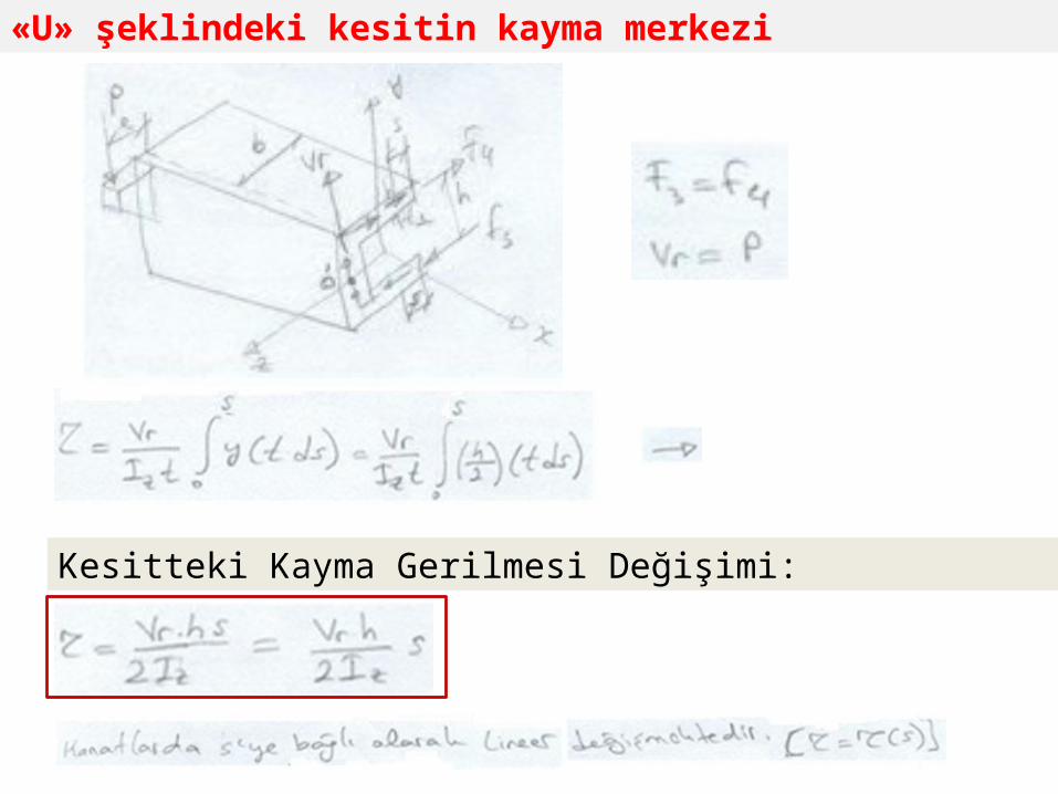
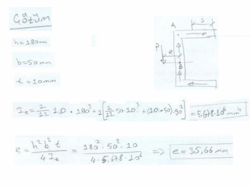
«U» şeklindeki kesitin kayma merkezi
Kesitteki Kayma Gerilmesi Değişimi:
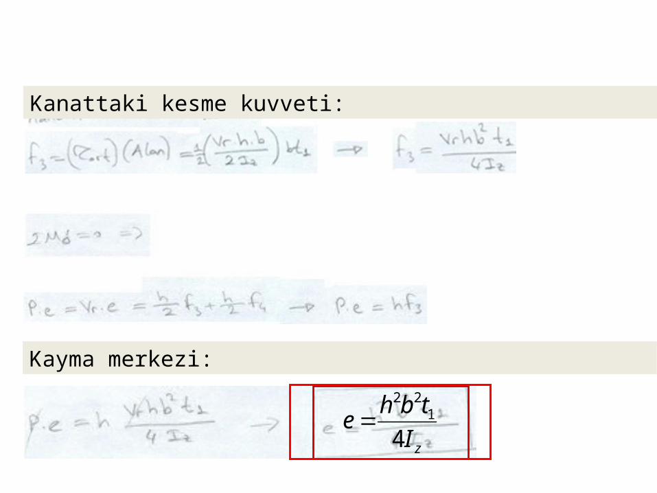
zItbhe
41
22
Kanattaki kesme kuvveti:
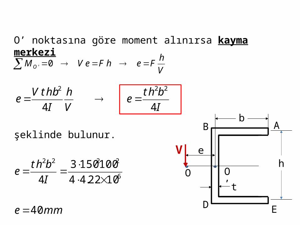
Kayma merkezi:
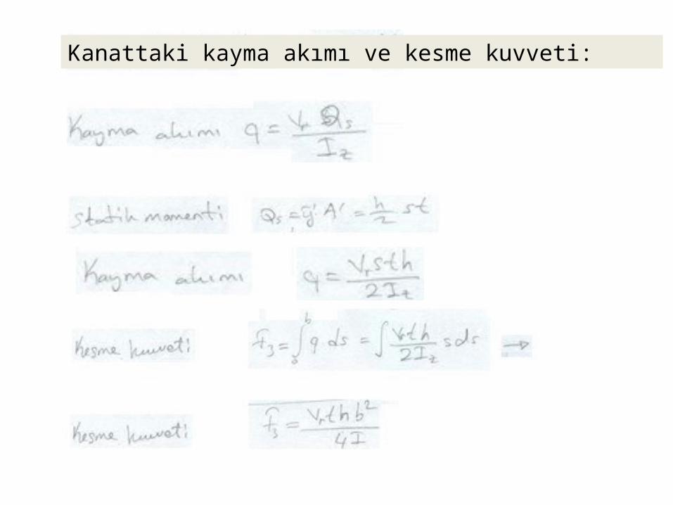
Kanattaki kayma akımı ve kesme kuvveti:

ÖRNEK: Şekilde görülen profil P=12 kN’luk bir kesme kuvvetine maruz kaldığına göre:a) Kayma merkezinin yerini bulunuz.b) Kesit çevresi boyunca kayma gerilmesi değişimini gösteriniz.

103105.85
18 MPa

ÖRNEK: Şekilde görülen profilin boyutları b=100 mm, h=150 mm ve t=3 mm olup profil P=800 N’luk bir kesme kuvvetine maruz bırakılmaktadır. Buna göre:a) Kayma merkezinin yerini bulunuz.b) Kesit çevresi boyunca kayma gerilmesi dağılımını gösteriniz.
e
b
h
tO O’
AB
D E

Çözüm:
e
b
h
tO O’
AB
D E
b=100 mmh=150 mmt=3 mm
462
4633
1022.41501006121503
veya
1022.41475.981535.101121
mmI
mmI
hbthI
hbtbtthI
III flangeweb
6121
21212
121
2
2
233

AB kolundaki kayma akımını bulmak için s uzunluğundaki bir eleman dikkate alınır.
sAB
D E
2hy
..ETA
2hy ve stA
sthsthAyQ22
sIhtVsht
IV
IQVq
22
Statik momenti:
Kayma akımı:
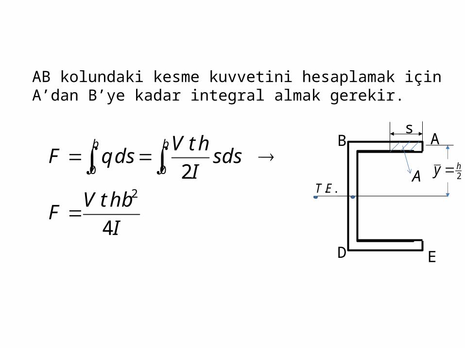
AB kolundaki kesme kuvvetini hesaplamak için A’dan B’ye kadar integral almak gerekir.
IhbtVF
sdsIhtVdsqF
bb
4
22
00
s
AB
D E
2hy
..ETA
mme
Ibhte
40
1022.441001503
4 6
2222
O’ noktasına göre moment alınırsa kayma merkezi
VhFehFeVMO 0'
Ibhte
Vh
IhbtVe
44
222
şeklinde bulunur.e
b
h
tO O’
AB
D E
V
s2hy
..ET
AB
D
max
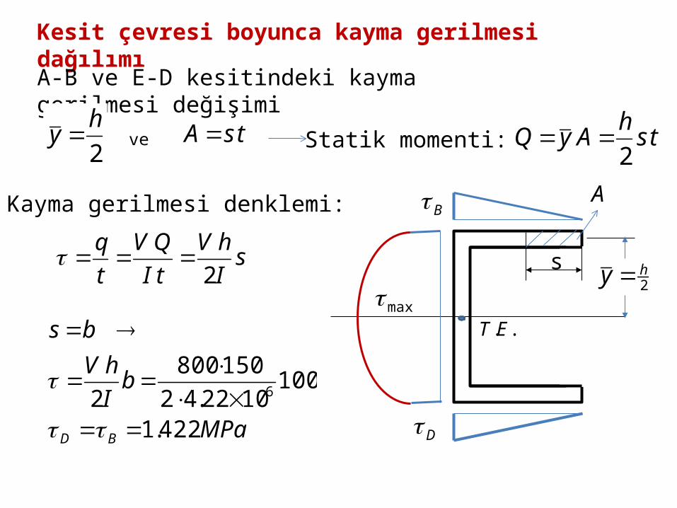
2hy ve tsA tshAyQ
2Statik momenti:
Kayma gerilmesi denklemi:
Kesit çevresi boyunca kayma gerilmesi dağılımı
sIhV
tIQV
tq
2
MPa
bIhV
bs
BD 422.1
1001022.42
1508002 6
A-B ve E-D kesitindeki kayma gerilmesi değişimi
33
4150
23150
42
4222211
1094.30100 mmbQ
ttbAyAyQhth
hhh
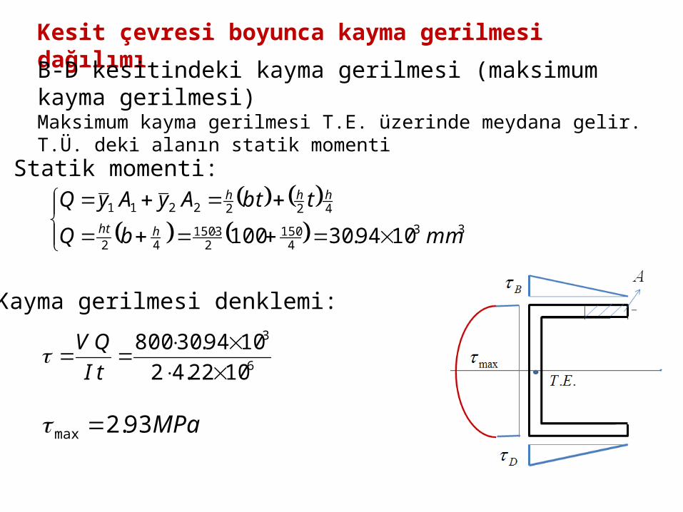
Statik momenti:
Kayma gerilmesi denklemi:
Kesit çevresi boyunca kayma gerilmesi dağılımı
6
3
1022.421094.30800
tIQV
MPa93.2max
B-D kesitindeki kayma gerilmesi (maksimum kayma gerilmesi)Maksimum kayma gerilmesi T.E. üzerinde meydana gelir. T.Ü. deki alanın statik momenti

6 - 29
Shearing Stresses in Thin-Walled Members• Consider a segment of a wide-flange
beam subjected to the vertical shear V.
• The longitudinal shear force on the element is
xIVQH
ItVQ
xtH
xzzx
• The corresponding shear stress is
• NOTE: 0xy0xz
in the flangesin the web
• Previously found a similar expression for the shearing stress in the web
ItVQ
xy

6 - 30
Shearing Stresses in Thin-Walled Members
• The variation of shear flow across the section depends only on the variation of the first moment.
IVQtq
• For a box beam, q grows smoothly from zero at A to a maximum at C and C’ and then decreases back to zero at E.
• The sense of q in the horizontal portions of the section may be deduced from the sense in the vertical portions or the sense of the shear V.

6 - 31
Sample Problem 6.3
Knowing that the vertical shear is 50 kips in a W10x68 rolled-steel beam, determine the horizontal shearing stresses in the top flange at the points a and C.

SOLUTION:• First moment for the shaded area,
3in98.15
in815.4in770.0in31.4
Q
Q
• The shear stress at a,
in770.0in394
in98.15kips504
3
ItVQ
ksi63.2

• First moment for the area over point C,
3in4.42
in215.2in770.0in43.4in815.4in770.0in40.9
Q
Q
• The shear stress at C,
in770.0in394
in4.42kips504
3
ItVQ
ksi989.6

- Craig


6 - 40
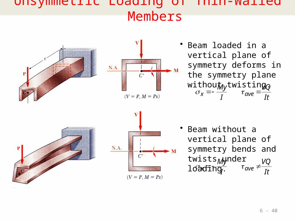
Unsymmetric Loading of Thin-Walled Members
• Beam loaded in a vertical plane of symmetry deforms in the symmetry plane without twisting.
ItVQ
IMy
avex
• Beam without a vertical plane of symmetry bends and twists under loading.
ItVQ
IMy
avex
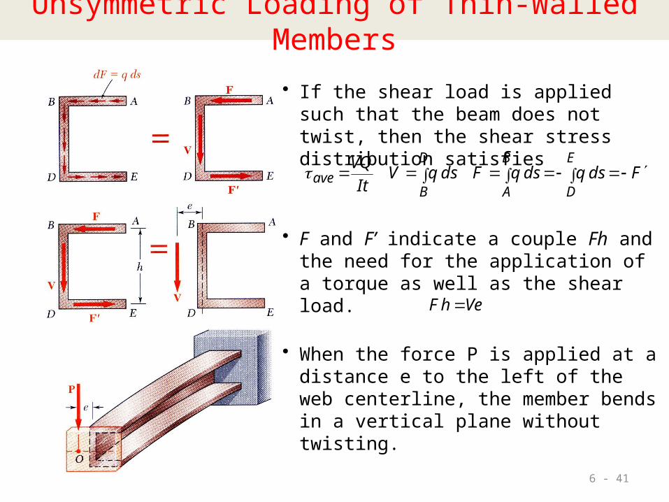
6 - 41
• When the force P is applied at a distance e to the left of the web centerline, the member bends in a vertical plane without twisting.
Unsymmetric Loading of Thin-Walled Members
• If the shear load is applied such that the beam does not twist, then the shear stress distribution satisfies
FdsqdsqFdsqVItVQ E
D
B
A
D
Bave
• F and F’ indicate a couple Fh and the need for the application of a torque as well as the shear load.
VehF

6 - 42
Example 6.05Determine the location for the shear center of the channel section with b = 4 in., h = 6 in., and t = 0.15 in.

6 - 43
Example 6.05• Inertia moment: • b = 4 in., h = 6 in., and t = 0.15 in.
hbthI
hbtbtthI
III flangeweb
6121
21212
121
2
2
233

6 - 44
Solution
IhFe
• where
IVthbF
dshstIVds
IVQdsqF
b bb
4
22
0 00
• Combining,
.in43.in62
in.4
32
bh
be .in6.1e

Shear stress in flanges• Determine the shear stress distribution for V = 2.5 kips.
ItVQ
tq
• Shearing stresses in the flanges,
ksi22.2
in6in46in6in15.0in4kips5.26
66
62
22
2121
B
B
B hbthVb
hbthVhb
sI
VhhstItV
ItVQ
6 - 46
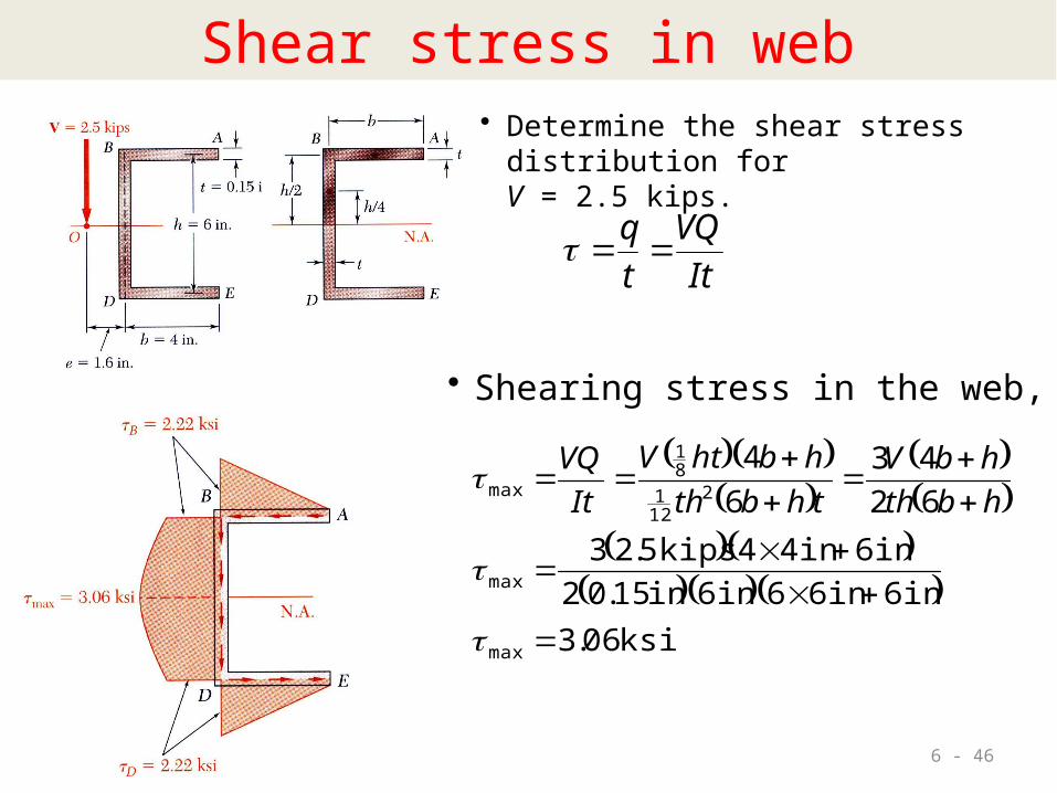
Shear stress in web• Determine the shear stress distribution for V = 2.5 kips.
ItVQ
tq
• Shearing stress in the web,
ksi06.3in6in66in6in15.02
in6in44kips5.236243
64
max
max
2121
81
max
hbthhbV
thbthhbhtV
ItVQ


t1 t2
b
Ph1 h2
Örnek: Şekilde kesiti görülen kirişina) Kayma merkezinin yerini bulunuz.b) Kanatlarda oluşan iç kuvvetleri hesaplayınız.
t =6 mm t1 =4 mm t2 =5 mm h1 =60 mm h2 =40 mm b=50 mm P=800 N
t
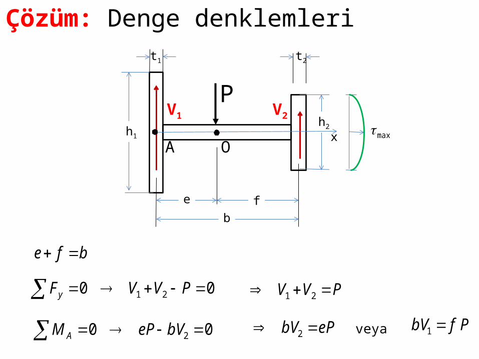
Çözüm: Denge denklemleri
00 21 PVVFy PVV 21
00 2 bVePM AePbV 2
PfbV 1veya
t1 t2
e fb
Ph1
h2
V1 V2
A Omaxx
bfe

43333 10567.99405650604121 mmI x
4332 10667.26405
121 mmI
4331 1072604
121 mmI
Atalet momentleri
Tüm kesitin Atalet momenti
Başlıkların atalet momentleri t1 t2
e fb
Ph1
h2
V1 V2
A Omax
x

xxx IhPhth
tIP
tIQV
842
222
22
22
2max
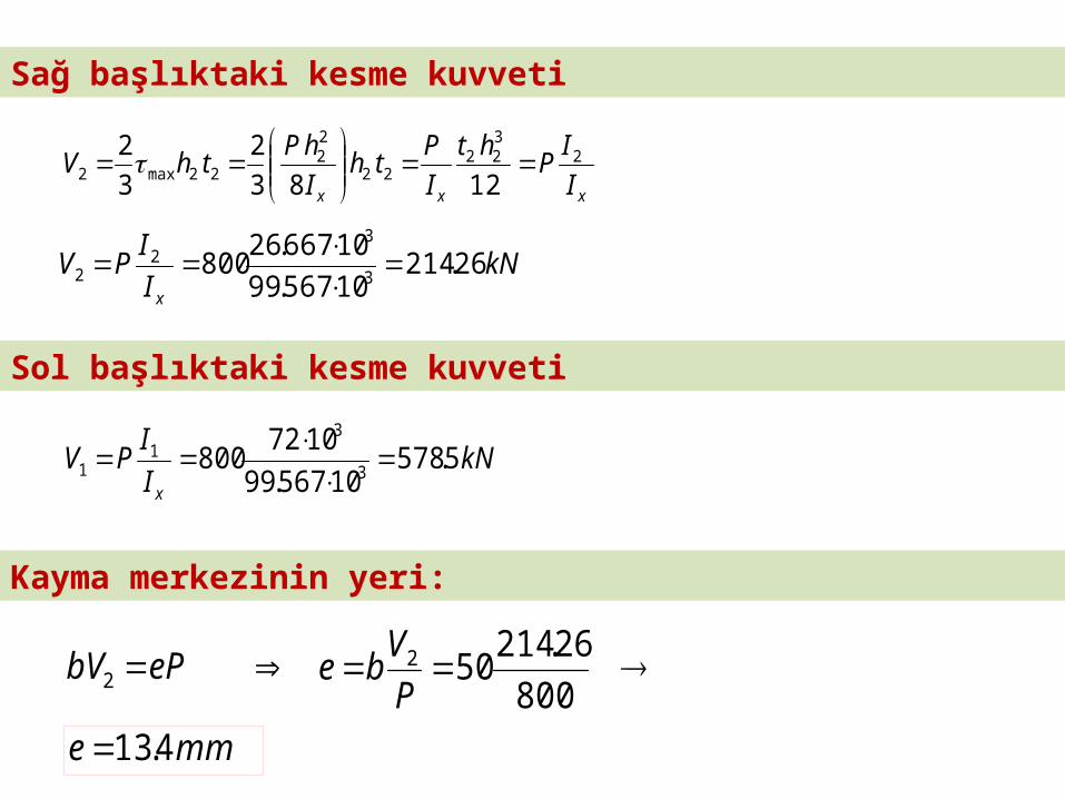
Sağ başlıktaki maksimum kayma gerilmesi
MPaIhP
x
61.110567.998
408008 3
222
max
xxx IIPht
IPth
IhPthV 2
322
22
22
22max2 12832
32
kNIIPVx
26.21410567.9910667.26800 3
32
2
kNIIPVx
5.57810567.99
1072800 3
31
1
ePbV 2 800
26.214502
PVbe
mme 4.13
Sağ başlıktaki kesme kuvveti
Sol başlıktaki kesme kuvveti
Kayma merkezinin yeri:

t
V
h
b
x
A
C
B
ED
b=100 mm
h=150 mm
t=3 mm
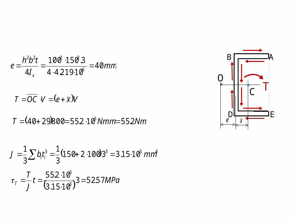
Example: For the channel section, and neglecting stress concentrations, determine the maximum shearing stress caused by a V=800-N vertical shear applied at centroid C of the section, which is located to the right of the center line of the web BD.x
x

Solution:
V
x
A
C
B
ED
=
e
V
x
A
C
B
ED
=
e
TV
x
A
C
B
EDe x
A
C
B
EDe
+ T

mmx 29
105030000
1503310025031002
46233 10219.4753100310012121503
121 mmI x
331094.302
75375753100 mmQ
MPatIQV
xV 956.1
310219.41094.30800
6
3
V
x
A
C
B
EDe
V
BB
D
D
x
A
C
B
EDe
T
mmItbhe
x
4010219.44
3.1501004 6
2222
O
VxeVOCT
4333 1015.33100215031
31 mmtbJ ii
MPatJT
T 57.5231015.3102.55
3
3
NmNmmT 2.55102.558002940 3

MPaTV 526.5457.52956.1max
The maximum shearing stress