Ultimate Guide to the Kerbal Space Program w Plane Instructions and Biomes
Upload
tomas-leon-juliaCategory
view
817download
93
1
Kerbal Space ProgramThe Missing Manual
(updated for version 0.24.2)Volume I
Author: Anthony de Araujo

2

Disclaimer
The information in this book is for informational purposes only.
Kerbal Space Program is a product developed by Squad. It is currently inthe alpha stage, but has been available for early access purchase for around2 years.
I am not a lawyer or a rocket scientist, nor am I affiliated with the pro-ducers of the Kerbal Space Program game.
Any advice that I give in this publication is my opinion based on my ownexperience with the game and research I have done about the subject.
The material in this book may include information, products or servicesby third parties. Third Party Materials are comprised of the products andopinions expressed by their owners.
As such, I do not assume responsibility or liability for any Third PartyMaterial or opinions.
The publication of such Third Party Materials does not constitute myguarantee of any information, instruction, opinion, products or services con-tained within the Third Party Material.
Publication of such Third Party Material is simply a recommendationand an expression of my own opinion of that material.
3
4
No part of this publication shall be reproduced or transmitted, in wholeor in part in any form, without the prior written consent of the author. Alltrademarks and registered trademarks appearing in this publication are theproperty of their respective owners.
Readers of this book are advised to do their own due diligence whenutilizing the information contained herein.
By reading the information contained in this publication, you agree thatthe author is not responsible for the success or failure when utilizing anyinformation presented.
Contents
1 About the Author 9
2 Introduction 11
2.1 What is Kerbal Space Program? . . . . . . . . . . . . . . . . . 11
2.2 About this book . . . . . . . . . . . . . . . . . . . . . . . . . . 12
2.3 Concepts . . . . . . . . . . . . . . . . . . . . . . . . . . . . . . 13
2.3.1 ∆v (Delta-v) . . . . . . . . . . . . . . . . . . . . . . . 13
2.3.2 Isp - Specific Impulse . . . . . . . . . . . . . . . . . . . 18
2.3.3 TWR - Thrust to Weight Ratio . . . . . . . . . . . . . 20
2.3.4 Staging . . . . . . . . . . . . . . . . . . . . . . . . . . 26
2.3.5 Attitude . . . . . . . . . . . . . . . . . . . . . . . . . . 29
2.3.6 Prograde/Retrograde . . . . . . . . . . . . . . . . . . . 31
2.3.7 RCS - Reaction Control System . . . . . . . . . . . . . 33
2.3.8 SAS - Stability Augmentation System . . . . . . . . . . 34
5
6 CONTENTS
2.4 Orbital Mechanics - The ”Mathy” part . . . . . . . . . . . . . 35
2.4.1 What is an Orbit? . . . . . . . . . . . . . . . . . . . . 35
2.4.2 Periapsis . . . . . . . . . . . . . . . . . . . . . . . . . . 36
2.4.3 Apoapsis . . . . . . . . . . . . . . . . . . . . . . . . . . 39
2.4.4 Semimajor Axis . . . . . . . . . . . . . . . . . . . . . . 40
2.4.5 Eccentricity . . . . . . . . . . . . . . . . . . . . . . . . 43
2.4.6 Inclination . . . . . . . . . . . . . . . . . . . . . . . . . 44
2.4.7 LAN - Longitude of Ascending Node . . . . . . . . . . 47
2.4.8 Argument of Periapsis (ω) . . . . . . . . . . . . . . . . 50
2.4.9 Mean Anomaly . . . . . . . . . . . . . . . . . . . . . . 50
2.4.10 Orbital Stability . . . . . . . . . . . . . . . . . . . . . 51
2.4.11 Lagrange Points . . . . . . . . . . . . . . . . . . . . . . 54
2.4.12 Altitude vs. Velocity . . . . . . . . . . . . . . . . . . . 56
2.4.13 Oberth Effect . . . . . . . . . . . . . . . . . . . . . . . 57
3 The Navball 63
3.1 Navball Indicators . . . . . . . . . . . . . . . . . . . . . . . . 65
3.1.1 Prograde . . . . . . . . . . . . . . . . . . . . . . . . . . 65
3.1.2 Retrograde . . . . . . . . . . . . . . . . . . . . . . . . 65
3.1.3 Target Prograde . . . . . . . . . . . . . . . . . . . . . . 66
3.1.4 Target Retrograde . . . . . . . . . . . . . . . . . . . . 67
3.1.5 Maneuver Node . . . . . . . . . . . . . . . . . . . . . . 67
3.1.6 Level Indicator . . . . . . . . . . . . . . . . . . . . . . 67
3.1.7 Other Navball Indicators . . . . . . . . . . . . . . . . . 68
3.1.8 Using the Navball To Change Your Attitude . . . . . . 69
3.1.9 Maneuver Nodes . . . . . . . . . . . . . . . . . . . . . 73
3.1.10 Executing Maneuvers . . . . . . . . . . . . . . . . . . . 81
CONTENTS 7
4 Orbital Maneuvers 85
4.1 Gravity Turn . . . . . . . . . . . . . . . . . . . . . . . . . . . 85
4.2 Circularizing your Orbit . . . . . . . . . . . . . . . . . . . . . 87
4.2.1 Achieving Orbit . . . . . . . . . . . . . . . . . . . . . . 87
4.2.2 Circularization . . . . . . . . . . . . . . . . . . . . . . 88
4.3 Changing your Orbital Inclination . . . . . . . . . . . . . . . . 96
4.4 Aerobraking . . . . . . . . . . . . . . . . . . . . . . . . . . . . 109
4.5 Rendezvous . . . . . . . . . . . . . . . . . . . . . . . . . . . . 122
4.6 Docking . . . . . . . . . . . . . . . . . . . . . . . . . . . . . . 155
4.7 Gravity Assist . . . . . . . . . . . . . . . . . . . . . . . . . . . 174
4.8 Landing . . . . . . . . . . . . . . . . . . . . . . . . . . . . . . 178

8 CONTENTS

Chapter 1
About the Author
I am a software developer with 30+ years of experience. Over the course ofmy professional career, I have also been a big game enthusiast during my freetime.
I’ve played everything from Tetris, Breakout, Duke Nukem and Doom toLeft 4 Dead, Portal, Space Engineers and, of course, Kerbal Space Program.
I am not a rocket scientist. I am simply an enthusiast of the game witha knack for research. All the concepts and descriptions that I provide in thisbook are my own experiences with the game and are not guaranteed, in anyway, to help you accomplish your own goals in the game.
I strive to provide the technical content in a fashion that a layperson caneasily understand. If you have suggestions about how I could better explainanything you see here in the book, I would appreciate it if you would dropme a note about it at [email protected].
For the real rocket scientists that might stumble upon this book, if I gotanything wrong, please let me know so that I can fix it. I want to provide themost accurate information possible, but in trying to translate ”engineer-ese”,or ”rocket-scient-ese” to English I might have made some mistakes. Also bearin mind that some things I explain in this book might be ”wrong” in the realworld, but may apply in the Kerbal universe, so be gentle.
9

10 CHAPTER 1. ABOUT THE AUTHOR
I thoroughly enjoyed writing this book, and I hope that anyone who isreading it can glean some useful information from it and have a better, moreenjoyable, experience in the game.

Chapter 2
Introduction
2.1 What is Kerbal Space Program?
Kerbal Space Program is an extremely fun and educational game. Havingalways been interested in the space program, I thought I knew somethingabout space. Turns out I was wrong. My firsts forays into space in KerbalSpace Program ended in disaster, multiple disasters.
If that is what you are experiencing, do not fret. The learning curveis rather steep, but once you start to understand the concepts, that I de-scribe in detail in this book, the game becomes something that is, well. . .indescribable. . .
Without realizing it, you will be learning concepts about space travel thatyou never even imagined!
The game comes with three distinct modes of play: sandbox, science andcareer.
In sandbox mode, you have all of the parts available for use and cancreate some pretty impressive vehicles.
11

12 CHAPTER 2. INTRODUCTION
In science mode, you start with a few, basic parts, and you must doresearch to gain ”science points” which you use to unlock more advancedparts. While science mode might seem intimidating, it is a very good way tostart learning the game. Since you have access to a limited set of parts, youcan use, and understand, those parts, naturally progressing to more advancedparts as they are unlocked.
In career mode, you start with a few, basic parts just like in sciencemode. You still must do research to gain ”science points” which you canuse to unlock more advanced parts. Besides the science aspect of careermode, version 0.24 introduced contracts, funds and reputation. These threeresources must be acquired/used over the course of your career. Like sciencemode, it might seem intimidating but is also a very good way to start learningthe game. The contract aspect of career mode forces you to use parts in someinteresting ways that you might not have thought of otherwise.
If you start playing in sandbox mode, the sheer number of parts can bea little overwhelming, which makes the game a little harder to learn.
2.2 About this book
When I first started playing Kerbal Space Program, it was very difficultto find any type of reference material online. I followed the advice of fel-low players (shout out to http://reddit.com/r/kerbalspaceprogram) andwatched all the mandatory videos (that mean’s YOU, Scott Manley! https://www.youtube.com/user/szyzyg)
I still found it very hard to gain any real knowledge about the conceptsthat you need to understand to play the game effectively. So I decided I wasgoing to figure this stuff out for myself, and publish what I had learned ona blog. So I created http://mykspcareer.com, hoping to share my ”knowl-edge”.
The response to the blog was, well, underwhelming. So here I am again,trying to get this information out there. So I decided to write this book.

2.3. CONCEPTS 13
A lot of the content in this book can be found on the blog mentionedabove, including some features that I, obviously, can’t include in the book,like .craft files.
As I mentioned in the disclaimer above, I’m not a rocket scientist, just anenthusiast of the game with a knack for research, so I hope this book helpsold and new players alike in accomplishing their goals within the game.
If you happen to be a rocket scientist, or just someone smarter than me(probably not rare), and you see anything in this publication that is wrong,could be explained better or missing entirely, I would appreciate it if youdropped me a note at [email protected].
Any contributions made by third parties will be fully credited in subse-quent editions of the book.
The fact that you are even taking the time to read this book, makes mehappy to have invested the time to produce it.
2.3 Concepts
There are a myriad of concepts related to orbital mechanics, terminology,etc. that will help you immensely in learning the game. In this section I willgo over SOME of the ones I think are more important.
2.3.1 ∆v (Delta-v)
delta-v means, literally, change (∆) in velocity (v), and is simply short-handused by personnel involved in astrodynamics.
Think of your car: it has a gas tank of finite size; it has an engine of aspecific power (in the case of cars, horsepower), and it has a certain ”dry-mass” (how much the car weighs, without fuel).
14 CHAPTER 2. INTRODUCTION
The equivalent of your car’s ∆v is not its MPG rating, nor is it the powerof your engine.
Imagine that your car doesn’t have an upper speed limit. So we put youin your car, with a full tank on the salt flats of Utah. You step on the gas,and hold it down, constantly accelerating, until you run out of fuel. If yourspeed, when you ran out of fuel was, let’s say, 2237 mph, then that is your∆v. Your car has the capacity to change its speed, from a dead stop with afull tank, by 2237 mph until it runs out of fuel.
I’ll take this opportunity to say that when dealing with astrodynamics,we use the metric system almost universally. So instead of miles per hour,we use kilometers per hour, or even more frequently, meters per second. 2237mph works out, in metric, to be almost exactly 1000 m/s.
In your car above, the overwhelming majority of mass of the fully fueledvehicle is the vehicle itself, the mass of the fuel in your car, when comparedto the total mass of the car is minuscule. In the rocket world, the majorityof mass is the fuel.
As an example, I’ll show you the specifications for the Space Shuttle:
The Shuttle itself, just the orbiter, without the big orange tank or thesolid boosters, has a gross liftoff mass of 110,000 kg (this includes payload,crew, consumables, fuel for the shuttle to use in space, etc). To launchthe shuttle, we add the big orange external tank, and the two solid rocketboosters which weigh in, fueled, at 756,000 kg and 1,142,000 kg (each boosteris 571,000 kg), respectively. 1,000 kg per ton is a fair approximation for ourpurposes, so let’s just call the entire shuttle assembly 2,000 tons.
Bear in mind that we burn through the solid rocket boosters in the first2 minutes of the flight and the external tank runs the shuttle’s main enginesfor a grand total of 8 minutes before being jettisoned, so we use 1,898 tons ofhardware and fuel to launch 110 tons of spacecraft into space. So only 5.8%of our spacecraft is actual spacecraft, the remaining 94.2% of our spacecraftis launch hardware and fuel.

2.3. CONCEPTS 15
In comparison, a 2010 Chevy Camaro weighsin at about 1720 kg and has a fuel tank capacityof about 20 gallons (19 actually, but 20 makesour calculations easier). Those 20 gallons of gasweigh 55 kg. So our Camaro, at ∼1.8 tons, is96.9% vehicle and only 3.1% fuel. But our Ca-maro can’t go straight up in the air either. ThisCamaro can also accelerate from 0 to 60 mph in
6 seconds, which gives us a very convenient 10 mph/s (4.5 m/s2) of acceler-ation.
Everyone knows that a heavier vehicle gets worse gas mileage. But the97/3 ratio for our Camaro is pretty negligible. In our example above, of 1000m/s, the car was heavier when it started to accelerate than at the end whenit was running out of gas. So of those 1000 m/s of ”∆v” slightly more of itcame from the second half of the tank versus the first half of the tank.
With our space shuttle, however, after 2 minutes of flight, the vehicledrops the two solid boosters which accounted for 1,142 tons: more thanHALF of the total mass of the vehicle when it was sitting on the launchpad.
So in our example, 20 gallons of gas got us from 0 to 1000 m/s. And themass of the vehicle only changed by 3%. In the case of the shuttle, at liftoffwe are pushing 2,000 tons, the total burn time for the shuttle is 8 minutes.After 1
4of the burn time (2 minutes), we shed more than half the mass of the
vehicle. So that last 34
of burn time, theoretically, we are accelerating morequickly than during the first 1
4(not necessarily true, since during that first 1
4
we also have two additional engines - the two solid boosters - burning).
The point I’m trying to make is that the mass of the shuttle changesVERY rapidly over the course of the launch (8 minutes). In the case of ourCamaro, you can use Newton’s Second Law of Motion to analyze the vehiclesince, for all intents and purposes, we can consider the mass of the vehicle tobe constant (it only varies by 3%, slowly decreasing as the fuel tank empties).

16 CHAPTER 2. INTRODUCTION
When it comes to the shuttle, we cannot useNewton’s Second Law of Motion to analyze the sys-tem because the mass is not even close to constant(it varies by 94.2% over the course of 8 minutes!).Where the Space Shuttle’s Main Engines (SSMEs -the three engines we see right below the vertical sta-bilizer) could not even budge the shuttle off the padat its full 2,000 ton liftoff mass, once the shuttle isalready moving at a good clip, and having dumpedthe extra 1,142 tons of solid booster mass, they aremore than sufficient to propel the vehicle into orbitover those last 6 minutes of the launch burn.
Due to this inability to analyze the shuttle sys-tem performance using Newton’s Second Law of Motion, we need a differentmechanism. That mechanism is the ”Tsiolkovsky rocket equation”.
∆v = Isp · g · ln m0m1
where:
m0 is the total initial mass of the vehicle, including propellant;
m1 is the total final mass of the vehicle (after burning all of the propellant)
Isp is the specific impulse for the engine(s)
g is Standard Gravity (9.8 m/s2)
This equation takes into consideration the rapidly changing mass of thevehicle and allows us to calculate how much change in velocity the vehicle iscapable of applying to itself.
As you can see above, the equation needs the Isp of the engine to calculatethe ∆v. For now, just accept that rocket engines have Isp values (kind of

2.3. CONCEPTS 17
like the horsepower values you get for car engines, we’ll be discussing thosenext).
Now we know what ∆v is and how to calculate it, but why should wecare?
Every maneuver, performed by a rocket, has a specific amount of ∆vthat is required to perform the maneuver. For example: to launch, fromthe Kennedy Space Center and achieve a Low Earth Orbit (LEO), it takesanywhere from 9,300 to 10,000 m/s of ∆v. Once in an LEO, to transfer toa Low Lunar Orbit (LLO), it takes an additional 4,000 m/s of ∆v. Sincewe don’t want to just leave our poor astronauts there, we need 1,300 m/s of∆v to transfer from LLO back to LEO and then another minuscule amountof ∆v necessary to deorbit (since atmospheric drag does most of the work).So a vehicle, tasked with launching to LEO, then transferring to LLO, thentransferring back to LEO and landing, would require a total of 15,300 m/sof ∆v.
From To ∆v req’d
Low Earth Orbit (LEO) Earth-Moon Lagrange 1 (EML-1) 3,770 m/s
Low Earth Orbit (LEO) Geostationary Earth Orbit (GEO) 4,330 m/s
Low Earth Orbit (LEO) Low Lunar Orbit (LLO) 4,040 m/s
Low Earth Orbit (LEO) Earth-Moon Lagrange 2 (EML-2) 3,430 m/s
Low Earth Orbit (LEO) Moon 5,930 m/s
Table listing approximate ∆v requirements within the Earth-Moon system
If you want to have an idea of how big of a rocket is needed to do that,think Saturn V, the one that went to the Moon: It was the length of afootball field, at it’s base it was over half the width of a football field, andweighed, on the pad, ready to launch, 2,800 tons. Of that total, only 45 tonsworth of spacecraft actually went to the Moon. 1.6% worth of spacecraft got

18 CHAPTER 2. INTRODUCTION
to the Moon, the other 98.4% of the spacecraft was either burned (as fuel)or jettisoned (as spent stages).
Thankfully, the developers at Squad realized that making the KerbalSolar System an exact replica of our own Solar System would make the gameWAY too difficult to be enjoyable. If you think you have it tough getting intoKerbin orbit, which only requires ∼4500 m/s of ∆v, imagine if our flimsy,wobbly rockets had to be 4 times as big as they are!
2.3.2 Isp - Specific Impulse
Isp is, loosely, the rocket engine equivalent of an Earthbound car engine’smiles per gallon. It measures the efficiency of the engine (each engine hasits own Isp). If you have one engine, with an Isp of 800, you might thinkthat you could get more ∆v if you add a second engine of the same Isp. Youwon’t, you’ll get your ∆v faster, but not more of it.
Isp defines how much ∆v you can, effectively, get out of a unit of fuel(a kg, for example). So if you have an engine with an Isp of 400 and 500kg of propellant, in a 1,500 kg rocket (so 1,000 kg of rocket and engine, plus500 kg of propellant) you would have a total ∆v of 1,590 m/s. Let’s saythat your rocket takes 4 minutes to burn through those 500 kg of propellant.So if I was moving at 1,000 m/s when I started burning, when I ran out ofpropellant (4 minutes later), I would be moving at 2,590 m/s, a change (∆)in velocity (v) of 1,590 m/s.
Too slow for me, I’m gonna add another engine on that rocket. So I puta second, identical, engine on the rocket. Do I get more ∆v? No. My rocketnow will burn through my propellant twice as fast, since I have two identicalengines sucking on the tank, so my burn will only last 2 minutes. And totop it all off, my final speed, when the burn ends, is now only 2366 m/s!. Igot my ∆v faster (2 minutes versus 4 minutes), but I got less ∆v than withthe single engine. You LOSE a small amount of ∆v because the engine youadded increased the overall mass of the vehicle (dead weight once it stopsburning).

2.3. CONCEPTS 19
Our 1,500 kg rocket had 500 kg of propellant and I said 1,000 kg ofrocket and engine. Consider that the engine was 200 kg (so 800 kg of other”stuff” that made up the rocket). I added an additional 200 kg of mass tothe vehicle, so my rocket’s total fueled mass is now 1,700 kg, and after allthe fuel is burned, 1,200 kg. All the propellant that I burned during mymaneuver had to push 200 kg more of mass during the burn, therefore the∆v produced was slightly less.
From this we learn that if I want more ∆v, I have to increase the massof propellant available to the engine (assuming the engine remains the same)*OR* keep the mass of propellant I currently have and increase the Isp ofthe engine I am using to burn it (effectively taking the 40 mpg engine out ofthe car and replacing it with a 50 mpg engine).
So why don’t they just use something like miles per gallon to indicateefficiency? Because rockets aren’t cars. The mpg rating on your car is arating calculated under specific conditions (usually conditions that benefitthe manufacturer by maximizing said rating). For example: the 30 mpgrating on your car might be at a constant speed, on level ground, with nowind. Under these specific conditions, every, theoretically, 30 miles thatyou travel, your engine consumes one gallon of gas. If you then turn yourengine off, your car, eventually, comes to a stop. THAT’S the difference. IfI accelerate my rocket by burning, let’s say 200 kg of propellant, in space(outside of the atmosphere, with no gravity producing bodies nearby), froma standstill to 1,000 m/s, my speed will remain at 1000 m/s, theoretically,forever. So how far can I travel on 200 kg of propellant? An infinite distance(assuming I don’t run into anything that exerts force on the vehicle)! Sothere is no 1,000 miles/kg of propellant, or any other number related to adistance that we can use to indicate efficiency of the engine. What exists isvelocity. With those 200 kg of propellant, I can accelerate my vessel by 1,000m/s, and continue moving at that speed until I do another burn and changeit (or run into something else that changes it).
So in our example rocket, with 500 kg of propellant, if I double the amountof propellant, 1,000 kg, and leave the single engine, I double my ∆v, right?Nope, wrong again. Again, it’s close, but not quite double (2719 m/s),because at the start of the burn, the engine is pushing more mass (1,000 kgof fuel now versus the 500 kg it was pushing before), so it does it more slowly
20 CHAPTER 2. INTRODUCTION
(while expending the same amount of fuel). So after I burn the first halfof my propellant (the first 500 kg), I’ve only increased my velocity by 1,129m/s. That second half of propellant (the original 500 kg) will give me thesame 1,590 m/s of ∆v that it gave me before, which added to the 1,129 m/scomes out to the 2,719 m/s total ∆v for the vehicle (these calculations areignoring the mass of the tanks for simplicity’s sake)!
Increasing the mass of propellant of the vehicle when you want more ∆vis a game of diminishing returns. Yes, more propellant gives you more ∆v.But every, let’s say, 1,000 kg of propellant that you add to your total, givesyou less and less ∆v.
2.3.3 TWR - Thrust to Weight Ratio
One of the bigger issues when building vehicles in the game is finding out ifyou have enough engines/thrust to actually get your vehicle off the ground.The first thing we need to understand is that TWR is calculated by dividingthe thrust of your vehicle by the weight of your vehicle. Both numbers shouldbe in Newtons (N). Typically, engines have their thrust rated in kN (1000N), but for the weight we need to do the conversion from kg to N.
Contrary to popular belief, a kilogram (or a pound, for that matter) isNOT a unit of weight. It is a unit of mass1. Weight does not exist, unlessthere is gravity. So the weight of an object is its mass multiplied by the forceof gravity by which it is being affected. On the surface of Kerbin, the forceof gravity is 9.81 m/s2. 1,000 kg = 9,810 N on the surface of Kerbin.
The main indicator of whether a vehicle will take off or not is the TWR.The TWR specifies a value, starting at 0, that indicates how much thrustyou have on your vehicle, compared to the weight of the vehicle. So if yourengines provide 220,000 Newtons of thrust (220 kN) and your vehicle weighs
1Actually, while there are multiple variations on them out there, in the traditionalEnglish system of units, a pound is the unit of weight/force (there being no notion ofa distinction between weight and mass when it was invented back in the day). Thecorresponding unit of mass is the slug - a mass that accelerates by 1 ft
s2 when a force ofone pound is exerted upon it - Contributed by Alistair Y.
2.3. CONCEPTS 21
39,750 kg (389,948 N), you’re not going anywhere. Your engines need toprovide more thrust than the weight of your vehicle to get off the ground.
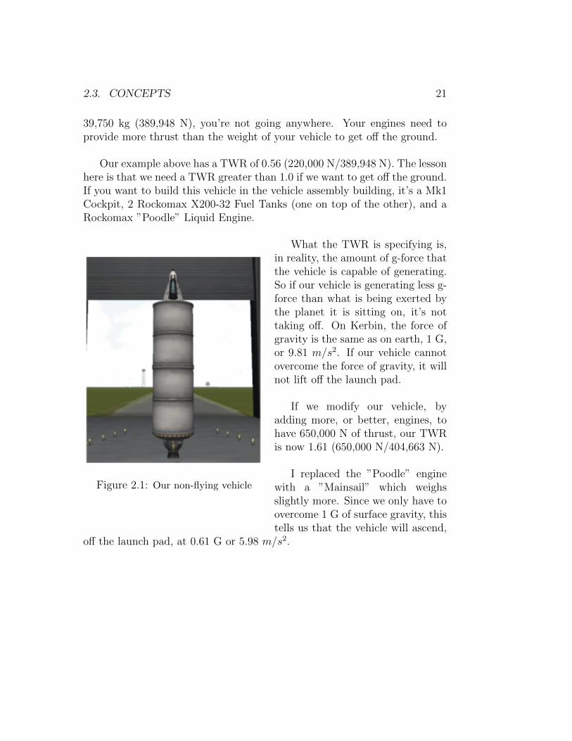
Our example above has a TWR of 0.56 (220,000 N/389,948 N). The lessonhere is that we need a TWR greater than 1.0 if we want to get off the ground.If you want to build this vehicle in the vehicle assembly building, it’s a Mk1Cockpit, 2 Rockomax X200-32 Fuel Tanks (one on top of the other), and aRockomax ”Poodle” Liquid Engine.
Figure 2.1: Our non-flying vehicle
What the TWR is specifying is,in reality, the amount of g-force thatthe vehicle is capable of generating.So if our vehicle is generating less g-force than what is being exerted bythe planet it is sitting on, it’s nottaking off. On Kerbin, the force ofgravity is the same as on earth, 1 G,or 9.81 m/s2. If our vehicle cannotovercome the force of gravity, it willnot lift off the launch pad.
If we modify our vehicle, byadding more, or better, engines, tohave 650,000 N of thrust, our TWRis now 1.61 (650,000 N/404,663 N).
I replaced the ”Poodle” enginewith a ”Mainsail” which weighsslightly more. Since we only have toovercome 1 G of surface gravity, thistells us that the vehicle will ascend,
off the launch pad, at 0.61 G or 5.98 m/s2.

22 CHAPTER 2. INTRODUCTION
Figure 2.2: Our modified vehicle (that
flies)
But, there are a couple of thingsthat happen to a rocket as itlaunches.
First off, as we discussed ear-lier, the vehicle loses mass VERYrapidly. As it loses mass, its weightgoes down, as its weight goes down,its TWR goes UP !
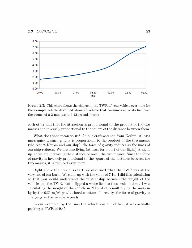
Example: We start with our ve-hicle that has 650,000 N of thrustand weighs 404,663 N. Let’s assume,for this example, that the vehicle is90,473 N of hardware and 313,920N (32,000 kg) of fuel (rememberthat the shuttle was only 5.8% shut-tle and 94.2% launch hardware andfuel).
Our launch TWR is 1.61, so welift off the launch pad at 5.98 m/s2.At 1 minute into the flight, we’veburned 39.4% of our fuel: 123,665
N (12,606 kg). So at the 1 minute mark our vehicle now weighs 280,998N (28,644 kg) but it still has the same thrust: 650,000 N. Our TWR at 1minute is: 2.31, so we are now accelerating a 1.31 Gs (12.85 m/s2).
At the 2 minute mark, we’ve burned 75.2% of our fuel and our vehiclenow weighs 168,506 N (17,177 kg), giving us a TWR of 3.86, or 2.86 Gs ofacceleration (28.06 m/s2).
The vehicle runs out of fuel at the 2 minutes and 42 second mark. Rightbefore it runs out of fuel, it weighs 90,752 N (9,251 kg), giving us a TWR of7.16, or 6.16 Gs of acceleration (60.43 m/s2)
The second important thing about TWR that we need to understand isthat, according to Newton’s Law of Universal Gravitation, masses attract
2.3. CONCEPTS 23
Figure 2.3: This chart shows the change in the TWR of your vehicle over time for
the example vehicle described above (a vehicle that consumes all of its fuel over
the course of a 2 minutes and 42 seconds burn)
each other and that the attraction is proportional to the product of the twomasses and inversely proportional to the square of the distance between them.
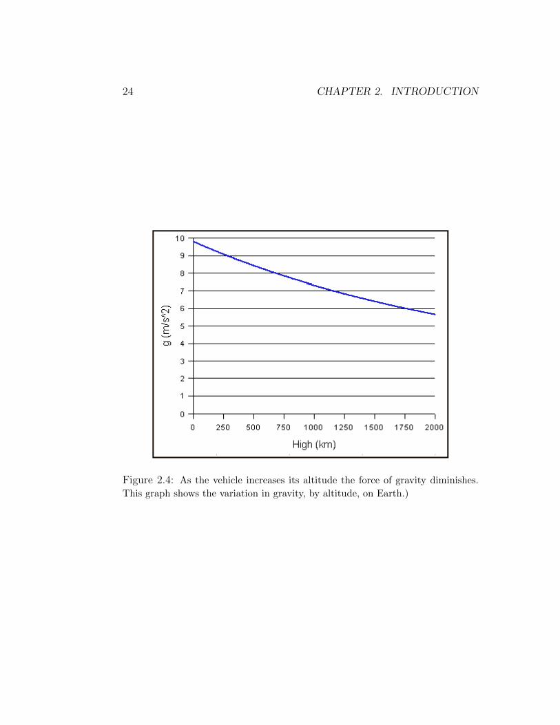
What does that mean to us? As our craft ascends from Kerbin, it losesmass quickly, since gravity is proportional to the product of the two masses(the planet Kerbin and our ship), the force of gravity reduces as the mass ofour ship reduces. We are also flying (at least for a part of our flight) straightup, so we are increasing the distance between the two masses. Since the forceof gravity is inversely proportional to the square of the distance between thetwo masses, it is reduced even more.
Right above the previous chart, we discussed what the TWR was at thevery end of our burn. We came up with the value of 7.16. I did this calculationso that you would understand the relationship between the weight of thevehicle and the TWR. But I slipped a white lie into those calculations. I wascalculating the weight of the vehicle in N by always multiplying the mass inkg by the 9.81 m/s2 gravitational constant. In reality, the force of gravity ischanging as the vehicle ascends.
In our example, by the time the vehicle ran out of fuel, it was actuallypacking a TWR of 9.45.
24 CHAPTER 2. INTRODUCTION
Figure 2.4: As the vehicle increases its altitude the force of gravity diminishes.
This graph shows the variation in gravity, by altitude, on Earth.)

2.3. CONCEPTS 25
To obtain information like ∆v, Isp and TWR for your vehicles, you caneither do the math, or use one of the various mods that provide that type ofinformation.
As of this writing the most popular mods that provide this type of infor-mation are: MechJeb and Kerbal Engineer Redux. More information aboutthese mods will be discussed in the chapter on Mods in a future volume.

26 CHAPTER 2. INTRODUCTION
2.3.4 Staging
As we saw above, mass is a big factor. The more mass we have to push withour engines (for a given Isp), the less ∆v we get out of our propellant. Theproblem here is that, in our day-to-day lives, we are not used to thinking ofthings in the scale necessary for astrodynamics.
In the Camaro example discussed, we carry 20 gallons of fuel that masses55 kg. What we didn’t mention was the mass of the fuel tank. I have no ideahow much a fuel tank for a Camaro would actually weigh, so let’s say 10 kg.Our Camaro’s mass, fueled, in total, is 1,775 kg. Of that total, 55 kg (fuel)plus 10 kg (fuel tank) is for our propellant. Only 0.56% of our vehicle is fueltank (fuel itself, if you remember, was 3.1%).
If we want to give our Camaro greater range, we could add another fueltank (+10 kg) and fill it with gas (+55 kg). So we add an additional 65 kg ofpropellant and hardware (the tank) bringing our total mass to 1,840 kg. Thisway we extend the range of our vehicle, at the cost of increasing its mass.That first tank of gas isn’t going to get us as far as it used to because now itis hauling the second, additional, tank of gas with it. And even after the firsttank is empty, the second tank will not take us as far as the single-tankedversion of our vehicle, because it is still hauling that extra 10 kg of empty(first) tank with it.
Ideally, once the first tank is empty, we drop it on the road, giving thesecond tank its full range (since after we’ve burned the fuel in the first tank,and dropped the empty first tank, our Camaro now masses 1,775 kg again).
That is what staging is all about, getting rid of mass that is no longerneeded: empty fuel tanks, dead engines (i.e. engines that have no morepropellant to burn), contingency hardware (i.e. the Launch Escape Systemthat sat on top of the Apollo command module in the Saturn V launchsystem), etc.
We tend to think ”Empty tank? Only 10 kg? Not worth the hardwarenecessary to detach and jettison those 10 kg. . . ”, but that is car based think-ing. In the shuttle’s case, the empty big orange tank has a mass of 26 tons.Each one of the empty, solid-rocket boosters on the shuttle has a mass of 91

2.3. CONCEPTS 27
tons. Remember that the shuttle itself (no external tank or boosters) has amass of 110 tons. So the ”dead weight” on the shuttle, after all propellant isconsumed, is 208 tons (26 tons + 91 tons + 91 tons). Almost TWICE themass of the orbiter itself!
The faster your vehicle sheds its dead mass, the more ∆v you will getfrom the engines and propellant that you still have, because there will beless mass to push.
Your vehicle design can, theoretically, have as many stages as you see fit.Just remember that each stage requires additional hardware (a decoupler ora separator, at a minimum), which is more mass that you have to push. Alsoremember that, at least in game, stage boundaries tend to be the weakeststructural points of your vessel. This means that you have to, typically, usestruts to strengthen the link so it can withstand the stresses of a launch andmaneuvers.
The shuttle is a 3 stage launch system:
1. At liftoff, all three main engines on the orbiter are burning (being fedfrom the external tank) and the solid rocket boosters are also burning.Once the SRBs have exhausted their propellant, they are jettisoned.That is the first stage, the 2 minutes between ignition on the launchpad and the decoupling of the SRBs.
2. During the second stage, the orbiter continues burning its main enginesusing fuel from the external tank. At this point (2 minutes into theflight), the external tank has only been 1
4depleted. So the second stage
will last, approximately, another 6 minutes. At this point, the externaltank is empty, so we get rid of it. That is the second stage, the 6minutes between SRB separation and external tank separation.
3. This is the final stage of the system and includes the orbiter alone.Its main engines are still attached to the vehicle, however they are nolonger used in the mission. In the real world, it is not an economicallysound proposition to jettison 3 $40 million pieces of hardware thatwould, presumably, be burned up and destroyed upon reentry. So theshuttle hauls 10.5 tons (3.5 tons per engine) of hardware around spaceand brings it back when it lands.
28 CHAPTER 2. INTRODUCTION
Fortunately for us, we don’t have (yet) congressional oversight committeesor politicians breathing down our necks in Kerbal Space Program, so feel freeto drop your ”Mainsail”s in the ocean or leave them in a degrading orbit onceyou no longer need them.
Just for completeness sake, I’m going to mention here the shuttle’s Or-bital Maneuvering System (OMS). Since once the orbiter is in orbit, it canno longer use the main engines, it needs some type of engine to do orbital in-jections, orbital corrections and deorbit burns. This is where the OM enginescome in. Fairly lightweight (100 kg) engines, that provide about 300 m/sof ∆v (it uses about 21.5 tons of propellant to provide that amount of ∆v).Bear in mind that this OM system is separate from the RCS system (thatwe know and love so much in Kerbal Space Program) used by the shuttle.We currently don’t have OM engines/tanks in KSP.
The strangest part about doing staging is that, in Kerbal Space Program,we have to build our vehicles from the top down. So if I were building a SaturnV equivalent, I would start with the Command Module (the capsule), wouldthen add the Service Module, the third stage, the second stage and finallythe first stage.
The basics of staging are as follows:
• To separate a stage, you should use a stack decoupler or a stack sep-arator. A stack decoupler/separator is the type that was used in theSaturn V. Once the first stage is depleted it separates from the rest ofthe vehicle by ”dropping off” of the stack above it.
• In Kerbal Space Program, fuel from tanks ”above” the stage bound-ary (above the decoupler/separator) will not feed ”through” the stageboundary to engines below the decoupler/separator.
• The various stack decouplers, and stack separators, have different ”de-coupling forces”. This means that they will push the separated stage(the one being discarded), away from the rest of the vehicle, with acertain force. In most cases, this force is negligible, since it is a ”small”force, typically, pushing a large piece of hardware. But in some cases,people use stack decouplers to ”launch” satellites from their main ve-hicle and don’t take that force into consideration and the satellite endsup in an orbit different from what they expected.

2.3. CONCEPTS 29
• It does not matter if you have ”struts” crossing the stage boundary,since the struts will ”automagically” disappear when the stack decou-pler/separator is triggered. You don’t have to worry about things notseparating because they are strutted to other things. Obviously, this isonly true in Kerbal Space Program. In real life, things would not workthis way (actually they could, but it wouldn’t be a simple ”strut”).
• If the part being separated (discarded) IS strutted across the stageboundary, the ”decoupling force” mentioned above, is affected by thestruts. Despite the fact that the struts DO ”break” upon triggeringthe decoupler/separator, it seems they absorb some of the force beingexerted by the decoupler/separator, resulting in the part being pushedaway from the vehicle with less force than if the part had NOT beenstrutted. This is true for both stack decouplers/separators and radialdecouplers/separators (see below).
• The difference between a stack decoupler and a stack separator is thatthe decoupler only severs the connection on one side (the side thatthe ”arrow”, printed on the side of the decoupler, points to) and thedecoupler will remain attached to the part being discarded. A stackseparator, on the other hand, severs the connection on both sides. Thismeans that with a separator, you end up with one vehicle, one discardedstage and a third part, the separator, floating freely around in spaceon its own.
• Radial Decouplers function just like stack decouplers, except they areused ”radially” (sideways/on the side). Think of the solid rocket boosterseparation on the space shuttle: they are pushed off to the side as theshuttle (and external tank) continues to move forward.
2.3.5 Attitude
From here on, you will start seeing the ”Attitude” a lot. For those of youfamiliar with the aerospace industry, this isn’t a problem, but for those ofus that are not familiar with it, I’m going to explain what is meant by”Attitude”.
From the Merriam-Webster, attitude is defined as:
30 CHAPTER 2. INTRODUCTION
the position of an aircraft or spacecraft determined by therelationship between its axes and a reference datum (such as thehorizon or a particular star)
So? Did that help?
Didn’t think so. . .
Here’s the problem: a spacecraft doesn’t act like any other terrestrialvehicle with which you might be familiar.
If you fire an engine in a spacecraft, that engine is going to push thatspacecraft in a particular direction. Once you turn the engine off, the space-craft will continue to move in that direction, at the same speed (i.e. inertia),unless something else influences that movement.
So. . . if you accelerate your spacecraft in a certain direction, and thendecide you want to stop moving in that direction, you have to ”turn around”and fire your engines again, to counteract the movement that you impartedon the vehicle when you fired them the first time.
So it’s real easy for me to sit here and type ”turn around”, but in spacehow do you determine which way is forwards (and therefore, which waysis backwards)? Compasses don’t work. . . there’s no ”north” (magnetic orotherwise). . . I guess you could use the stars for orientation, but what if theparticular celestial body you chose to use as guidance is no longer visible (onthe other side of the planet, for example)?
That’s what attitude is all about. . . rotating your vessel, using a myriadof different actuators, so that it is pointing in the direction that you need topoint to execute whatever maneuver you want.
The two main methods of adjusting attitude are discussed a little furtherbelow: RCS and SAS (or CMG, as it should really be called). Those are themechanisms that are used to change the attitude of you vessel, but how dowe figure out where we should be pointing?
The answer to that is the next section: Prograde/Retrograde. . .
2.3. CONCEPTS 31
2.3.6 Prograde/Retrograde
Prograde is nothing more than the current direction of travel for your vehicle.There is no magic involved. There are actual sensors on real spacecraft thatcan determine which direction your vehicle is moving.
In the game, the navball automatically shows you the information aboutprograde and retrograde, but that information IS available on real spacecraft.It might not be a pretty navball like the one we see in game (sometimes itis), but it’s there.
But how does knowing what direction I am traveling help me in any way?
Everything in space is about motion. If you want to slow down, youpoint in the direction opposite your direction of movement (retrograde) andfire your engines. If you want to speed up, you point in the same directionas your current direction of movement (prograde) and fire your engines. Ifyou want to change the inclination of your orbit, you point in a particulardirection, 90° from your current direction of movement, and fire your engines.And so on. . .
But why would I want to do any of those things? Speed up? Slow down?You just said if I’m moving in a certain direction, I’ll keep moving in thatdirection, at that speed. So what difference does it make if I’m going 1,000mph or 2,000 mph? Or 500 mph?
Because as we will see when we get to the Orbital Mechanics part of thisbook, how fast you are going (or not) determines exactly where you are, andwill stay (or not) in space. Remember what I said earlier, or even better,let’s look at Newton’s first law of motion:
When viewed in an inertial reference frame, an object eitherremains at rest or continues to move at a constant velocity, unlessacted upon by an external force.

32 CHAPTER 2. INTRODUCTION
One of the trickier words in there is ”velocity”. We tend to think of veloc-ity as ”speed”, but velocity is in reality a ”vector” quantity that representsboth speed and direction. We might apply a force to an object, like a space-craft, that doesn’t modify it’s speed, but modifies it’s direction, therefore weARE modifying it’s velocity.
But your question still is: ”I’m not firing my engines, I’m out in space,so there’s no ’external force’ acting upon my ship, so who cares?”
That’s where you are wrong. There ARE external forces acting on yourship. Dozens. . . hundreds. . . thousands of external forces acting on your shipALL THE TIME. Some to a great extent, some to a lesser extent.
Every single body, from the Sun and Jupiter, to the smallest of the aster-oids, are all exerting a gravitational force on your ship. Even stars light-yearsaway are exerting, however minute, gravitational forces on your ship! Thinkabout it, it is gravity that maintains the solar system in it’s current configu-ration, the same way that it is gravity that maintains the Milky Way galaxyin it’s current configuration!
All those teeny, tiny little gravitational forces combine to affect your ship,and every other body in the universe.
In most cases, we can ”ignore” a lot of these forces, because of how smallthey are. Typically, you are under the influence of a ”main” body, whichexerts a significant portion of the forces being applied to your ship. In reallife we can’t ignore ALL of the forces except the ”main” one, but becauseof limitations in the capability of your computer to process these hugelycomplex calculations, in Kerbal Space Program, only ONE body ever exertsforce on your ship at a time.
But back to prograde/retrograde. . .
Knowing which direction you are moving (prograde) is EXTREMELYimportant, because knowing that one direction, you can figure out all of theother directions that you will need to know to perform any maneuver.
2.3. CONCEPTS 33
2.3.7 RCS - Reaction Control System
Now that we understand what attitude of the vehicle means, let’s see whatwe use to adjust attitude. There are two different systems to adjust attitude.The first of these systems is the Reaction Control System.
Most liquid fueled engines, in real life, have very limited duty-cycles (howmany times they can be ”fired” without requiring a rebuild/refurbishing).For example, the space shuttle main engines, the 3 big ones on the back ofthe shuttle, are refurbished after every flight. They light up, once, duringlaunch, and burn until their fuel is exhausted. They then return to Earthwith the shuttle and are refurbished before being fired again.
The shuttle’s OMS (Orbital Maneuvering System) engines, on the otherhand, are built to be fired multiple times between refurbishings.
An interesting scene to watch, in the movie Apollo 13, is the scene wherethe astronauts are tasked with firing the lunar module’s engine for a secondtime for a course correction. The representative, on screen, of the manufac-turer of the engine (Grumman, I think) makes a comment along the linesof ”it wasn’t built to do this!” and the relief, after the successful firing isclearly visible on his face! This is exactly because the engine was designed tofire during the landing, and burn continuously until they reached the surfaceof the moon and stay behind when the ascent engine was used to return toorbit. It was never designed to be fired more than once.
RCS thrusters, on the other hand are designed to be fired hundreds (ifnot thousands) of times, before needing to be rebuilt or refurbished. Theyprovide very small amounts of thrust, compared to the SSME or even theOMS engines, but are more than sufficient to provide the necessary thrust forvarious types of maneuvers. These maneuvers include, but are not limitedto:
• attitude control during re-entry
• station keeping (small maneuvers performed by orbiting craft to main-tain its position in space since most orbits degrade slightly over longperiods of time)

34 CHAPTER 2. INTRODUCTION
• docking maneuvers, that require multiple, very small, adjustments tocomplete
• orientation, pointing the vehicle in a specific direction
• deorbiting, in extreme situations, if the craft has lost its ability todeorbit due to a malfunction of the OMS engines or equivalent
In KSP, the RCS thrusters require a specific type of fuel, monopropellant,that you must provide for in your craft design.
There are also two different types of RCS thrusters in game: the RCSblock, which is a multi-directional thruster that can provide comprehensivemaneuvering capability to a craft; and the Linear RCS thruster, which pro-vides thrust in a single direction.
The placement of the RCS thrusters on your vehicle is of paramountimportance if you intend to do precise maneuvers such as docking. Also, ifyour craft is very large, multiple banks of RCS thrusters might be necessary,otherwise the craft will be ”sluggish” to respond to your maneuvers (whichmay be fine if you are the patient type). In the future I will go into moredetail regarding RCS positioning and usage within the game.
2.3.8 SAS - Stability Augmentation System
The actual definition of what is an SAS system is a system that uses devicesto STABILIZE the flight of a vehicle. The terminology in Kerbal SpaceProgram gets confusing when they talk about capsules, cockpits and probeshaving SAS Torque. The SAS parts in Kerbal Space Program do indeedstabilize the vehicle, but the torque provided by the capsules/probes is NOTSAS torque. The torque generated by the capsules/probes is more aptlydescribed as CMG (Control Moment Gyroscope) torque.
SAS (Inline Advanced Stabilizer, Inline Reaction Wheel and AdvancedSAS) can be used on your vehicles to reduce the vehicle’s tendency to ”wan-der” during flight. Most rockets will have some tendency to ”pull” to one
2.4. ORBITAL MECHANICS - THE ”MATHY” PART 35
side, or to rotate along it’s axis, etc., unless it is perfectly symmetrical. Onceatmospheric drag is implemented in the game in a proper fashion, this ten-dency will most likely increase since, even the positioning of a part, such asa strut, will affect how the vehicle reacts to the atmosphere.
The dampening effect of an SAS unit can be increased by placing multipleunits on your vehicles.
Placement of the SAS units will determine how effective they are in damp-ening any movement. An example of this would be a short, wide vehicle,where a significant amount of mass is ”around” the center of mass, and notlined up with the center of thrust (i.e. asparagus staging). If you were toplace a single SAS unit along the center of thrust (i.e. on the nose of thecapsule), it would not be able to, efficiently, counter movement imparted bythe mass ”outside” of the center of thrust. It will work, just not as well. Asolution in a case like this would be to place additional SAS units, in ourasparagus staging case, on top of each stack in the asparagus ”bunch”.
2.4 Orbital Mechanics - The ”Mathy” part
2.4.1 What is an Orbit?
An orbit is the ”gravitationally curved path of an object around a pointin space”. This means that you are constantly falling toward that point inspace, but you never reach it because your horizontal velocity pushes youaway as you are falling.
An example: a spacecraft in orbit around the Earth. The craft is con-stantly falling, however it is moving VERY fast horizontally, so as it fallsit ”misses” the Earth, passing beyond the horizon and continues falling. Itis because of this ”falling” that astronauts experience weightlessness. Theyare not weightless, but in relation to the vehicle that they are in, they feelweightless. They are, in reality, free falling around the planet.
36 CHAPTER 2. INTRODUCTION
When I say VERY fast above, I mean VERY FAST! Orbital velocity forEarth, in a low Earth orbit (200 - 2,000 km altitude) is somewhere between15,400 and 17,400 mph!
But what we are going to discuss here are some components of an orbit soyou can understand the terminology that you will see in game, on the wiki,in the forums and other places where Kerbal Space Program is discussed.
Apsides
An apsis (plural: apsides) is the point of greatest or least distance of a bodyfrom one of the foci of an elliptical orbit. In Kerbal Space Program, we areacquainted with two of the apsides: periapsis and apoapsis. The referencefocus, in our situation, is always the body that we are orbiting.
2.4.2 Periapsis
The periapsis of your orbit is the point in the orbit at which you will be atthe least distance from the body you are orbiting. It is your closest approachto the body being orbited.
When we discuss orbital maneuvers, you will see why it is important toknow where this point of your orbit is located. Certain orbital maneuverswork especially well when performed at specific points in your orbit.
Another important use for the periapsis is that, since it is the lowest pointin your orbit, you can tell whether your orbit will degrade due to atmosphericeffects. If at the lowest point in your orbit you are still above the atmosphereof the body you are orbiting (for Kerbin: ∼70km), then you know that yourorbit is ”stable” since you will not encounter any atmospheric effects at anypoint in your orbit. You could, theoretically, leave your craft in that orbit,indefinitely, and it would never fall back to the body it is orbiting.
Obviously, the previous paragraph only applies to bodies that have atmo-spheres. But even the bodies that don’t have atmospheres have a minimum
2.4. ORBITAL MECHANICS - THE ”MATHY” PART 37
periapsis of which you should be mindful. For example, on the Mun thehighest mountain peak is 3,340 meters; on Minmus, 5,725 meters; and onGilly, 6,400 meters. If you are establishing an orbit around any body, makesure you verify the highest elevation of that planet/moon, unless you wantto plow into the face of a mountain.
All elevations, including the periapsis and apoapsis, in game are expressedin relation to sea level of the reference body.
According to Kepler’s Second Law of Planetary Motion:
”A line joining a planet and the Sun sweeps out equal areasduring equal intervals of time”
If we substitute ”planet” with ”vessel” and ”Sun” with ”orbited body”,the law still applies, since physical laws are not exclusive to stars and planets.We now have:
”A line joining a vessel and the orbited body sweeps out equalareas during equal intervals of time”
What this implies is that the vessel’s velocity is higher when it is closerto the orbited body, hence lower when it is farther away. Since the periapsisis the closest the vessel can come to the orbited body (in a given orbit), it isalso the point in the orbit where the vessel has it’s highest velocity.
In Kerbal Space Program, the periapsis of your orbit is indicated, whilein map view, by a little blue marker with a ”Pe” inside of it. Below is apicture of what that looks like:

38 CHAPTER 2. INTRODUCTION
If you hold your mouse over the ”Pe” marker, it will show you the altitudeof your periapsis:
Additionally, if you click on the little marker, it will stay showing theperiapsis altitude even if you move your mouse elsewhere. It is kind of trickyto click on the marker and not on the orbit at the same time, because whenyou click on the orbit, you get the popup asking you if you want to ”AddManeuver”.
2.4. ORBITAL MECHANICS - THE ”MATHY” PART 39
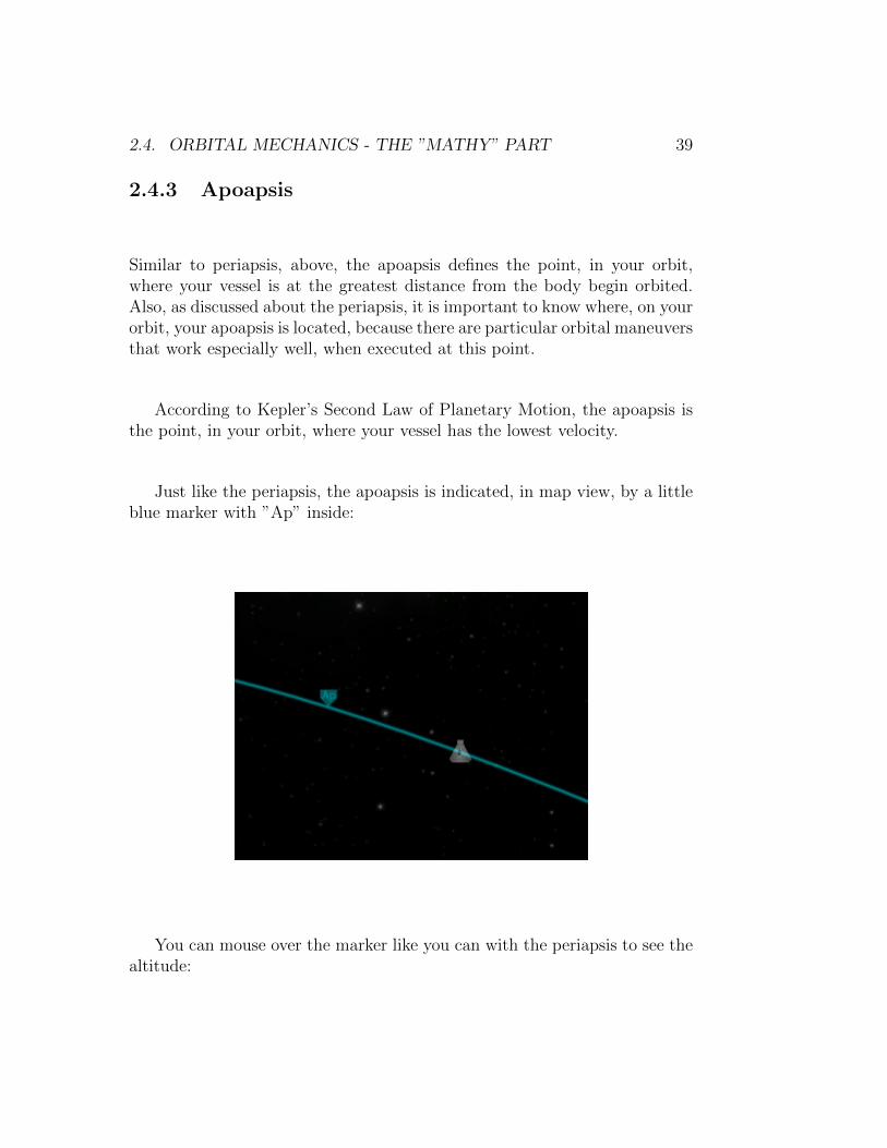
2.4.3 Apoapsis
Similar to periapsis, above, the apoapsis defines the point, in your orbit,where your vessel is at the greatest distance from the body begin orbited.Also, as discussed about the periapsis, it is important to know where, on yourorbit, your apoapsis is located, because there are particular orbital maneuversthat work especially well, when executed at this point.
According to Kepler’s Second Law of Planetary Motion, the apoapsis isthe point, in your orbit, where your vessel has the lowest velocity.
Just like the periapsis, the apoapsis is indicated, in map view, by a littleblue marker with ”Ap” inside:
You can mouse over the marker like you can with the periapsis to see thealtitude:
40 CHAPTER 2. INTRODUCTION
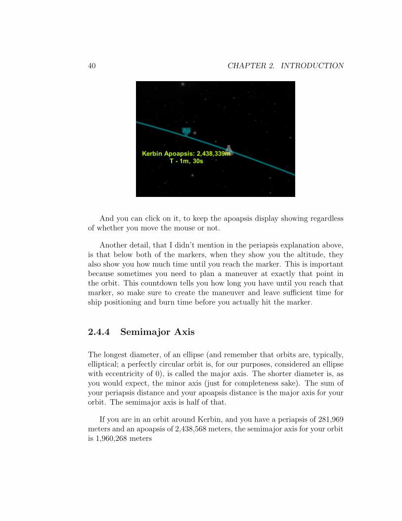
And you can click on it, to keep the apoapsis display showing regardlessof whether you move the mouse or not.
Another detail, that I didn’t mention in the periapsis explanation above,is that below both of the markers, when they show you the altitude, theyalso show you how much time until you reach the marker. This is importantbecause sometimes you need to plan a maneuver at exactly that point inthe orbit. This countdown tells you how long you have until you reach thatmarker, so make sure to create the maneuver and leave sufficient time forship positioning and burn time before you actually hit the marker.
2.4.4 Semimajor Axis
The longest diameter, of an ellipse (and remember that orbits are, typically,elliptical; a perfectly circular orbit is, for our purposes, considered an ellipsewith eccentricity of 0), is called the major axis. The shorter diameter is, asyou would expect, the minor axis (just for completeness sake). The sum ofyour periapsis distance and your apoapsis distance is the major axis for yourorbit. The semimajor axis is half of that.
If you are in an orbit around Kerbin, and you have a periapsis of 281,969meters and an apoapsis of 2,438,568 meters, the semimajor axis for your orbitis 1,960,268 meters
2.4. ORBITAL MECHANICS - THE ”MATHY” PART 41
(281,969+600,000)+(2,438,568+600,000)2
(The 600,000 in the equation above is the radius of the planet Kerbin.In calculating the semimajor axis, we count the distance to the center of thebody being orbited. Since periapsis and apoapsis are both given as an altitudefrom sea level, we need to add the radius of the planet for our calculations.)
The closer your orbit is to a perfect circle, the closer the semimajor axiswill be to the radius of your orbit (in a perfect circle, the semimajor axis ISthe radius).
The semimajor axis is important to determine the orbital period of yourorbit (how long it takes for your vessel to complete one orbit).
The formula is:
T = 2π√√√√a3
µ
where:
• a = the length of the semimajor axis of the orbit (in meters)
• µ = the standard gravitational parameter of the body you are orbiting
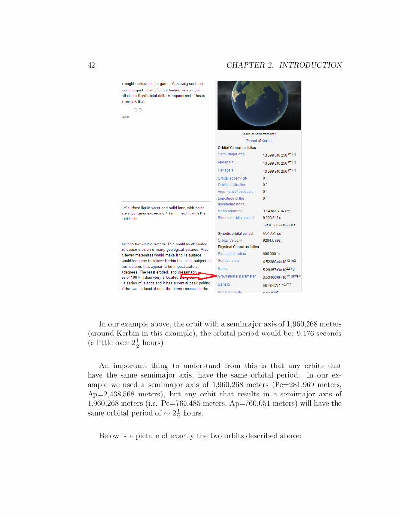
When performing the calculation, if you are so inclined, remember touse meters and not kilometers for the semimajor axis. The gravitationalparameter for the various bodies in the Kerbol System can be found in theKerbal Space Program Wiki. In the description of each body in the system,you can find the gravitational parameter listed as shown in the screenshotbelow:
42 CHAPTER 2. INTRODUCTION
In our example above, the orbit with a semimajor axis of 1,960,268 meters(around Kerbin in this example), the orbital period would be: 9,176 seconds(a little over 21
2hours)
An important thing to understand from this is that any orbits thathave the same semimajor axis, have the same orbital period. In our ex-ample we used a semimajor axis of 1,960,268 meters (Pe=281,969 meters,Ap=2,438,568 meters), but any orbit that results in a semimajor axis of1,960,268 meters (i.e. Pe=760,485 meters, Ap=760,051 meters) will have thesame orbital period of ∼ 21
2hours.
Below is a picture of exactly the two orbits described above:

2.4. ORBITAL MECHANICS - THE ”MATHY” PART 43
The blue orbit is almost perfectly circular, with a periapsis of 760,051meters and an apoapsis of 760,485 meters. The gray orbit has a periapsis of281,969 meters and an apoapsis of 2,438,568 meters and is visibly elliptical.Both of these ships take the exact same time to complete one full orbit: the∼ 21
2hours I calculated above.
2.4.5 Eccentricity
Eccentricity of an orbit describes how elliptic an orbit is, compared to aperfect circle. A perfectly circular orbit is an orbit where the vehicle is at aconstant reference altitude, in every point of its orbit.
Perfectly circular orbits are uncommon. Most orbits are, at least, slightlyelliptical in nature.
44 CHAPTER 2. INTRODUCTION
In Kerbal Space Program, Kerbin, and both of its moons, have perfectlycircular orbits (the former around the Sun, the latter around Kerbin itself).Duna, on the other hand has an orbital eccentricity of 0.05. This indicatesthat its orbit is slightly elliptical. Eeloo has an eccentricity of 0.26, whichmeans its orbit is much more elliptical than Duna’s. If you use the map modein Kerbal Space Program and zoom WAY out, you will see how the shapesof the orbits of the different planets vary.
In real life, the eccentricity varies from 0.00677 (for Venus) on the lowend, to 0.20563 (for Mercury) on the high end (for planets, not going intothe realm of dwarf planets, comets, asteroids, etc.).
In the last picture shown in ”Semimajor Axis” above, I show two orbits.The blue one is an (almost) perfect circle, therefore it has an eccentricity of0. The grey orbit is visibly elliptical (what us common folk call an oval) andhas an eccentricity of 0.55.
2.4.6 Inclination
Inclination describes how inclined an orbit is. To have an inclination (anangle in degrees), you need some type of reference point. In the case oforbital inclinations, we use what is called the ecliptic plane.
Draw the Sun on a sheet of paper, then draw the Earth’s orbit around theSun. That gives you a roughly circular orbit. Now take that page and look atit sideways, that is the ecliptic plane. So if another planet in the system hasan inclination of 60 degrees (very unusual, but useful for our understanding),that means that if you were to draw its orbit on another sheet of paper, thenyou would combine the two sheets at an angle of 60 degrees.

2.4. ORBITAL MECHANICS - THE ”MATHY” PART 45
Most inclinations are given with relation to a specific body. In our solarsystem, Earth is the reference body, therefore Earth’s orbit has an inclinationof zero degrees in relation to the ecliptic plane (since Earth’s orbit DEFINESthe ecliptic plane, it couldn’t be any other way).
The planets of Earth’s solar system, do not all orbit on the same plane,they have various different inclinations. The same is true of Kerbin’s solarsystem. In Kerbin’s system, the planet that has the closest inclination toKerbin’s orbit is Duna, at 0.06 degrees.
Inclination is important because, when you are planning encounters, if thetarget is on a different plane, then you have to correct for the inclination ofthe target, otherwise you will pass the target’s orbit with the target ”above”or ”below” you.
This is a picture, from in game, of two vessels orbiting Kerbin. Both ofthese vessels are orbiting at an altitude of 100,000 meters:
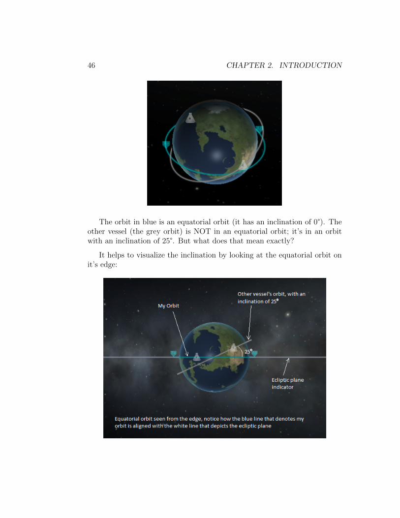
46 CHAPTER 2. INTRODUCTION
The orbit in blue is an equatorial orbit (it has an inclination of 0°). Theother vessel (the grey orbit) is NOT in an equatorial orbit; it’s in an orbitwith an inclination of 25°. But what does that mean exactly?
It helps to visualize the inclination by looking at the equatorial orbit onit’s edge:

2.4. ORBITAL MECHANICS - THE ”MATHY” PART 47
When looking at the equatorial orbit on its edge, it shows as a straightline. As an extra bonus, this shot also shows the ecliptic plane. As you cansee, the other vessel’s orbit, when seen edge on, creates an angle betweenitself and the ecliptic plane. That angle is 25°, and that is why we say theorbit has an inclination of 25°. In our example above, we happen to also havea vessel whose orbit is aligned with the ecliptic plane, but it’s the eclipticplane reference that defines the inclination angle.
2.4.7 LAN - Longitude of Ascending Node
When an orbit is inclined to the ecliptic plane (has an inclination differentthan 0°), there will be two points, in that orbit, where the orbit crosses theecliptic plane. At one of those points it will be below the ecliptic plane andwill be crossing the plane to above the ecliptic plane. It will be ”ascending”.So that point will be the ascending node, the other point (where it’s crossingthe ecliptic from above to below), is the descending node.
So what’s this business with the longitude?
The orbit will cross the ecliptic plane at a specific point. Imagine thatyou were looking out from the ship at this point, and looking straight downat the planet you are orbiting. You would be looking at a specific point onthe planet (let’s say, in the case of the Earth, you happened to be lookingdown at Tokyo). Tokyo’s longitude is approximately 140° E. So the LAN(longitude of ascending node) would be 140°.
What this defines is the location of the periapsis and apoapsis of the orbitin relation to the prime meridian (in our case, 140° is relative to the primemeridian of the Earth).
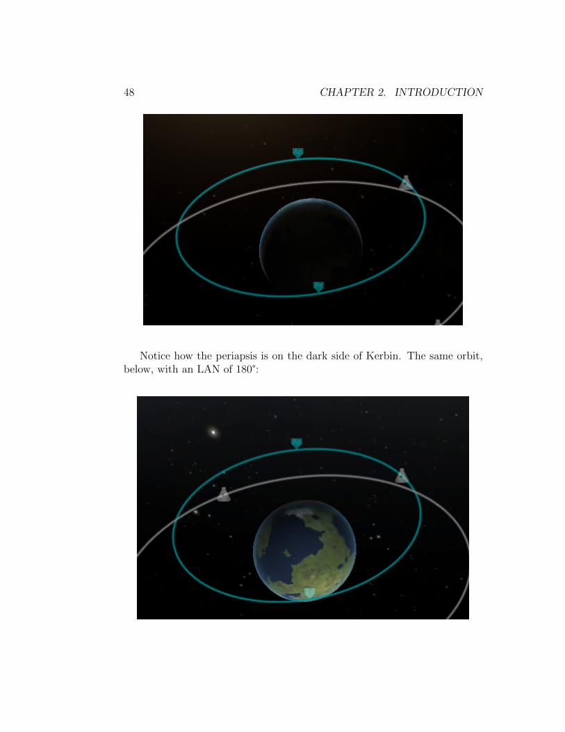
The picture below shows an elliptical orbit (the same one from our pre-vious topics), with an LAN of 0°:
48 CHAPTER 2. INTRODUCTION
Notice how the periapsis is on the dark side of Kerbin. The same orbit,below, with an LAN of 180°:
2.4. ORBITAL MECHANICS - THE ”MATHY” PART 49
Notice how, now, the periapsis is on the light side of Kerbin. The orbit is”rotated” 180° in relation to the orbit that had an LAN of 0°. All the otherparameters of the orbit remain the same: periapsis, apoapsis, semimajor axis,eccentricity, inclination, etc.
With an orbit that is elliptical, we have two main points: the periapsisand the apoapsis. The LAN defines, indirectly, where those two points are inthe orbit, in relation to a longitude system defined for the body it is orbiting.
Now you might say, ”but Mars (or Duna, for that matter) doesn’t haveany ’defined’ longitude system!”. Well, you’re right, kinda.
We, humans, self-centered creatures that we are, defined OUR longitudesystem in relation to the prime meridian. Over the millennia, the primemeridian has varied in location (the place we call longitude 0°), until finally,in 1884, we as a species, decided we needed one standard. We elected theGreenwich Meridian to be THE Prime Meridian and it has been ever since.
Even so, that is not the prime meridian that we use when defining theLAN of orbits. The prime meridian for orbital parameters is called the originof longitude. For Earth-based LANs (and any heliocentric orbits) we use theFirst Point of Aries.
The First Point of Aries has been the origin of longitude for a very longtime. It is still used as the origin even though, due to the precession of theequinoxes, the point is no longer in the constellation of Aries.
For bodies outside of the Earth solar system, another prime meridian isdetermined by a method WAY too complicated to explain here, and anglesare measured from that meridian. For our purposes, the LAN has a referencemeridian, in the Kerbol system, that is used to calculate the LAN.
For orbits that have an inclination of 0°, the orbit never actually crossesthe reference plane (it is not inclined in reference to that plane, hence theinclination of 0°), it is established that the LAN is also placed at 0° longitude.

50 CHAPTER 2. INTRODUCTION
2.4.8 Argument of Periapsis (ω)
The argument of periapsis, typically symbolized by ”ω”, is the angle betweenthe longitude of the ascending node and the periapsis of the orbit. Addingthe argument of periapsis to the longitude of the ascending node gives usanother parameter: the longitude of periapsis. However, in many circles theterms ”longitude of periapsis” and ”longitude of periastron” are often usedas synonyms to ”argument of periapsis”.
So it is a parameter, in the strict sense, but probably nothing that weneed to worry about in the game.
2.4.9 Mean Anomaly
The mean anomaly of an orbit is a parameter relating position and time fora body in a Kepler orbit.
Kepler’s law stipulates that the line connecting the orbiting body to thefocus of its orbit sweeps equal areas in equal times during its orbit.
The mean anomaly can vary from 0 to 2π radians. But it is not an angle.It is proportional to the area swept, by the line connecting the orbiting bodyand the focus of the orbit, since the last periapsis.
It is kind of an indicator as to how far, past the periapsis, the orbitingbody is in its journey around the orbit.
Most of the parameters that we have seen up until this point have beenparameters that describe the orbit as a whole: how high it is at differentpoints (periapsis and apoapsis), how inclined it is in relation to the eclipticplane (the inclination), how oval or round it is (the eccentricity), where theorbit crosses the plane when it is inclined (the longitude of ascending node)and where the periapsis is in relation to the LAN (the argument of periapsis).
The one thing that we have not described until now is: Where is theorbiting body, on this elliptic orbit that we so painstakingly defined, rightnow? That’s what the mean anomaly does.
This concludes the section about orbital parameters. Below is a graphthat illustrates SOME of the concepts explained so far:

2.4. ORBITAL MECHANICS - THE ”MATHY” PART 51
2.4.10 Orbital Stability
I’ve mentioned ”stable” orbits a couple of times so far. But what is a stableorbit? A stable orbit is an orbit that will not degrade over long(ish) periodsof time. In real life, a stable orbit is very hard to achieve. There are just toomany factors that play into the stability of an orbit for it to be considered100% stable.
The International Space Station (ISS), with an orbital periapsis of 330 km,is still subjected to drag from Earth’s upper atmosphere. This drag causesthe station to slowly lose altitude, over time, which makes it necessary to
52 CHAPTER 2. INTRODUCTION
fire engines on the station to correct it’s altitude. But there are other factorsthat contribute to the lack of orbital stability for any body orbiting another.
All of the bodies in the Solar System exert some influence, howeverminute, on every other body. This means that even if the ISS was com-pletely free of the atmosphere, the gravitational pull of the Moon, the Sun,Jupiter, and even tiny little Mercury are all influencing it’s orbit.
By far, the Earth, being the body that is closest to the ISS AND thebody around which the ISS revolves, has the greatest influence on the ISS’sorbit. But it’s orbit will change, very slightly, over long periods of time, dueto these other influences.
But enough about real-life, it’s depressing.
In Kerbal Space Program, things aren’t quite like that. This whole busi-ness of calculating all the little, teeny tiny influences of multiple bodies uponeach other is what is known, in the astrophysics community, as the n-bodyproblem. There is no exact solution to the n-body problem for n ¿ 2. Forany system, that needs to be analyzed, that contains more than 2 bodies,the best we can do is an approximation, and even that takes A LOT of work.Much more than our measly little desktop computers are capable of in anyrealistic timeframe that would make the game still playable.
So, we are limited, by the physics engine used in the game, to 2 bodies.So if a ship is orbiting Kerbin, Kerbin is one body and the ship is the other.The game’s physics engine doesn’t take into consideration any other bodieswithin the system that might be influencing the ship’s orbit. This makesorbits that we establish, in game, more stable than they would be otherwise.So in game we don’t have to worry about all the other bodies in the systeminfluencing our vessels’ orbits.
This however, has some drawbacks. To be able to have transfers fromone body (i.e. Kerbin) to another body (i.e. the Mun), at some point thesystem has to stop considering Kerbin our first body and switch over to theMun (our ship is the second body in both cases). This is resolved by what iscalled Spheres of Influence (usually abbreviated as SOI or SoI). Kerbin hasa specific SOI that extends from Kerbin’s surface to a specific height. Every

2.4. ORBITAL MECHANICS - THE ”MATHY” PART 53
other body in the system, similarly, have their own SOIs defined. Once yourvessel leaves Kerbin’s SOI it is shifted to another SOI. If your ship is notnear enough to another body, to be within that body’s SOI, then the SOI ofKerbol (the game’s ”Sun”) is used.
Below is a screenshot of a typical Mun transfer:
In this picture, the blue orbit is your orbit, within Kerbin’s SOI, the littlecircle at the point where the blue transitions to the yellowish line is what iscalled a ”Mun encounter”. Once we cross that point in the orbit, we are nolonger within Kerbin’s SOI, we are then in the Mun’s SOI.
The yellow orbit, further along, transitions to the purple orbit, the littlecircle on the threshold identifies it as ”Mun Escape”. This means that left to
54 CHAPTER 2. INTRODUCTION
its own devices, the ship will transition into the Mun’s SOI and continue onuntil it leaves the Mun’s SOI and transitions back, in this particular case, toKerbin’s SOI. If I let it go even further along this trajectory, it exits Kerbin’sSOI and transitions to Kerbol’s (the Sun’s) SOI and establishes itself in anorbit very similar to Kerbin’s own orbit around the Sun.
These spheres of influence are what allow the game’s physics engine toresolve the 2 body problem. Any given vessel is only, ever, in one sphere ofinfluence at any given time.
But the 2 body physics limitation also causes a problem with. . .
2.4.11 Lagrange Points
Lagrange points are, in astrophysics, defined points, near two bodies, wherea 3rd body (and herein lies the problem) can maintain a consistent position.The calculations of these points requires some intense mathematics that thegame’s physics engine is not capable of executing within a timeframe thatwould make the game playable.
Essentially, a body can position itself at one of these Lagrange points(there are five) and remain in a constant position, in relation to the othertwo bodies.
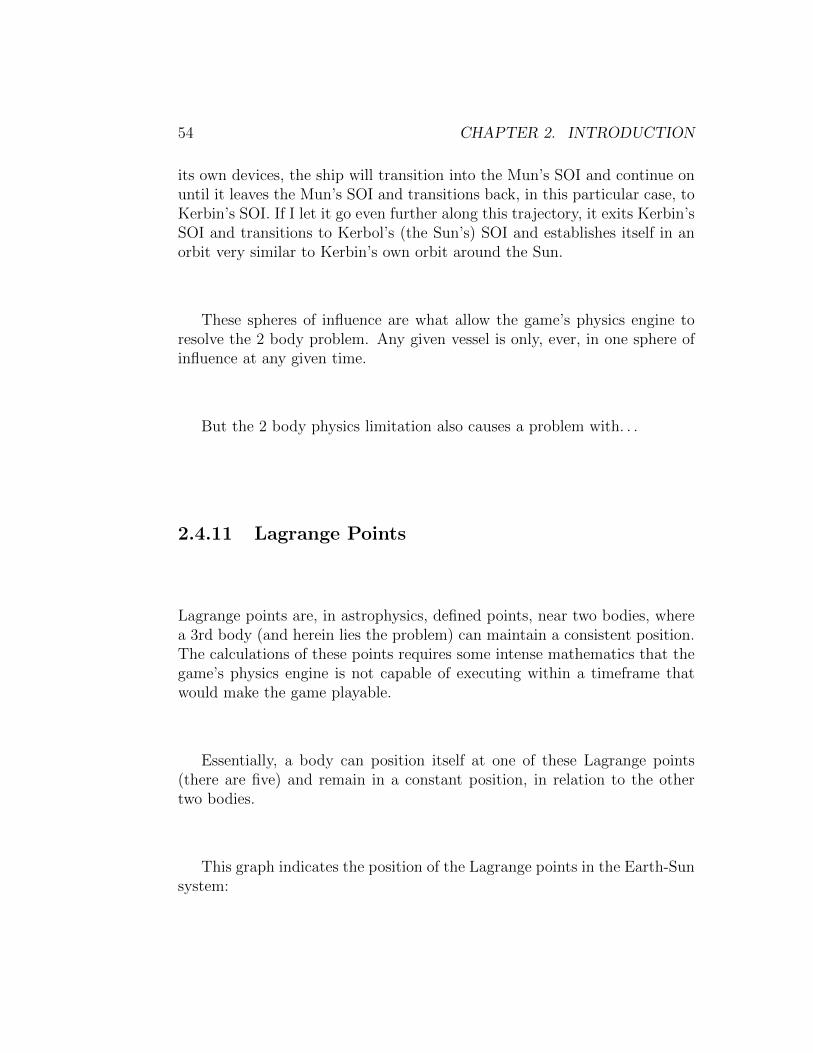
This graph indicates the position of the Lagrange points in the Earth-Sunsystem:

2.4. ORBITAL MECHANICS - THE ”MATHY” PART 55
At L1, the body is stable. The pull from the Sun’s gravity, and the pullfrom Earth’s gravity, ”drag” the body around the Sun in the same exactamount of time as the Earth takes to orbit the Sun (which is odd, as we’llsee in a bit). L1 is the most ”intuitive” of the Lagrange points: it makes”sense”; the body is being ”wrestled” by the other two bodies’ gravitationalforces, therefore doesn’t quite react as it should.
The other four Lagrange point are less ”intuitive”, but they exist nonethe-less. Any object placed at those points, will remain in that exact same,relative spot (not so much a spot, in the case of L4 and L5, as an area).
But why ”should” they react any differently?
56 CHAPTER 2. INTRODUCTION
2.4.12 Altitude vs. Velocity
In any orbit, the semimajor axis (so indirectly, the periapsis and the apoapsis)defines the orbital period.
An orbit with a semimajor axis of X has an orbital period smaller than anorbit with a semimajor axis of 2X. I’m not going to go into the mathematicsand give you numbers, just accept that it is true. Crunch the numbers if youdon’t believe me.
If I am orbiting Kerbin at 100 km, I am moving faster than another shipthat is orbiting Kerbin at 200 km. If the ship at 200 km takes X amount oftime to complete one full orbit, my ship will complete one full orbit in somefraction of X amount of time. So for every orbit that the 200 km ship makesI make more than one orbit at 100 km. Effectively, I’m ”pulling ahead” ofthe other ship.
If I were to raise my orbit to 300 km, then I would be the one movingslower than the one at 200 km and it would pull ahead of me (or catch up,if it were already behind).
The further the ships are from the center of mass they are orbiting, theslower they move to maintain that orbit (I’m assuming all circular orbitshere, just for sanity’s sake).
We discussed the same concept when we were discussing periapsis andeccentricity. As I approach my periapsis (in a non-circular orbit), I gainvelocity (because I’m closer to the planet). When I reach my periapsis, I amat the closest point I will ”ever” be to the planet, so I am also as fast asI’m going to get in this orbit. As I pass the periapsis and head toward theapoapsis (gradually getting further from the planet), my velocity decreasesuntil I reach the apoapsis (furthest point, lowest velocity) and start headingback to the periapsis again to begin the next cycle.
This is what is ”odd” about bodies at Lagrange points. If a body is atthe L1 point, it is, by definition, closer to the Sun than the Earth is, so itshould be moving faster than the Earth, pulling ahead of the Earth in itsorbit. However, it doesn’t. Because of the interaction between the Sun’s
2.4. ORBITAL MECHANICS - THE ”MATHY” PART 57
gravity and the Earth’s gravity, the body moves as fast as the Earth doesaround the Sun, effectively maintaining its position with relation to both theSun and the Earth.
I think this information might come in handy later, in something called”rendezvous”, so keep it in a safe place.
2.4.13 Oberth Effect
As we learned in high school physics, objects in motion have kinetic energy.Kinetic energy is best described as the energy the object gained by beingaccelerated to its current speed.
The Oberth Effect, after Austro-Hungarian-born physicist Hermann Oberth,describes how a vehicle employs it’s kinetic energy to generate more mechan-ical power, resulting in more usable energy, by the application of an impulse,usually provided by a rocket engine, while in close proximity to a gravita-tional body.
If we skip all the math and get right down to the meat of the matter,what this means to us, in Kerbal Space Program, is that:
The same amount of thrust expended (∆v), at a given point in our orbitwill result in a final velocity (at distance) to be much larger than expected,depending on where in that orbit the burn occurs.
In a previous section, I mentioned that knowing where the periapsis andthe apoapsis of your orbit is important, because certain maneuvers workespecially well when executed at exactly those points. The Oberth maneuveris one of those maneuvers that works especially well when executed at theperiapsis of your orbit.
Imagine an elliptical orbit around Kerbin, with a periapsis of 100,000meters and an apoapsis of 300,000 meters.

58 CHAPTER 2. INTRODUCTION
Your vehicle is moving its fastest when it is at the periapsis and its slowestwhen at the apoapsis. Those speeds, for this orbit are: at your periapsis youare moving at 2,383 m/s. At your apoapsis, you will be moving at 1,853m/s.
If we now create a maneuver, at our periapsis, where we expend 100 m/sof ∆v, this is what our maneuver would look like:

2.4. ORBITAL MECHANICS - THE ”MATHY” PART 59
Our apoapsis was raised to 498,000 meters (an increase of 200,000 meters),and our periapsis remains the same. The velocities at both points are now:2,483 m/s at the periapsis (what it was + 100 m/s), but our velocity at theapoapsis has changed to 1,581 m/s.
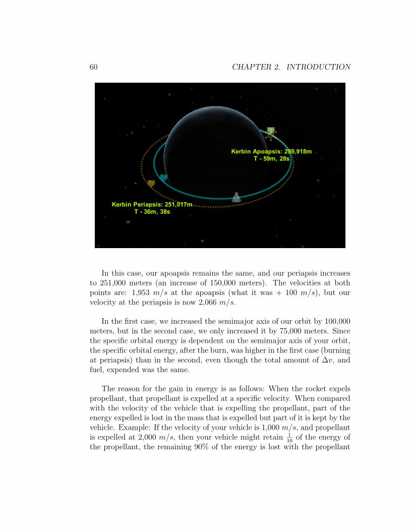
If we do the maneuver, the same 100 m/s increase, at the apoapsis, themaneuver looks like this:
60 CHAPTER 2. INTRODUCTION
In this case, our apoapsis remains the same, and our periapsis increasesto 251,000 meters (an increase of 150,000 meters). The velocities at bothpoints are: 1,953 m/s at the apoapsis (what it was + 100 m/s), but ourvelocity at the periapsis is now 2,066 m/s.
In the first case, we increased the semimajor axis of our orbit by 100,000meters, but in the second case, we only increased it by 75,000 meters. Sincethe specific orbital energy is dependent on the semimajor axis of your orbit,the specific orbital energy, after the burn, was higher in the first case (burningat periapsis) than in the second, even though the total amount of ∆v, andfuel, expended was the same.
The reason for the gain in energy is as follows: When the rocket expelspropellant, that propellant is expelled at a specific velocity. When comparedwith the velocity of the vehicle that is expelling the propellant, part of theenergy expelled is lost in the mass that is expelled but part of it is kept by thevehicle. Example: If the velocity of your vehicle is 1,000 m/s, and propellantis expelled at 2,000 m/s, then your vehicle might retain 1
10of the energy of
the propellant, the remaining 90% of the energy is lost with the propellant
2.4. ORBITAL MECHANICS - THE ”MATHY” PART 61
(not lost, but stays with the propellant expelled). If the velocity of yourvehicle is 5,000 m/s and propellant is expelled at the same 2,000 m/s, yourvehicle might retain 40% of the energy of the propellant, only leaving thepropellant 60% of the original energy.
The bottom line is that it is more efficient, energy-wise, for you to doburns of this type around your periapsis than it is anywhere else in yourorbit.

62 CHAPTER 2. INTRODUCTION
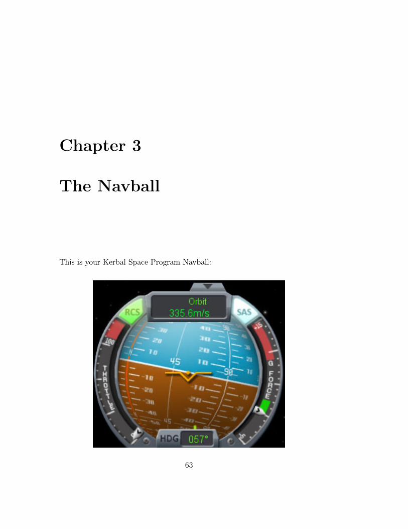
Chapter 3
The Navball
This is your Kerbal Space Program Navball:
63
64 CHAPTER 3. THE NAVBALL
Right off the bat, couple of things:
• If you want to hide the navball, click on the little black arrow (rightabove where it says ”Orbit” in the above picture), or press the .
(period) key ON THE NUMERIC KEYPAD.
• If it’s not showing (like the default in map mode), same thing, eitherclick on the little black arrow at the bottom of the screen, or press the. (period) key on the numeric keypad.
The navball shows you, at different times, certain characteristics of yourvehicle that are important:
• which direction your vehicle is pointing;
• which direction your vehicle is moving;
• which direction your target is located;
• how much you have to fire your engines to accomplish a maneuver;
• which direction you should fire your engines for a maneuver;
• how much throttle you are currently using;
• what ”mode” the navball is in;
• etc.
I’m going to explain each indicator on the navball separately. Where theyare related to another indicator I will mention that.
The first thing we have to understand about the navball, is that it worksin different modes. In the picture above, our navball is showing ”Orbit:”and ”335.6m/s”. This indicates that our orbital velocity is currently, 335.6m/s. We can click on the word ”Orbit:” and it will change to ”Surface:” and,probably, show a different speed. The speed shown when in ”Surface” mode

3.1. NAVBALL INDICATORS 65
is the speed in relation to the surface of the body we are orbiting, launchingfrom or landing on.
Additionally, if you have a target selected, and click on ”Surface” on thenavball, it will switch to ”Target” and show another speed. The speed shownis the relative velocity between your vehicle and the target (how fast you aremoving towards, or away from, your target).
So, we basically have three modes that the navball can operate in: we’llcall these ”Orbit mode”, ”Surface mode” and ”Target mode”, hopefully,consistently, throughout the book.
3.1 Navball Indicators
3.1.1 Prograde
In Orbit mode, the prograde indicator tells you which direction youshould point if you want to be facing the exact direction that yourvehicle is moving. If you want to increase your orbital velocity,point prograde, in Orbit mode, and thrust in that direction.
In Surface mode, the prograde indicator tells you which direction youshould point if you want to be facing the direction that your vehicle is movingrelative to the surface of the body you are orbiting/launching/landing. If youwant to increase your surface velocity, point toward the prograde marker, inSurface mode, and thrust in that direction.
In Target mode, the prograde indicator tells you which direction youshould point if you want to be facing the direction that your vehicle is movingrelative to your target. If you want to increase the relative velocity betweenyour vehicle and your target, point toward the prograde marker, in Targetmode, and thrust in that direction.
3.1.2 Retrograde
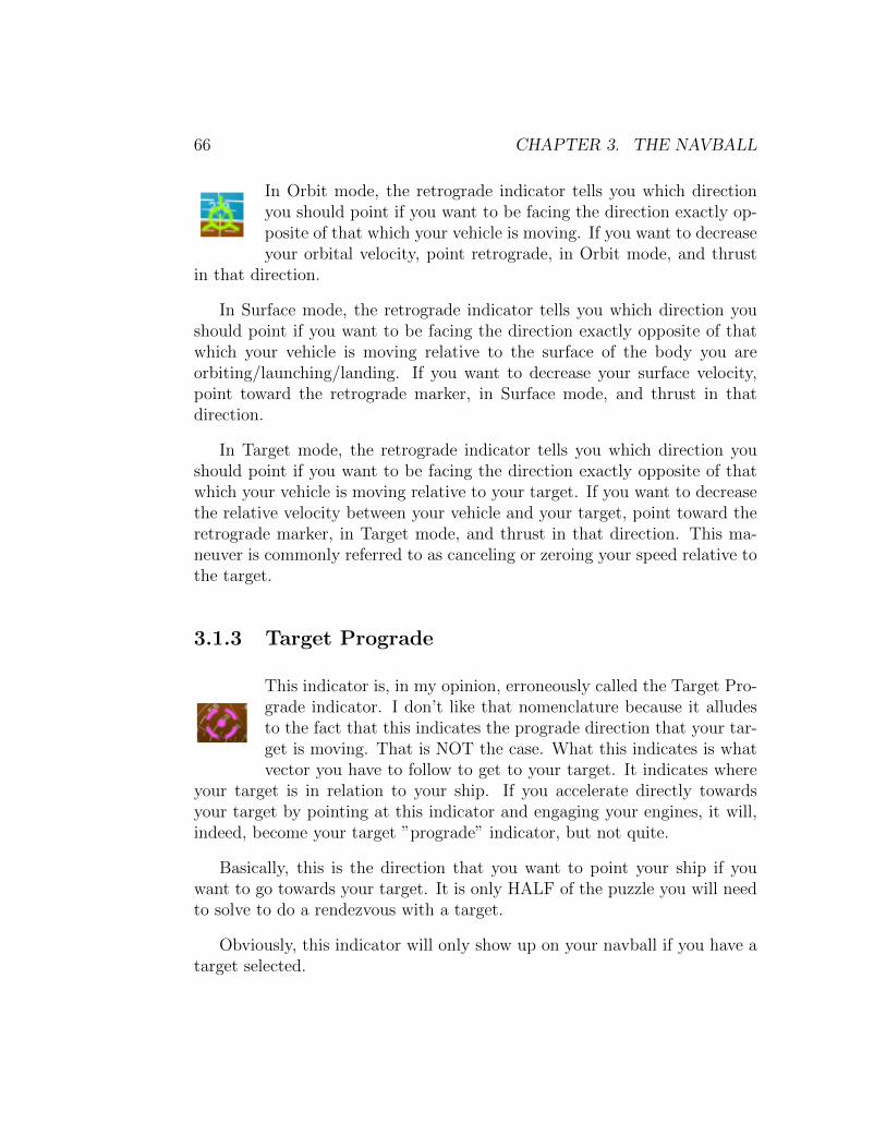
66 CHAPTER 3. THE NAVBALL
In Orbit mode, the retrograde indicator tells you which directionyou should point if you want to be facing the direction exactly op-posite of that which your vehicle is moving. If you want to decreaseyour orbital velocity, point retrograde, in Orbit mode, and thrust
in that direction.
In Surface mode, the retrograde indicator tells you which direction youshould point if you want to be facing the direction exactly opposite of thatwhich your vehicle is moving relative to the surface of the body you areorbiting/launching/landing. If you want to decrease your surface velocity,point toward the retrograde marker, in Surface mode, and thrust in thatdirection.
In Target mode, the retrograde indicator tells you which direction youshould point if you want to be facing the direction exactly opposite of thatwhich your vehicle is moving relative to your target. If you want to decreasethe relative velocity between your vehicle and your target, point toward theretrograde marker, in Target mode, and thrust in that direction. This ma-neuver is commonly referred to as canceling or zeroing your speed relative tothe target.
3.1.3 Target Prograde
This indicator is, in my opinion, erroneously called the Target Pro-grade indicator. I don’t like that nomenclature because it alludesto the fact that this indicates the prograde direction that your tar-get is moving. That is NOT the case. What this indicates is whatvector you have to follow to get to your target. It indicates where
your target is in relation to your ship. If you accelerate directly towardsyour target by pointing at this indicator and engaging your engines, it will,indeed, become your target ”prograde” indicator, but not quite.
Basically, this is the direction that you want to point your ship if youwant to go towards your target. It is only HALF of the puzzle you will needto solve to do a rendezvous with a target.
Obviously, this indicator will only show up on your navball if you have atarget selected.
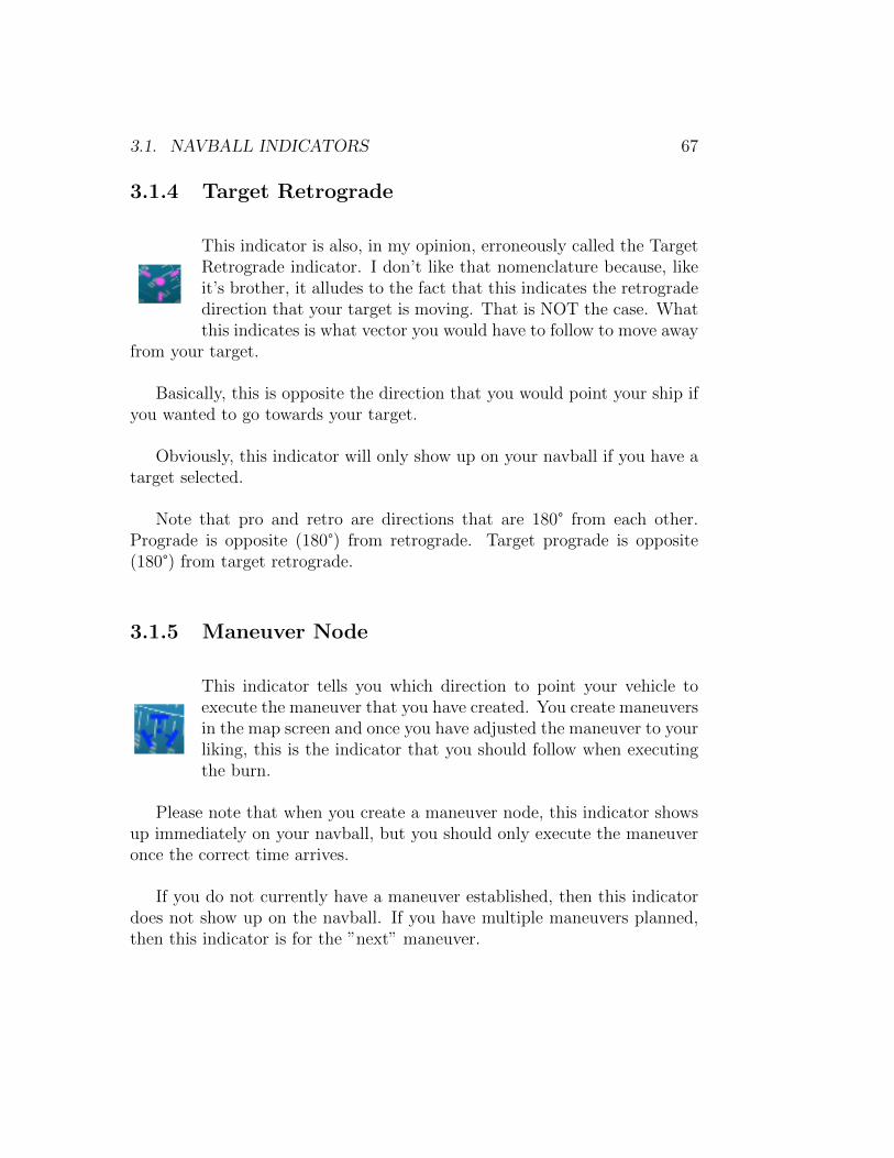
3.1. NAVBALL INDICATORS 67
3.1.4 Target Retrograde
This indicator is also, in my opinion, erroneously called the TargetRetrograde indicator. I don’t like that nomenclature because, likeit’s brother, it alludes to the fact that this indicates the retrogradedirection that your target is moving. That is NOT the case. Whatthis indicates is what vector you would have to follow to move away
from your target.
Basically, this is opposite the direction that you would point your ship ifyou wanted to go towards your target.
Obviously, this indicator will only show up on your navball if you have atarget selected.
Note that pro and retro are directions that are 180° from each other.Prograde is opposite (180°) from retrograde. Target prograde is opposite(180°) from target retrograde.
3.1.5 Maneuver Node
This indicator tells you which direction to point your vehicle toexecute the maneuver that you have created. You create maneuversin the map screen and once you have adjusted the maneuver to yourliking, this is the indicator that you should follow when executingthe burn.
Please note that when you create a maneuver node, this indicator showsup immediately on your navball, but you should only execute the maneuveronce the correct time arrives.
If you do not currently have a maneuver established, then this indicatordoes not show up on the navball. If you have multiple maneuvers planned,then this indicator is for the ”next” maneuver.
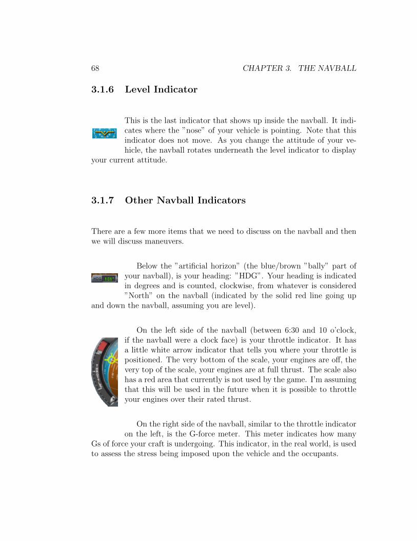
68 CHAPTER 3. THE NAVBALL
3.1.6 Level Indicator
This is the last indicator that shows up inside the navball. It indi-cates where the ”nose” of your vehicle is pointing. Note that thisindicator does not move. As you change the attitude of your ve-hicle, the navball rotates underneath the level indicator to display
your current attitude.
3.1.7 Other Navball Indicators
There are a few more items that we need to discuss on the navball and thenwe will discuss maneuvers.
Below the ”artificial horizon” (the blue/brown ”bally” part ofyour navball), is your heading: ”HDG”. Your heading is indicatedin degrees and is counted, clockwise, from whatever is considered”North” on the navball (indicated by the solid red line going up
and down the navball, assuming you are level).
On the left side of the navball (between 6:30 and 10 o’clock,if the navball were a clock face) is your throttle indicator. It hasa little white arrow indicator that tells you where your throttle ispositioned. The very bottom of the scale, your engines are off, thevery top of the scale, your engines are at full thrust. The scale alsohas a red area that currently is not used by the game. I’m assumingthat this will be used in the future when it is possible to throttleyour engines over their rated thrust.
On the right side of the navball, similar to the throttle indicatoron the left, is the G-force meter. This meter indicates how many
Gs of force your craft is undergoing. This indicator, in the real world, is usedto assess the stress being imposed upon the vehicle and the occupants.
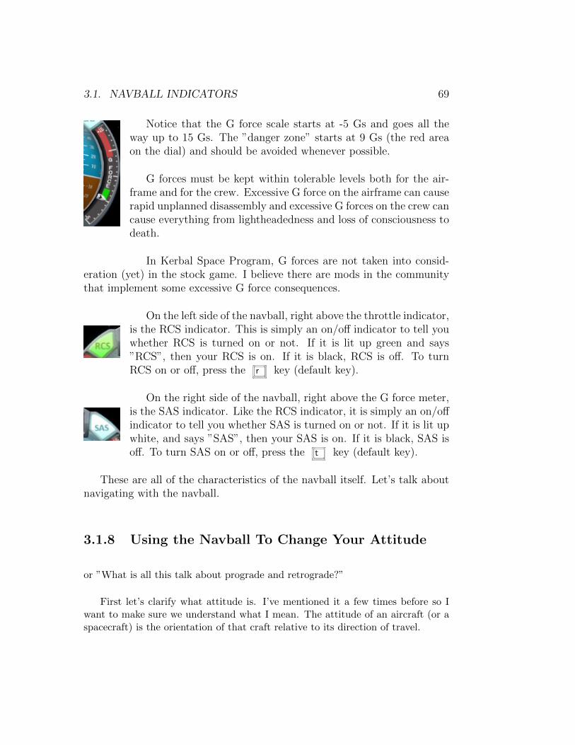
3.1. NAVBALL INDICATORS 69
Notice that the G force scale starts at -5 Gs and goes all theway up to 15 Gs. The ”danger zone” starts at 9 Gs (the red areaon the dial) and should be avoided whenever possible.
G forces must be kept within tolerable levels both for the air-frame and for the crew. Excessive G force on the airframe can causerapid unplanned disassembly and excessive G forces on the crew cancause everything from lightheadedness and loss of consciousness todeath.
In Kerbal Space Program, G forces are not taken into consid-eration (yet) in the stock game. I believe there are mods in the communitythat implement some excessive G force consequences.
On the left side of the navball, right above the throttle indicator,is the RCS indicator. This is simply an on/off indicator to tell youwhether RCS is turned on or not. If it is lit up green and says”RCS”, then your RCS is on. If it is black, RCS is off. To turnRCS on or off, press the r key (default key).
On the right side of the navball, right above the G force meter,is the SAS indicator. Like the RCS indicator, it is simply an on/offindicator to tell you whether SAS is turned on or not. If it is lit upwhite, and says ”SAS”, then your SAS is on. If it is black, SAS isoff. To turn SAS on or off, press the t key (default key).
These are all of the characteristics of the navball itself. Let’s talk aboutnavigating with the navball.
3.1.8 Using the Navball To Change Your Attitude
or ”What is all this talk about prograde and retrograde?”
First let’s clarify what attitude is. I’ve mentioned it a few times before so Iwant to make sure we understand what I mean. The attitude of an aircraft (or aspacecraft) is the orientation of that craft relative to its direction of travel.
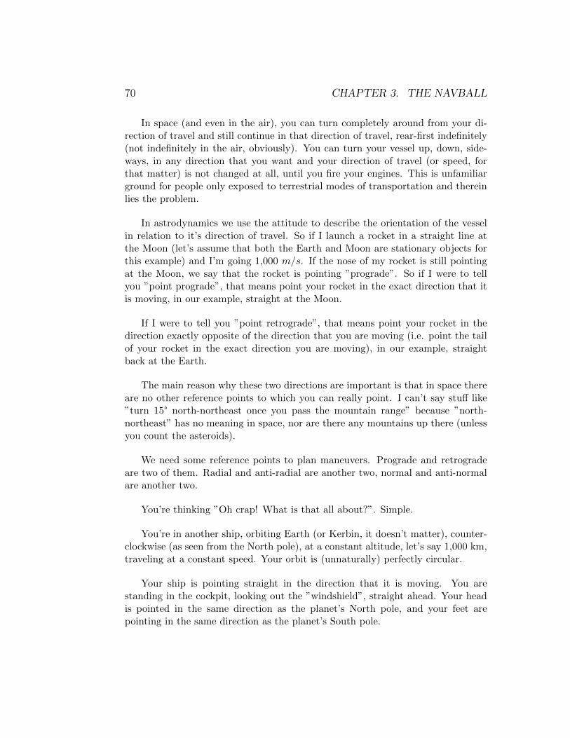
70 CHAPTER 3. THE NAVBALL
In space (and even in the air), you can turn completely around from your di-rection of travel and still continue in that direction of travel, rear-first indefinitely(not indefinitely in the air, obviously). You can turn your vessel up, down, side-ways, in any direction that you want and your direction of travel (or speed, forthat matter) is not changed at all, until you fire your engines. This is unfamiliarground for people only exposed to terrestrial modes of transportation and thereinlies the problem.
In astrodynamics we use the attitude to describe the orientation of the vesselin relation to it’s direction of travel. So if I launch a rocket in a straight line atthe Moon (let’s assume that both the Earth and Moon are stationary objects forthis example) and I’m going 1,000 m/s. If the nose of my rocket is still pointingat the Moon, we say that the rocket is pointing ”prograde”. So if I were to tellyou ”point prograde”, that means point your rocket in the exact direction that itis moving, in our example, straight at the Moon.
If I were to tell you ”point retrograde”, that means point your rocket in thedirection exactly opposite of the direction that you are moving (i.e. point the tailof your rocket in the exact direction you are moving), in our example, straightback at the Earth.
The main reason why these two directions are important is that in space thereare no other reference points to which you can really point. I can’t say stuff like”turn 15° north-northeast once you pass the mountain range” because ”north-northeast” has no meaning in space, nor are there any mountains up there (unlessyou count the asteroids).
We need some reference points to plan maneuvers. Prograde and retrogradeare two of them. Radial and anti-radial are another two, normal and anti-normalare another two.
You’re thinking ”Oh crap! What is that all about?”. Simple.
You’re in another ship, orbiting Earth (or Kerbin, it doesn’t matter), counter-clockwise (as seen from the North pole), at a constant altitude, let’s say 1,000 km,traveling at a constant speed. Your orbit is (unnaturally) perfectly circular.
Your ship is pointing straight in the direction that it is moving. You arestanding in the cockpit, looking out the ”windshield”, straight ahead. Your headis pointed in the same direction as the planet’s North pole, and your feet arepointing in the same direction as the planet’s South pole.

3.1. NAVBALL INDICATORS 71
Where you are looking is prograde.
Right behind your head (180° from prograde) is retrograde.
Straight up, from the top of your head in the direction of the ceiling, is normal.
From the bottom of your feet, straight down (180° from normal), is anti-normal.
Now raise both of your arms straight out from your body (like a ”+”).
Where your left hand is pointing, straight at the center of the planet you areorbiting, is radial (or radial in).
Where your right hand is pointing, away from the center of the planet you areorbiting (180° from radial), is anti-radial or (radial out).
If I now need to give you directions like ”point 30° anti-radial from progradeand 15° normal from prograde”, you know that, assuming you where pointingstraight at prograde to start, that you have to rotate your ship 30° to the rightand 15° up. My entire direction system is now based on prograde, since knowingthat, I can derive all the other 5 ”cardinal” points.
Even if your ship is rotated 180° on it’s long axis and you are, from an externalobservers point of view (your head is now pointing in the direction of the planet’sSouth pole), standing on the ceiling, you know that normal is ”above your head”only if your left arm is pointing ”radial in”. If you’re upside down like I said, yourleft arm will be pointing away from the planet (radial out) and your head will bepointing anti-normal, so you know that the directions I just gave you should nowbe: 30° to the left and 15° down from your frame of reference.
So let’s take a look at the first picture in this article again:
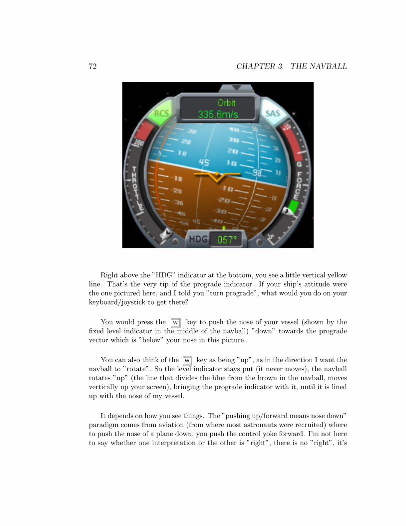
72 CHAPTER 3. THE NAVBALL
Right above the ”HDG” indicator at the bottom, you see a little vertical yellowline. That’s the very tip of the prograde indicator. If your ship’s attitude werethe one pictured here, and I told you ”turn prograde”, what would you do on yourkeyboard/joystick to get there?
You would press the w key to push the nose of your vessel (shown by thefixed level indicator in the middle of the navball) ”down” towards the progradevector which is ”below” your nose in this picture.
You can also think of the w key as being ”up”, as in the direction I want thenavball to ”rotate”. So the level indicator stays put (it never moves), the navballrotates ”up” (the line that divides the blue from the brown in the navball, movesvertically up your screen), bringing the prograde indicator with it, until it is linedup with the nose of my vessel.
It depends on how you see things. The ”pushing up/forward means nose down”paradigm comes from aviation (from where most astronauts were recruited) whereto push the nose of a plane down, you push the control yoke forward. I’m not hereto say whether one interpretation or the other is ”right”, there is no ”right”, it’s
3.1. NAVBALL INDICATORS 73
anti-radial, remember? It’s all a matter of interpretation and whatever works foryou is the best.
I only explain this here because throughout this book I will say (and havealready said, above) ”up” and ”down”. When I say ”up” I mean press the s
key to move your nose up; when I say ”down” I mean press the w key to moveyour nose down. I want to avoid the confusion of ”you said down, so I presseds ” even though s is below w on the keyboard, s is up, w is down.That’s what works for me, so that’s how I use them. If you understand them theopposite, that’s great, it works for you, but then you have to translate what I sayinto your terminology.
Now that we understand the basic ”directions” involved in maneuvering inspace our next section will cover maneuver nodes.
3.1.9 Maneuver Nodes
To create a maneuver node, you have to switch to map view ( m key). If you nowclick anywhere on your orbit (the blue line in map mode), a popup will appearwith a button ”Add Maneuver”. If you click on that button, a maneuver nodeis created. When created, the maneuver node doesn’t do anything, it’s just aplaceholder. When you start playing with the little handles (6 of them, attachedto the maneuver node along the 6 different ”cardinal” directions we just discussed)the maneuver node starts to have meaning.
One of the ”golden rules” of orbital maneuvers is this: any change you maketo your orbit, affects the opposite side of your orbit. Example: If I ”speed up”,by thrusting prograde, at my apoapsis, I raise my periapsis. If I thrust progradeat my periapsis, I raise my apoapsis. Similarly, if I ”slow down”, by thrustingretrograde, at my apoapsis, I lower my periapsis. If I thrust retrograde at myperiapsis, I lower my apoapsis.
So a very common orbital maneuver, that we will discuss in more detail later, iscircularization. Typically, when you launch a craft, you’re launching it ”upwards”from the planet. I’m not going to say straight up, because that’s a bad idea, butit is in a generally upwards direction.
If you look in map mode, as your launching, you will see a parabola forming.The very top of your parabola, your highest point, is your apoapsis, and should

74 CHAPTER 3. THE NAVBALL
have a little blue ”Ap” indicator on it. What that parabola is showing you isthat, if you leave your ship on it’s current trajectory, it will, eventually fall back toKerbin. We have an apoapsis in our trajectory, but no periapsis. Actually thereIS a periapsis, it’s ZERO, so the game doesn’t show it. But it’s there.
If I want to get into orbit, I need to make both my apoapsis and my periapsishigher than 70,000 meters (for a Low Kerbin Orbit). Let’s assume my apoapsisis at 80,000 meters already, my engines are turned off and my current altitude is50,000 meters. I’m essentially ”coasting” towards my apoapsis. What do I do toget into orbit? What am I trying to accomplish?
Low Kerbin Orbit is a trajectory where both apoapsis and periapsis is above70,000 meters.
Ok. . . checklist time:
• Apoapsis above 70,000 meters: check
• Periapsis above 70,000 meters: not so much
But wait a minute, didn’t we just talk about ”raising periapsis”? Oh yeah. . . ”IfI ’speed up’, by thrusting prograde, at my apoapsis, I raise my periapsis.” Let’sdo that. . .
I line my ship up, pointing prograde. Wait for the apoapsis, and fire my engines.Nothing seems to happen initially, but my orbit’s getting ”wider”. No, wait! Aperiapsis just showed up on the other side of the planet. 5,000 meters. . . 10,000meters. . . 50,000 meters. . . 80,000 meters! Quick, shut down the engine ( x key).My orbit is now ”circularized” (hopefully it’s roughly circular). That’s called”winging it”.
Let’s try that in a less stressful, more planned, way.
We’re back at 50,000 meters. Apoapsis is at 80,000 meters. Engines are off.We’re coasting towards our apoapsis.

3.1. NAVBALL INDICATORS 75
In map mode. Create a maneuver node AT your apoapsis:
Click on the little blue ”Ap” indicator (notice the little blue dot on the orbitnear the apopasis indicator)
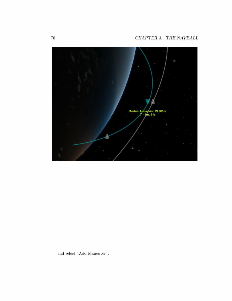
76 CHAPTER 3. THE NAVBALL
and select ”Add Maneuver”.
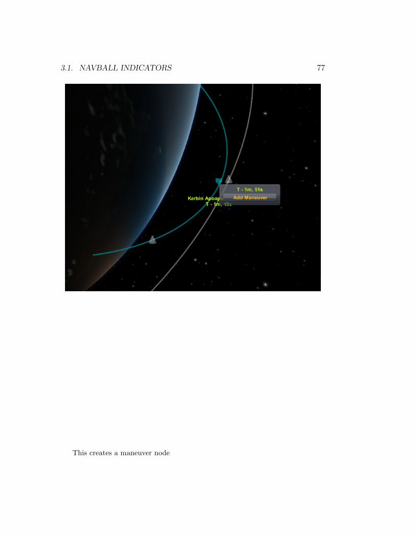
3.1. NAVBALL INDICATORS 77
This creates a maneuver node

78 CHAPTER 3. THE NAVBALL
Now what we did before was to thrust prograde, so we’re going to plan thismaneuver in the same fashion.
So grab the little prograde marker on the maneuver node (it looks the sameas the prograde marker on the navball) and pull it slowly away from the center ofthe maneuver node. An orange-ish line appears on the map. That’s the new orbityou will have, if you execute the maneuver node. There’s also an orange-ish ”Ap”and ”Pe” indicator that tells you what your apoapsis and periapsis will be in thisnew orbit.
If your periapsis isn’t high enough (or hasn’t shown up at all yet), keep ”stretch-ing” that prograde marker handle. The process here is: adjust maneuver by drag-ging prograde handle; release mouse; mouse over (orange) periapsis to see height;and keep doing that until the periapsis is high enough. Made it too high? Ad-just maneuver by dragging retrograde handle; release mouse; mouse over (orange)

3.1. NAVBALL INDICATORS 79
periapsis to see height; and keep doing that until the periapsis is where you wantit.
Once you’ve adjusted your maneuver properly, you should have a roughly circu-lar orange-ish orbit around Kerbin with both an apoapsis and periapsis of, roughly,80,000 meters.
Let’s check out our apoapsis and periapsis for the new orbit:

80 CHAPTER 3. THE NAVBALL
Not perfect, but close enough. Both apoapsis and periapsis are out of theatmosphere.
So let’s switch back out of map mode. Press m again.
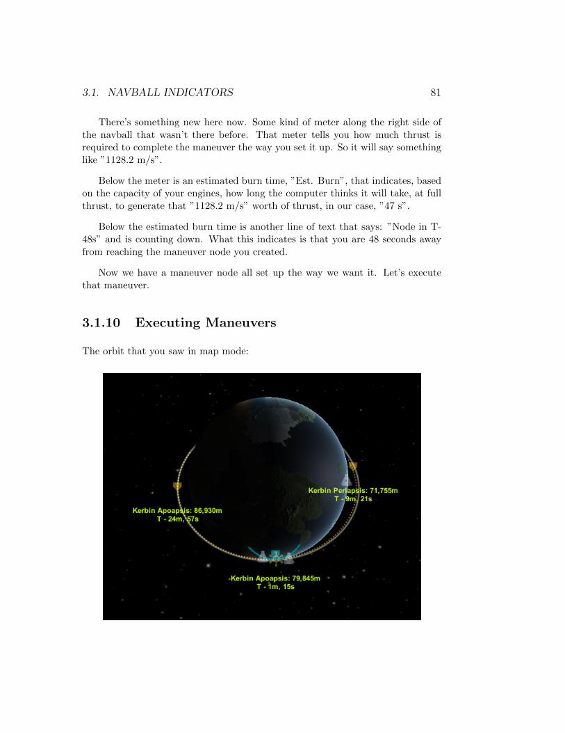
3.1. NAVBALL INDICATORS 81
There’s something new here now. Some kind of meter along the right side ofthe navball that wasn’t there before. That meter tells you how much thrust isrequired to complete the maneuver the way you set it up. So it will say somethinglike ”1128.2 m/s”.
Below the meter is an estimated burn time, ”Est. Burn”, that indicates, basedon the capacity of your engines, how long the computer thinks it will take, at fullthrust, to generate that ”1128.2 m/s” worth of thrust, in our case, ”47 s”.
Below the estimated burn time is another line of text that says: ”Node in T-48s” and is counting down. What this indicates is that you are 48 seconds awayfrom reaching the maneuver node you created.
Now we have a maneuver node all set up the way we want it. Let’s executethat maneuver.
3.1.10 Executing Maneuvers
The orbit that you saw in map mode:

82 CHAPTER 3. THE NAVBALL
is calculated as if the maneuver were executed in an instant. This means thatfor your orbit to end up exactly as projected, you would have to change yourvelocity by 1,128.s m/s instantly, the moment you hit the node. Since that isphysically impossible, because your engines don’t work that way, it is an estimate.
Since it is an estimate, we’re going to do our best to estimate how to executethe maneuver as well.
Remember that any change you make in your orbit, affects the opposite side ofyour orbit (i.e. burning prograde at apoapsis, raises your periapsis and vice-versa).Therefore we are executing our burn at our apoapsis (to raise our periapsis fromzero, in this case). But if my burn is going to take 47 seconds and I start it exactlyat the node, per the countdown clock, I will be executing the burn, effectively,AFTER having passed my apoapsis.
A good rule of thumb, to execute a burn, is to ”split” the burn evenly aroundyour node. So if the burn is 47 seconds, cut that in half, 23.5 seconds, and startexecuting the burn 23.5 seconds BEFORE hitting the node; and continue burningan additional 23.5 seconds, after the node. That way the ”error” in your maneuveris distributed evenly at both sides of the node.
This technique does not work very efficiently if your burn time is very long(i.e. more than a minute). This is because the longer the burn, the more ”off” theprediction of the resulting orbit is going to be (because the prediction assumes 0seconds of burn time for the maneuver).
An even better approach is to execute the maneuver in steps. In this particularcase, we cannot execute the maneuver in steps. Because this is a circularizationmaneuver, you don’t have the luxury of executing a smaller maneuver now, andexecuting another small maneuver on your next orbit. There will be no next orbitunless you circularize your orbit.
An example of a maneuver that can be executed in steps is one where you wishto change your inclination by 90°. Let’s assume that you are in a circular orbit, at80,000 meters.

3.1. NAVBALL INDICATORS 83
The ∆v for a 90° inclination change is enormous. 3,188 m/s. The estimatedburn time is 1 minute and 56 seconds. A burn that long will result in your orbit notbeing even remotely close to the target you set, because the burn will be executedalmost 1 minute before the node and last until about 1 minute after the node.
In a case like this, you would be better off executing a smaller inclinationchange, for example, 20°; on your next orbit, execute another 20° inclinationchange; and so on until you have achieved the desired orbit. Please note thatdoing it this way does not make the maneuver ”cheaper” in any way. You will stillexpend the same 3,188 m/s of ∆v to make the full 90° inclination change, but youwill have more control over the resulting final orbit by doing it in steps. In fact,the multiple maneuvers might cost you a little more in terms of ∆v, because ofthe inevitable errors in piloting.
But enough about the economics of maneuvers. . .
To execute any maneuver, your want to adjust the attitude of your vehicle, topoint to the maneuver node indicator on the navball.
84 CHAPTER 3. THE NAVBALL
Once you are pointing directly at the maneuver node indicator, you shouldwait until the appropriate time to start your maneuver. The discussion above, onwhen to execute a maneuver, is simply a suggestion that I follow when executingmaneuvers. You are free to execute the maneuvers in the fashion that you seebest.
As you fire your engines, you will notice the ∆v meter on the right side of thenavball start to decrease. Once it reaches ”0”, you should stop your engines. Alsonote that during the maneuver, you should try to keep your vessel pointed in theright direction, towards the maneuver node indicator.
If you go ”off” course slightly, you do not have to worry, because both themaneuver node indicator and the ∆v meter are recalculated, in real time, as youexecute the maneuver. The system does it’s best to make sure that, when youare done executing the maneuver, you end up with an orbit as close as possible towhat was projected when you created the maneuver node.
A tip for executing maneuvers: As you approach the end of your burn (whenthe ∆v meter is almost ”empty”), you might want to throttle down your enginesslowly. That way you have more control over the cut off, as close to zero as possible,for your maneuver. If you have a very powerful engine, or set of engines, it will eatthrough the required ∆v pretty fast, and that will make it harder for your to cutthe engines at the appropriate time, most likely ”overshooting” your maneuver.
Just remember that the burn time was calculated at full thrust, so if youthrottle back the end of the burn, it is going to take longer, so take that intoconsideration when ”splitting” your burn around the node. Give yourself an extrafew seconds of total burn time for a controlled shut down of your engines.
Now that we’re ”experts” in maneuvers, let’s start discussing the differenttypes of maneuvers that are typically executed in game.
Chapter 4
Orbital Maneuvers
4.1 Gravity Turn
A gravity turn is a maneuver that is used to optimize the trajectory of the vehicleduring launch (or landing). It’s main purpose is the utilization of the body’sgravity to assist in steering the vehicle to its desired trajectory.
It has two advantages over using solely thrust in controlling the vehicle:
1. We don’t use the thrust to steer the vehicle, therefore more thrust is availableto accelerate.
2. During ascent, the vehicle can maintain a low angle of attack (or zero). Thisminimizes the stress put on the vehicle from aerodynamic forces, allowingfor a less robust, therefore lighter vehicle.
Why use a gravity turn?
During launch, the vehicle goes straight up, gaining vertical speed and altitude.Gravity, at this point, is acting directly against the thrust of the vehicle, loweringits vertical acceleration. The losses that occur during this phase of the flight areknown as gravity drag.
85
86 CHAPTER 4. ORBITAL MANEUVERS
The sooner the vehicle pitches over its ascent, the sooner the effects of gravitydrag can be minimized. The earlier this pitch over happens, the better. If thevertical velocity of the vehicle is high when the pitch over maneuver is executed,the aerodynamic loads on the vehicle can be very high. This is the general rule,in real life.
In Kerbal Space Program, the general rule of thumb is to initiate the pitchover maneuver anywhere between 7,000 meters and 15,000 meters of altitude.
In real life, the angle (not the heading, how much we pitch the vehicle over; theheading is entirely up to the desired trajectory, though in most cases in the gamewe are aiming for an equatorial orbit, therefore the heading is 90°) into which weturn the vehicle, during the pitch over maneuver, varies with the vehicle.
An important part of an ideal gravity turn is that the gimbaling of the enginesis only used during the initial pitching over maneuver. From that point forward thevehicle’s engines should always be pointing straight down the axis of the rocket.
Gravity will slowly turn the rocket further and further towards the horizon asthe rocket accelerates. By no longer actively turning the rocket in one direction oranother, we minimize the aerodynamic stress that the rocket incurs as a result ofsuch maneuvers. The intent of a gravity turn is to, by the time the rocket levelsoff (is flying parallel to the ground), have gained sufficient altitude and velocity tobe in a stable orbit.
With vehicles that are launching from a planet with a dense atmosphere, thesmaller the angle of the initial pitch over, the better, since our main goal in thisscenario is to get out of the thicker part of the atmosphere more quickly. Thefaster we get out of the thicker part of the atmosphere, the more we reduce theaerodynamic drag and aerodynamic stress that the vehicle will suffer during launch.
Maximum dynamic pressure is another concern during launch. In Kerbal SpaceProgram, as of this writing, it is not yet a concern. Once aerodynamic calculationsare included in the KSP universe, it might need to be addressed.
Maximum dynamic pressure, sometimes referred to as ”max Q”, is due to thebuild up of dynamic pressure due to the acceleration against the thicker part of theatmosphere. Again, similar to the turn early or turn late for the gravity turn, it isa tradeoff between gaining more speed while in the lower part of the atmosphereand making the vehicle heavier, since it needs to withstand greater pressure, or alighter vehicle and gaining less speed while in the lower atmosphere.

4.2. CIRCULARIZING YOUR ORBIT 87
The space shuttle, for example, throttles back its main engines during theinitial phase of the ascent as it approaches max Q to reduce stress on the airframe.Once it passes through the thicker part of the atmosphere, it accelerates again tomaximum thrust to gain speed as fast as possible.
4.2 Circularizing your Orbit
4.2.1 Achieving Orbit
Achieving orbit, for the first time, is one of the most gratifying experiences thatyou will encounter in game. A lot of beginners in the game tend to launch theirrockets straight up. Launching a vehicle straight up will not put your rocket inorbit. A lot of times, even going up at all can be a challenge.
For our purposes, we will consider an orbit as a trajectory that your vesselfollows in such a way that it will never ”fall” back down to the body it is orbiting.If we take Kerbin as an example, for the vessel to not fall back to the planet, weneed to satisfy a single condition:
• The trajectory has to be high enough, at all points, that the vessel is nolonger being affected by the atmosphere (which causes drag and makes thevessel lose speed)
The parameters of such an orbit are fairly simple: At no point, in our orbit,should our vessel go below ∼70,000 meters.
Orbiting is not so much about vertical velocity, as it is about horizontal velocity.For an object to ”orbit” another object, it needs to have a horizontal velocity, inrelation to the object it wishes to orbit, high enough that it will constantly ”miss”the object as it continuously ”falls” towards it.
What that velocity needs to be varies according to the altitude of the orbit:the closer the orbiting object is to the body it is orbiting, the higher the requiredvelocity to maintain that orbit. The previous statement assumes that the physicalcharacteristics of the two bodies are the same in all cases. Also note that the
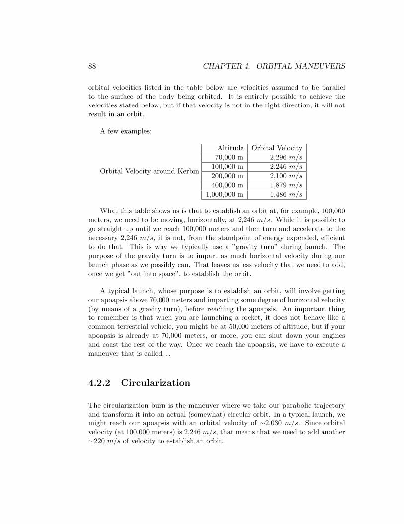
88 CHAPTER 4. ORBITAL MANEUVERS
orbital velocities listed in the table below are velocities assumed to be parallelto the surface of the body being orbited. It is entirely possible to achieve thevelocities stated below, but if that velocity is not in the right direction, it will notresult in an orbit.
A few examples:
Orbital Velocity around Kerbin
Altitude Orbital Velocity
70,000 m 2,296 m/s
100,000 m 2,246 m/s
200,000 m 2,100 m/s
400,000 m 1,879 m/s
1,000,000 m 1,486 m/s
What this table shows us is that to establish an orbit at, for example, 100,000meters, we need to be moving, horizontally, at 2,246 m/s. While it is possible togo straight up until we reach 100,000 meters and then turn and accelerate to thenecessary 2,246 m/s, it is not, from the standpoint of energy expended, efficientto do that. This is why we typically use a ”gravity turn” during launch. Thepurpose of the gravity turn is to impart as much horizontal velocity during ourlaunch phase as we possibly can. That leaves us less velocity that we need to add,once we get ”out into space”, to establish the orbit.
A typical launch, whose purpose is to establish an orbit, will involve gettingour apoapsis above 70,000 meters and imparting some degree of horizontal velocity(by means of a gravity turn), before reaching the apoapsis. An important thingto remember is that when you are launching a rocket, it does not behave like acommon terrestrial vehicle, you might be at 50,000 meters of altitude, but if yourapoapsis is already at 70,000 meters, or more, you can shut down your enginesand coast the rest of the way. Once we reach the apoapsis, we have to execute amaneuver that is called. . .
4.2.2 Circularization
The circularization burn is the maneuver where we take our parabolic trajectoryand transform it into an actual (somewhat) circular orbit. In a typical launch, wemight reach our apoapsis with an orbital velocity of ∼2,030 m/s. Since orbitalvelocity (at 100,000 meters) is 2,246 m/s, that means that we need to add another∼220 m/s of velocity to establish an orbit.
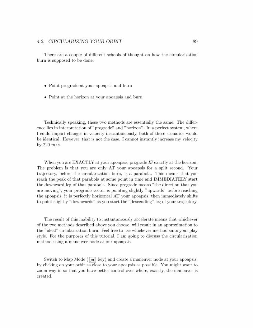
4.2. CIRCULARIZING YOUR ORBIT 89
There are a couple of different schools of thought on how the circularizationburn is supposed to be done:
• Point prograde at your apoapsis and burn
• Point at the horizon at your apoapsis and burn
Technically speaking, these two methods are essentially the same. The differ-ence lies in interpretation of ”prograde” and ”horizon”. In a perfect system, whereI could impart changes in velocity instantaneously, both of these scenarios wouldbe identical. However, that is not the case. I cannot instantly increase my velocityby 220 m/s.
When you are EXACTLY at your apoapsis, prograde IS exactly at the horizon.The problem is that you are only AT your apoapsis for a split second. Yourtrajectory, before the circularization burn, is a parabola. This means that youreach the peak of that parabola at some point in time and IMMEDIATELY startthe downward leg of that parabola. Since prograde means ”the direction that youare moving”, your prograde vector is pointing slightly ”upwards” before reachingthe apoapsis, it is perfectly horizontal AT your apoapsis, then immediately shiftsto point slightly ”downwards” as you start the ”descending” leg of your trajectory.
The result of this inability to instantaneously accelerate means that whicheverof the two methods described above you choose, will result in an approximation tothe ”ideal” circularization burn. Feel free to use whichever method suits your playstyle. For the purposes of this tutorial, I am going to discuss the circularizationmethod using a maneuver node at our apoapsis.
Switch to Map Mode ( m key) and create a maneuver node at your apoapsis,by clicking on your orbit as close to your apoapsis as possible. You might want tozoom way in so that you have better control over where, exactly, the maneuver iscreated.
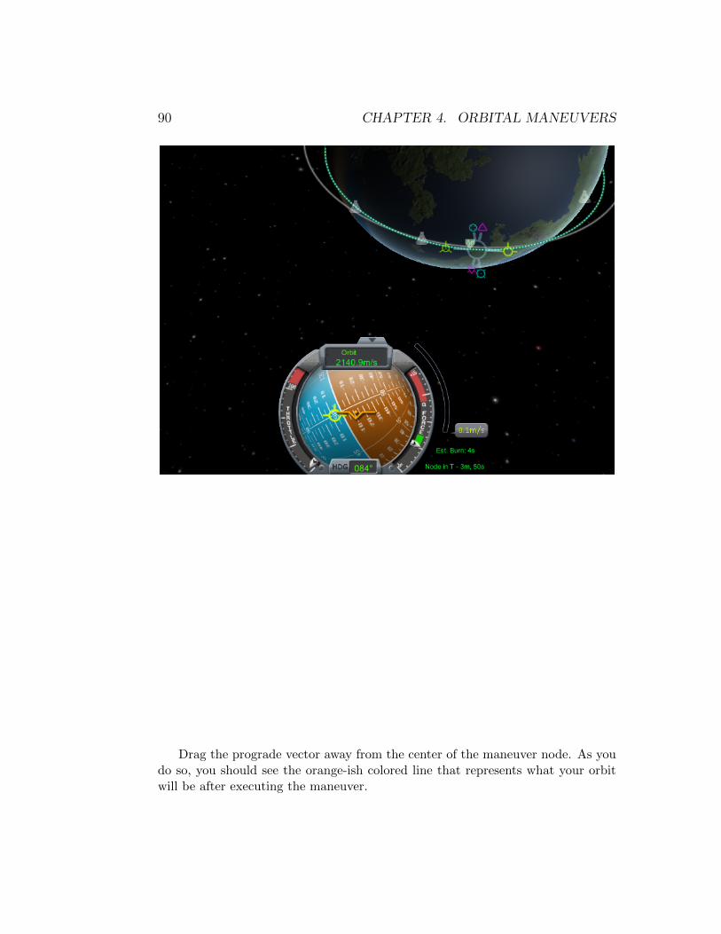
90 CHAPTER 4. ORBITAL MANEUVERS
Drag the prograde vector away from the center of the maneuver node. As youdo so, you should see the orange-ish colored line that represents what your orbitwill be after executing the maneuver.
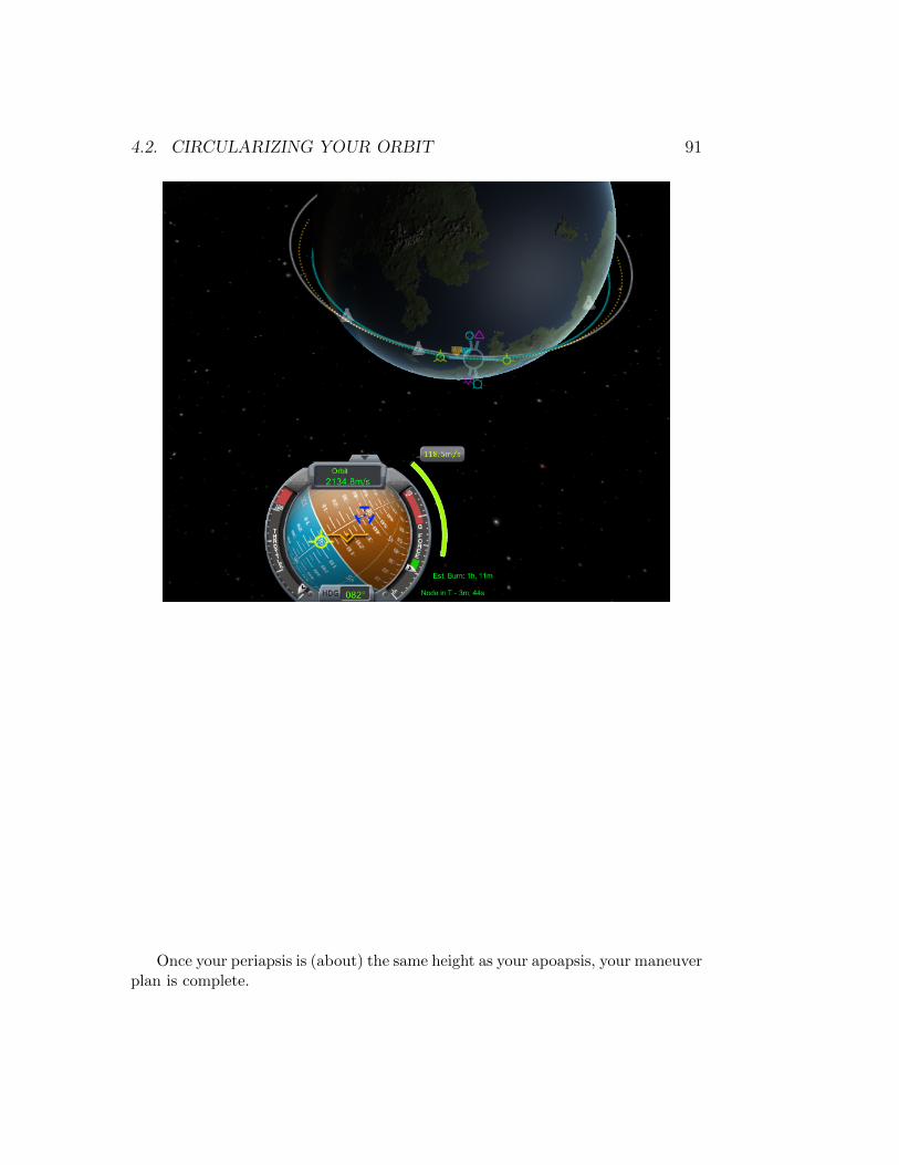
4.2. CIRCULARIZING YOUR ORBIT 91
Once your periapsis is (about) the same height as your apoapsis, your maneuverplan is complete.

92 CHAPTER 4. ORBITAL MANEUVERS
Look at the ”Est. Burn” time and the time to Node, next to the navball.
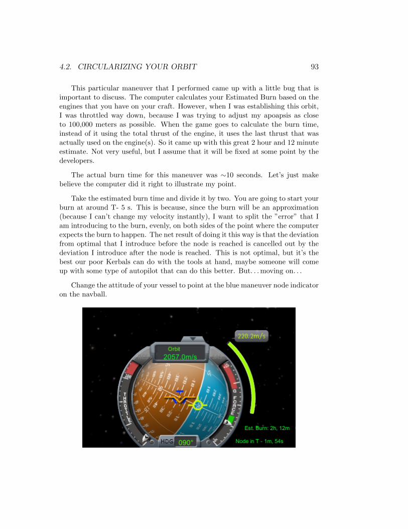
4.2. CIRCULARIZING YOUR ORBIT 93
This particular maneuver that I performed came up with a little bug that isimportant to discuss. The computer calculates your Estimated Burn based on theengines that you have on your craft. However, when I was establishing this orbit,I was throttled way down, because I was trying to adjust my apoapsis as closeto 100,000 meters as possible. When the game goes to calculate the burn time,instead of it using the total thrust of the engine, it uses the last thrust that wasactually used on the engine(s). So it came up with this great 2 hour and 12 minuteestimate. Not very useful, but I assume that it will be fixed at some point by thedevelopers.
The actual burn time for this maneuver was ∼10 seconds. Let’s just makebelieve the computer did it right to illustrate my point.
Take the estimated burn time and divide it by two. You are going to start yourburn at around T- 5 s. This is because, since the burn will be an approximation(because I can’t change my velocity instantly), I want to split the ”error” that Iam introducing to the burn, evenly, on both sides of the point where the computerexpects the burn to happen. The net result of doing it this way is that the deviationfrom optimal that I introduce before the node is reached is cancelled out by thedeviation I introduce after the node is reached. This is not optimal, but it’s thebest our poor Kerbals can do with the tools at hand, maybe someone will comeup with some type of autopilot that can do this better. But. . . moving on. . .
Change the attitude of your vessel to point at the blue maneuver node indicatoron the navball.

94 CHAPTER 4. ORBITAL MANEUVERS
When the time arrives, fire your engines
Notice how when I started the burn, the estimate got more realistic. This isone of the characteristics of both the ∆v meter and the maneuver node indicatoron your navball. For the duration of the burn, they will constantly update for thesame target trajectory. This means that if you deviate from either the path or theburn profile (you’re not burning full throttle, or worse, your stage runs out mid-burn and you have to switch to another stage) both the meter and the indicatorwill update for the new total ∆v that still needs to be expended and the vectoryou should follow. All so that your final trajectory ends up where you projectedwith the maneuver node (or as close as possible).
Watch the ∆v meter next to the navball, it will slowly countdown the required∆v for the burn

4.2. CIRCULARIZING YOUR ORBIT 95
When you are close to the end of the burn, throttle down a bit. This gives youmore control over engine shutdown, so you can cut the engines at the right timeand not ”overshoot” your goal.
Cut engines ( x key) as soon as the ∆v meter reaches 0.0 (or as close as youcan get without overshooting).
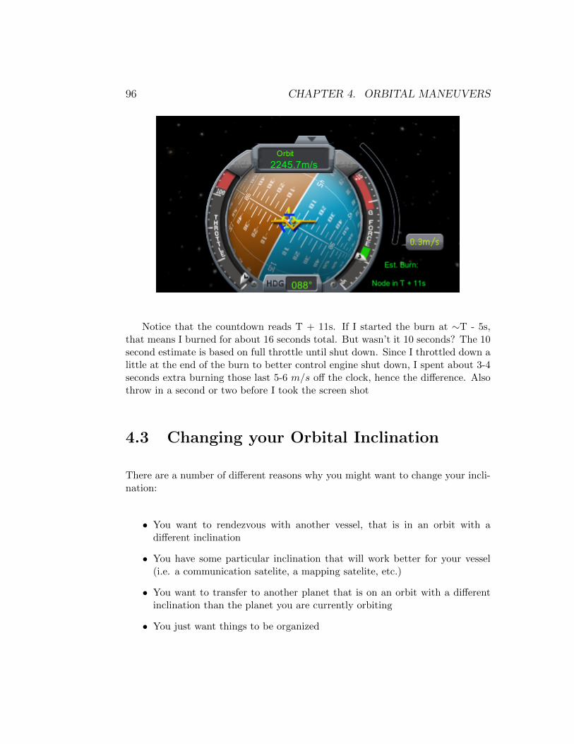
96 CHAPTER 4. ORBITAL MANEUVERS
Notice that the countdown reads T + 11s. If I started the burn at ∼T - 5s,that means I burned for about 16 seconds total. But wasn’t it 10 seconds? The 10second estimate is based on full throttle until shut down. Since I throttled down alittle at the end of the burn to better control engine shut down, I spent about 3-4seconds extra burning those last 5-6 m/s off the clock, hence the difference. Alsothrow in a second or two before I took the screen shot
4.3 Changing your Orbital Inclination
There are a number of different reasons why you might want to change your incli-nation:
• You want to rendezvous with another vessel, that is in an orbit with adifferent inclination
• You have some particular inclination that will work better for your vessel(i.e. a communication satelite, a mapping satelite, etc.)
• You want to transfer to another planet that is on an orbit with a differentinclination than the planet you are currently orbiting
• You just want things to be organized

4.3. CHANGING YOUR ORBITAL INCLINATION 97
Depending on the inclination change that you need, there are a number ofdifferent ways that you can proceed. Some of them are expensive (in terms if ∆v),others are cheap (or cheaper, at least).
As an example, look at the inclination change that we discussed in ”ExecutingManeuvers”. That was an inclination change of 90°You were in an equatorial orbit,and wanted to change to a polar orbit. That is a hugely ”expensive” maneuver,executed as was described. There are other ways to execute inclination changesthat are more ”economical”.
Here is our current orbit:
As you can see, we are in an equatorial orbit at approximately 100,000 meters.What we want to do is change this orbit so it is still at 100,000 meters but isat an inclination of 90° (a polar orbit). The maneuver described below will saveyou ∆v by changing your orbit into a highly elliptical orbit before attempting theinclination change. The main steps of the process are:
• Burn prograde at the periapsis of your current orbit to raise your apoapsisuntil your orbit is highly elliptical. You burn at your periapsis to takeadvantage of the Oberth effect.

98 CHAPTER 4. ORBITAL MANEUVERS
• When at your apoapsis, burn to adjust your inclination as desired. Thisshould require much less ∆v than the maneuver as originally described.Furthermore, we do the inclination change in steps. With our first burn wewill make the orbit ∼30° inclined to the ecliptic plane
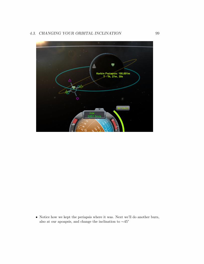
4.3. CHANGING YOUR ORBITAL INCLINATION 99
• Notice how we kept the periapsis where it was. Next we’ll do another burn,also at our apoapsis, and change the inclination to ∼45°
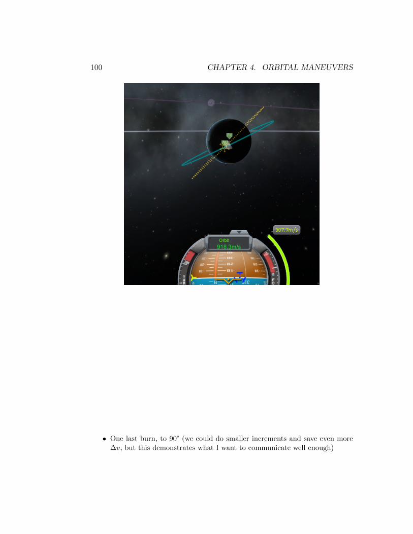
100 CHAPTER 4. ORBITAL MANEUVERS
• One last burn, to 90° (we could do smaller increments and save even more∆v, but this demonstrates what I want to communicate well enough)

4.3. CHANGING YOUR ORBITAL INCLINATION 101
• After your inclination is adjusted, burn retrograde at your periapsis to cir-cularize your orbit once again.
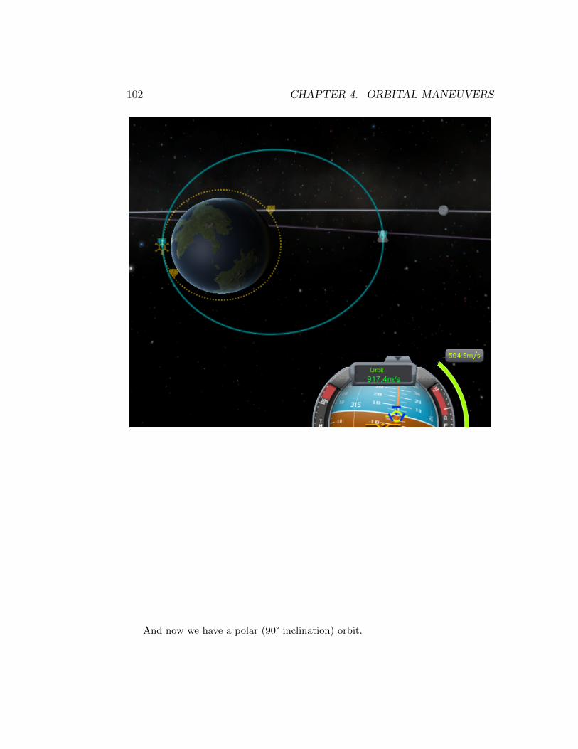
102 CHAPTER 4. ORBITAL MANEUVERS
And now we have a polar (90° inclination) orbit.
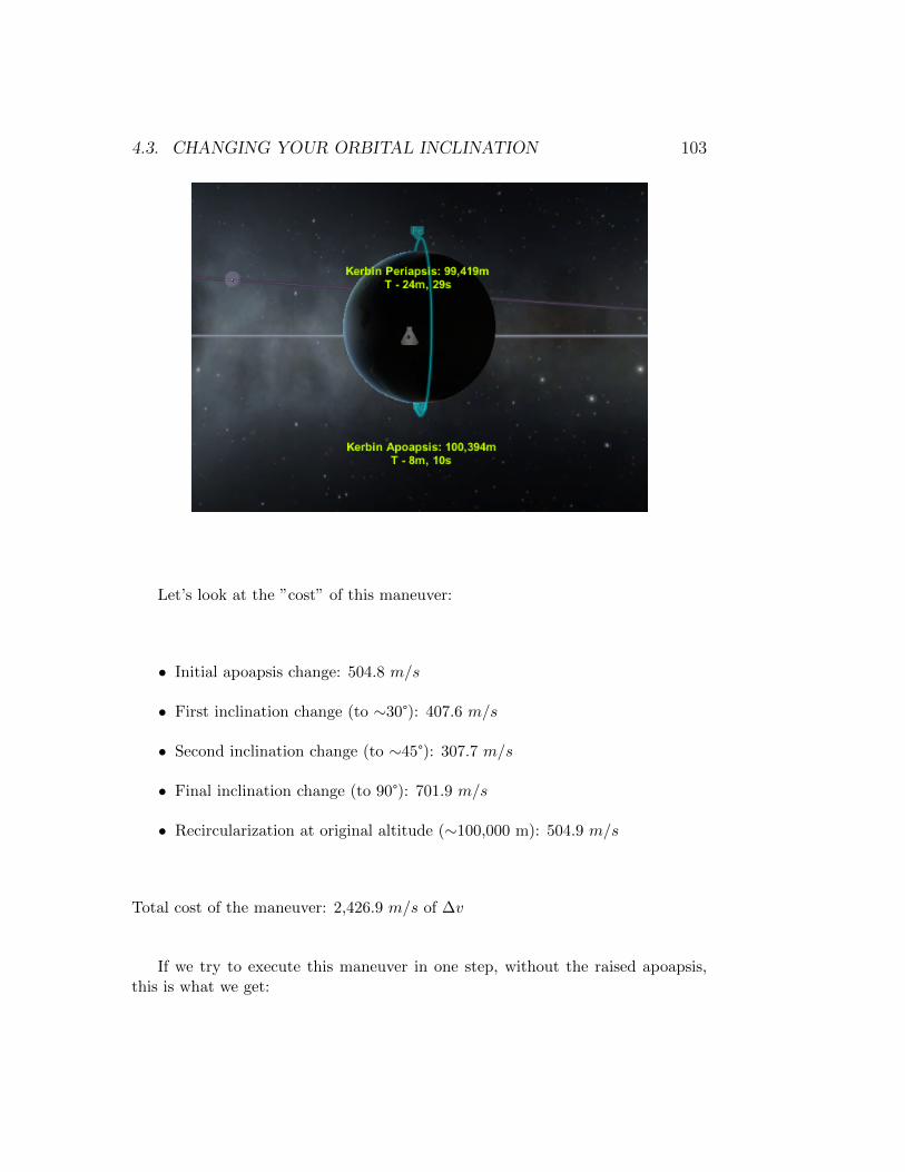
4.3. CHANGING YOUR ORBITAL INCLINATION 103
Let’s look at the ”cost” of this maneuver:
• Initial apoapsis change: 504.8 m/s
• First inclination change (to ∼30°): 407.6 m/s
• Second inclination change (to ∼45°): 307.7 m/s
• Final inclination change (to 90°): 701.9 m/s
• Recircularization at original altitude (∼100,000 m): 504.9 m/s
Total cost of the maneuver: 2,426.9 m/s of ∆v
If we try to execute this maneuver in one step, without the raised apoapsis,this is what we get:

104 CHAPTER 4. ORBITAL MANEUVERS
A maneuver that costs 3,176.5 m/s. Doing it our way, we saved 750 m/s of∆v!
This works because when you do the inclination change, far away from theorbited body, you can make a much smaller adjustment, and that adjustment is”amplified” by the increased distance from the orbited body. But why?
Imagine you are holding a laser pointer and point at a wall from 1 foot away.For you to move the projected dot on the wall 1 foot to the right, you need torotate your hand a certain amount. Now back away from the wall 10 feet. Pointat the same initial spot on the wall. Move the projected dot 1 foot to the right.Notice how much less you had to rotate your hand to achieve the same amount of”movement”.
This is true of pretty much all maneuvers you make in the game. The ear-lier you can make an adjustment to your final target trajectory, the easier (andcheaper) it is to do so. An example: You create a maneuver for a Mun interceptand you have a Mun periapsis of 20,000 meters. While you are still in Kerbin’ssphere of influence, you can make a very small change to your course (typically,
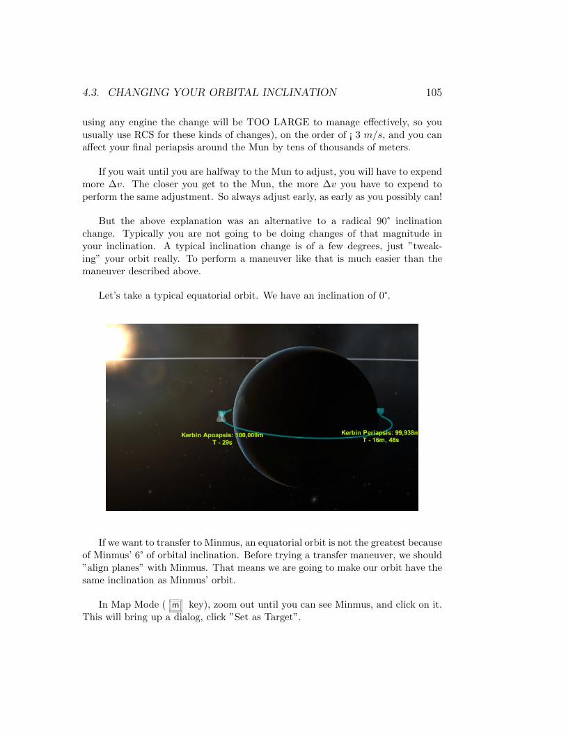
4.3. CHANGING YOUR ORBITAL INCLINATION 105
using any engine the change will be TOO LARGE to manage effectively, so youusually use RCS for these kinds of changes), on the order of ¡ 3 m/s, and you canaffect your final periapsis around the Mun by tens of thousands of meters.
If you wait until you are halfway to the Mun to adjust, you will have to expendmore ∆v. The closer you get to the Mun, the more ∆v you have to expend toperform the same adjustment. So always adjust early, as early as you possibly can!
But the above explanation was an alternative to a radical 90° inclinationchange. Typically you are not going to be doing changes of that magnitude inyour inclination. A typical inclination change is of a few degrees, just ”tweak-ing” your orbit really. To perform a maneuver like that is much easier than themaneuver described above.
Let’s take a typical equatorial orbit. We have an inclination of 0°.
If we want to transfer to Minmus, an equatorial orbit is not the greatest becauseof Minmus’ 6° of orbital inclination. Before trying a transfer maneuver, we should”align planes” with Minmus. That means we are going to make our orbit have thesame inclination as Minmus’ orbit.
In Map Mode ( m key), zoom out until you can see Minmus, and click on it.This will bring up a dialog, click ”Set as Target”.
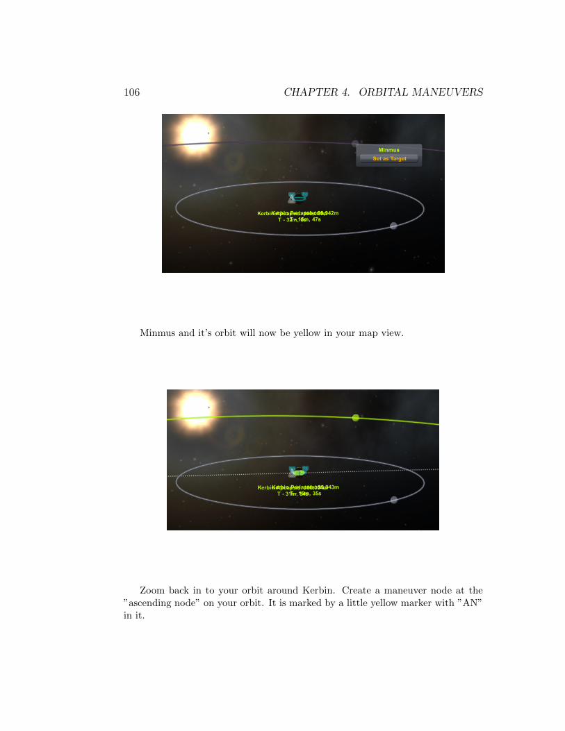
106 CHAPTER 4. ORBITAL MANEUVERS
Minmus and it’s orbit will now be yellow in your map view.
Zoom back in to your orbit around Kerbin. Create a maneuver node at the”ascending node” on your orbit. It is marked by a little yellow marker with ”AN”in it.

4.3. CHANGING YOUR ORBITAL INCLINATION 107
Adjust your camera-view so that you see your orbit and Minmus’ orbit ”edgeon”, so that they both appear as lines to you. Also make sure that you are lookingfrom an angle that the ascending node marker and the descending node markerare right on top of each other

108 CHAPTER 4. ORBITAL MANEUVERS
Drag the anti-normal maneuver ”handle” away from the center of the maneuvernode until your orbit is lined up with Minmus’ orbit
Execute the node: Point your vessel at the blue maneuver node indicator onthe navball; Calculate your burn start time (T - half the burn time); and burnuntil your ∆v meter reaches 0.0.
Your orbit is now at the same inclination as Minmus, making any transfer youwant to do there, that much easier.
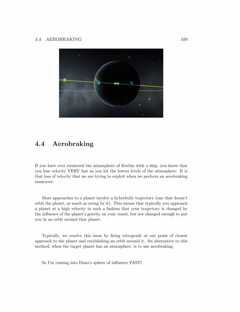
4.4. AEROBRAKING 109
4.4 Aerobraking
If you have ever reentered the atmosphere of Kerbin with a ship, you know thatyou lose velocity VERY fast as you hit the lowers levels of the atmosphere. It isthat loss of velocity that we are trying to exploit when we perform an aerobrakingmaneuver.
Most approaches to a planet involve a hyberbolic trajectory (one that doesn’torbit the planet, as much as swing by it). This means that typically you approacha planet at a high velocity in such a fashion that your trajectory is changed bythe influence of the planet’s gravity on your vessel, but not changed enough to putyou in an orbit around that planet.
Typically, we resolve this issue by firing retrograde at our point of closestapproach to the planet and establishing an orbit around it. An alternative to thismethod, when the target planet has an atmosphere, is to use aerobraking.
So I’m coming into Duna’s sphere of influence FAST!

110 CHAPTER 4. ORBITAL MANEUVERS
WAAAYYYY before I get there, I adjusted my trajectory so that my periapsisaround Duna, on arrival, is in the atmosphere. Duna’s atmosphere extends 41,447meters from the surface. As you can see in the picture below, even though Iam 29+ DAYS away from reaching Duna, I’ve already established a periapsis of∼24,000 meters. I’m going to adjust this further to be around 12,000 meters formaximum aerobraking effect.

4.4. AEROBRAKING 111
As soon as I reach Duna’s sphere of influence (SoI), I now see that my periapsisis 89,569 meters. This is because the estimate that I was shown, before actuallygetting there, was slightly off.
One last final adjustment to my periapsis using RCS, because the engine wouldbe WAY too powerful for this minute adjustment.
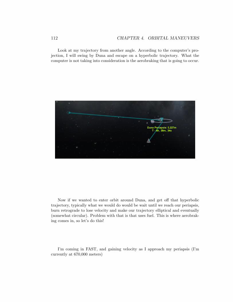
112 CHAPTER 4. ORBITAL MANEUVERS
Look at my trajectory from another angle. According to the computer’s pro-jection, I will swing by Duna and escape on a hyperbolic trajectory. What thecomputer is not taking into consideration is the aerobraking that is going to occur.
Now if we wanted to enter orbit around Duna, and get off that hyperbolictrajectory, typically what we would do would be wait until we reach our periapsis,burn retrograde to lose velocity and make our trajectory elliptical and eventually(somewhat circular). Problem with that is that uses fuel. This is where aerobrak-ing comes in, so let’s do this!
I’m coming in FAST, and gaining velocity as I approach my periapsis (I’mcurrently at 670,000 meters)

4.4. AEROBRAKING 113
50,000 meters, going 1500+ m/s. Hang on cuz here we go!
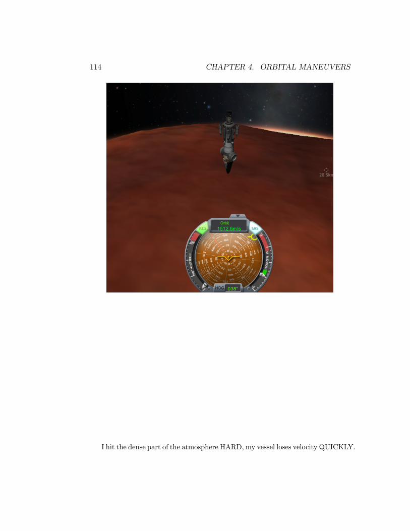
114 CHAPTER 4. ORBITAL MANEUVERS
I hit the dense part of the atmosphere HARD, my vessel loses velocity QUICKLY.

4.4. AEROBRAKING 115
Enough so that my hyberbolic trajectory
is now transformed into a highly elliptical orbit around Duna.

116 CHAPTER 4. ORBITAL MANEUVERS
And still losing speed, lowering my apoapsis even more
I zip through Duna’s atmosphere, losing a lot of my velocity, but not enoughto actually land, and come out the other side of the atmosphere still moving at agood clip.

4.4. AEROBRAKING 117
My apoapsis is now high above Duna
When I hit it my apoapsis, I can thrust prograde, very little, just to lift myperiapsis out of the denser part of the atmosphere, but still leave it inside the

118 CHAPTER 4. ORBITAL MANEUVERS
atmosphere. We don’t want to do another hardcore aerobraking session like thelast one, but we still want to use the atmosphere to lower our apoapsis some more.
I come around to my periapsis a second time and my apoapsis drops somemore due to the aerobraking.
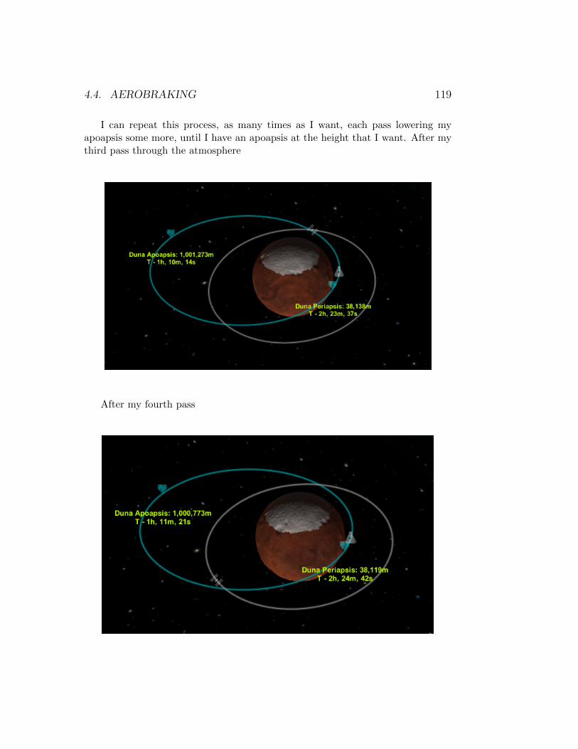
4.4. AEROBRAKING 119
I can repeat this process, as many times as I want, each pass lowering myapoapsis some more, until I have an apoapsis at the height that I want. After mythird pass through the atmosphere
After my fourth pass
120 CHAPTER 4. ORBITAL MANEUVERS
And I can continue orbiting Duna for as long as I want, each pass, in thiscase, lowering my apoapsis by only 500 meters. That’s pretty precise control. IfI wanted to lower it faster, just dip my periapsis further into the atmosphere; if Iwant to lower it slower, lift my periapsis a little bit more up in the atmosphere.
Once I’m at the height that I want, I can thrust prograde at my apoapsis tobring my periapsis completely out of the atmosphere and circularize into a stableorbit.
Or I can even let it go all the way until my apoapsis also falls into the atmo-sphere, making my trajectory sub-orbital, and I can then (try to) land.
4.4. AEROBRAKING 121
And there you have it, I successfully established an orbit around Duna (orlanded on Duna, depending on which scenario you followed above), while expend-ing very little (or no) ∆v. The amount expended would be typically less than anyminor orbital correction that you might make on a typical mission. All thanksto aerobraking. Unfortunately, this maneuver only works on planets that have anatmosphere, but the ”larger” and denser the atmosphere, the better it works!
Let’s do the math for the above maneuver: When I first entered Duna’s SoI,I used RCS (about 2.2 m/s worth) to readjust my periapsis; after my first tripthrough the atmosphere, I burn 9.2 m/s worth of ∆v to lift my periapsis almostout of the atmosphere; after A LOT of orbits, I finally used 56.5 m/s of ∆v tocircularize my final orbit. If I went for the landing scenario, don’t count that last56.5 m/s.
To summarize:

122 CHAPTER 4. ORBITAL MANEUVERS
• Establish 150,000 meter orbit around Duna using aerobraking: 67.9 m/s of∆v
• To land on Duna, using aerobraking: 11.4 m/s of ∆v
With those kinds of budget, you don’t even need an engine! You could do thewhole thing with RCS!
4.5 Rendezvous
Here’s the setup. . . I have one ship orbiting Kerbin at an altitude of 1,000,000meters. It has an orbital inclination of 45°. The second ship is in a 500,000 meterequatorial orbit (inclination of 0°). The blue orbit in the picture below is the shipat 500,000 meters. The yellow orbit is the ship with which I want to rendezvous.
This is going to make this section longer, but I did it for two reasons:
4.5. RENDEZVOUS 123
• With this inclination and altitude, I avoid falling behind Kerbin’s shadow,so the screenshots should be better.
• This will give me the opportunity to show how you incorporate an inclinationchange into your rendezvous process.
Make sure you click on your target ship and select ”Set as Target” (this is whatmakes the orbit yellow, and shows you the ascending and descending nodes).
The first thing we want to do is match planes. At the Ascending Node in myorbit

124 CHAPTER 4. ORBITAL MANEUVERS
I create a maneuver node and adjust by pulling the anti-normal indicator (pinktriangle with ”spikes”) down until I have about half the plane change done.

4.5. RENDEZVOUS 125
If I look at my proposed orbit from another angle, you’ll notice that the apoap-sis raised significantly
126 CHAPTER 4. ORBITAL MANEUVERS
I can pull the retrograde marker a little to bring that back, if I want, but we’regoing to need to do something like that anyway (since it’s almost exactly at the1,000,000 meter mark) so I’ll just leave it.
Let’s execute this node:
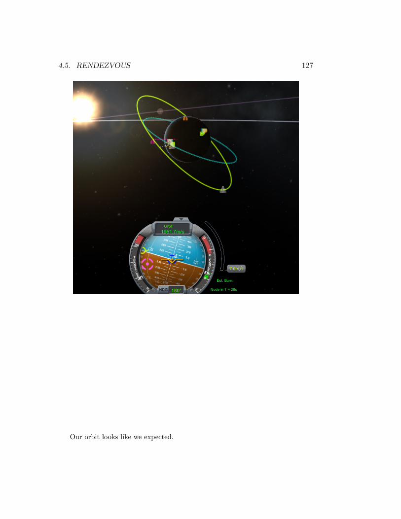
4.5. RENDEZVOUS 127
Our orbit looks like we expected.
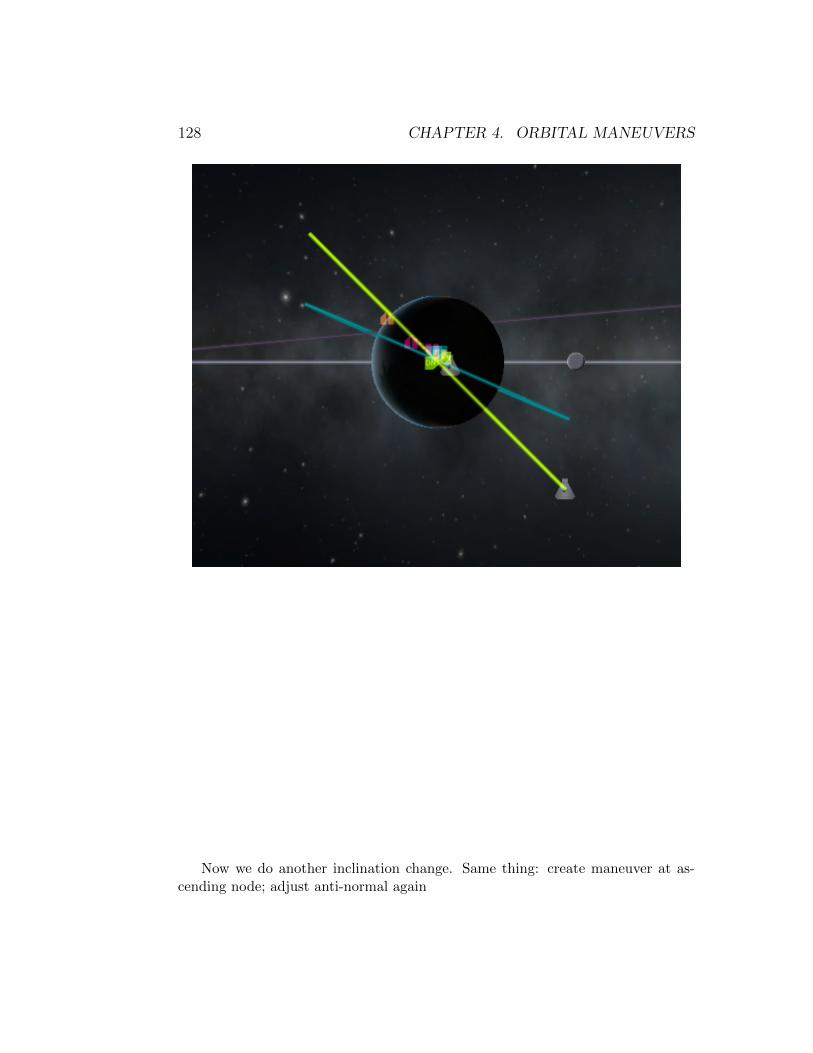
128 CHAPTER 4. ORBITAL MANEUVERS
Now we do another inclination change. Same thing: create maneuver at as-cending node; adjust anti-normal again
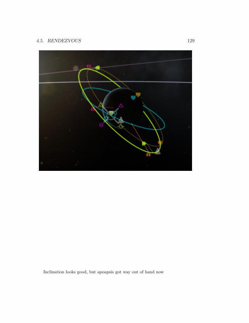
4.5. RENDEZVOUS 129
Inclination looks good, but apoapsis got way out of hand now

130 CHAPTER 4. ORBITAL MANEUVERS
So let’s adjust the retrograde marker of the maneuver node and bring thatback
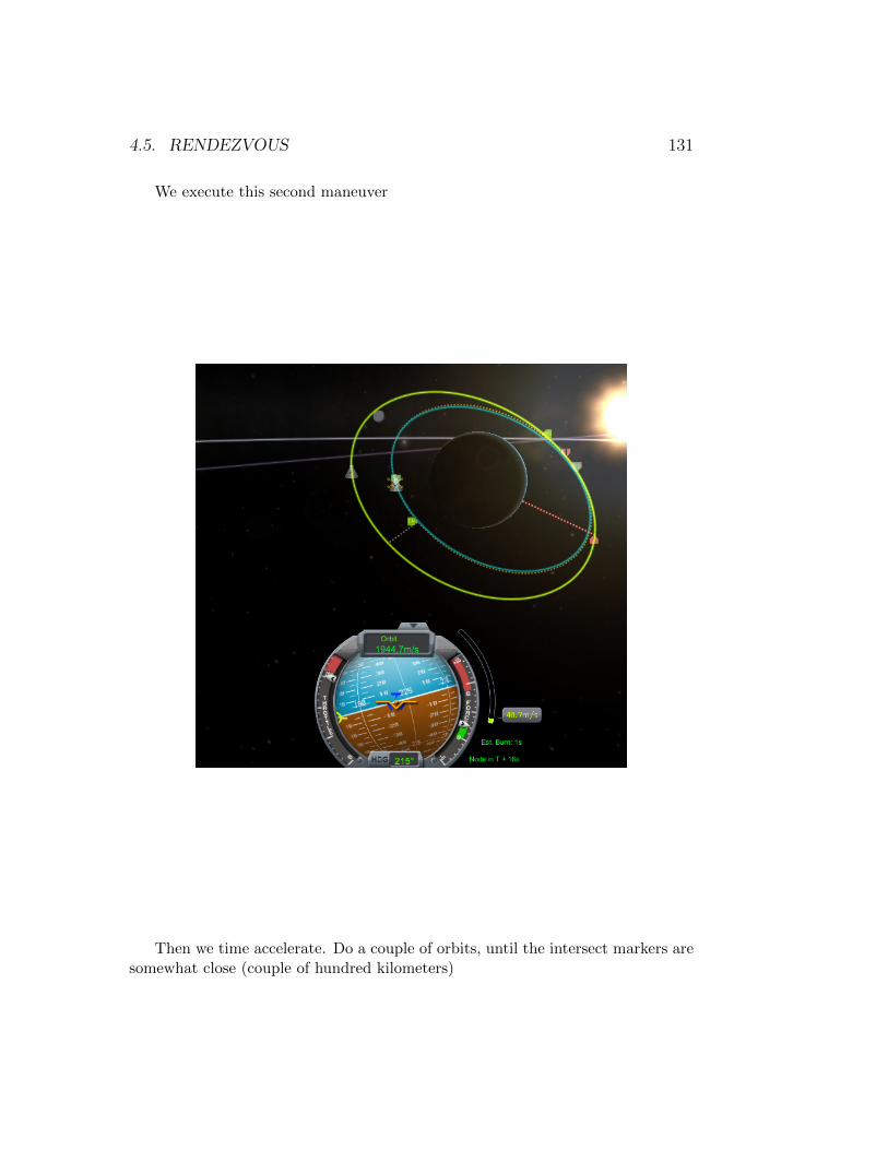
4.5. RENDEZVOUS 131
We execute this second maneuver
Then we time accelerate. Do a couple of orbits, until the intersect markers aresomewhat close (couple of hundred kilometers)

132 CHAPTER 4. ORBITAL MANEUVERS
Now create a maneuver node about 14 of an orbit BEFORE the intersect
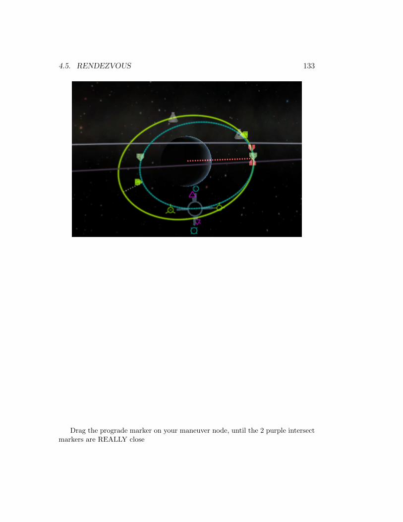
4.5. RENDEZVOUS 133
Drag the prograde marker on your maneuver node, until the 2 purple intersectmarkers are REALLY close
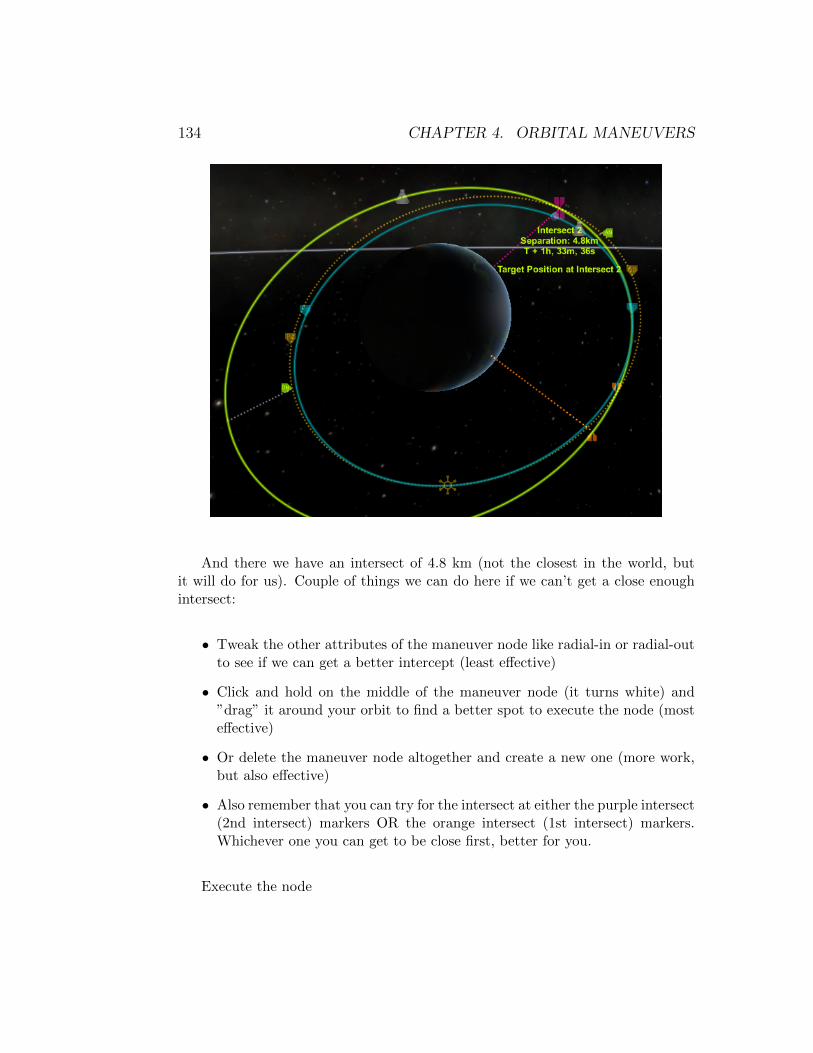
134 CHAPTER 4. ORBITAL MANEUVERS
And there we have an intersect of 4.8 km (not the closest in the world, butit will do for us). Couple of things we can do here if we can’t get a close enoughintersect:
• Tweak the other attributes of the maneuver node like radial-in or radial-outto see if we can get a better intercept (least effective)
• Click and hold on the middle of the maneuver node (it turns white) and”drag” it around your orbit to find a better spot to execute the node (mosteffective)
• Or delete the maneuver node altogether and create a new one (more work,but also effective)
• Also remember that you can try for the intersect at either the purple intersect(2nd intersect) markers OR the orange intersect (1st intersect) markers.Whichever one you can get to be close first, better for you.
Execute the node
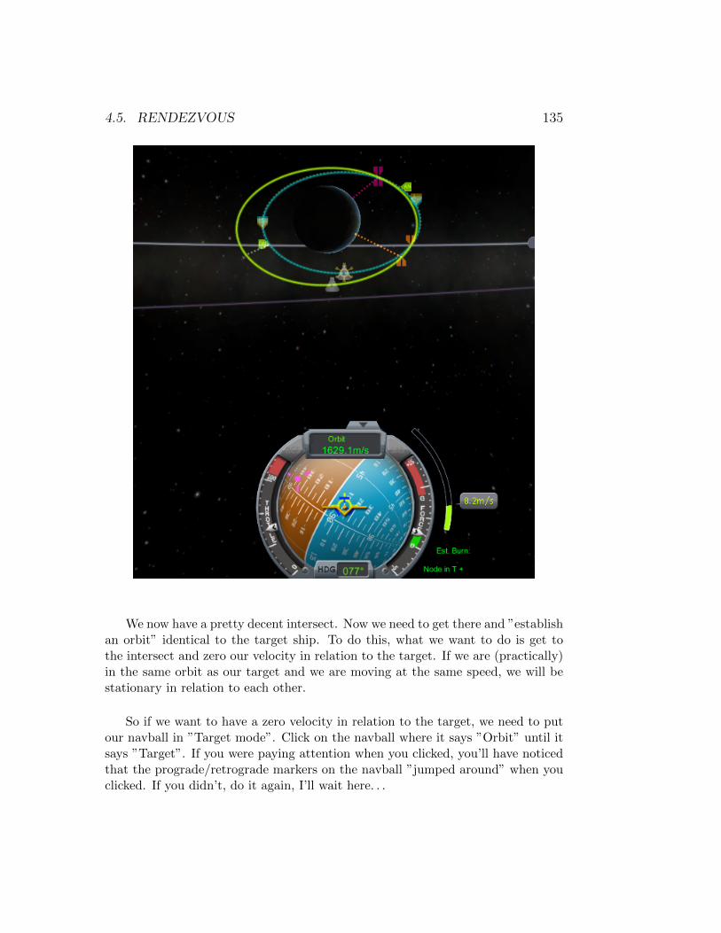
4.5. RENDEZVOUS 135
We now have a pretty decent intersect. Now we need to get there and ”establishan orbit” identical to the target ship. To do this, what we want to do is get tothe intersect and zero our velocity in relation to the target. If we are (practically)in the same orbit as our target and we are moving at the same speed, we will bestationary in relation to each other.
So if we want to have a zero velocity in relation to the target, we need to putour navball in ”Target mode”. Click on the navball where it says ”Orbit” until itsays ”Target”. If you were paying attention when you clicked, you’ll have noticedthat the prograde/retrograde markers on the navball ”jumped around” when youclicked. If you didn’t, do it again, I’ll wait here. . .
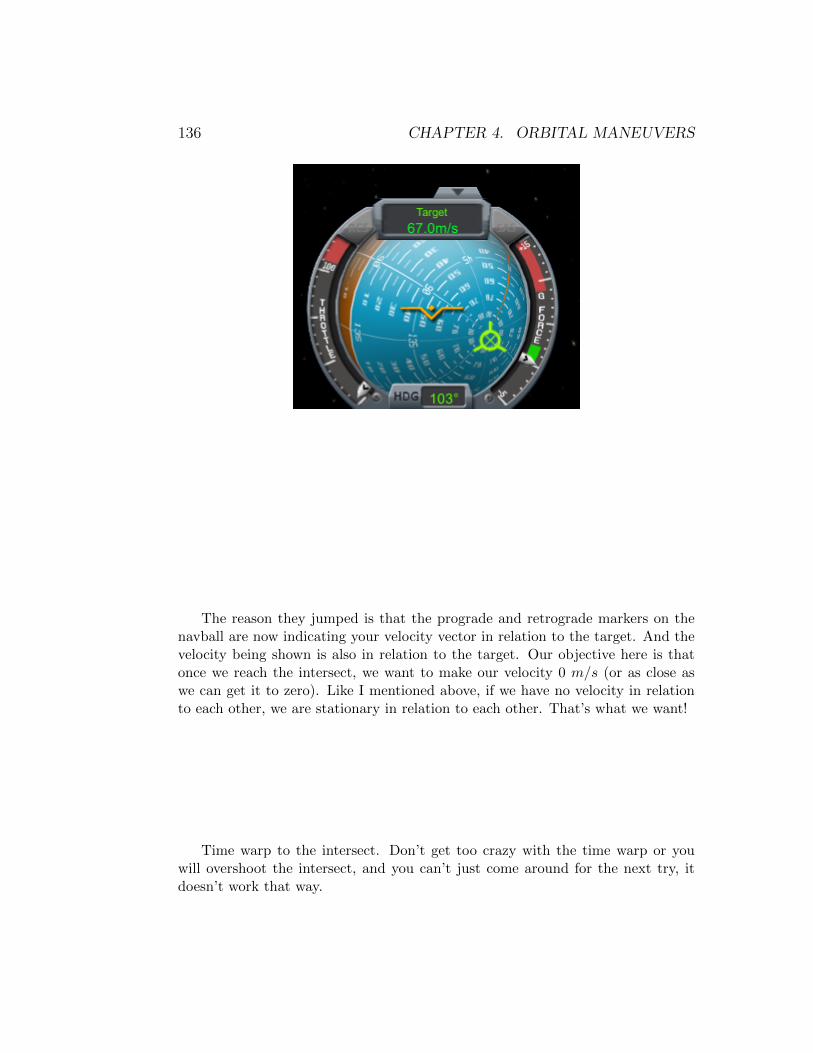
136 CHAPTER 4. ORBITAL MANEUVERS
The reason they jumped is that the prograde and retrograde markers on thenavball are now indicating your velocity vector in relation to the target. And thevelocity being shown is also in relation to the target. Our objective here is thatonce we reach the intersect, we want to make our velocity 0 m/s (or as close aswe can get it to zero). Like I mentioned above, if we have no velocity in relationto each other, we are stationary in relation to each other. That’s what we want!
Time warp to the intersect. Don’t get too crazy with the time warp or youwill overshoot the intersect, and you can’t just come around for the next try, itdoesn’t work that way.

4.5. RENDEZVOUS 137
Notice that as we pass the orange intersect markers (1st intersect) on the orbit,the purple ones (2nd intersect) turn orange, since what was our 2nd intersect nowbecame our 1st intersect.

138 CHAPTER 4. ORBITAL MANEUVERS
Once we are near the intersect (notice how I’m ∼1 minute away from theintersect)

4.5. RENDEZVOUS 139
Point retrograde on your navball and turn on SAS ( t key). Time your burnso that you have enough time to bleed off the speed that you have in relation to thetarget (in my case, 223.4 m/s). Let’s call it 25 seconds. So when I’m 25 secondsfrom the intersect I will activate my engines.
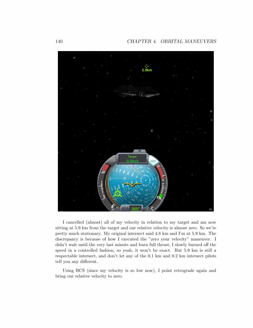
140 CHAPTER 4. ORBITAL MANEUVERS
I cancelled (almost) all of my velocity in relation to my target and am nowsitting at 5.9 km from the target and our relative velocity is almost zero. So we’repretty much stationary. My original intersect said 4.8 km and I’m at 5.9 km. Thediscrepancy is because of how I executed the ”zero your velocity” maneuver. Ididn’t wait until the very last minute and burn full thrust, I slowly burned off thespeed in a controlled fashion, so yeah, it won’t be exact. But 5.9 km is still arespectable intersect, and don’t let any of the 0.1 km and 0.2 km intersect pilotstell you any different.
Using RCS (since my velocity is so low now), I point retrograde again andbring our relative velocity to zero.
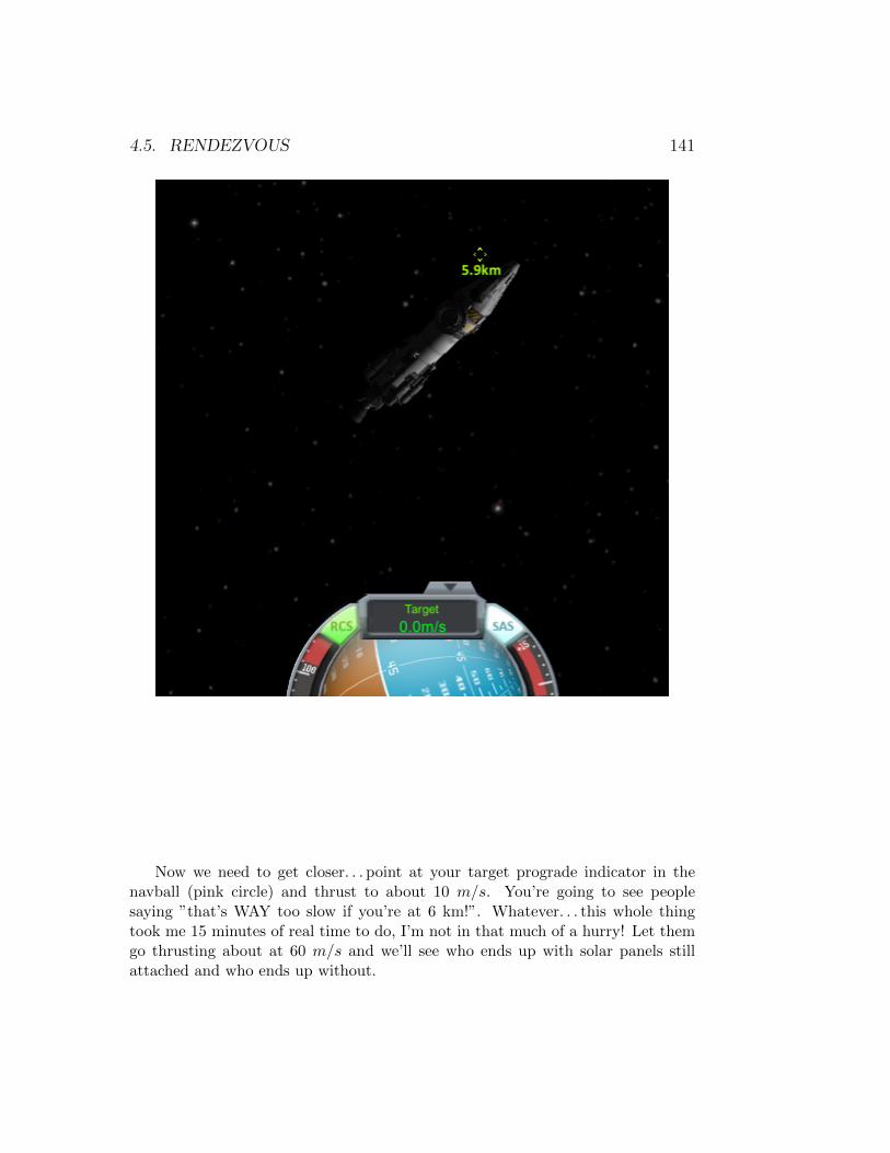
4.5. RENDEZVOUS 141
Now we need to get closer. . . point at your target prograde indicator in thenavball (pink circle) and thrust to about 10 m/s. You’re going to see peoplesaying ”that’s WAY too slow if you’re at 6 km!”. Whatever. . . this whole thingtook me 15 minutes of real time to do, I’m not in that much of a hurry! Let themgo thrusting about at 60 m/s and we’ll see who ends up with solar panels stillattached and who ends up without.
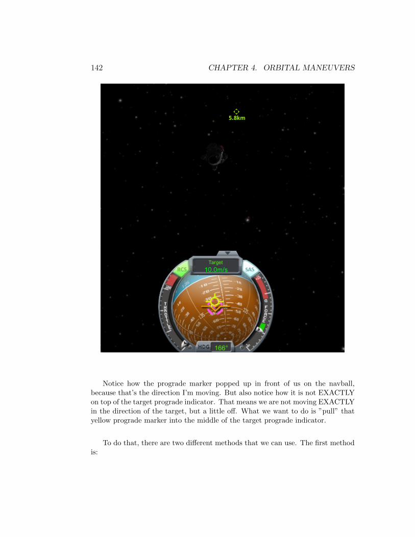
142 CHAPTER 4. ORBITAL MANEUVERS
Notice how the prograde marker popped up in front of us on the navball,because that’s the direction I’m moving. But also notice how it is not EXACTLYon top of the target prograde indicator. That means we are not moving EXACTLYin the direction of the target, but a little off. What we want to do is ”pull” thatyellow prograde marker into the middle of the target prograde indicator.
To do that, there are two different methods that we can use. The first methodis:

4.5. RENDEZVOUS 143
• point to the spot that is almost exactly opposite of the yellow progrademarker on the other side of the target prograde marker
See how I’m pointed to almost the exact opposite position, compared to theyellow prograde, except on the other side of the target prograde marker? Use RCS

144 CHAPTER 4. ORBITAL MANEUVERS
forward ( h key) to thrust in that direction A LITTLE BIT to pull the yellowprograde marker where you want it. Wherever you are pointing when you thrustis where the prograde marker is going to move towards.
I screwed that one up, on purpose. See how my prograde is now to the rightof my target? Point to the left of the target and thrust there
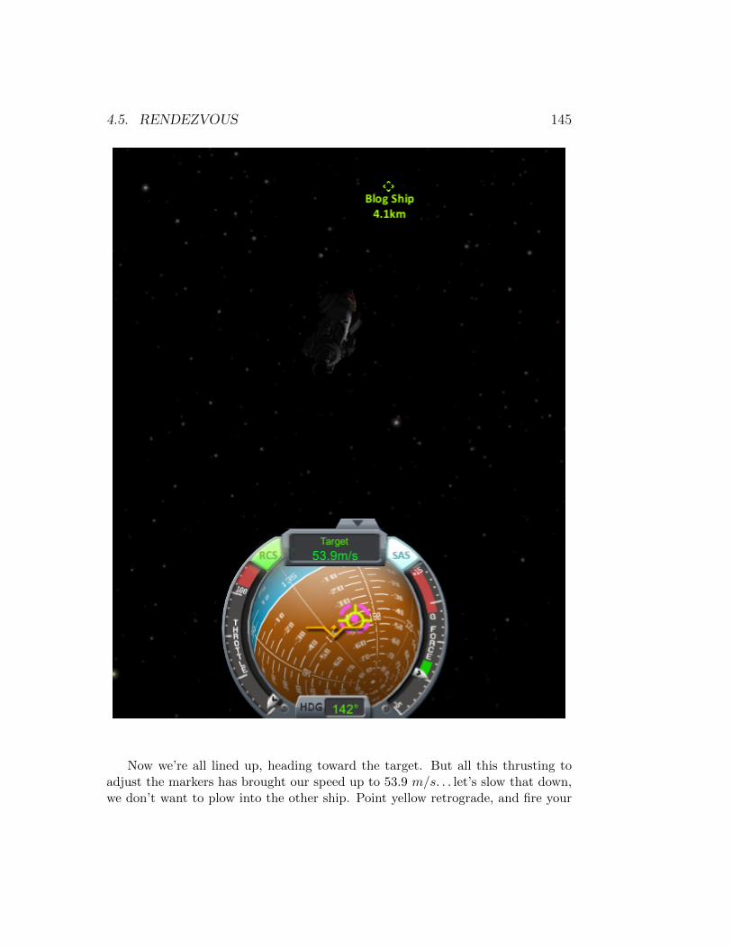
4.5. RENDEZVOUS 145
Now we’re all lined up, heading toward the target. But all this thrusting toadjust the markers has brought our speed up to 53.9 m/s. . . let’s slow that down,we don’t want to plow into the other ship. Point yellow retrograde, and fire your
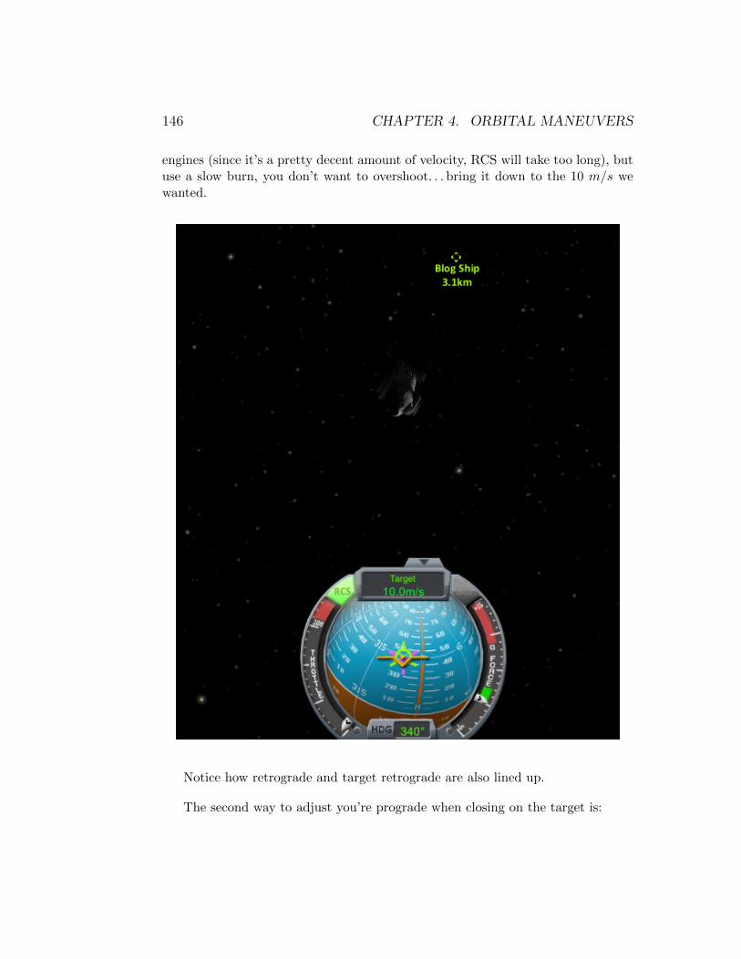
146 CHAPTER 4. ORBITAL MANEUVERS
engines (since it’s a pretty decent amount of velocity, RCS will take too long), butuse a slow burn, you don’t want to overshoot. . . bring it down to the 10 m/s wewanted.
Notice how retrograde and target retrograde are also lined up.
The second way to adjust you’re prograde when closing on the target is:
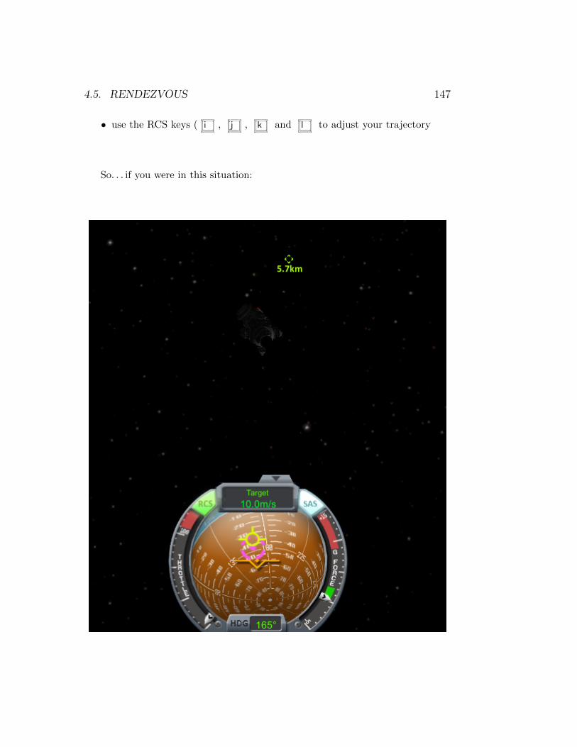
4.5. RENDEZVOUS 147
• use the RCS keys ( i , j , k and l to adjust your trajectory
So. . . if you were in this situation:
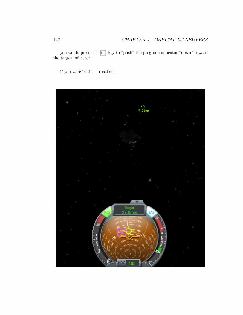
148 CHAPTER 4. ORBITAL MANEUVERS
you would press the i key to ”push” the prograde indicator ”down” towardthe target indicator
if you were in this situation:

4.5. RENDEZVOUS 149
you would use the j key to ”push” the prograde indicator ”left” toward thetarget indicator.
One of the big advantages of the second method is that you will not end upwith your closing speed as high as the first method (53.9 m/s), which can be veryimportant if you are closing from a smaller distance. At smaller distances, youdon’t want to end up accelerating too much toward your target, or bad things willhappen.
So. . . whatever method you use, eveything should be lined up and you shouldbe approaching your target at a reasonable speed. . .
If it’s taking too long to get to the target, DO NOT ACCELERATEMORE! Use time warp. I’m not saying you have to only do rendezvous at 10m/s, what I’m saying is: find a velocity you are comfortable with and stay there.Don’t adjust your velocity to speed things up. Use time warp, because once youare REALLY close, you can instantly leave time warp. If you accelerated to makethings go faster, when you are REALLY close, you CAN’T instantly slow down(gotta point in the right direction, fire engines or RCS, be careful not to overshoot,etc.). It’s a lot harder to do that ”on-the-fly” when you are 20 meters from yourtarget and going too fast!
Depending on how well aligned you managed to get those two markers, theywill tend to drift as you get close to your target (I did pretty good actually, theyonly drifted a tiny bit and I’m already at 196 m). If they drift, use the sameprocess you used to align them initially, to realign them.
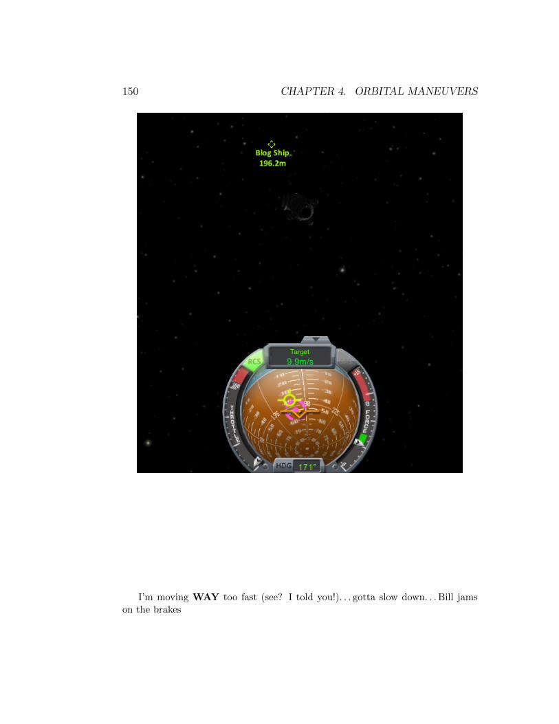
150 CHAPTER 4. ORBITAL MANEUVERS
I’m moving WAY too fast (see? I told you!). . . gotta slow down. . . Bill jamson the brakes
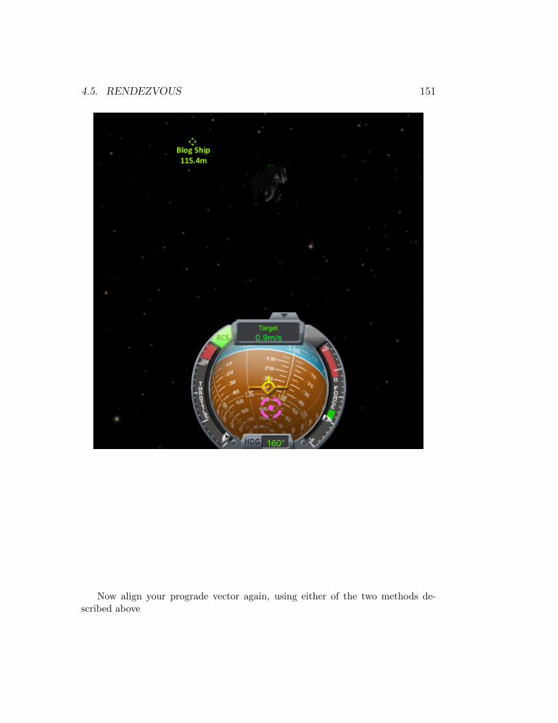
4.5. RENDEZVOUS 151
Now align your prograde vector again, using either of the two methods de-scribed above

152 CHAPTER 4. ORBITAL MANEUVERS
A little bit of time warping and here we are, up close and personal, with ourtarget ship. 12 meters is not bad to start a docking procedure, but we’ll do thatin the next section.

4.5. RENDEZVOUS 153
Before wrapping up, some other tips to discuss:
• When trying to adjust your velocity, if the change is small (less than 5-10m/s), use RCS.
• Using RCS forward ( h key) is the same as using your engines to thrustvery slowly in the direction you are pointing. This is sometimes exactly whatyou want/need: very fine adjustments. Likewise, RCS backwards ( n key)is very useful for reducing your velocity without having to do ”space-flips”(see below).
• If you are pointing prograde and want to reduce your velocity, it is moreefficient to STAY pointing prograde, and thrust RCS backwards ( n key)than to flip 180° and thrust forward and then have to flip 180° again. Itwill save RCS monopropellant and even if you are only using torque toturn around, it’s still a lot faster to thrust backwards than to flip around.
154 CHAPTER 4. ORBITAL MANEUVERS
Obviously, this doesn’t apply if you have to make a significant change in yourvelocity (requiring engines), since engines don’t thrust backwards (unless youmount a set facing forward on your craft, there’s nothing to say you can’t!).
• Ditto if you are pointing retrograde, but need to increase your velocity. Justthrust backwards, same concept.
• Another adjustment you can make, similar to the two above. If we want to”pull” the yellow prograde we thrust forward after pointing in the appropri-ate direction. But if we overshoot our target prograde indicator (we ”pulled”it too much), you don’t have to turn and adjust again. Just thrust backwards(assuming you are using RCS), if thrusting forwards ”pulls” the prograde,thrusting backwards ”pushes” it away from wherever you are pointing!
• Always try to be as precise as possible when positioning the yellow progradevector over your target prograde vector. The more precise you are, the lessadjustments you will have to make to your trajectory as you get closer.
• In my example above, I was only pointing a little off the target indicator,to illustrate the point, but you can point further away and use less thrustto achieve the same correction. I only did not do that because if I pointed90° away from the target prograde indicator, it wouldn’t have been visibleon my navball and my explanation would be vague. Just make sure thatthe vector you are pointing is correct (if yellow prograde is to the left, youpoint to the right; if yellow prograde is above, you point below; etc) for theadjustment you want to make.
• And finally, keep your velocity in check. Those darn solar panels are attachedwith bubble gum and will fall off at the slightest nudge! Use time warpingliberally during rendezvous. Use it a lot, but not high time warps otherwisedebris will happen!
Just so you have an idea of how hard this was: Even with making sure totake all the screenshots at the right times, actual play time from the very firstscreenshot to the very last screenshot in this section, was about 15 minutes realtime. Game time was a lot more than that due to the time warping (especiallywhen I was waiting for that ∼200 km intersect). All maneuver nodes were createdmanually, no MechJebbing any of them. I did Hyperedit both of those ships intotheir initial positions, but that was it. Infinite fuel was on (but probably didn’tneed to be).
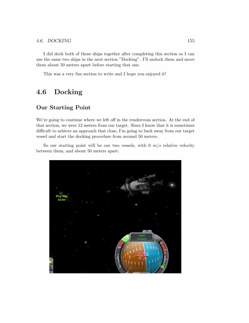
4.6. DOCKING 155
I did dock both of those ships together after completing this section so I canuse the same two ships in the next section ”Docking”. I’ll undock them and movethem about 50 meters apart before starting that one.
This was a very fun section to write and I hope you enjoyed it!
4.6 Docking
Our Starting Point
We’re going to continue where we left off in the rendezvous section. At the end ofthat section, we were 12 meters from our target. Since I know that it is sometimesdifficult to achieve an approach that close, I’m going to back away from our targetvessel and start the docking procedure from around 50 meters.
So our starting point will be our two vessels, with 0 m/s relative velocitybetween them, and about 50 meters apart.
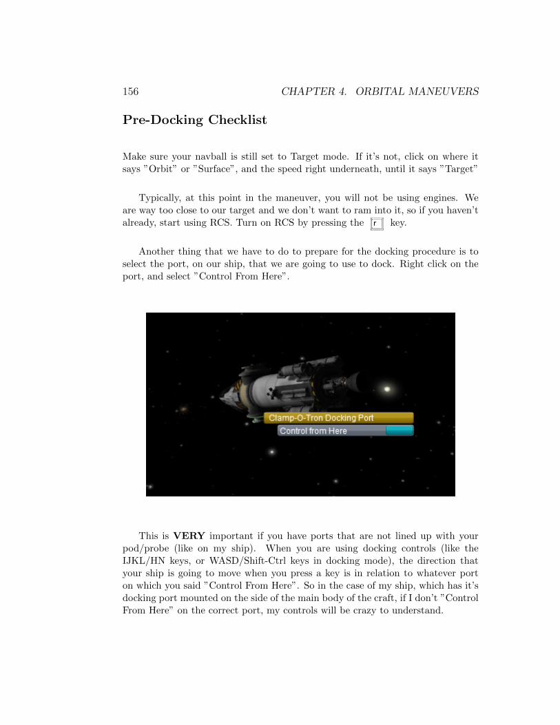
156 CHAPTER 4. ORBITAL MANEUVERS
Pre-Docking Checklist
Make sure your navball is still set to Target mode. If it’s not, click on where itsays ”Orbit” or ”Surface”, and the speed right underneath, until it says ”Target”
Typically, at this point in the maneuver, you will not be using engines. Weare way too close to our target and we don’t want to ram into it, so if you haven’talready, start using RCS. Turn on RCS by pressing the r key.
Another thing that we have to do to prepare for the docking procedure is toselect the port, on our ship, that we are going to use to dock. Right click on theport, and select ”Control From Here”.
This is VERY important if you have ports that are not lined up with yourpod/probe (like on my ship). When you are using docking controls (like theIJKL/HN keys, or WASD/Shift-Ctrl keys in docking mode), the direction thatyour ship is going to move when you press a key is in relation to whatever porton which you said ”Control From Here”. So in the case of my ship, which has it’sdocking port mounted on the side of the main body of the craft, if I don’t ”ControlFrom Here” on the correct port, my controls will be crazy to understand.
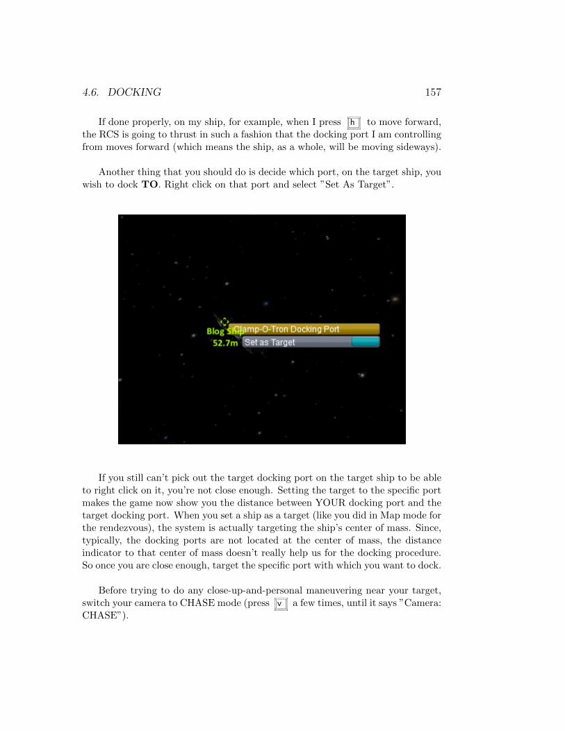
4.6. DOCKING 157
If done properly, on my ship, for example, when I press h to move forward,the RCS is going to thrust in such a fashion that the docking port I am controllingfrom moves forward (which means the ship, as a whole, will be moving sideways).
Another thing that you should do is decide which port, on the target ship, youwish to dock TO. Right click on that port and select ”Set As Target”.
If you still can’t pick out the target docking port on the target ship to be ableto right click on it, you’re not close enough. Setting the target to the specific portmakes the game now show you the distance between YOUR docking port and thetarget docking port. When you set a ship as a target (like you did in Map mode forthe rendezvous), the system is actually targeting the ship’s center of mass. Since,typically, the docking ports are not located at the center of mass, the distanceindicator to that center of mass doesn’t really help us for the docking procedure.So once you are close enough, target the specific port with which you want to dock.
Before trying to do any close-up-and-personal maneuvering near your target,switch your camera to CHASE mode (press v a few times, until it says ”Camera:CHASE”).
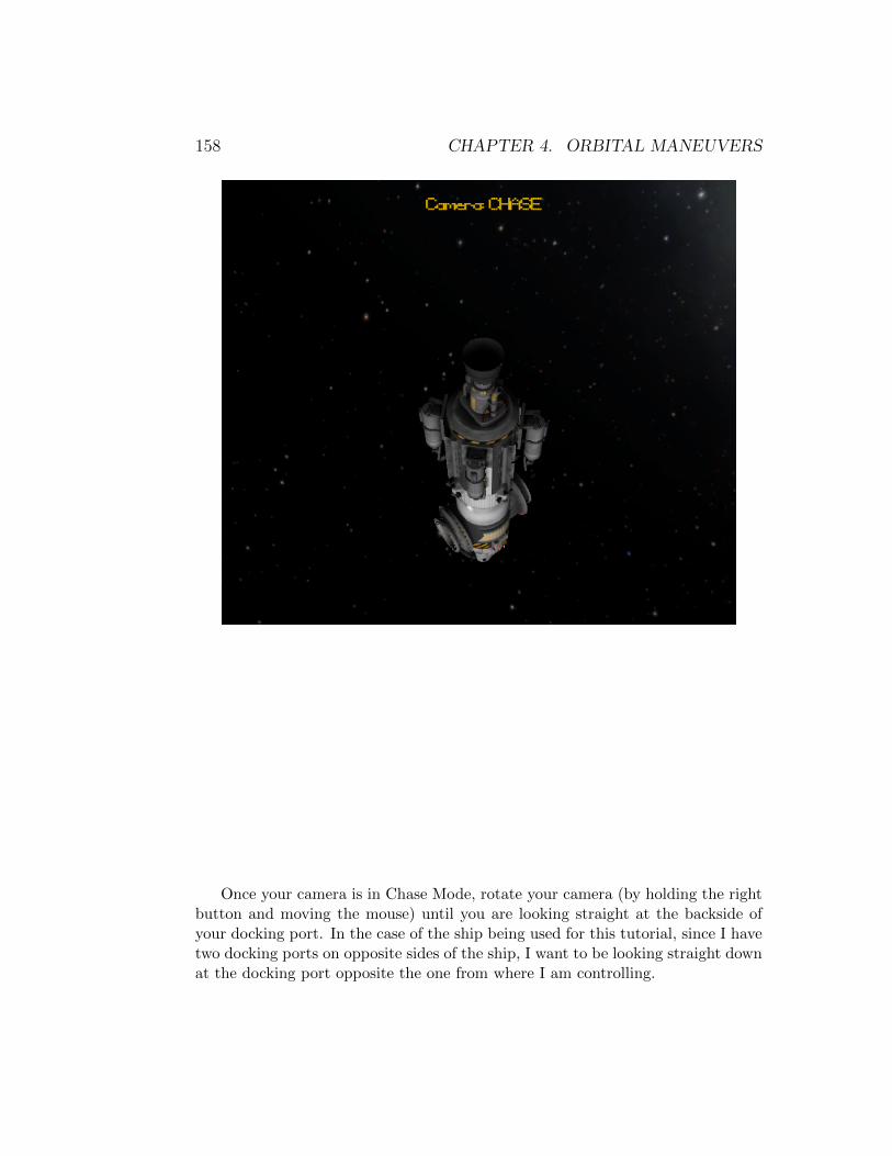
158 CHAPTER 4. ORBITAL MANEUVERS
Once your camera is in Chase Mode, rotate your camera (by holding the rightbutton and moving the mouse) until you are looking straight at the backside ofyour docking port. In the case of the ship being used for this tutorial, since I havetwo docking ports on opposite sides of the ship, I want to be looking straight downat the docking port opposite the one from where I am controlling.
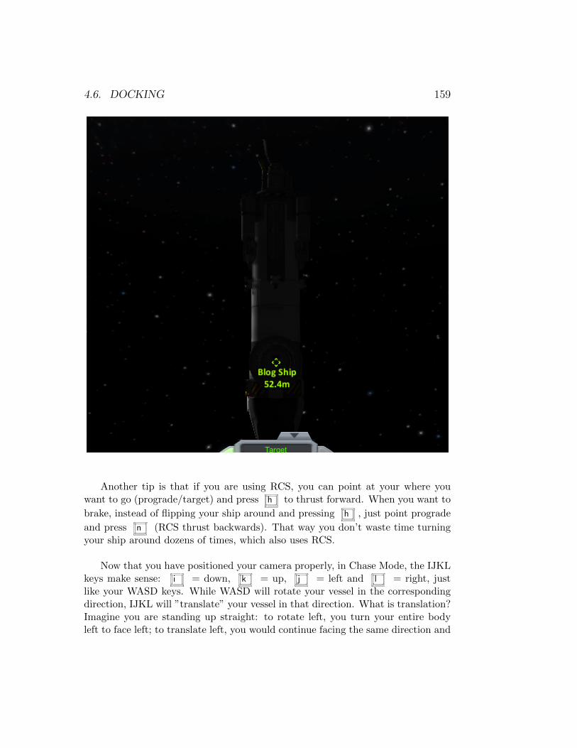
4.6. DOCKING 159
Another tip is that if you are using RCS, you can point at your where youwant to go (prograde/target) and press h to thrust forward. When you want to
brake, instead of flipping your ship around and pressing h , just point prograde
and press n (RCS thrust backwards). That way you don’t waste time turningyour ship around dozens of times, which also uses RCS.
Now that you have positioned your camera properly, in Chase Mode, the IJKLkeys make sense: i = down, k = up, j = left and l = right, justlike your WASD keys. While WASD will rotate your vessel in the correspondingdirection, IJKL will ”translate” your vessel in that direction. What is translation?Imagine you are standing up straight: to rotate left, you turn your entire bodyleft to face left; to translate left, you would continue facing the same direction and
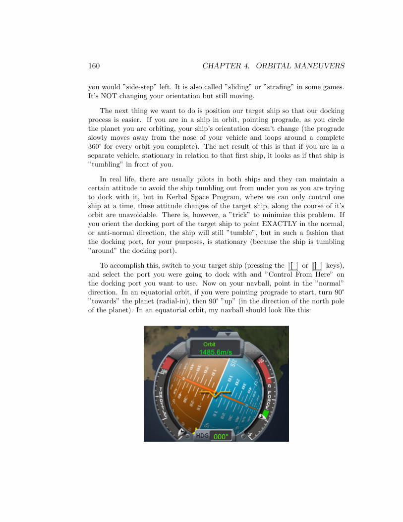
160 CHAPTER 4. ORBITAL MANEUVERS
you would ”side-step” left. It is also called ”sliding” or ”strafing” in some games.It’s NOT changing your orientation but still moving.
The next thing we want to do is position our target ship so that our dockingprocess is easier. If you are in a ship in orbit, pointing prograde, as you circlethe planet you are orbiting, your ship’s orientation doesn’t change (the progradeslowly moves away from the nose of your vehicle and loops around a complete360° for every orbit you complete). The net result of this is that if you are in aseparate vehicle, stationary in relation to that first ship, it looks as if that ship is”tumbling” in front of you.
In real life, there are usually pilots in both ships and they can maintain acertain attitude to avoid the ship tumbling out from under you as you are tryingto dock with it, but in Kerbal Space Program, where we can only control oneship at a time, these attitude changes of the target ship, along the course of it’sorbit are unavoidable. There is, however, a ”trick” to minimize this problem. Ifyou orient the docking port of the target ship to point EXACTLY in the normal,or anti-normal direction, the ship will still ”tumble”, but in such a fashion thatthe docking port, for your purposes, is stationary (because the ship is tumbling”around” the docking port).
To accomplish this, switch to your target ship (pressing the [ or ] keys),and select the port you were going to dock with and ”Control From Here” onthe docking port you want to use. Now on your navball, point in the ”normal”direction. In an equatorial orbit, if you were pointing prograde to start, turn 90°”towards” the planet (radial-in), then 90° ”up” (in the direction of the north poleof the planet). In an equatorial orbit, my navball should look like this:
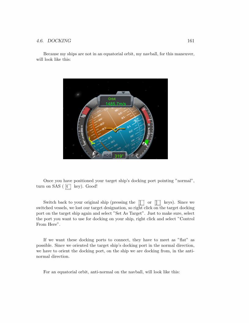
4.6. DOCKING 161
Because my ships are not in an equatorial orbit, my navball, for this maneuver,will look like this:
Once you have positioned your target ship’s docking port pointing ”normal”,turn on SAS ( t key). Good!
Switch back to your original ship (pressing the [ or ] keys). Since weswitched vessels, we lost our target designation, so right click on the target dockingport on the target ship again and select ”Set As Target”. Just to make sure, selectthe port you want to use for docking on your ship, right click and select ”ControlFrom Here”.
If we want these docking ports to connect, they have to meet as ”flat” aspossible. Since we oriented the target ship’s docking port in the normal direction,we have to orient the docking port, on the ship we are docking from, in the anti-normal direction.
For an equatorial orbit, anti-normal on the navball, will look like this:
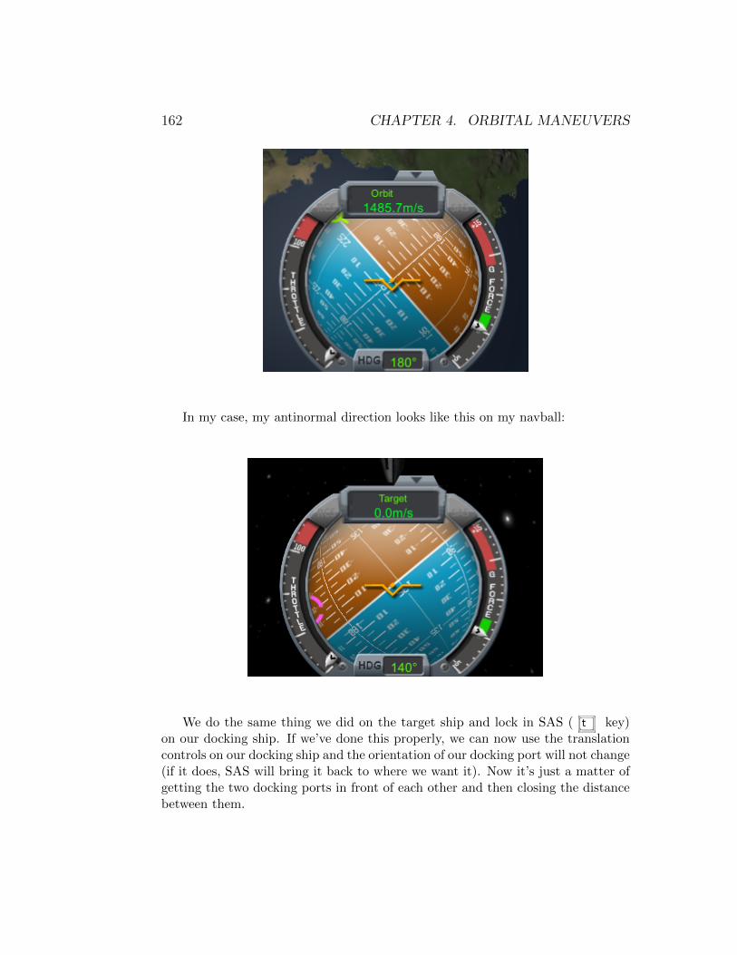
162 CHAPTER 4. ORBITAL MANEUVERS
In my case, my antinormal direction looks like this on my navball:
We do the same thing we did on the target ship and lock in SAS ( t key)on our docking ship. If we’ve done this properly, we can now use the translationcontrols on our docking ship and the orientation of our docking port will not change(if it does, SAS will bring it back to where we want it). Now it’s just a matter ofgetting the two docking ports in front of each other and then closing the distancebetween them.

4.6. DOCKING 163
Before we move on to docking these two ships I want to discuss the orientingof the ports to normal and anti-normal. If you are not in an equatorial orbit, itmight be difficult to figure out where those two points are on the navball. An easyway to figure that out is to create a ”dummy” maneuver node, and adjust as ifyou were performing a burn in the desired direction. Doesn’t matter how ”long”of a burn since you won’t be actually executing it.
Once you’ve created the node, there will be a maneuver node indicator on yournavball in the exact position that you need it. Orient your ship in that direction,engage SAS ( t key), and then you can delete the maneuver node.
This is where we currently stand, docking ports are aligned (orientation-wise)properly. and we’re still about 50 meters from our target. (I know this screenshotis horrible, but it was the best I could do. Trust me, they’re aligned in this picture).

164 CHAPTER 4. ORBITAL MANEUVERS
Docking
Before we actually start the docking process, let’s look at some tips on using RCS:
• Use RCS sparingly. . . if you are holding any given RCS thrust key for morethan 1 second, you’re doing it wrong! The closer you get, the shorter thebursts should be (really just quick taps on the keys).
• Learn the translation controls IJKL/HN as opposed to WASD/QE. Thatway you can leave the WASD keys to adjust orientation with your left hand(or just let SAS take care of rotation, if you set it as described above), whilestill translating using IJKL with your right hand.
• For the beginners (people who don’t have experience docking), only adjustone axis at a time. Example: use the I/K keys to adjust your ”up” and”down” position until your docking port is at the same height as the targetdocking port. Once you are done that part of the maneuver, your velocityin relation to the target should be 0 m/s (or as close as possible). THENstart using the J/L keys to adjust your ”left” and ”right” position until yourdocking port is aligned properly with the target docking port. When youare done with that part of the maneuver, again, your velocity in relationto the target should be 0 m/s. While this process consumes more RCSmonopropellant (instead of making a bee-line straight for the docking port),it is much easier to accomplish this way.
• Use time warping to accelerate the process. Don’t increase your speed tomuch over 0.1-0.3 m/s during the final approach. Example: you’re too”high” in relation to the target port: quick burst of RCS using the i key;your ship will start to slowly move down; If you’ve got 10-20 meters thatyou need to go down, time warp; once you are near perfect position, exittime warp; quick burst of RCS using the k key (to cancel out the initial
burst when you pressed the i key); you should now be stationary again;
The objective of our docking procedure is to make the two ports come intocontact as ”flat” as possible. We already know that the ports are currently ”flat”in relation to each other because of the pre-docking steps we took above.
Since we did the ”Control From Here” on the docking port we are using, thenavball is now oriented as if we were ”inside” the docking port, looking straightout. This is where our problem currently is:
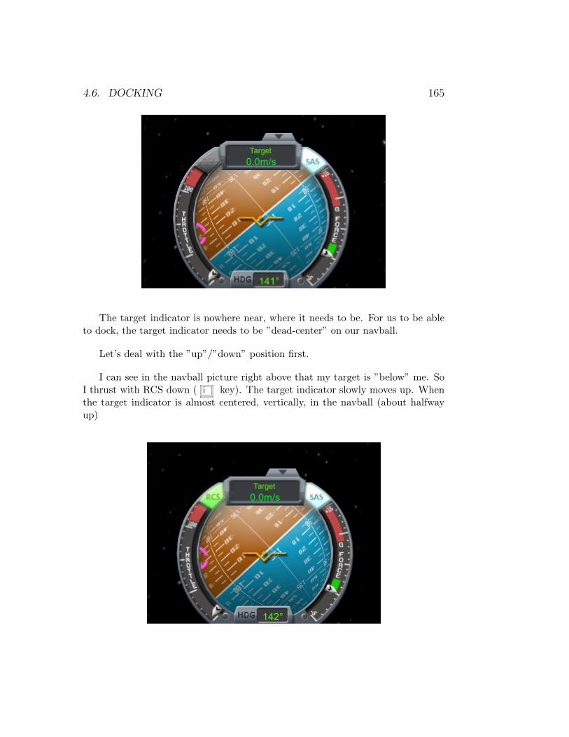
4.6. DOCKING 165
The target indicator is nowhere near, where it needs to be. For us to be ableto dock, the target indicator needs to be ”dead-center” on our navball.
Let’s deal with the ”up”/”down” position first.
I can see in the navball picture right above that my target is ”below” me. SoI thrust with RCS down ( i key). The target indicator slowly moves up. Whenthe target indicator is almost centered, vertically, in the navball (about halfwayup)
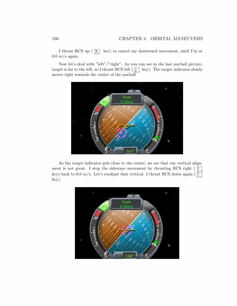
166 CHAPTER 4. ORBITAL MANEUVERS
I thrust RCS up ( k key) to cancel my downward movement, until I’m at0.0 m/s again.
Now let’s deal with ”left”/”right”. As you can see in the last navball picture,target is far to the left, so I thrust RCS left ( j key). The target indicator slowlymoves right towards the center of the navball
As the target indicator gets close to the center, we see that our vertical align-ment is not great. I stop the sideways movement by thrusting RCS right ( l
key) back to 0.0 m/s. Let’s readjust that vertical. I thrust RCS down again ( i
key).
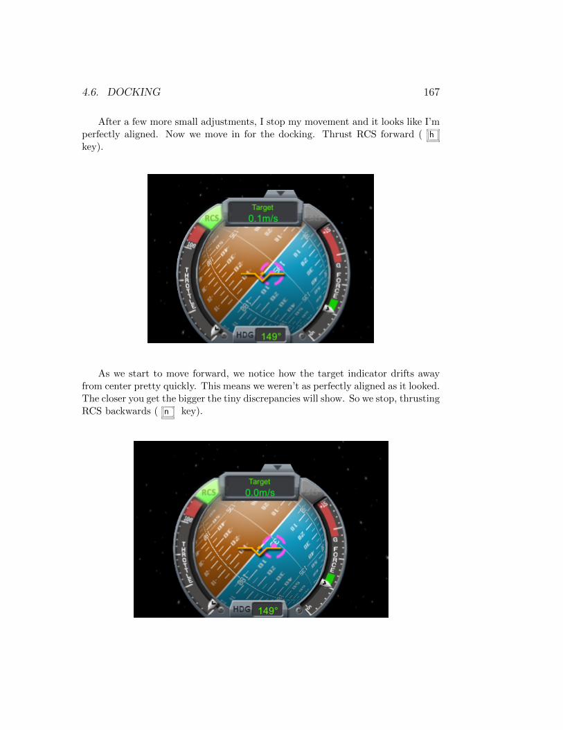
4.6. DOCKING 167
After a few more small adjustments, I stop my movement and it looks like I’mperfectly aligned. Now we move in for the docking. Thrust RCS forward ( h
key).
As we start to move forward, we notice how the target indicator drifts awayfrom center pretty quickly. This means we weren’t as perfectly aligned as it looked.The closer you get the bigger the tiny discrepancies will show. So we stop, thrustingRCS backwards ( n key).
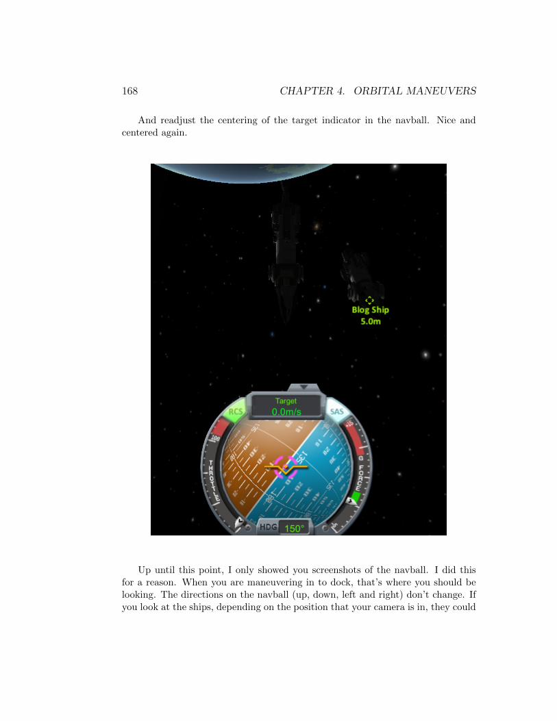
168 CHAPTER 4. ORBITAL MANEUVERS
And readjust the centering of the target indicator in the navball. Nice andcentered again.
Up until this point, I only showed you screenshots of the navball. I did thisfor a reason. When you are maneuvering in to dock, that’s where you should belooking. The directions on the navball (up, down, left and right) don’t change. Ifyou look at the ships, depending on the position that your camera is in, they could

4.6. DOCKING 169
be completely backwards. However, once you get really close (like the 5 metersI’m at now), you are pretty much docked and it’s just a matter of nudging themtogether, so at this point watch the ships.
Let’s try moving in again. . . h key. . .
As we move in, we very lightly control position using IJKL. TINY, TINYbursts. We’re at 3 meters. This might work! But I’m in the dark again, let merotate that camera so we can actually see this docking.
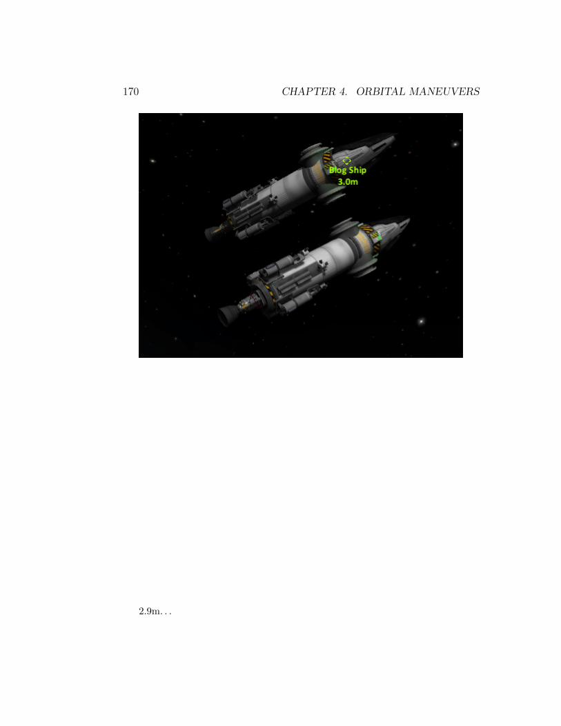
170 CHAPTER 4. ORBITAL MANEUVERS
2.9m. . .

4.6. DOCKING 171
2.7m. . .
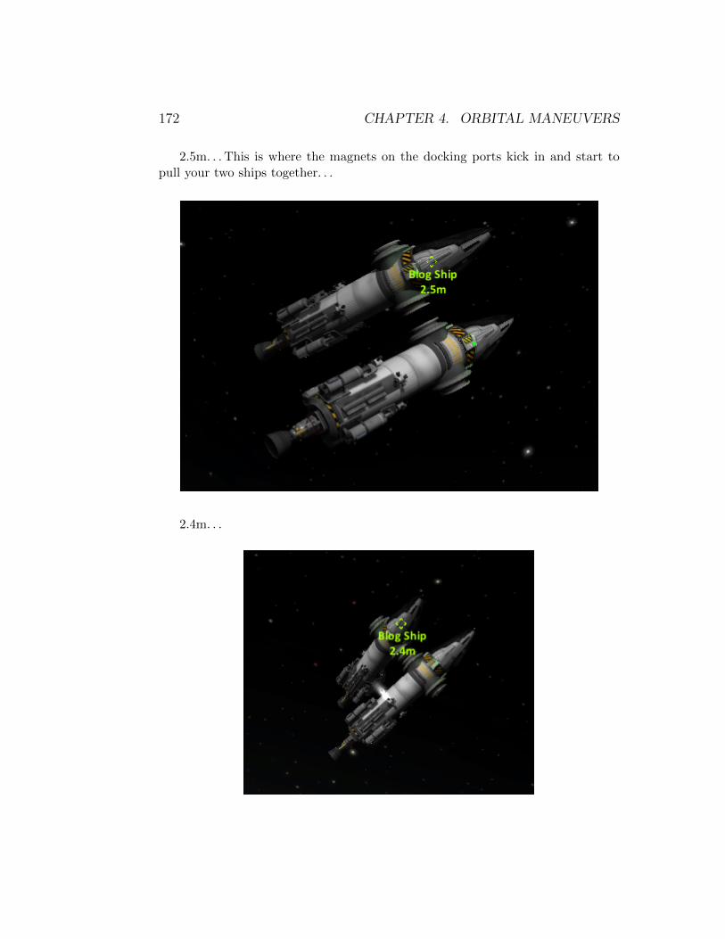
172 CHAPTER 4. ORBITAL MANEUVERS
2.5m. . . This is where the magnets on the docking ports kick in and start topull your two ships together. . .
2.4m. . .
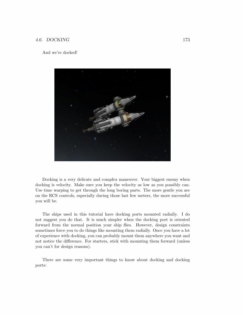
4.6. DOCKING 173
And we’re docked!
Docking is a very delicate and complex maneuver. Your biggest enemy whendocking is velocity. Make sure you keep the velocity as low as you possibly can.Use time warping to get through the long boring parts. The more gentle you areon the RCS controls, especially during those last few meters, the more successfulyou will be.
The ships used in this tutorial have docking ports mounted radially. I donot suggest you do that. It is much simpler when the docking port is orientedforward from the normal position your ship flies. However, design constraintssometimes force you to do things like mounting them radially. Once you have a lotof experience with docking, you can probably mount them anywhere you want andnot notice the difference. For starters, stick with mounting them forward (unlessyou can’t for design reasons).
There are some very important things to know about docking and dockingports:
174 CHAPTER 4. ORBITAL MANEUVERS
1. Docking ports must be the same size to dock to each other. You cannotdock a Clampotron Jr, to a regular sized Clampotron, or a regular sizedClampotron to a Clampotron Sr.
2. A very common mistake is putting the docking ports on backwards. This isespecially true of the Clampotron Srs. Whichever side is ”up” (in the VAB),or ”front” (in the SPH), when first picking the docking port from the partslist, is the side that actually docks. If you are not sure which side is up, grabthe part and press space in the VAB/SPH and that will reset the part’sorientation to as if you had just picked it from the parts list.
3. When docking ports are close enough together to dock, there is a magneticforce that they exert on each other to complete the docking, sometimeshaving SAS on when trying to dock, causes it to not dock. You can still useSAS during the docking maneuver, just make sure to turn it off for that lasthalf meter or so of approach.
4. When you undock two docking ports, the magnetic force mentioned above”turns off” to allow you to separate the two vessels without pulling themback together. The magnets only ”reset” if you move the docking ports acertain distance from each other (something like 5-10 meters). So if youjust undocked (usually to adjust a docking position) and can’t redock, trybacking away about 5-10 meters and THEN redocking. Some people havesaid that quick saving and quick loading also resets the magnets, I have notconfirmed this.
5. The ”Rockomax HubMax Multi-Point Connector” DOES NOT HAVEDOCKING PORTS ON IT!. If you want to dock to it, you HAVE toadd the docking port to it. Ditto for the ”BZ-52 Radial Attachment Point”.
6. The ”Inline Clamp-O-Tron” and the ”Clamp-O-Tron Shielded Docking Port”,on the other hand DO HAVE docking ports built into them. You have toright click the part to ”open” and expose the docking port once you havelaunched (can’t do the right clicking part during assembly).
I sincerely hope that this section helped you learn the fine art of docking!
4.7 Gravity Assist
A gravity assist, also known as: gravitational slingshot or swing-by, is a maneuverwhere a spacecraft approaches a planet, moon or other celestial body, and uses it’s
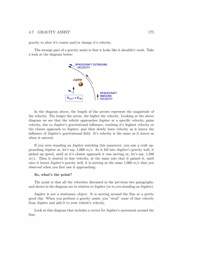
4.7. GRAVITY ASSIST 175
gravity to alter it’s course and/or change it’s velocity.
The strange part of a gravity assist is that it looks like it shouldn’t work. Takea look at the diagram below:
In the diagram above, the length of the arrows represent the magnitude ofthe velocity. The longer the arrow, the higher the velocity. Looking at the abovediagram we see that the vehicle approaches Jupiter at a specific velocity, gainsvelocity, due to Jupiter’s gravitational influence, reaching it’s highest velocity atthe closest approach to Jupiter, and then slowly loses velocity as it leaves theinfluence of Jupiter’s gravitational field. It’s velocity is the same as it leaves aswhen it entered.
If you were standing on Jupiter watching this maneuver, you saw a craft ap-proaching Jupiter at, let’s say, 1,000 m/s. As it fell into Jupiter’s gravity well, itpicked up speed, until at it’s closest approach it was moving at, let’s say, 1,500m/s. Then it started to lose velocity, at the same rate that it gained it, untilonce it leaves Jupiter’s gravity well, it is moving at the same 1,000 m/s that youobserved when you first saw it approaching.
So, what’s the point?
The point is that all the velocities discussed in the previous two paragraphs,and shown in the diagram are in relation to Jupiter (or to you standing on Jupiter).
Jupiter is not a stationary object. It is moving around the Sun at a prettygood clip. When you perform a gravity assist, you ”steal” some of that velocityfrom Jupiter and add it to your vehicle’s velocity.
Look at this diagram that includes a vector for Jupiter’s movement around theSun:
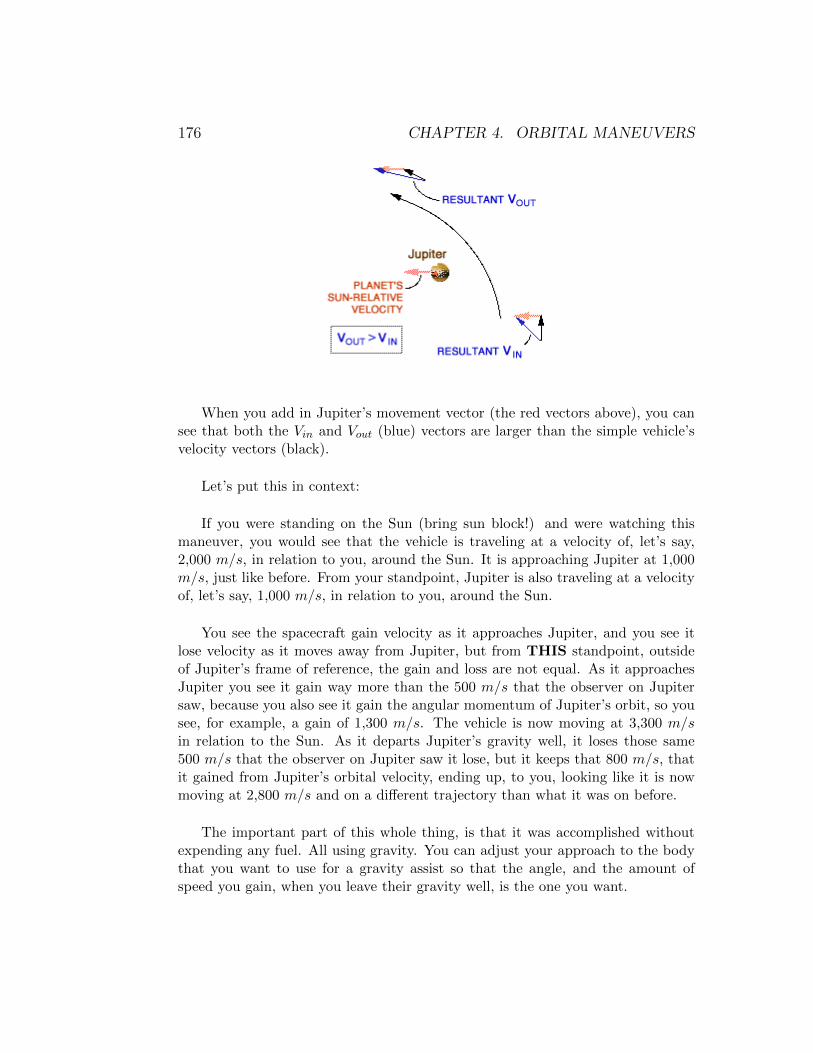
176 CHAPTER 4. ORBITAL MANEUVERS
When you add in Jupiter’s movement vector (the red vectors above), you cansee that both the Vin and Vout (blue) vectors are larger than the simple vehicle’svelocity vectors (black).
Let’s put this in context:
If you were standing on the Sun (bring sun block!) and were watching thismaneuver, you would see that the vehicle is traveling at a velocity of, let’s say,2,000 m/s, in relation to you, around the Sun. It is approaching Jupiter at 1,000m/s, just like before. From your standpoint, Jupiter is also traveling at a velocityof, let’s say, 1,000 m/s, in relation to you, around the Sun.
You see the spacecraft gain velocity as it approaches Jupiter, and you see itlose velocity as it moves away from Jupiter, but from THIS standpoint, outsideof Jupiter’s frame of reference, the gain and loss are not equal. As it approachesJupiter you see it gain way more than the 500 m/s that the observer on Jupitersaw, because you also see it gain the angular momentum of Jupiter’s orbit, so yousee, for example, a gain of 1,300 m/s. The vehicle is now moving at 3,300 m/sin relation to the Sun. As it departs Jupiter’s gravity well, it loses those same500 m/s that the observer on Jupiter saw it lose, but it keeps that 800 m/s, thatit gained from Jupiter’s orbital velocity, ending up, to you, looking like it is nowmoving at 2,800 m/s and on a different trajectory than what it was on before.
The important part of this whole thing, is that it was accomplished withoutexpending any fuel. All using gravity. You can adjust your approach to the bodythat you want to use for a gravity assist so that the angle, and the amount ofspeed you gain, when you leave their gravity well, is the one you want.
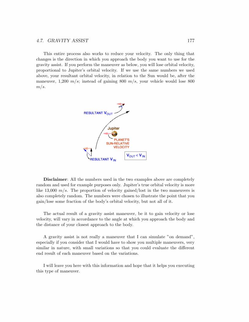
4.7. GRAVITY ASSIST 177
This entire process also works to reduce your velocity. The only thing thatchanges is the direction in which you approach the body you want to use for thegravity assist. If you perform the maneuver as below, you will lose orbital velocity,proportional to Jupiter’s orbital velocity. If we use the same numbers we usedabove, your resultant orbital velocity, in relation to the Sun would be, after themaneuver, 1,200 m/s; instead of gaining 800 m/s, your vehicle would lose 800m/s.
Disclaimer: All the numbers used in the two examples above are completelyrandom and used for example purposes only. Jupiter’s true orbital velocity is morelike 13,000 m/s. The proportion of velocity gained/lost in the two maneuvers isalso completely random. The numbers were chosen to illustrate the point that yougain/lose some fraction of the body’s orbital velocity, but not all of it.
The actual result of a gravity assist maneuver, be it to gain velocity or losevelocity, will vary in accordance to the angle at which you approach the body andthe distance of your closest approach to the body.
A gravity assist is not really a maneuver that I can simulate ”on demand”,especially if you consider that I would have to show you multiple maneuvers, verysimilar in nature, with small variations so that you could evaluate the differentend result of each maneuver based on the variations.
I will leave you here with this information and hope that it helps you executingthis type of maneuver.

178 CHAPTER 4. ORBITAL MANEUVERS
4.8 Landing
Landing sounds like a fairly simple maneuver, however it is one of the more complexmaneuvers that you will execute in the game.
The reason it is difficult is that for you to land successfully (without explod-ing or otherwise destroying your vehicle), you must do so at a very low velocity,typically less than about 5 m/s. The problem is that for you to maintain properattitude when you are moving this slowly and being pulled by gravity, all at thesame time, is very difficult because your ship is very unstable. Using SAS tocontrol your attitude at this phase of the maneuver is HIGHLY recommended.
Another point that sometimes people overlook, is that for you to land suc-cessfully, your velocity, in relation to the surface that your are trying to land on,should be as close to 0.0 m/s as possible. However in game, there is no indicator ofyour horizontal velocity. You have to gauge, based on the vertical speed indicator(next to the altimeter), and the speed indicator (above the navball) and kind ofdeduce what your horizontal velocity might be. Usually it’s easier just to view theterrain and see if you are moving in relation to it.
Disclaimer: I don’t claim that this is the best or most efficient way to performa landing. I’m sure there are people that can do this WAY better than I can, butthis WORKS (not that any other method doesn’t). If you like my method, enjoy,if you don’t like my method, write a thorough description on how to perform thisbetter and I will be happy to include it in the next edition of this book.
But let’s try to do this. Our starting point is a circular, equatorial orbit at30,000 meters, around the Mun. Our intention is to land somewhere north of thebig crater that sits right below the equator of the Mun.
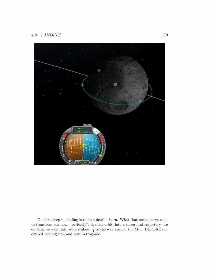
4.8. LANDING 179
Our first step in landing is to do a deorbit burn. What that means is we wantto transform our now, ”perfectly”, circular orbit, into a suborbital trajectory. Todo this, we wait until we are about 1
4 of the way around the Mun, BEFORE ourdesired landing site, and burn retrograde.

180 CHAPTER 4. ORBITAL MANEUVERS
We want to burn retrograde enough so that our blue trajectory line ends upslightly AFTER where we want to land. The reason for this is that the bluetrajectory line is a perfect parabola and we don’t want to perform a paraboliclanding maneuver (they are possible, but extremely difficult). What we want todo is make our trajectory ”overshoot” our target landing site by a little bit, thismeans we will still be ”in the air” as we pass over our desired landing site.

4.8. LANDING 181
It is at this point that we want to burn retrograde again to lower our velocityto virtually 0.0 m/s. This will allow us to descend straight to our desired landingsite.
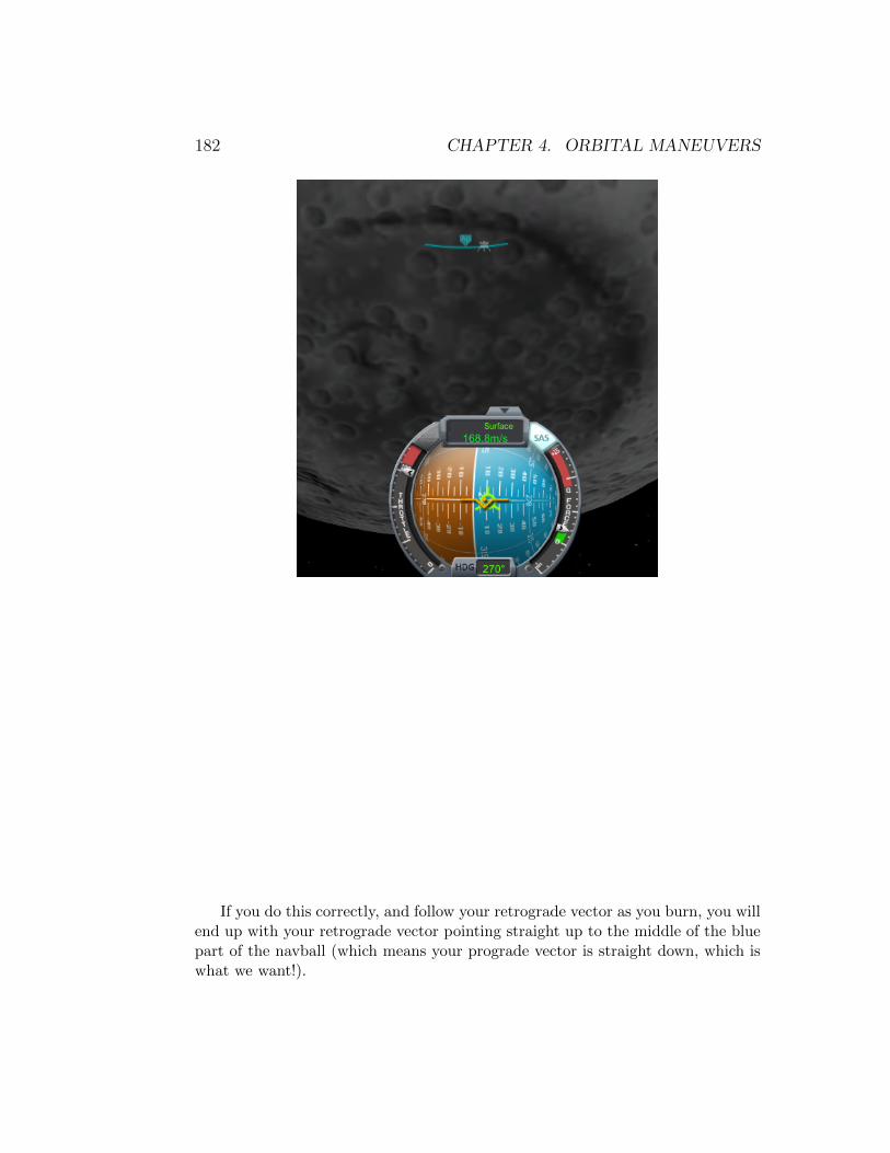
182 CHAPTER 4. ORBITAL MANEUVERS
If you do this correctly, and follow your retrograde vector as you burn, you willend up with your retrograde vector pointing straight up to the middle of the bluepart of the navball (which means your prograde vector is straight down, which iswhat we want!).

4.8. LANDING 183
When we turn off our engines at this point, we will start to gain velocity again.This is the Mun’s gravity pulling us down. This is where things get complicated.We don’t know how high up we are because the altimeter on the main flight screenis showing altitude to sea level. The actual surface of the Mun is going to showup WAY before that reaches anything close to 0. The only way, without mods, toknow your true altitude in relation to the surface is to check the radar altimeterin the cockpit. Press c .
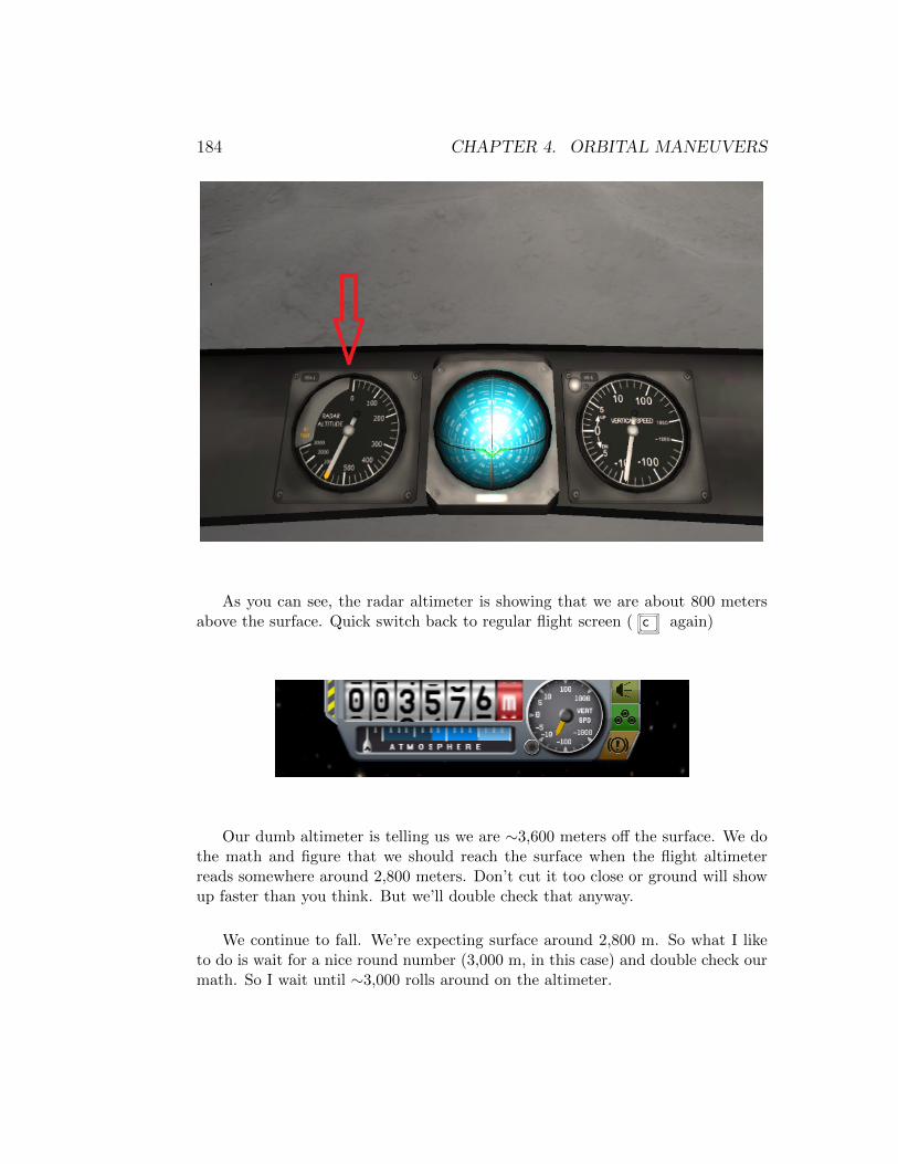
184 CHAPTER 4. ORBITAL MANEUVERS
As you can see, the radar altimeter is showing that we are about 800 metersabove the surface. Quick switch back to regular flight screen ( c again)
Our dumb altimeter is telling us we are ∼3,600 meters off the surface. We dothe math and figure that we should reach the surface when the flight altimeterreads somewhere around 2,800 meters. Don’t cut it too close or ground will showup faster than you think. But we’ll double check that anyway.
We continue to fall. We’re expecting surface around 2,800 m. So what I liketo do is wait for a nice round number (3,000 m, in this case) and double check ourmath. So I wait until ∼3,000 rolls around on the altimeter.

4.8. LANDING 185
Once I’m there, I press c to switch back to the cockpit. If our math is right,our radar altimeter in the cockpit should be showing about 200 meters
Bingo! It looks like it’s a little below 200 meters, so let’s readjust our estimateof surface from 2,800 meters to 2,850 meters just to be on the safe side.
Time to slow down big time
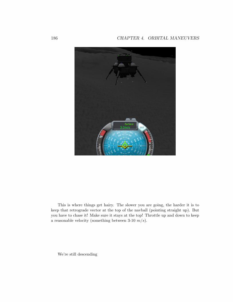
186 CHAPTER 4. ORBITAL MANEUVERS
This is where things get hairy. The slower you are going, the harder it is tokeep that retrograde vector at the top of the navball (pointing straight up). Butyou have to chase it! Make sure it stays at the top! Throttle up and down to keepa reasonable velocity (something between 3-10 m/s).
We’re still descending

4.8. LANDING 187
We’re at 2,919 meters. Our radar altimeter should be marking around 75-100meters if our math is right. Let’s see.
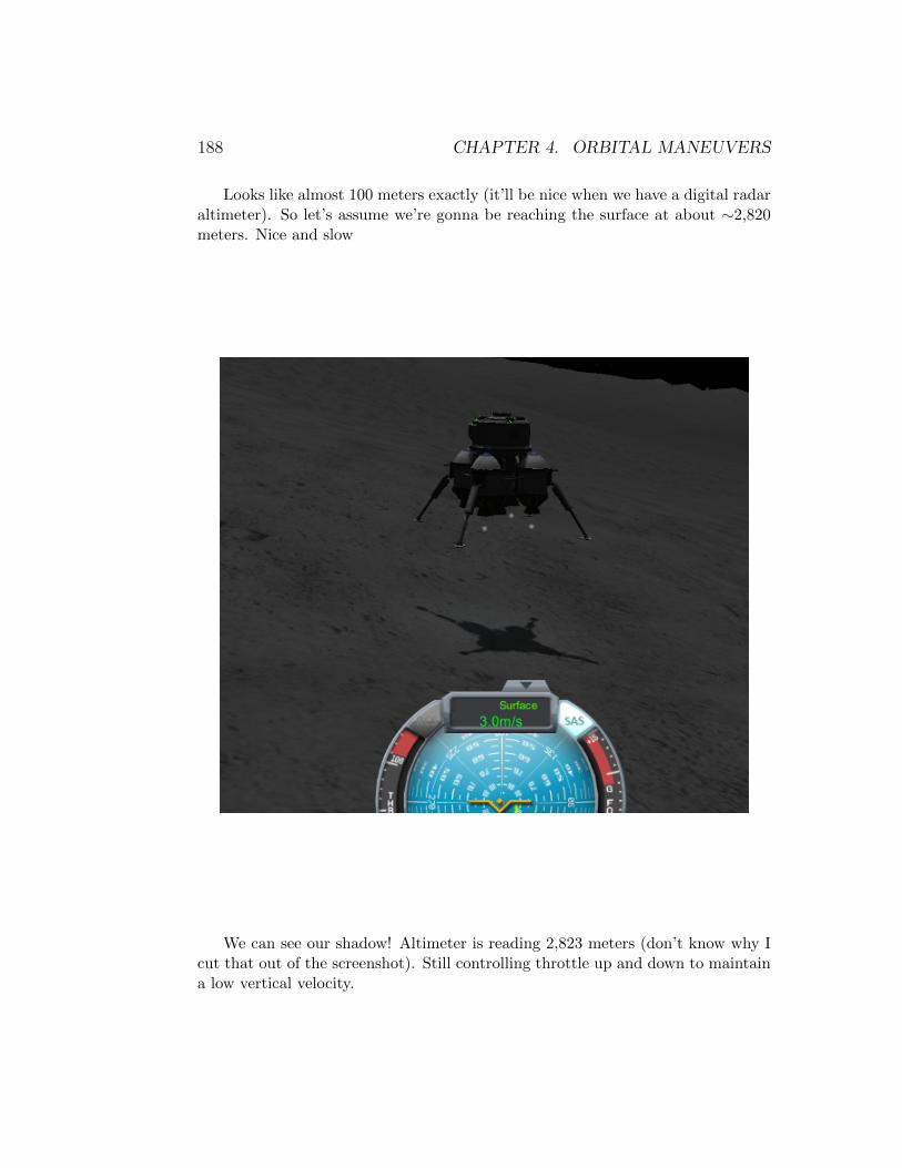
188 CHAPTER 4. ORBITAL MANEUVERS
Looks like almost 100 meters exactly (it’ll be nice when we have a digital radaraltimeter). So let’s assume we’re gonna be reaching the surface at about ∼2,820meters. Nice and slow
We can see our shadow! Altimeter is reading 2,823 meters (don’t know why Icut that out of the screenshot). Still controlling throttle up and down to maintaina low vertical velocity.
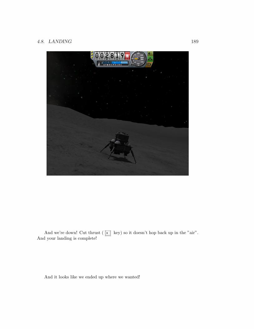
4.8. LANDING 189
And we’re down! Cut thrust ( x key) so it doesn’t hop back up in the ”air”.And your landing is complete!
And it looks like we ended up where we wanted!
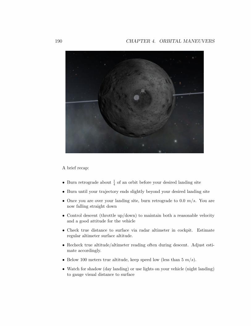
190 CHAPTER 4. ORBITAL MANEUVERS
A brief recap:
• Burn retrograde about 14 of an orbit before your desired landing site
• Burn until your trajectory ends slightly beyond your desired landing site
• Once you are over your landing site, burn retrograde to 0.0 m/s. You arenow falling straight down
• Control descent (throttle up/down) to maintain both a reasonable velocityand a good attitude for the vehicle
• Check true distance to surface via radar altimeter in cockpit. Estimateregular altimeter surface altitude.
• Recheck true altitude/altimeter reading often during descent. Adjust esti-mate accordingly.
• Below 100 meters true altitude, keep speed low (less than 5 m/s).
• Watch for shadow (day landing) or use lights on your vehicle (night landing)to gauge visual distance to surface
4.8. LANDING 191
• Try to land with less than 5 m/s of velocity (less than 3 m/s is even better)
• Cut engines immediately upon touchdown
• Call Mission Control and say ”The Eagle has landed!” or some other mem-orable phrase.
Suicide Burn
or How I learned to live dangerously!
A suicide burn is a very aptly named maneuver because in many instances itwill result in pieces of ships and/or kerbals strewn across the landscape.
My above landing procedure, while ”easy”, is not even close to an efficientlanding. I used more than half of the fuel in the two stage lander to accomplishthat landing.
The most efficient way to land is to wait until the last possible moment, andburn retrograde at full thrust in such a fashion that as you reach the ground,you velocity is exactly 0.0 m/s (or low enough that things don’t fall apart upontouchdown).
I have two problems with suicide burns:
1. I don’t know, with any degree of certainty, my exact altitude above thesurface. This information is crucial to know exactly when to start a suicideburn (remember, you start it at the last possible moment)
2. I don’t know, with any degree of certainty, how fast my vehicle can decel-erate. This can be mitigated if I’ve flown the same vehicle various timesand know how it ”responds”. But remember that the vehicle will performdifferently depending on it’s mass. If I have full tanks, it will be sluggish, ifI’ve already burned off have my fuel, it will be more responsive.

192 CHAPTER 4. ORBITAL MANEUVERS
So, a suicide burn to me sounds like, well. . . just plain suicide (I guess theburn part comes in when the explosion happens).
But we can work with this. . . instead of being super cautious (like I was above)and decelerating to ∼10 m/s at 200 meters of altitude, you can ”semi-suicide” andlet it ride until about 100 or even 50 meters, then burn full thrust to cancel allthat vertical velocity, and just be cautious those last 25-50 meters. It’s really upto you.
A suicide burn is nothing more than a launch in reverse and is truly the mostefficient (fuel-wise) method of performing a landing. I think an unassisted (i.e.manual) suicide burn is just crazy. No one in real life would even attempt to per-form such a maneuver without the assistance of a computer (MechJeb, anyone?),but to each his own. It would be like giving the astronauts on the shuttle manualcontrol of engine gimbals to maintain the attitude of the craft during launch (yeah,that would end well!).
I hope this information will help you on your way to planting flags on variouscelestial bodies in the Kerbol system!

Thank You!
Thank you for reading this book! It was a joy to write and I anticipate the othervolumes will be the same.
Stay tuned for news on the next volume!
193