KEOR COMPACT 3 111 06 DRY CONTACT CARD Installation Manual
16
NO NC OUT-3 J4 NO NC OUT-2 J2 NO NC OUT-1 J1 NO NC OUT-4 J5 NO NC OUT-5 J7 NO NC OUT-6 J8 1st 2nd J9 J3 1st 2nd J6 LE12723AA – 20/12 The copying, redistribution, use or publication of such contents is strictly prohibited without Legrand authorization KEOR COMPACT 3 111 06 DRY CONTACT CARD Installation Manual
Transcript of KEOR COMPACT 3 111 06 DRY CONTACT CARD Installation Manual

NO NCOUT-3J4
NO NCOUT-2J2
NO NCOUT-1J1
NO NC OUT-4J5
NO NC OUT-5J7
NO NC OUT-6J8
1st 2ndJ9
J3
1st
2
nd
J6
LE12723AA – 20/12
The copying, redistribution, use or publication of such contents is strictly prohibited without Legrand authorization
KEOR COMPACT 3 111 06 DRY CONTACT CARD
Installation Manual

KEOR COMPACT DRY CONTACT CARD
2
Table of Contents
1. Introduction .................................................................................................. 3
1.1 Guarantee terms ................................................................................. 3
2. Safety provisions .......................................................................................... 4
3. Installation Procedure ................................................................................... 5
3.1 Component List ................................................................................... 5
3.2 Electrical Specification ........................................................................ 5
3.3 Dry Contact Card Hardware Setting .................................................... 5
3.4 Pin Assignment of Output/Input Contacts ............................................ 7
3.5 Hardware Installation Procedure ......................................................... 8
3.6 Communication Setting Procedure ...................................................... 8
3.7 Configure Output/Input Contacts ....................................................... 10

KEOR COMPACT DRY CONTACT CARD
3
1. Introduction The main purpose of this dry contact card is to send the information about the abnormal events happen in UPS to the other apparatus so that this equipment can understand the current situation and
act accordingly. This card provides six output relays and six input contacts. The UPS can install up to 2 dry contact cards. All output and input contacts are programmable, and user can define the definition for each contact using setting tool.
The prevalent requirements of output information include: Mains input fault alarm, Bypass fault alarm, Battery weak alarm, Output overload alarm so on and so forth. The prevalent requirement of input information includes: Single shutdown, System shutdown, Single
start, System start, Transfer to bypass in single operation, Transfer to bypass in parallel operation, EPO (Emergency shutdown).
The purpose of this manual is to provide indications for installing and using safely the LEGRAND dry contact card 3 109 69. It is essential that this manual is read through, but it is not a substitute for the expertise of the technical
personnel who must have had adequate preliminary training. The dry contact card has been built for the applications specified in this manual. For no reason whatsoever it is allowed a use for purposes other than those for which it has been designed, nor in
ways different to those explained in the manual. This manual must be kept in a safe, dry place and always be available for consultation. We suggest
making a copy and filing it. The manual is to be considered an integral part of the dry contact card and therefore must be kept for the card’s useful life cycle.
The original text of this publication is in English and is the only reference for solving any interpretation disputes related to the translation into other languages.
The information in this manual must not be disclosed to third parties. Any duplication, total or partial, not authorized in writing by the Manufacturer violates the copyright conditions and can be prosecuted by law.
LEGRAND reserves the property rights of this publication and forbids the total or partial reproduction of it without prior written consent.
1.1 Guarantee terms
The guarantee conditions may vary depending on the country where the dry contact card is sold. Check with your local LEGRAND sale representative for validity and duration. In order to use the guarantee supplied by the Manufacturer the user must scrupulously comply with the
precautions indicated in the manual .
The Manufacturer declines all liabilities, direct and indirect, resulting from:
- disregard for the instructions by the specialized technician and a use of the card different
from the one stated in the manual;
- use by personnel who have not read and understood properly the contents of the manual;
- a use failing to conform to the specific laws existing in the country of installation;
- changes made to the equipment, operating logic or tampering;
- repairs unauthorized by the Technical Service Assistance of LEGRAND;
- damages caused by willful misconduct, gross negligence, exceptional events, fire or
infiltration of liquids.

KEOR COMPACT DRY CONTACT CARD
4
2. Safety provisions
ATTENTION It is necessary to read these safety provisions before doing any operation.
DANGER
This product should be installed in compliance with installation rules, preferably by a qualified electrician. Incorrect installation and use can lead to risk of electric shock or fire. Before carrying out the installation, read the instructions and take account of the product’s specific
mounting location. Do not open up, dismantle, alter or modify the device except where specifically required to do so by the instructions. All Legrand products must be opened and repaired exclusively by personnel trained and
approved by Legrand. Any unauthorized opening or repair completely cancels all liabilities and the rights to replacement and guarantees. Use only Legrand brand accessories.
DANGER The dry contact card must be installed only with the UPS UNPLUGGED FROM THE MAINS.
ATTENTION The dry contact card 3 110 99 can only be used in the expansion slot of the UPS KEOR COMPACT manufactured by LEGRAND.
ATTENTION It is required to connect the dry contacts of the card by strictly following the instructions provided in this
manual. The UPS and the card may be damaged if the installation and operating procedures are not followed.
ATTENTION Inspect the dry contact card immediately after opening the packaging. If it appears damaged, do not install it inside the UPS but immediately contact the Technical Service Assistance of LEGRAND. In case of problems with the card, you should read this manual before contacting the Technical Service
Assistance of LEGRAND. If the problem persists, contact the Technical Service Assistance of LEGRAND that will provide all the instructions on how to proceed.
KEOR COMPACT DRY CONTACT CARD
5
3. Installation Procedure
3.1 Component List The dry contact card package includes below items:
• Dry-contact card × 1
• M3 Screw × 2
3.2 Electrical Specification
• Output Relay:250VAC / 2A, 30VDC / 2A
• Input Contact:When the contact is closed, a current of 10mA max circulates.
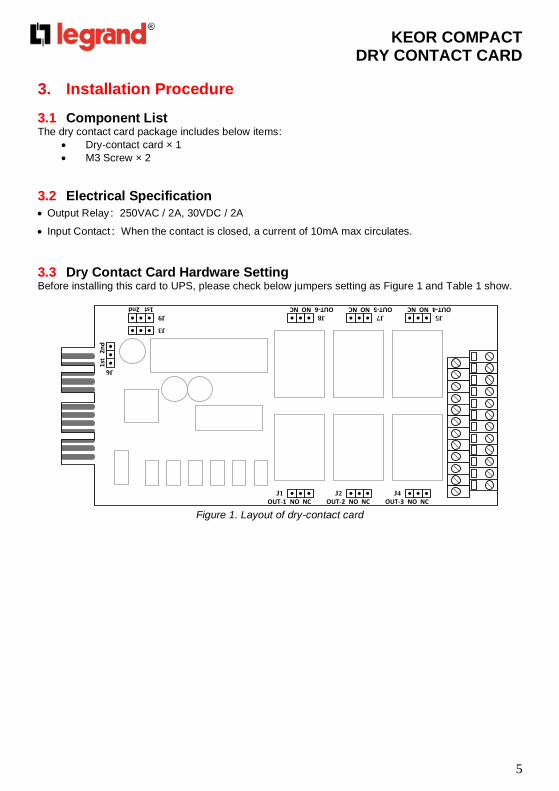
3.3 Dry Contact Card Hardware Setting Before installing this card to UPS, please check below jumpers setting as Figure 1 and Table 1 show.
NO NCOUT-3J4
NO NCOUT-2J2
NO NCOUT-1J1
NO NC OUT-4J5
NO NC OUT-5J7
NO NC OUT-6J8
1st 2ndJ9
J3
1st
2
nd
J6
Figure 1. Layout of dry-contact card

KEOR COMPACT DRY CONTACT CARD
6
Table 1
Jumper Function Descriptions Setting
J3
J6
J9
These three jumpers to select the
communication slot of UPS which one
this dry-contact card will be installed.
Slot 1: 1st 2nd
Slot 2: 1st 2nd※
J1 Out Relay#1 NO/NC setting
NO (Normal Open)
NO NC
J2 Out Relay#2 NO/NC setting
J4 Out Relay#3 NO/NC setting
J5 Out Relay#4 NO/NC setting NC (Normal Closed)
NO NC
J7 Out Relay#5 NO/NC setting
J8 Out Relay#6 NO/NC setting
※ Check the TACI4xx PCB board SW2 is on the Slot sides Figure 2 shows
Figure 2. TACI4XX PCB board SW2
If you insert Dry Contact Card into the Slot2,you must select Slot side on the SW2.

KEOR COMPACT DRY CONTACT CARD
7
3.4 Pin Assignment of Output/Input Contacts This card provides six output relays and six input contacts. The pin assignment as Figure 3 shows.
OUT
IN
IN-1 IN-2 IN-3 IN-4 IN-5 IN-6
OUT-1 OUT-2 OUT-3 OUT-4 OUT-5 OUT-6
OUT-1 Output Relay 1
OUT-2 Output Relay 2
OUT-3 Output Relay 3
OUT-4 Output Relay 4
OUT-5 Output Relay 5
OUT-6 Output Relay 6
IN-1 Input Contact 1
IN-2 Input Contact 2
IN-3 Input Contact 3
IN-4 Input Contact 4
IN-5 Input Contact 5
IN-6 Input Contact 6
Figure 3

KEOR COMPACT DRY CONTACT CARD
8
3.5 Hardware Installation Procedure Please refer to section 1.3 to set all jumpers of the dry contact card before install to UPS.
Plug in the dry contact card to the《Slot1》or《Slot2》and then screw in the screws after the card is
firmly locked in to complete the installation procedure, as Figure 4 shows.
Figure 4
3.6 Communication Setting Procedure
• Please configure the setting of this card via the LCD control panel and the setup procedure as shows in Figure 5.
• The programmable parameters as shows in table below.
Item Setting
ID 1
Stop Bit 1
Parity Check None
Baud Rate 57600
• In parallel system, please click to select the machine ID which installs the dry contact card before you change the setting.

KEOR COMPACT DRY CONTACT CARD
9
Figure 5
• Please use the setting tool software to confirm the configuration of the dry contact card.
• Go to 『Information』->『Status』->『Dry Contact』 page to identify whether the dry
contact card is properly set. If the card is installed correctly, “Yes” will be appeared.

KEOR COMPACT DRY CONTACT CARD
10
3.7 Configure Output/Input Contacts • Please use the setting tool software to configure the output/Input contacts.
• Go to 『Setting』 ->『Configurations Value』 ->『Dry Contact』 page to change the
definition for each contact.
• Configure Output Relay ➢ The status and alarm events can be set. ➢ The status code list show as Table 2. ➢ The alarm code list show as Table 3.
➢ Example 1:Set Status S23 “Load on Bypass” to slot1 output relay1. Please keyin
setting value “1023”.
➢ Example 2:Set alarm A10 “Over Temperature” to slot2 output relay3. Please
keyin setting value “10”.
• Configure Input Contact ➢ The available command code list show as Table 4.

KEOR COMPACT DRY CONTACT CARD
11
➢ Example:Set command C05 “Shutdown” to slot1 input contact 2. Please keyin
setting value “5”.

KEOR COMPACT DRY CONTACT CARD
12
Table 2. Status Code List
Code Description Setting Value
S00 Rectifier Input Present OK 1000
S01 Bypass Input Present OK 1001
S05 UPS in Normal Mode 1005
S07 UPS in ECO Mode 1007
S08 UPS in Converter Mode 1008
S14 Rectifier on 1014
S15 Inverter on 1015
S16 Battery Discharger on 1016
S17 Battery Charger on 1017
S21 Load off 1021
S22 Load on Inverter 1022
S23 Load on Bypass 1023
S24 Load on Manual bypass 1024
S33 Unitary Operation 1033
S34 Parallel Operation 1034
S35 Redundancy Operation 1035
S40 Vbatt. Ok 1040
S41 Vbatt. Low 1041
S42 Vbatt. Min 1042
S48 Battery Charging Compensation 1048
S50 Battery Precharge Kit Available 1050
S51 Permission for Close Battery Switch 1051
S52 Cold Start Ready 1052
S61 Buzzer Enable 1061
S63 Automatic Restart Enable 1063
S67 Manual Bypass Switch Closed 1067
S69 Output Switch Closed 1069
S71 Bypass SCR Activated 1071
S72 Battery Switch Closed 1072
S77 Output Contactor Closed 1077
S84 Unit is Master 1084
S85 Unit is Slave 1085
S106 System Load off 1106
S107 System Load on Inverter 1107
S108 System Load on Bypass 1108

KEOR COMPACT DRY CONTACT CARD
13
Table 3. Alarm Code List
Code Description Setting Value
A01 General Alarm 01
A02 Inverter General Alarm 02
A03 Mains General Alarm 03
A04 Discharger General Alarm 04
A05 Charger General Alarm 05
A06 Bypass General Alarm 06
A10 Over Temp. 10
A14 Interior over Temp. 14
A15 Battery Room over Temp. 15
A16 Converter Stop Due To UPS Overheat 16
A25 Inverter Fault 25
A26 Rectifier Fault 26
A27 Discharger Fault 27
A28 Charger Fault 28
A29 Bypass SCR Fault 29
A30 Fan out of Order 30
A31 Temp. Sensor Disconnected 31
A46 Mains Input out of Tolerance 46
A47 Mains Input Disconnected or Fuse Open 47
A48 Mains Input Phase Rotation Error 48
A49 Mains Input 3 Phase Current Unbalance 49
A50 Mains Input Voltage Low 50
A58 Inverter Output Voltage out of Tolerance 58
A59 Output contactor broken or output fuse open 59
A60 Inverter Output DC Offset too High 60
A61 Output Short Circuit 61
A69 Bypass Short Circuit 69
A70 Bypass Preventive Alarm 70
A71 Bypass Critical Alarm 71
A72 Bypass Phase Rotation Error 72
A73 Bypass Phase Error 73
A74 Backfeed Protection Active 74
A76 Lock on Bypass 76
A78 Bypass out of THD Tolerance 78
A82 Battery Disconnected or Fuse Open 82
A83 Vbatt. Min 83
A84 Vbatt. Low 84
A85 Battery over Voltage 85
A86 Charger over Current 86
A90 Inverter Overload 90
A91 Bypass Overload 91
A92 UPS Overload Shutdown 92
A94 System Occurred Unpredictable Interrupt Output 94
A95 Rectifier Rating down to 50% 95
A96 Transfer Impossible 96
A97 Output Switch Open 97
A100 Manual Bypass Aalarm 100
A101 Battery Near End of Life 101

KEOR COMPACT DRY CONTACT CARD
14
A102 UPS Maintenance Alarm 102
A129 Sync. of Start or Load Transfer Error 129
A132 EPO(emergency power off) active 132
A133 External Alarm 1 Active 133
A134 External Alarm 2 Active 134
A135 External Alarm 3 Active 135
A136 External Alarm 4 Active 136
A137 External Alarm 5 Active 137
A138 External Alarm 6 Active 138
A139 External Alarm 7 Active 139
A140 External Alarm 8 Active 140
A141 External Alarm 9 Active 141
A142 External Alarm 10 Active 142
A143 External Alarm 11 Active 143
A144 External Alarm 12 Active 144
Table 4. Command Code List
Code Description Setting Value
C00 Normal Mode 0
C02 ECO Mode 2
C03 Converter Mode 3
C05 Shutdown 5
C06 Load on Bypass 6
C11 Buzzer Disable 11
C12 Buzzer Enable 12
C14 Clear Latch Alarm and Buzzer 14
C200 System Normal Mode on 200
C202 System ECO Mode on 202
C203 System CVCF Mode on 203
C205 System Shutdown 205
C206 System Shut down Converter Except Bypass 206
C256 External Alarm 1 Active 256
C257 External Alarm 2 Active 257
C258 External Alarm 3 Active 258
C259 External Alarm 4 Active 259
C260 External Alarm 5 Active 260
C261 External Alarm 6 Active 261
C262 External Alarm 7 Active 262
C263 External Alarm 8 Active 263
C264 External Alarm 9 Active 264
C265 External Alarm 10 Active 265
C266 External Alarm 11 Active 266
C267 External Alarm 12 Active 267

KEOR COMPACT DRY CONTACT CARD
15

KEOR COMPACT DRY CONTACT CARD
16