KempArc SYN 300, 400, 500 · KempArc SYN is a product family for welding automation that includes...
26
Operating manual • English Käyttöohje • Suomi Bruksanvisning • Svenska Bruksanvisning • Norsk Brugsanvisning • Dansk Gebrauchsanweisung • Deutsch Gebruiksaanwijzing • Nederlands Manuel d’utilisation • Français Manual de instrucciones • Español Instrukcja obsługi • Polski Инструкции по эксплуатации • По-русски Manual de utilização • Português EN FI SV NO DA DE NL FR ES PL RU PT KempArc SYN 300, 400, 500 DT 400
Transcript of KempArc SYN 300, 400, 500 · KempArc SYN is a product family for welding automation that includes...

Operating manual • English
Käyttöohje • Suomi
Bruksanvisning • Svenska
Bruksanvisning • Norsk
Brugsanvisning • Dansk
Gebrauchsanweisung • Deutsch
Gebruiksaanwijzing • Nederlands
Manuel d’utilisation • Français
Manual de instrucciones • Español
Instrukcja obsługi • Polski
Инструкции по эксплуатации • По-русски
Manual de utilização • Português
EN
FI
SV
NO
DA
DE
NL
FR
ES
PL
RU
PT
KempArc SYN 300, 400, 500DT 400


OPERATING MANUALEnglish
Kem
pArc
SYN
300
, 400
, 500
, DT
400
/ © K
empp
i Oy
/ 111
7
EN
CONTENTS
1. PREFACE . . . . . . . . . . . . . . . . . . . . . . . . . . . . . . . . . . . . . . . . . . . . . . . . . . . . . . . . . . . . . . . . . . . . . . . . . . . . . . . . . . . . . . . . . . . . . . . . . . . . . . . . . . . . . . . . . . . . . . . . . . . . . . . . 31.1 General . . . . . . . . . . . . . . . . . . . . . . . . . . . . . . . . . . . . . . . . . . . . . . . . . . . . . . . . . . . . . . . . . . . . . . . . . . . . . . . . . . . . . . . . . . . . . . . . . . . . . . . . . . . . . . . . . . . . . . . . . . . . . . . . . . . . . . . 31.2 Introduction . . . . . . . . . . . . . . . . . . . . . . . . . . . . . . . . . . . . . . . . . . . . . . . . . . . . . . . . . . . . . . . . . . . . . . . . . . . . . . . . . . . . . . . . . . . . . . . . . . . . . . . . . . . . . . . . . . . . . . . . . . . . . 3
2. USE . . . . . . . . . . . . . . . . . . . . . . . . . . . . . . . . . . . . . . . . . . . . . . . . . . . . . . . . . . . . . . . . . . . . . . . . . . . . . . . . . . . . . . . . . . . . . . . . . . . . . . . . . . . . . . . . . . . . . . . . . . . . . . . . . . . . . . . . . . . . . 42.1 Power source . . . . . . . . . . . . . . . . . . . . . . . . . . . . . . . . . . . . . . . . . . . . . . . . . . . . . . . . . . . . . . . . . . . . . . . . . . . . . . . . . . . . . . . . . . . . . . . . . . . . . . . . . . . . . . . . . . . . . . . . . . . . 4
2.1.1 Power source components . . . . . . . . . . . . . . . . . . . . . . . . . . . . . . . . . . . . . . . . . . . . . . . . . . . . . . . . . . . . . . . . . . . . . . . . . . . . . . . . . . . . . . . . . . . . . 42.1.2 Positioning of the machine . . . . . . . . . . . . . . . . . . . . . . . . . . . . . . . . . . . . . . . . . . . . . . . . . . . . . . . . . . . . . . . . . . . . . . . . . . . . . . . . . . . . . . . . . . . . . 42.1.3 Distribution network . . . . . . . . . . . . . . . . . . . . . . . . . . . . . . . . . . . . . . . . . . . . . . . . . . . . . . . . . . . . . . . . . . . . . . . . . . . . . . . . . . . . . . . . . . . . . . . . . . . . . . . 52.1.4 Connecting the power source to the electric network . . . . . . . . . . . . . . . . . . . . . . . . . . . . . . . . . . . . . . . . . . . . . . . . . 52.1.5 Connecting the cables . . . . . . . . . . . . . . . . . . . . . . . . . . . . . . . . . . . . . . . . . . . . . . . . . . . . . . . . . . . . . . . . . . . . . . . . . . . . . . . . . . . . . . . . . . . . . . . . . . . . 62.1.6 Installing the field bus card . . . . . . . . . . . . . . . . . . . . . . . . . . . . . . . . . . . . . . . . . . . . . . . . . . . . . . . . . . . . . . . . . . . . . . . . . . . . . . . . . . . . . . . . . . . . . 72.1.7 Starting the power source . . . . . . . . . . . . . . . . . . . . . . . . . . . . . . . . . . . . . . . . . . . . . . . . . . . . . . . . . . . . . . . . . . . . . . . . . . . . . . . . . . . . . . . . . . . . . . 82.1.8 Power source indicators . . . . . . . . . . . . . . . . . . . . . . . . . . . . . . . . . . . . . . . . . . . . . . . . . . . . . . . . . . . . . . . . . . . . . . . . . . . . . . . . . . . . . . . . . . . . . . . . . . 8
2.2 Control panel . . . . . . . . . . . . . . . . . . . . . . . . . . . . . . . . . . . . . . . . . . . . . . . . . . . . . . . . . . . . . . . . . . . . . . . . . . . . . . . . . . . . . . . . . . . . . . . . . . . . . . . . . . . . . . . . . . . . . . . . . . . 82.2.1 Control panel parts . . . . . . . . . . . . . . . . . . . . . . . . . . . . . . . . . . . . . . . . . . . . . . . . . . . . . . . . . . . . . . . . . . . . . . . . . . . . . . . . . . . . . . . . . . . . . . . . . . . . . . . . . . 82.2.2 Adjusting MIG dynamics (Arc Force) . . . . . . . . . . . . . . . . . . . . . . . . . . . . . . . . . . . . . . . . . . . . . . . . . . . . . . . . . . . . . . . . . . . . . . . . . . . . . . 92.2.3 Gas test . . . . . . . . . . . . . . . . . . . . . . . . . . . . . . . . . . . . . . . . . . . . . . . . . . . . . . . . . . . . . . . . . . . . . . . . . . . . . . . . . . . . . . . . . . . . . . . . . . . . . . . . . . . . . . . . . . . . . . . . . . . . . 92.2.4 Wire feed test . . . . . . . . . . . . . . . . . . . . . . . . . . . . . . . . . . . . . . . . . . . . . . . . . . . . . . . . . . . . . . . . . . . . . . . . . . . . . . . . . . . . . . . . . . . . . . . . . . . . . . . . . . . . . . . . . . . 92.2.5 Selection of liquid- or gas-cooled MIG gun . . . . . . . . . . . . . . . . . . . . . . . . . . . . . . . . . . . . . . . . . . . . . . . . . . . . . . . . . . . . . . . . . . . 92.2.6 Retrieving weld data . . . . . . . . . . . . . . . . . . . . . . . . . . . . . . . . . . . . . . . . . . . . . . . . . . . . . . . . . . . . . . . . . . . . . . . . . . . . . . . . . . . . . . . . . . . . . . . . . . . . . 102.2.7 Selecting the welding process . . . . . . . . . . . . . . . . . . . . . . . . . . . . . . . . . . . . . . . . . . . . . . . . . . . . . . . . . . . . . . . . . . . . . . . . . . . . . . . . . . . . . . 102.2.8 Additional MIG features included in the standard delivery . . . . . . . . . . . . . . . . . . . . . . . . . . . . . . . . . . . . . . . . 102.2.9 Optional additional MIG features . . . . . . . . . . . . . . . . . . . . . . . . . . . . . . . . . . . . . . . . . . . . . . . . . . . . . . . . . . . . . . . . . . . . . . . . . . . . . . . . . 122.2.10 Memory features (MEMORY button) . . . . . . . . . . . . . . . . . . . . . . . . . . . . . . . . . . . . . . . . . . . . . . . . . . . . . . . . . . . . . . . . . . . . . . . . . . . . 122.2.11 Synergetic 1-MIG welding and WiseThin welding . . . . . . . . . . . . . . . . . . . . . . . . . . . . . . . . . . . . . . . . . . . . . . . . . . . . . . . 132.2.12 SETUP features of the control panel . . . . . . . . . . . . . . . . . . . . . . . . . . . . . . . . . . . . . . . . . . . . . . . . . . . . . . . . . . . . . . . . . . . . . . . . . . . . . 15
2.3 Wire feeder . . . . . . . . . . . . . . . . . . . . . . . . . . . . . . . . . . . . . . . . . . . . . . . . . . . . . . . . . . . . . . . . . . . . . . . . . . . . . . . . . . . . . . . . . . . . . . . . . . . . . . . . . . . . . . . . . . . . . . . . . . . . . . 16
3. MAINTENANCE . . . . . . . . . . . . . . . . . . . . . . . . . . . . . . . . . . . . . . . . . . . . . . . . . . . . . . . . . . . . . . . . . . . . . . . . . . . . . . . . . . . . . . . . . . . . . . . . . . . . . . . . . . . . . . 183.1 Cables . . . . . . . . . . . . . . . . . . . . . . . . . . . . . . . . . . . . . . . . . . . . . . . . . . . . . . . . . . . . . . . . . . . . . . . . . . . . . . . . . . . . . . . . . . . . . . . . . . . . . . . . . . . . . . . . . . . . . . . . . . . . . . . . . . . . . . . . 183.2 Power source . . . . . . . . . . . . . . . . . . . . . . . . . . . . . . . . . . . . . . . . . . . . . . . . . . . . . . . . . . . . . . . . . . . . . . . . . . . . . . . . . . . . . . . . . . . . . . . . . . . . . . . . . . . . . . . . . . . . . . . . . . 18
3.2.1 DuraTorque™ 400, 4-wheel wire feeder mechanism . . . . . . . . . . . . . . . . . . . . . . . . . . . . . . . . . . . . . . . . . . . . . . . . . . . 193.3 Regular maintenance . . . . . . . . . . . . . . . . . . . . . . . . . . . . . . . . . . . . . . . . . . . . . . . . . . . . . . . . . . . . . . . . . . . . . . . . . . . . . . . . . . . . . . . . . . . . . . . . . . . . . . . . . . 193.4 Disposal of the machine . . . . . . . . . . . . . . . . . . . . . . . . . . . . . . . . . . . . . . . . . . . . . . . . . . . . . . . . . . . . . . . . . . . . . . . . . . . . . . . . . . . . . . . . . . . . . . . . . . . . 20
4. TROUBLESHOOTING . . . . . . . . . . . . . . . . . . . . . . . . . . . . . . . . . . . . . . . . . . . . . . . . . . . . . . . . . . . . . . . . . . . . . . . . . . . . . . . . . . . . . . . . . . . . . . . . 204.1 Overload (yellow indicator lit) . . . . . . . . . . . . . . . . . . . . . . . . . . . . . . . . . . . . . . . . . . . . . . . . . . . . . . . . . . . . . . . . . . . . . . . . . . . . . . . . . . . . . . . . . 204.2 Control cable connector fuse . . . . . . . . . . . . . . . . . . . . . . . . . . . . . . . . . . . . . . . . . . . . . . . . . . . . . . . . . . . . . . . . . . . . . . . . . . . . . . . . . . . . . . . . . . . 204.3 Electric network overvoltage or undervoltage . . . . . . . . . . . . . . . . . . . . . . . . . . . . . . . . . . . . . . . . . . . . . . . . . . . . . . . . . 204.4 Missing phase in the electric network . . . . . . . . . . . . . . . . . . . . . . . . . . . . . . . . . . . . . . . . . . . . . . . . . . . . . . . . . . . . . . . . . . . . . . . . . . 204.5 Error codes . . . . . . . . . . . . . . . . . . . . . . . . . . . . . . . . . . . . . . . . . . . . . . . . . . . . . . . . . . . . . . . . . . . . . . . . . . . . . . . . . . . . . . . . . . . . . . . . . . . . . . . . . . . . . . . . . . . . . . . . . . . . . . 20
5. ORDERING NUMBERS . . . . . . . . . . . . . . . . . . . . . . . . . . . . . . . . . . . . . . . . . . . . . . . . . . . . . . . . . . . . . . . . . . . . . . . . . . . . . . . . . . . . . . . . . . . . . 22
6. TECHNICAL DATA . . . . . . . . . . . . . . . . . . . . . . . . . . . . . . . . . . . . . . . . . . . . . . . . . . . . . . . . . . . . . . . . . . . . . . . . . . . . . . . . . . . . . . . . . . . . . . . . . . . . . . . . 22
2
Kem
pArc
SYN
300
, 400
, 500
, DT
400
/ © K
empp
i Oy
/ 111
7

EN
1. PREFACE
1.1 GENERALCongratulations on your choice of the Kemparc SYN-series welding system. Reliable and durable, Kemppi products are affordable to maintain, and they increase your work productivity. This user manual contains important information on the use, maintenance and safety of your Kemppi product. The technical specifications of the device can be found at the end of the manual. Please read the manual carefully before using the equipment for the first time. For your safety and that of your working environment, pay particular attention to the safety instructions in the manual.For more information on Kemppi products, contact Kemppi Oy, consult an authorised Kemppi dealer, or visit the Kemppi web site at www.kemppi.com.The specifications presented in this manual are subject to change without prior notice.
NOTE! Items in the manual that require particular attention in order to minimise damage and personal harm are indicated with this symbol. Read these sections carefully and follow their instructions.
DisclaimerWhile every effort has been made to ensure that the information contained in this guide is accurate and complete, no liability can be accepted for any errors or omissions. Kemppi reserves the right to change the specification of the product described at any time without prior notice. Do not copy, record, reproduce or transmit the contents of this guide without prior permission from Kemppi.
1.2 INTRODUCTIONKempArc SYN is a product family for welding automation that includes all welding devices needed in robot welding. The KempArc SYN welding system includes the following devices:
• KempArc SYN 300, SYN 400 and SYN 500 are synergetic welding power sources designed particularly for welding automation that are suitable for MIG welding with direct current. There are three power types of power sources: the 300, 400 and 500 ampere models. For more information on using power sources and their functions, see "Power source".
• RF 59 is a control panel that contains the programs and welding parameters needed in controlling the welding hardware. The panel functions allow the user to control the operation of the welding hardware and adjust its welding settings. The control panel is located in the front panel of the welding power source. For more information on using the control panel and its functions, see "Control panel".
• KempArc DT 400 is a wire feeding device that feeds welding wire to the welding robot at the speed it requires at any time. For more information on using the wire feeder and its functions, see "Wire feeder".
This guide presents the functions, operation and technical properties of the above devices. The devices also include the KempCool 10 cooler, but its functions and features are presented in a separate guide.The KempArc Synergic hardware is connected to the welding robot control system with the control unit on top of the power source.
3
Kem
pArc
SYN
300
, 400
, 500
, DT
400
/ © K
empp
i Oy
/ 111
7

EN
2. USE
2.1 POWER SOURCE
2.1.1 Power source components
A11
A1
A2
A4
A6
A12
A5
A7
A10
A8
A9A3
1 2 3 4
1 Robot Control2 Wire Feeder
3 Throughput4 Analog
A1 Control panelA2 Main switchA3 Signal light (I/O)A4 Thermal warning lightA5 Welding cable connection (parallel)A6 Earthing cable connectionA7 Control cable connection (parallel)A8 Cooling unitA9 Mains cableA10 Fuse for control cable connection (6.3 A slow)A11 Fan grillA12 Transportation handles
2.1.2 Positioning of the machinePlace the machine on a firm, dry and level surface. Where possible, do not allow dust or other impurities to enter the machines cooling air flow. Preferably site the machine above floor level; for example on a suitable carriage unit.Notes for positioning the machine
• The surface inclination should not exceed 15 degrees.• Ensure the free circulation of the cooling air. There must be at least 20 cm of free space in
front of and behind the machine for cooling air to circulate.• Protect the machine against heavy rain and direct sunshine.
NOTE! The machine should not be operated in the rain as the protection class of the machine, IP23S, allows for outside preserving and storage only.
NOTE! Never aim metallic grinding spray/sparks towards the equipment.
4
Kem
pArc
SYN
300
, 400
, 500
, DT
400
/ © K
empp
i Oy
/ 111
7
EN
2.1.3 Distribution networkAll regular electrical devices without special circuits generate harmonic currents into distribution network. High rates of harmonic current may cause losses and disturbance to some equipment.
KempArc 500This equipment complies with IEC 61000-3-12 provided that the short-circuit power Ssc is greater than or equal to 4.6 MVA at the interface point between the user’s supply and the public supply network. It is the responsibility of the installer or user of the equipment to ensure, by consultation with the distribution network operator if necessary, that the equipment is connected only to a supply with a short-circuit power Ssc greater than or equal to 4.6 MVA.
KempArc 400This equipment complies with IEC 61000-3-12 provided that the short-circuit power Ssc is greater than or equal to 4.7 MVA at the interface point between the user’s supply and the public supply network. It is the responsibility of the installer or user of the equipment to ensure, by consultation with the distribution network operator if necessary, that the equipment is connected only to a supply with a short-circuit power Ssc greater than or equal to 4.7 MVA.
KempArc 300:WARNING: This equipment does not comply with IEC 61000-3-12. If it is connected to a public low voltage system, it is the responsibility of the installer or user of the equipment to ensure, by consultation with the distribution network operator if necessary, that the equipment may be connected.
2.1.4 Connecting the power source to the electric networkThe KempArc SYN power source is connected to a 400-V three-phase network. The machine is equipped with a five-metre mains cable that does not have a plug. Before use, check the mains cable and install a mains plug. If the cable does not comply with the local electrical regulations, replace it with a compliant cable.
NOTE! The mains cable or plug may be installed or replaced by only an electrical contractor or installer authorised to perform such operations.
Replacement of the mains cable1. Unscrew the mounting screws on the top and sides of the machine, and remove the case
by lifting it.2. Disconnect the phase leads from connectors L1, L2, and L3, and disconnect the
protective earth lead.3. Pass the cable to the machine through the inlet ring at the rear of the machine, and
secure the cable with a cable clamp.4. Connect the cable’s phase leads to connectors L1, L2, and L3.5. Connect the yellow-green protective earth lead to its connector .
NOTE! Do not connect the zero lead if you are using a five-lead cable.
The table below lists the fuse sizes for 100% load in a 400-V three-phase network with 4 x 6-mm² cable for different power source models.
Model FuseSYN 300 20 A delayed
SYN 400 25 A delayed
SYN 500 35 A delayed
5
Kem
pArc
SYN
300
, 400
, 500
, DT
400
/ © K
empp
i Oy
/ 111
7

EN
2.1.5 Connecting the cables
+
+
G
E
H
F
B
A
B
D C
Wire feeder control
Analog
SYN 300/400/500
DT 400
Robot
KempArc
KempCool 10
A. air hoseB. shield gas hoseC. air blowD. intermediate cableE. earthing cableF. cooling liquid hosesG. robot controllerH. cooling unit control cable
Welding and earthing cablesThe welding and earthing cables are rubber-insulated copper cables. The recommended cross-sections of the cables for different power source models are as follows:
Model Welding cableSYN 300 50 ... 70 mm²
SYN 400 70 ... 90 mm²
SYN 500 70 ... 90 mm²
The table below shows the typical load capacities of the cables when the ambient temperature is 25 °C and the lead temperature is 85 °C.
Welding cable Duty cycle (ED) Voltage loss / 10 m100 % 60 % 30 %
50 mm² 285 A 370 A 520 A 0.35 V / 100 A
70 mm² 355 A 460 A 650 A 0.25 V / 100 A
95 mm² 430 A 560 A 790 A 0.18 V / 100 A
NOTE! Do not overload the welding cables, as an overload may cause voltage loss and overheating.
6
Kem
pArc
SYN
300
, 400
, 500
, DT
400
/ © K
empp
i Oy
/ 111
7
EN
Connecting welding and earthing cablesThe power source has two welding cable and control cable connectors. With them, the welding robot's welding torch and, if necessary, a manual welding torch for tack welding can be connected to the power source. Connect the welding and earthing cables as follows.1. Connect the power source to the electric network according to the instructions above.2. Connect the earthing cable to the earthing connector A6.3. Connect the welding cable to the welding current connector A5.
NOTE! Do not overload the welding cables, as an overload may cause voltage loss and overheating.
You can conect the control cables of manual welding wire feeders or the control cable of a remote controller to the control cable connectors.Before starting the welding, connect the earth clamp directly to the work piece in such a way as to maximise the contact surface of the clamp. The point of connection must be unpainted and free of corrosion.
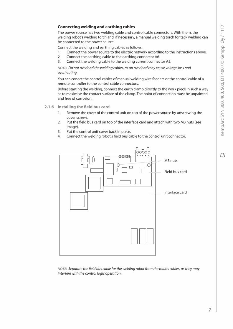
2.1.6 Installing the field bus card1. Remove the cover of the control unit on top of the power source by unscrewing the
cover screws.2. Put the field bus card on top of the interface card and attach with two M3 nuts (see
image).3. Put the control unit cover back in place.4. Connect the welding robot's field bus cable to the control unit connector.
M3 nuts
Field bus card
Interface card
NOTE! Separate the field bus cable for the welding robot from the mains cables, as they may interfere with the control logic operation.
7
Kem
pArc
SYN
300
, 400
, 500
, DT
400
/ © K
empp
i Oy
/ 111
7
EN
2.1.7 Starting the power sourceStart the power source by turning the main switch A2 on the front panel to the I position. The standby indicator A3 turns on.
NOTE! Always turn the device on and off using the main switch, not via the mains socket.
The cooling fan is started for a moment when the main switch is turned to the ‘I’ position. The fan turns off after a while and then restarts during welding when the machine has warmed up sufficiently. The fan continues running even after up to 10 minutes of welding, depending on the temperature of the machine.
2.1.8 Power source indicatorsThe following indicators can be found on the front panel of the power source:
• When the green mains indicator A3 is on, the power source is in standby mode. This indicator is on when the machine is connected to the mains supply with the main switch in the ‘I’ position.
• When the yellow overheating indicator A4 is on, the machine has overheated. When the indicator turns off, the machine can be used again.
• When indicator A4 blinks, the machine has encountered a failure. Attempt to remedy the problem according to the instructions in Section 4, ‘Troubleshooting’. If the failure cannot be eliminated, turn off the machine, and turn it on again. If the failure persists, write down any fault code that may be shown on the display and contact authorised Kemppi service agent.
2.2 CONTROL PANEL
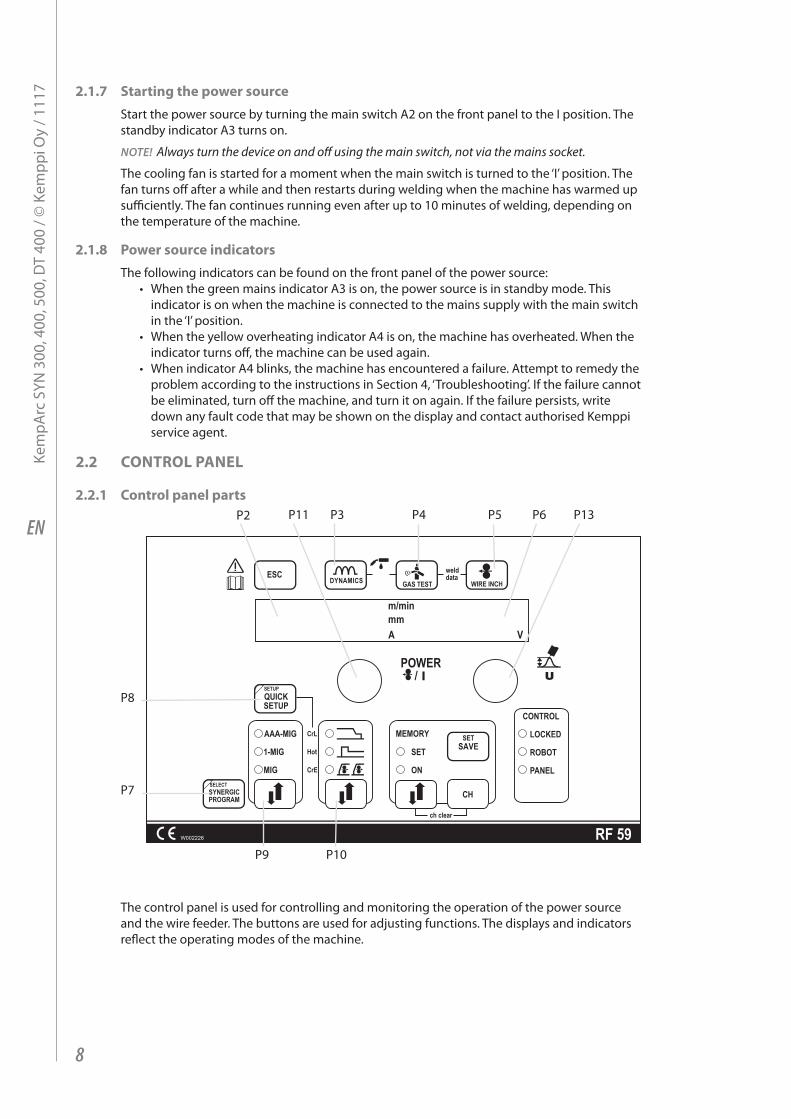
2.2.1 Control panel partsP2 P6P11 P13P5P3 P4
P9 P10
P8
P7
The control panel is used for controlling and monitoring the operation of the power source and the wire feeder. The buttons are used for adjusting functions. The displays and indicators reflect the operating modes of the machine.
8
Kem
pArc
SYN
300
, 400
, 500
, DT
400
/ © K
empp
i Oy
/ 111
7
EN
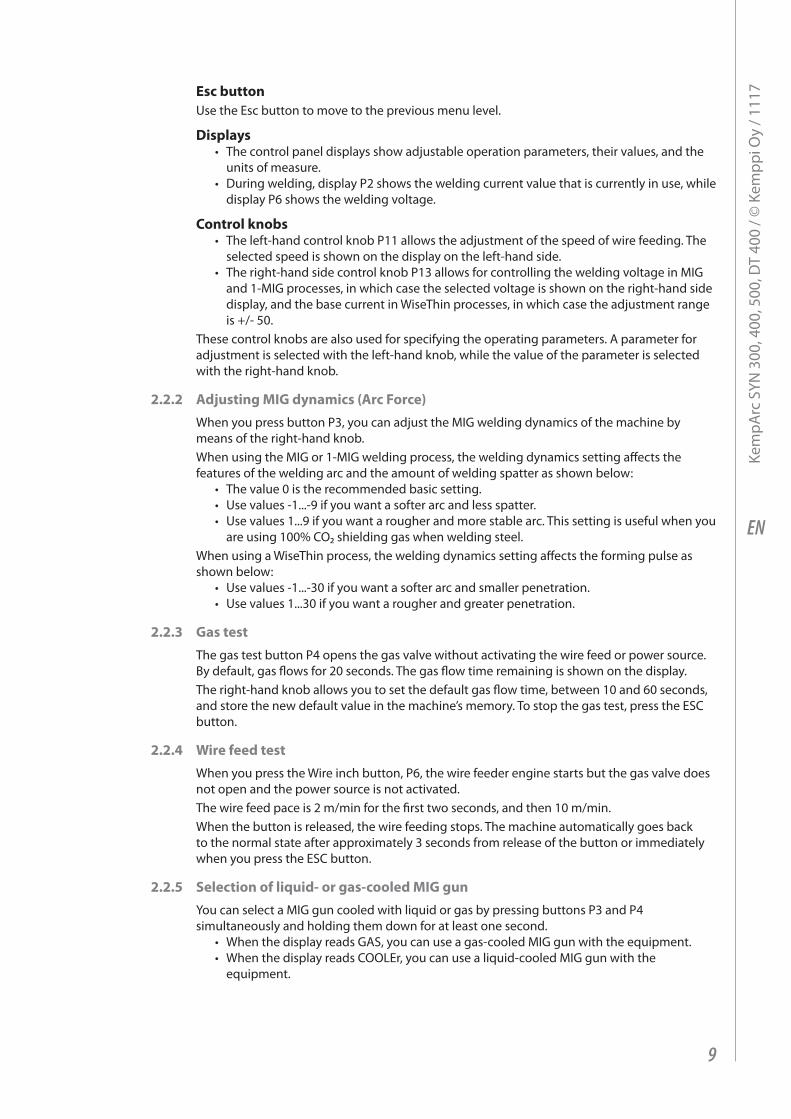
Esc buttonUse the Esc button to move to the previous menu level.
Displays• The control panel displays show adjustable operation parameters, their values, and the
units of measure.• During welding, display P2 shows the welding current value that is currently in use, while
display P6 shows the welding voltage.
Control knobs• The left-hand control knob P11 allows the adjustment of the speed of wire feeding. The
selected speed is shown on the display on the left-hand side.• The right-hand side control knob P13 allows for controlling the welding voltage in MIG
and 1-MIG processes, in which case the selected voltage is shown on the right-hand side display, and the base current in WiseThin processes, in which case the adjustment range is +/- 50.
These control knobs are also used for specifying the operating parameters. A parameter for adjustment is selected with the left-hand knob, while the value of the parameter is selected with the right-hand knob.
2.2.2 Adjusting MIG dynamics (Arc Force)When you press button P3, you can adjust the MIG welding dynamics of the machine by means of the right-hand knob. When using the MIG or 1-MIG welding process, the welding dynamics setting affects the features of the welding arc and the amount of welding spatter as shown below:
• The value 0 is the recommended basic setting.• Use values -1...-9 if you want a softer arc and less spatter.• Use values 1...9 if you want a rougher and more stable arc. This setting is useful when you
are using 100% CO₂ shielding gas when welding steel.When using a WiseThin process, the welding dynamics setting affects the forming pulse as shown below:
• Use values -1...-30 if you want a softer arc and smaller penetration.• Use values 1...30 if you want a rougher and greater penetration.
2.2.3 Gas testThe gas test button P4 opens the gas valve without activating the wire feed or power source. By default, gas flows for 20 seconds. The gas flow time remaining is shown on the display.The right-hand knob allows you to set the default gas flow time, between 10 and 60 seconds, and store the new default value in the machine’s memory. To stop the gas test, press the ESC button.
2.2.4 Wire feed testWhen you press the Wire inch button, P6, the wire feeder engine starts but the gas valve does not open and the power source is not activated. The wire feed pace is 2 m/min for the first two seconds, and then 10 m/min. When the button is released, the wire feeding stops. The machine automatically goes back to the normal state after approximately 3 seconds from release of the button or immediately when you press the ESC button.
2.2.5 Selection of liquid- or gas-cooled MIG gunYou can select a MIG gun cooled with liquid or gas by pressing buttons P3 and P4 simultaneously and holding them down for at least one second.
• When the display reads GAS, you can use a gas-cooled MIG gun with the equipment.• When the display reads COOLEr, you can use a liquid-cooled MIG gun with the
equipment.
9
Kem
pArc
SYN
300
, 400
, 500
, DT
400
/ © K
empp
i Oy
/ 111
7
EN
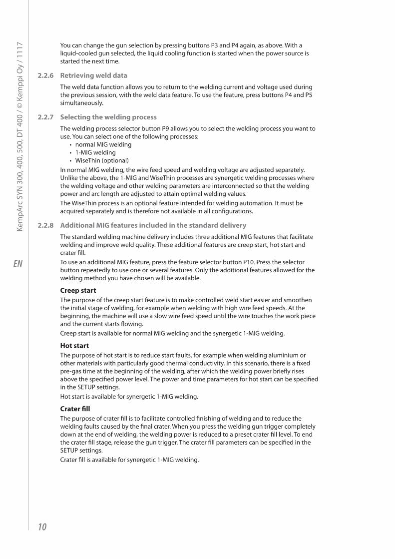
You can change the gun selection by pressing buttons P3 and P4 again, as above. With a liquid-cooled gun selected, the liquid cooling function is started when the power source is started the next time.
2.2.6 Retrieving weld dataThe weld data function allows you to return to the welding current and voltage used during the previous session, with the weld data feature. To use the feature, press buttons P4 and P5 simultaneously.
2.2.7 Selecting the welding processThe welding process selector button P9 allows you to select the welding process you want to use. You can select one of the following processes:
• normal MIG welding• 1-MIG welding • WiseThin (optional)
In normal MIG welding, the wire feed speed and welding voltage are adjusted separately. Unlike the above, the 1-MIG and WiseThin processes are synergetic welding processes where the welding voltage and other welding parameters are interconnected so that the welding power and arc length are adjusted to attain optimal welding values.The WiseThin process is an optional feature intended for welding automation. It must be acquired separately and is therefore not available in all configurations.
2.2.8 Additional MIG features included in the standard deliveryThe standard welding machine delivery includes three additional MIG features that facilitate welding and improve weld quality. These additional features are creep start, hot start and crater fill.To use an additional MIG feature, press the feature selector button P10. Press the selector button repeatedly to use one or several features. Only the additional features allowed for the welding method you have chosen will be available.
Creep startThe purpose of the creep start feature is to make controlled weld start easier and smoothen the initial stage of welding, for example when welding with high wire feed speeds. At the beginning, the machine will use a slow wire feed speed until the wire touches the work piece and the current starts flowing. Creep start is available for normal MIG welding and the synergetic 1-MIG welding.
Hot startThe purpose of hot start is to reduce start faults, for example when welding aluminium or other materials with particularly good thermal conductivity. In this scenario, there is a fixed pre-gas time at the beginning of the welding, after which the welding power briefly rises above the specified power level. The power and time parameters for hot start can be specified in the SETUP settings. Hot start is available for synergetic 1-MIG welding.
Crater fillThe purpose of crater fill is to facilitate controlled finishing of welding and to reduce the welding faults caused by the final crater. When you press the welding gun trigger completely down at the end of welding, the welding power is reduced to a preset crater fill level. To end the crater fill stage, release the gun trigger. The crater fill parameters can be specified in the SETUP settings.Crater fill is available for synergetic 1-MIG welding.
10
Kem
pArc
SYN
300
, 400
, 500
, DT
400
/ © K
empp
i Oy
/ 111
7

EN
Specifying the SETUP settings for additional featuresTo set the values of the functional parameters for additional MIG features, use either the SETUP feature in the control panel (see 2.2.12 "SETUP functions in the control panel") or the QUICK SETUP feature, which you can activate by pressing the QUICK SETUP button, P8.Select the parameter to adjust using the left-hand side control knob P11 or the button P10 and then set the parameter value with the right-hand side control know P13. The value you specified is instantly stored in the control panel memory. The following table lists the parameter values that can be specified for additional MIG features.
Name of parameter
Name displayed
Parameter values Factory setting Description
Creep Start Level Cre 10 ... 170 % 50 % Percent of wire feed speed default 10% refers to slow start, 170% refers to fast start
Hot Start Level Hot -50 ... 75 % 30 % Percent of welding power: -50% refers to cold start +75% refers to hot start
Hot Start Time H2t 0 ... 9.9 s 1.2 s The duration of the hot start in seconds.
Crater Fill Start Level
CrS 10 ... 90 % 90 % The welding power at the beginning of the crater fill stage as a percentage of the welding power preset value.
Crater Fill End Level
CrL 10 ... 90 % 30 % The welding power at the end of the crater fill stage as a percentage of the welding power preset value.
Crater Fill Time Crt 0 ... 9.9 s 2 s The duration of the crater fill stage in seconds.
NOTE! In crater fill, the initial value of the welding power must be greater than the final value, and therefore the adjustment ranges for the initial and final values are restricted automatically, if necessary.
Welding Level
Crater Fill Start Level
Crater Fill Time
Crater Fill End Level
11
Kem
pArc
SYN
300
, 400
, 500
, DT
400
/ © K
empp
i Oy
/ 111
7
EN
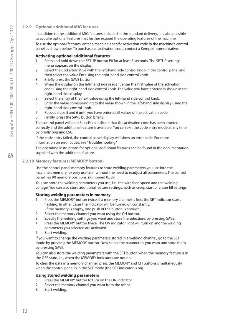
2.2.9 Optional additional MIG featuresIn addition to the additional MIG features included in the standard delivery, it is also possible to acquire optional features that further expand the operating features of the machine. To use the optional features, enter a machine-specific activation code in the machine's control panel as shown below. To purchase an activation code, contact a Kemppi representative.
Activating optional additional features1. Press and hold down the SETUP button P8 for at least 5 seconds. The SETUP settings
menu appears on the display. 2. Select the Cod alternative with the left-hand side control knob in the control panel and
then select the value Ent using the right-hand side control knob.3. Briefly press the SAVE button.4. When the display on the left-hand side reads 1, enter the first value of the activation
code using the right-hand side control knob. The value you have entered is shown in the right-hand side display.
5. Select the entry of the next value using the left-hand side control knob.6. Enter the value corresponding to the value shown in the left-hand side display using the
right-hand side control knob.7. Repeat steps 5 and 6 until you have entered all values of the activation code.8. Finally, press the SAVE button briefly.The control panel will read Suc cEs to indicate that the activation code has been entered correctly and the additional feature is available. You can exit the code entry mode at any time by briefly pressing ESC.If the code entry failed, the control panel display will show an error code. For more information on error codes, see "Troubleshooting". The operating instructions for optional additional features can be found in the documentation supplied with the additional feature.
2.2.10 Memory features (MEMORY button)Use the control panel memory features to store welding parameters you use into the machine's memory for easy use later without the need to readjust all parameters. The control panel has 90 memory positions, numbered 0...89. You can store the welding parameters you use, i.e., the wire feed speed and the welding voltage. You can also store additional feature settings, such as creep start or crater fill settings.
Storing welding parameters in memory1. Press the MEMORY button twice. If a memory channel is free, the SET indicator starts
flashing. In other cases the indicator will be turned on constantly. (If the memory is empty, one push of the button is enough.)
2. Select the memory channel you want using the CH button.3. Specify the welding settings you want and store the selections by pressing SAVE.4. Press the MEMORY button twice. The ON indicator light will turn on and the welding
parameters you selected are activated.5. Start welding.If you want to change the welding parameters stored in a welding channel, go to the SET mode by pressing the MEMORY button. Now select the parameters you want and store them by pressing SAVE.You can also store the welding parameters with the SET button when the memory feature is in the OFF state, i.e., when the MEMORY indicators are not on.To clear the data in a memory channel, press the MEMORY and CH buttons simultaneously when the control panel is in the SET mode (the SET indicator is on).
Using stored welding parameters6. Press the MEMORY button to turn on the ON indicator.7. Select the memory channel you want from the robot.8. Start welding.
12
Kem
pArc
SYN
300
, 400
, 500
, DT
400
/ © K
empp
i Oy
/ 111
7

EN
2.2.11 Synergetic 1-MIG welding and WiseThin weldingIn synergetic 1-MIG welding, the machine selects the optimal welding parameters suitable to the filler wire and shield gas using the programs, or synergetic curves, stored in the control panel. The welder controls the welding by adjusting the welding power and arc length.The synergetic WiseThin process (advanced auto arc) is a synergetic welding process developed for the special needs of robotic welding with weldig characteristics optimised particularly for welding automation.
Selecting a welding program1. Before you start welding, find the welding program suitable to your filler wire and shield
gas in the tables below and then activate the program as follows:2. Press the SYNERGIC PROGRAM button P7 for more than 1 second. This will activate
program selection and the control panel displays start flashing.3. Select the material group with the left-hand side control knob and the welding program
for the material group with the right-hand side control knob according to the tables below. The program you selected is immediately recorded in the memory.
4. Press ESC button or the SYNERGIC PROGRAM button P7 to exit the menu.
MIG programs in the KempArc SYN machine
1-MIG, Fe groupProgram number Wire, mm Material Shield gas
101 0,8 Fe Ar+18%-25%CO2102 0,9 Fe Ar+18%-25%CO2103 1,0 Fe Ar+18%-25%CO2104 1,2 Fe Ar+18%-25%CO2106 1,6 Fe Ar+18%-25%CO2111 0,8 Fe CO2112 0,9 Fe CO2113 1,0 Fe CO2114 1,2 Fe CO2116 1,6 Fe CO2121 0,8 Fe Ar+8%CO2122 0,9 Fe Ar+8%CO2123 1,0 Fe Ar+8%CO2124 1,2 Fe Ar+8%CO2126 1,6 Fe Ar+8%CO2152 0,9 FEMC Ar+18%-25%CO2154 1,2 FEMC Ar+18%-25%CO2164 1,2 FEMC CO2174 1,2 FEFC rutile Ar+18%-25%CO2184 1,2 FEFC rutile CO2194 1,2 FEFC basic Ar+18%-25%CO2
13
Kem
pArc
SYN
300
, 400
, 500
, DT
400
/ © K
empp
i Oy
/ 111
7
EN
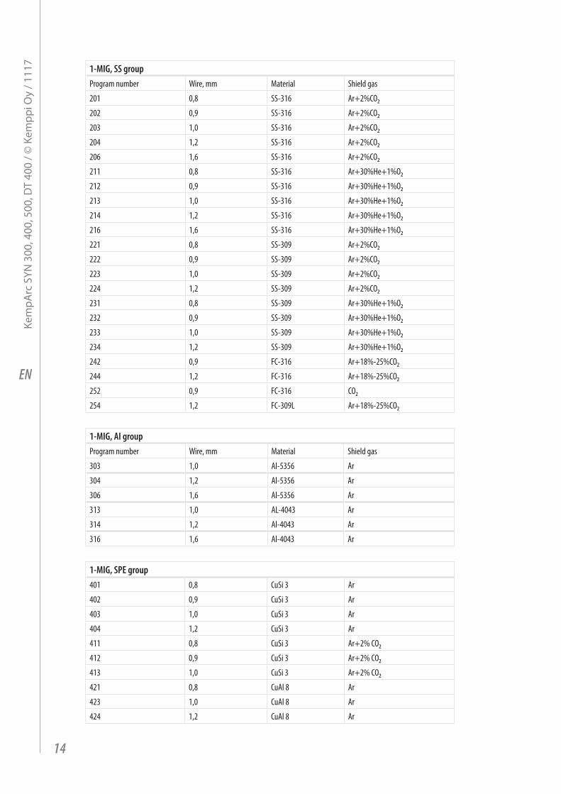
1-MIG, SS groupProgram number Wire, mm Material Shield gas
201 0,8 SS-316 Ar+2%CO2202 0,9 SS-316 Ar+2%CO2203 1,0 SS-316 Ar+2%CO2204 1,2 SS-316 Ar+2%CO2206 1,6 SS-316 Ar+2%CO2211 0,8 SS-316 Ar+30%He+1%O2212 0,9 SS-316 Ar+30%He+1%O2213 1,0 SS-316 Ar+30%He+1%O2214 1,2 SS-316 Ar+30%He+1%O2216 1,6 SS-316 Ar+30%He+1%O2221 0,8 SS-309 Ar+2%CO2222 0,9 SS-309 Ar+2%CO2223 1,0 SS-309 Ar+2%CO2224 1,2 SS-309 Ar+2%CO2231 0,8 SS-309 Ar+30%He+1%O2232 0,9 SS-309 Ar+30%He+1%O2233 1,0 SS-309 Ar+30%He+1%O2234 1,2 SS-309 Ar+30%He+1%O2242 0,9 FC-316 Ar+18%-25%CO2244 1,2 FC-316 Ar+18%-25%CO2252 0,9 FC-316 CO2254 1,2 FC-309L Ar+18%-25%CO2
1-MIG, AI groupProgram number Wire, mm Material Shield gas
303 1,0 Al-5356 Ar
304 1,2 Al-5356 Ar
306 1,6 Al-5356 Ar
313 1,0 AL-4043 Ar
314 1,2 Al-4043 Ar
316 1,6 Al-4043 Ar
1-MIG, SPE group401 0,8 CuSi 3 Ar
402 0,9 CuSi 3 Ar
403 1,0 CuSi 3 Ar
404 1,2 CuSi 3 Ar
411 0,8 CuSi 3 Ar+2% CO2412 0,9 CuSi 3 Ar+2% CO2413 1,0 CuSi 3 Ar+2% CO2421 0,8 CuAl 8 Ar
423 1,0 CuAl 8 Ar
424 1,2 CuAl 8 Ar
14
Kem
pArc
SYN
300
, 400
, 500
, DT
400
/ © K
empp
i Oy
/ 111
7

EN
WiseThin, Fe group903 1,0 Fe Ar+18%-25%CO2904 1,2 Fe Ar+18%-25%CO2913 1,0 Fe CO²914 1,2 Fe CO²
WiseThin, SS group923 1,0 SS-316 Ar+2%CO2924 1,2 SS-316 Ar+2%CO2933 1,0 SS-316 Ar+30%He+1%O2934 1,2 SS-316 Ar+30%He+1%O2
Using the welding program5. Select the welding process 1-MIG with the P9 button. 6. Press the SYNERGIC PROGRAM button to display the material group and the welding
program number. Make sure that the welding program corresponds to the filler wire and shield gas you use.
7. Check the wire type and shield gas for the welding program in the table below.8. Adjust the welding power with the left-hand side knob and the arc length with the right-
hand side knob.
2.2.12 SETUP features of the control panelThe machine has a number of additional features, or parameters, whose settings can be specified with the control panel's SETUP function as follows:1. Press and hold down the SETUP button P10 for at least 5 seconds. 2. Select the parameter to adjust using the left-hand side control knob. The parameter
name is shown in display 2. 3. Specify the parameter value with the right-hand side control knob. The selected value is
shown in the display P6. The parameter’s value is immediately stored in the memory. 4. You can exit the SETUP mode by pressing and holding down the SETUP button again for
at least 5 seconds or by briefly pressing the ESC button. All welding processes have their own SETUP parameters. For example, adjusting the post-current for synergetic MIG welding does not affect the post-current of normal MIG welding.The tables below show the additional features available in this welding machine and their possible values.
Normal MIG welding parameters and their valuesName of parameter
Name displayed
Parameter values
Factory setting Description
Pre Gas Time PrG 0.0 ... 9.9 s 0.0 s Pre-gas time 0 ... 9.9 s.
Post Gas Time PoG Aut, 0.1 ... 32.0 s 1,0 Post gas time, Aut = Automatic, depending on welding current 0.1 ... 32 s
Creep Start Level Cre 10 ... 170% 50 % Percentage of wire feed speed, 10% refers to slow start, 170% to accelerated start
Post Current Time PoC -9 ... +9 0 Post-welding current time
15
Kem
pArc
SYN
300
, 400
, 500
, DT
400
/ © K
empp
i Oy
/ 111
7
EN
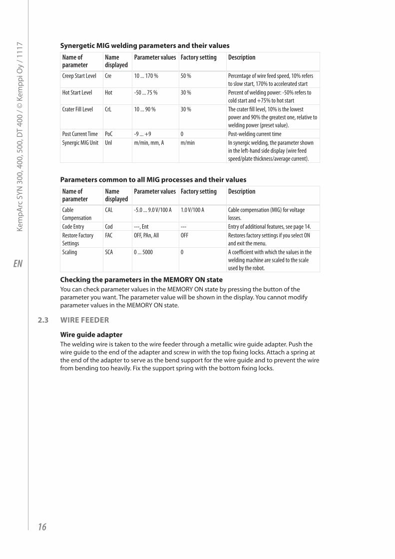
Synergetic MIG welding parameters and their values
Name of parameter
Name displayed
Parameter values Factory setting Description
Creep Start Level Cre 10 ... 170 % 50 % Percentage of wire feed speed, 10% refers to slow start, 170% to accelerated start
Hot Start Level Hot -50 ... 75 % 30 % Percent of welding power: -50% refers to cold start and +75% to hot start
Crater Fill Level CrL 10 ... 90 % 30 % The crater fill level, 10% is the lowest power and 90% the greatest one, relative to welding power (preset value).
Post Current Time PoC -9 ... +9 0 Post-welding current timeSynergic MIG Unit Unl m/min, mm, A m/min In synergic welding, the parameter shown
in the left-hand side display (wire feed speed/plate thickness/average current).
Parameters common to all MIG processes and their values
Name of parameter
Name displayed
Parameter values Factory setting Description
Cable Compensation
CAL -5.0 ... 9.0 V/100 A 1.0 V/100 A Cable compensation (MIG) for voltage losses.
Code Entry Cod ---, Ent --- Entry of additional features, see page 14.Restore Factory Settings
FAC OFF, PAn, All OFF Restores factory settings if you select ON and exit the menu.
Scaling SCA 0 ... 5000 0 A coefficient with which the values in the welding machine are scaled to the scale used by the robot.
Checking the parameters in the MEMORY ON stateYou can check parameter values in the MEMORY ON state by pressing the button of the parameter you want. The parameter value will be shown in the display. You cannot modify parameter values in the MEMORY ON state.
2.3 WIRE FEEDER
Wire guide adapterThe welding wire is taken to the wire feeder through a metallic wire guide adapter. Push the wire guide to the end of the adapter and screw in with the top fixing locks. Attach a spring at the end of the adapter to serve as the bend support for the wire guide and to prevent the wire from bending too heavily. Fix the support spring with the bottom fixing locks.
16
Kem
pArc
SYN
300
, 400
, 500
, DT
400
/ © K
empp
i Oy
/ 111
7
EN
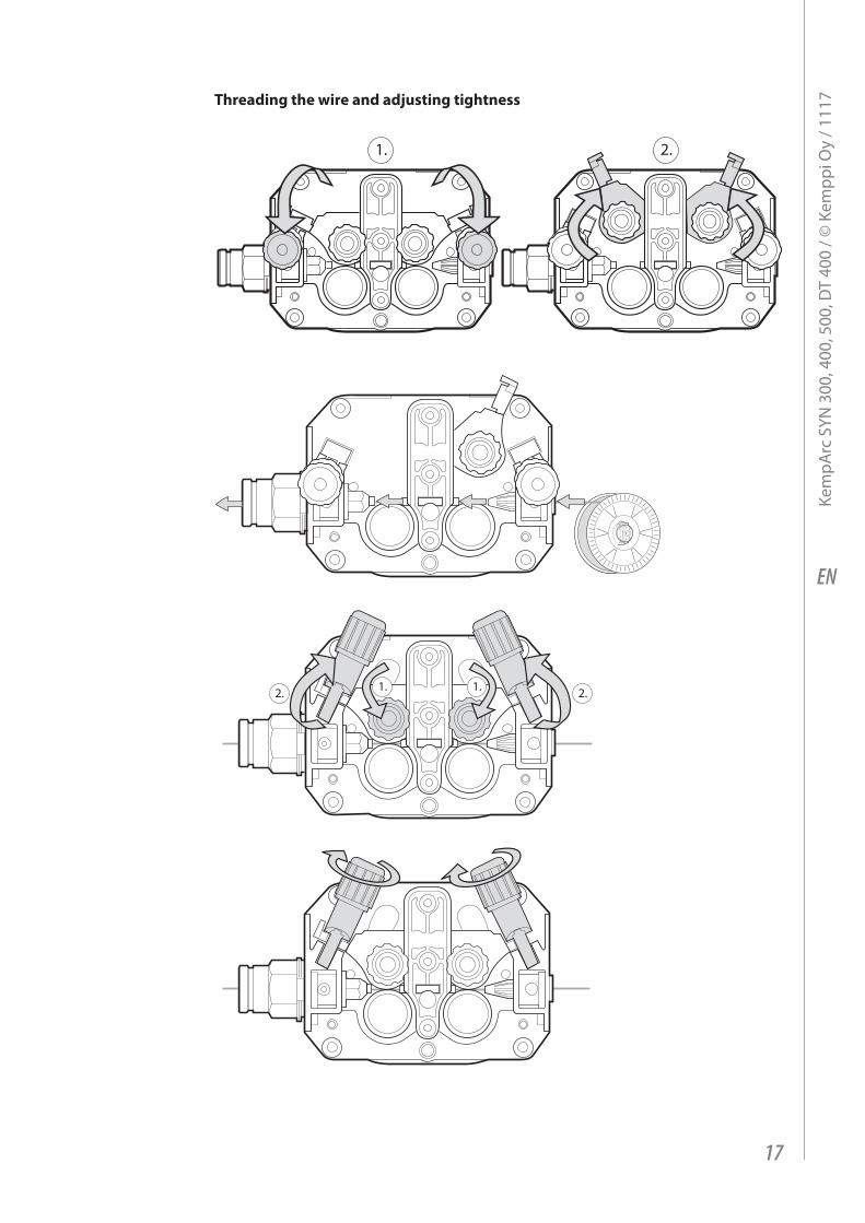
Threading the wire and adjusting tightness
1. 2.
1. 1. 2.2.
17
Kem
pArc
SYN
300
, 400
, 500
, DT
400
/ © K
empp
i Oy
/ 111
7

EN
3. MAINTENANCEThe utilisation level of the power source and its working environment should be taken into consideration in planning the frequency of maintenance of the machine. Proper use of the machine and regular maintenance help you avoid unnecessary downtime and failures.
3.1 CABLES• Check the condition of welding and mains cables daily. • Make sure to replace damaged cables immediately. Only use original Kemppi spare
parts.• Make sure that all extension cables used in the mains connection are in proper condition
and compliant with regulations.
NOTE! The mains cables may be repaired and installed only by electrical contractors and installers authorised to perform such operations.
3.2 POWER SOURCEBefore cleaning the interior of the machine, you need to remove the case by unscrewing the mounting screws of the machine.
NOTE! To prevent damage, wait approximately two minutes after disconnecting the mains cable before removing the machine’s case.
Perform the following cleaning and maintenance at least every six months:1. Clean the interior of the machine and the fan grill’s net of any dust and stains – for
example, with a soft brush and vacuum cleaner.• Do not use pressurised air. The stain may become compressed into the grooves of the
coolers.• Do not use a pressure-washing device.
2. Check the electrical connections of the machine. Clean any oxidised connections, and tighten the loosened ones.
• Check for the right tension before tightening the connections.
NOTE! Remember that the machine may be repaired only by an electrical contractor or installer authorised to perform such operations.
18
Kem
pArc
SYN
300
, 400
, 500
, DT
400
/ © K
empp
i Oy
/ 111
7

EN
3.2.1 DuraTorque™ 400, 4-wheel wire feeder mechanism
Wire guide tubes
Ss, Al, Fe, Mc, Fc
ø 0.6...1.6 mm ø 2.5/64 mm, W000762, silver, plastic
ø 2.5/33 mm, W000956, silver, plastic
ø 2.0 mm, W000624, plastic
ø 1.6..0.20.4 mm
ø 3.5/64 mm, W001430, silver, plastic
ø 3.5/33 mm, W001431, silver, plastic
ø 3.5 mm, W001389, plastic
Fe, Mc, Fc ø 0.6..0.00.8 mm
ø 1.0/67 mm, W001432, white, steel
ø 2.0/33 mm, W001435, orange, steel
ø 2.0 mm, W000624, plastic
ø 0.9...1.6 mm ø 2.0/64 mm, W001433, orange, steel
ø 3.5 mm, W001389, plastic
ø 1.6..0.20.4 mm
ø 4.0/63 mm, W001434, blue, steel
ø 4.0/33 mm, W001436, blue, steel
ø 3.5 mm, W001391, brass
24.8.2005 12:55
2.
1.
Parts of the DT400 metal feed rollsW000731 gear ring 1 driving 2 pcs per unit
W000732 gear ring 2 pressing 2 pcs per unit
W000711 drive ring V groove 1,2/1,2 optional 4 pcs per unit
W000718 drive ring V groove 1,0/1,0 optional 4 pcs per unit
W000891 drive ring V groove 1,0/1,2 optional 4 pcs per unit
9420507 washer 10.5x30x2.5 2 pcs per unit
3.3 REGULAR MAINTENANCEMake sure that the machine receives regular and appropriate maintenance. Authorised Kemppi service agents perform regular maintenance by agreement. For more information on regular maintenance, contact a Kemppi representative.
19
Kem
pArc
SYN
300
, 400
, 500
, DT
400
/ © K
empp
i Oy
/ 111
7

EN
3.4 DISPOSAL OF THE MACHINE
Do not dispose of electrical equipment with normal waste!In observance of European Directive 2002/96/EC on waste electrical and electronic equipment, and its implementation in accordance with national law, electrical equipment that has reached the end of its life must be collected separately and taken to an appropriate environmentally responsible recycling facility. The owner of the equipment is obliged to deliver a decommissioned unit to a regional collection centre, per the instructions of local authorities or a Kemppi representative. By applying this European Directive you will improve the environment and human health.
4. TROUBLESHOOTINGIn the event of a failure of the machine, contact an authorised Kemppi service agent. Before taking your unit for servicing, check the list below.
4.1 OVERLOAD (YELLOW INDICATOR LIT)Two simultaneously operating fans cool the power source. The machine may, however, overheat if continuously loaded above the rated values or if the circulation of cooling air is prevented.Overheating is indicated by a yellow indicator light in the front panel of the power source. You then need to stop welding and let the machine cool down. The indicator light turns off when welding can be resumed.
4.2 CONTROL CABLE CONNECTOR FUSEThe back panel of the power source has a fuse that protects the control cable connector. Using an incorrect type of fuse will damage the power source. Therefore, it is important that you always use the correct fuse type. The type and size of the fuse are indicated next to the fuse socket.
4.3 ELECTRIC NETWORK OVERVOLTAGE OR UNDERVOLTAGEIf the power source is used in an electric network with insufficient voltage (less than 300 V), the control features of the device are automatically disabled.The primary circuits of the power source are protected against power spikes. The product’s mains voltage range is broad enough to prevent over-voltage problems at up to 440 V. Make sure that the voltage remains within the allowed range, especially if the operating power is supplied by a generator set. For information on the allowable voltage range, see "Technical specifications" in this guide.
4.4 MISSING PHASE IN THE ELECTRIC NETWORKIf a phase is missing from the mains current, the welding features will be adversely affected or the machine may have problems starting. Loss of a phase can be caused by a:
• Blown mains fuse• Damaged mains cable• Poor mains cable connection in the machine’s terminal block or mains socket
4.5 ERROR CODESThe machine always checks its operation automatically during start-up and reports any failures detected. If failures are detected during start-up, they are shown as error codes on the control panel display.
Err3: Power source overvoltageThe machine has stopped the welding because it has detected momentary voltage spikes or continuous overvoltage dangerous to the machine in the electric network. Check the quality of the supply network.
20
Kem
pArc
SYN
300
, 400
, 500
, DT
400
/ © K
empp
i Oy
/ 111
7

EN
Err4: Power source overheatingThe power source has overheated. The cause may be one of the following:
• The power source has been used for a long time at maximum power.• The circulation of cooling air to the power source is blocked.• The cooling system has experienced a failure.
Remove any obstacle to air circulation, and wait until the power source fan has cooled down the machine.
Err5 Water unit alarmThe water circulation is blocked. The cause may be one of the following:
• Congestion or disconnection in the cooling pipeline• Insufficient cooling liquid• Excessive cooling liquid temperature
Check the circulation of the cooling liquid and the air circulation of the water unit.
Err23: Power source overvoltage warningThe power source has detected voltage spikes in the electric network. Short power spikes can be managed. They do not lead to interruptions in welding but may decrease the welding quality. Check the quality of the supply network.
Err61: The water unit is not foundThe water unit is not connected to the equipment, or the connection has failed. Connector the water unit.
Other error codes:If an error code not listed above is shown, contact Kemppi service and tell them the error code.
21
Kem
pArc
SYN
300
, 400
, 500
, DT
400
/ © K
empp
i Oy
/ 111
7
EN
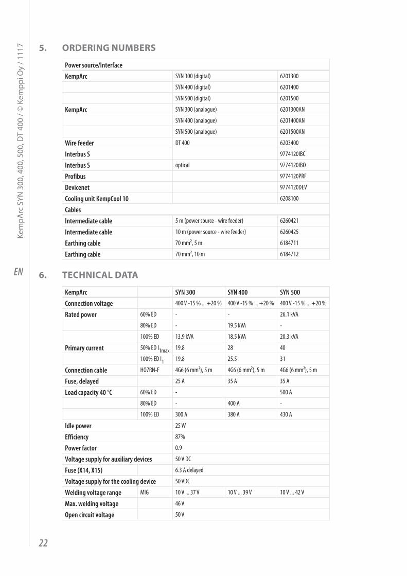
5. ORDERING NUMBERS
Power source/InterfaceKempArc SYN 300 (digital) 6201300
SYN 400 (digital) 6201400
SYN 500 (digital) 6201500
KempArc SYN 300 (analogue) 6201300AN
SYN 400 (analogue) 6201400AN
SYN 500 (analogue) 6201500AN
Wire feeder DT 400 6203400
Interbus S 9774120IBC
Interbus S optical 9774120IBO
Profibus 9774120PRF
Devicenet 9774120DEV
Cooling unit KempCool 10 6208100
CablesIntermediate cable 5 m (power source - wire feeder) 6260421
Intermediate cable 10 m (power source - wire feeder) 6260425
Earthing cable 70 mm², 5 m 6184711
Earthing cable 70 mm², 10 m 6184712
6. TECHNICAL DATA
KempArc SYN 300 SYN 400 SYN 500Connection voltage 400 V -15 % ... +20 % 400 V -15 % ... +20 % 400 V -15 % ... +20 %
Rated power 60% ED - - 26.1 kVA
80% ED - 19.5 kVA -
100% ED 13.9 kVA 18.5 kVA 20.3 kVA
Primary current 50% ED I1max 19.8 28 40
100% ED I1 19.8 25.5 31
Connection cable HO7RN-F 4G6 (6 mm²), 5 m 4G6 (6 mm²), 5 m 4G6 (6 mm²), 5 m
Fuse, delayed 25 A 35 A 35 A
Load capacity 40 °C 60% ED - 500 A
80% ED - 400 A -
100% ED 300 A 380 A 430 A
Idle power 25 W
Efficiency 87%
Power factor 0.9
Voltage supply for auxiliary devices 50 V DC
Fuse (X14, X15) 6.3 A delayed
Voltage supply for the cooling device 50 VDC
Welding voltage range MIG 10 V ... 37 V 10 V ... 39 V 10 V ... 42 V
Max. welding voltage 46 V
Open circuit voltage 50 V
22
Kem
pArc
SYN
300
, 400
, 500
, DT
400
/ © K
empp
i Oy
/ 111
7

EN
KempArc SYN 300 SYN 400 SYN 500Operating temperature range
-20 ... +40 °C -20 ... +40 °C -20 ... +40 °C
Storage temperature range -40 ... +60 °C -40 ... +60 °C -40 ... +60 °C
Degree of protection IP23S IP23S IP23S
EMC class A A A
Minimun short circuit power Ssc of supply network *
- 4.7 4.6
External dimensions LxWxH 590x230x500 mm 590x230x500 mm 590x230x500 mm
Weight 35 kg 36 kg 37 kg* See paragraph 2.1.3.
DT 400Operating voltage 50 V DC
Rated power 100 W
Load capacity 80% ED 600 A
100% ED 500 A
Operating principle 4-wheel feed
Wire feed speed 0 ... 25 m/min
Filler wires ø Fe, Ss 0.6 – 1.6 mm
ø Flux-cored wire 0.8 – 1.6 mm
ø Al 1.0 – 1.6 mm
Welding gun connector Euro
Operating temperature range -20 ... +40 °C
Storage temperature range -40 ... +60 °C
Degree of protection IP23S
External dimensions LxWxH 269x175x169 mm
Weight 4.5 kg
23
Kem
pArc
SYN
300
, 400
, 500
, DT
400
/ © K
empp
i Oy
/ 111
7

www.kemppi.c om 1920130 1117
KEMPPI OYHennalankatu 39PL 13FIN-15801 LAHTIFINLANDTel +358 3 899 11Telefax +358 3 899 [email protected]
Kotimaan myynti:Tel +358 3 899 11Telefax +358 3 734 [email protected]
KEMPPI SVERIGE ABBox 717S-194 27 UPPLANDS VÄSBYSVERIGETel +46 8 590 783 00Telefax +46 8 590 823 [email protected]
KEMPPI NORGE A/SPostboks 2151, PostterminalenN-3103 TØNSBERGNORGETel +47 33 346000Telefax +47 33 [email protected]
KEMPPI DANMARK A/SLiterbuen 11DK-2740 SKOVLUNDEDANMARKTel +45 4494 1677Telefax +45 4494 [email protected]
KEMPPI BENELUX B.V.Postbus 5603NL-4801 EA BREDANEDERLANDTel +31 765717750Telefax +31 [email protected]
KEMPPI (UK) LtdMartti Kemppi BuildingFraser RoadPriory Business ParkBEDFORD, MK44 3WHUNITED KINGDOMTel +44 (0)845 6444201Telefax +44 (0)845 [email protected]
KEMPPI FRANCE S.A.S.65 Avenue de la Couronne des Prés78681 EPONE CEDEXFRANCETel +33 1 30 90 04 40Telefax +33 1 30 90 04 [email protected]
KEMPPI GmbHOtto-Hahn-Straße 14D-35510 BUTZBACHDEUTSCHLANDTel +49 6033 88 020Telefax +49 6033 72 [email protected]
KEMPPI SPÓŁKA Z O.O.Ul. Borzymowska 3203-565 WARSZAWAPOLANDTel +48 22 7816162Telefax +48 22 [email protected]
KEMPPI AUSTRALIA PTY LTD.13 Cullen PlaceP.O. Box 5256, Greystanes NSW 2145SMITHFIELD NSW 2164 AUSTRALIATel. +61 2 9605 9500Telefax +61 2 9605 [email protected]
OOO KEMPPIPolkovaya str. 1, Building 6127018 MOSCOWRUSSIATel +7 495 739 4304Telefax +7 495 739 [email protected]
ООО КЕМППИул. Полковая 1, строение 6127018 МоскваTel +7 495 739 4304Telefax +7 495 739 [email protected]
KEMPPI, TRADING (BEIJING) COMPANY, LIMITEDRoom 420, 3 Zone, Building B,No.12 Hongda North Street,Beijing Economic Development Zone,100176 BeijingCHINATel +86-10-6787 6064+86-10-6787 1282Telefax +86-10-6787 [email protected]
肯倍贸易(北京)有限公司中国北京经济技术开发区宏达北路12号创新大厦B座三区420室 (100176)电话: +86-10-6787 6064+86-10-6787 1282传真: +86-10-6787 [email protected]
KEMPPI INDIA PVT LTDLAKSHMI TOWERSNew No. 2/770, First Main Road, KAZURA Gardens, Neelangarai, CHENNAI - 600 041 TAMIL NADUTel +91-44-4567 1200Telefax +91-44-4567 [email protected]