Kelly, M.E. and Phillips, C. and Scheurich, F. and Kim, H ...
16
Kelly, M.E. and Phillips, C. and Scheurich, F. and Kim, H.W. and Fletcher, T.M. and Brown, R.E. (2009) Applying rotorcraft modelling technology to renewable energy research. In: 2nd AHS/KSASS International Forum on Rotorcraft Multidiscipllinary Technology , 19-20 October 2009, Seoul, Korea. http://strathprints.strath.ac.uk/27490/ Strathprints is designed to allow users to access the research output of the University of Strathclyde. Copyright © and Moral Rights for the papers on this site are retained by the individual authors and/or other copyright owners. You may not engage in further distribution of the material for any profitmaking activities or any commercial gain. You may freely distribute both the url (http://strathprints.strath.ac.uk ) and the content of this paper for research or study, educational, or not-for-profit purposes without prior permission or charge. You may freely distribute the url (http://strathprints.strath.ac.uk) of the Strathprints website. Any correspondence concerning this service should be sent to The Strathprints Administrator: [email protected]
Transcript of Kelly, M.E. and Phillips, C. and Scheurich, F. and Kim, H ...

Kelly, M.E. and Phillips, C. and Scheurich, F. and Kim, H.W. and Fletcher, T.M. and Brown, R.E. (2009) Applying rotorcraft modelling technology to renewable energy research. In: 2nd AHS/KSASS International Forum on Rotorcraft Multidiscipllinary Technology , 19-20 October 2009, Seoul, Korea.
http://strathprints.strath.ac.uk/27490/
Strathprints is designed to allow users to access the research output of the University of Strathclyde. Copyright © and Moral Rights for the papers on this site are retained by the individual authors and/or other copyright owners. You may not engage in further distribution of the material for any profitmaking activities or any commercial gain. You may freely distribute both the url (http://strathprints.strath.ac.uk) and the content of this paper for research or study, educational, or not-for-profit purposes without prior permission or charge. You may freely distribute the url (http://strathprints.strath.ac.uk) of the Strathprints website. Any correspondence concerning this service should be sent to The Strathprints Administrator: [email protected]

Applying Rotorcraft Modelling Technology to
Renewable Energy Research
Mary E. Kelly, Catriona Phillips, Frank Scheurich∗
Hyo Won Kim, Timothy M. Fletcher†
Richard E. Brown‡
Rotor Aeromechanics Laboratory
Department of Aerospace Engineering
University of Glasgow
Glasgow, G12 8QQ, Scotland
Abstract
The perceived need to reduce mankind’s impact on the global climate motivates towards a future societyin which a significant proportion of its energy needs will be extracted from the winds and the tides ofthe planet. This paper shows several examples of the application of Brown’s Vorticity Transport Model,originally developed to perform simulations of helicopter aeromechanics and wake dynamics, to the analysisof the performance of renewable energy devices and their possible impact on the environment. Predictionof the loading on wind turbines introduces significant additional challenges to such a model, includingthe need to account fully for the effects of radial flow on blade stall. The wake-mediated aerodynamicinteractions that occur within a wind farm can reduce its power output significantly, but this problemis very similar to that where the aerodynamic unsteadiness of the coupled wake of the main and tailrotors of a helicopter can result in significantly increased pilot workload. The helicopter-related problemof brownout, encountered during operations in desert conditions, has its analogue in the entrainment ofsediment into the wakes of tidal turbines. In both cases it may be possible to ameliorate the influence ofthe rotor on its environment by careful and well-informed design. Finally, calculations of the distortionand dispersal of the exhaust plumes of a helicopter by the wake of its rotor allow insight into how windturbines might interfere with the dispersal of pollutants from nearby industrial sites. These examplesshow how cross-disciplinary information transfer between the rotorcraft field and the renewable energycommunity is helping to develop the technologies that will be required by our future society, as well ashelping to understand the environmental issues that might need to be faced as these technologies becomemore prevalent.
Notation
CP rotor power coefficientCT rotor thrust coefficientd particle (effective) diameterR rotor radiusr blade spanwise coordinateS vorticity sourceSp source of particulates into the flowt timeu flow velocityub velocity of blade with respect to airug particulate fallout velocityV∞ freestream velocity
∗ Postgraduate Research Students† Postdoctoral Research Assistants‡ Mechan Professor of Engineering
Presented at the American Helicopter Society InternationalForum on Rotorcraft Multidisciplinary Technology, Seoul,Korea, 19–20 October, 2009. Copyright c© 2009 by theAmerican Helicopter Society International, Inc. All rightsreserved.
λ tip-speed ratio, (ΩR)/V∞µ advance ratio, V∞/(ΩR)µ? thrust-normalized advance ratio, µ/
√CT /2
ν kinematic viscosity of flowνp diffusion coefficient for particulatesρ air densityρp density of suspended particulatesρs material density of particleΩ rotor rotational speedω vorticity, ∇× uωb vorticity bound to blade
Introduction
Mankind is slowly coming to a consensus that thecontinued emission of large quantities of carboninto the atmosphere is likely to alter significantlythe climate on the earth through the mechanismknown as the ‘greenhouse effect’. One of the largestcontributors to elevated levels of atmospheric car-bon is the electricity generation industry. There is
1

significant interest within this community in meth-ods that may be used to ameliorate its impact onatmospheric carbon levels. One of the most promis-ing ways to do this appears to be through the ex-ploitation of wind and tidal energy resources, us-ing turbines to meet a significant proportion of theEarth’s future electricity requirement.
Wind turbines are the fastest growing of the re-newable energy technologies in Scotland. Most tur-bines in the European Union produce electricity atan average of 25% of their rated maximum power asa result of the intermittency of wind resources, butScotland’s particular wind regime enables an aver-age of 40% or higher on the western and northerncoasts (Ref. 1).
There are now numerous large on-shore windfarms in Scotland, including Black Law rated atover 96MW, Hadyard Hill, which is the first windfarm in the UK able to generate over 100MW,and Whitelee, a 322MW project under construc-tion that is already the largest onshore wind farmin Europe. It is estimated that 11.5GW of onshorewind potential exists, enough to provide 45TWhof energy per year. More than double this capacityexists on offshore sites, where mean wind speeds aregreater than on land. The total offshore potential isestimated at 25GW, which although more expen-sive to install than land-based systems, could beenough to provide almost half the total electricityused in Scotland (Ref. 2).
Unlike the winds in the atmosphere, the tides inthe ocean provide an inherently predictable sourceof power. The few operational schemes for captur-ing energy from the flow of tides rely on underwaterplant that is based quite closely on wind turbinetechnology. Tidal turbine technology is still in itsinfancy, however, with one of the few commercial-scale tidal turbine in the world being the Ma-rine Current Turbines SeaGen 1.2MW device atStrangford Lough in Northern Ireland. The Pent-land Firth between Orkney and mainland Scotlandhas been described as the “Saudi Arabia of tidalpower,” however, and may be capable of providingup to 10GW of power (Ref. 3). The overall aims ofthe Scottish Government are ambitious, with cur-rent plans to generate at least 50% of domestic en-ergy requirements from renewable sources by theyear 2020. Concurrent with these ambitions is amajor programme of investment, both in the tech-nologies and in the scientific basis that is requiredto meet this challenge.
The problems faced by those who would designand deploy tidal and wind turbines are, in someways, very similar to those experienced by heli-copter engineers. In addition, many recent devel-opments in the rotorcraft world, such as the ac-tive control of rotors and the use of adaptive com-posite technology, are slowly finding their way into
the turbine field. In this paper, several interestingapplications of Brown’s Vorticity Transport Model(VTM) to the analysis of wind and tidal turbineswill be described. The VTM was originally devel-oped to study rotorcraft aerodynamic and flight dy-namic problems, and its exploitation in the renew-able energy field shows some interesting examplesof cross-disciplinary transfer of technology from therotorcraft field.
Two types of turbine are most often encounteredin practice. In the more common horizontal-axisconfiguration, the axis of the turbine is aligned,nominally, with the oncoming wind or water. Thebehaviour of the turbine bears some resemblanceto that of a helicopter rotor in axial flight, partic-ularly when operating under steady conditions inwhich case the rotor induces a component of veloc-ity in opposition to the oncoming flow, and hencean expanding wake tube as in the rotor windmillbrake state. In a vertical-axis turbine, the axis ofrotation of the rotor is oriented transversely to theoncoming flow. Given that the orientation of theblades of the turbine is generally parallel to theaxis of rotation, the connection of the behaviour ofthis type of turbine to that of helicopter rotors issomewhat more tenuous than that of a horizontal-axis device, although there are still some distinctsimilarities.
Computational Model
The present formulation of the Vorticity TransportModel (VTM), developed by Brown (Ref. 4) andextended by Brown and Line (Ref. 5) couples alifting-line model for the aerodynamics of the bladeto an Eulerian representation of the vorticity in theflow field.
Figure 1: VTM-predicted wake geometry of the HART-II rotor and drive enclosure. The system is in a de-scending flight condition at advance ratio µ=0.151.
2

The flow field is evolved by solution of theNavier-Stokes equations in vorticity-velocity formon a structured Cartesian grid. Assuming incom-pressible flow with velocity, u, the associated vor-ticity distribution ω = ∇× u evolves according tothe unsteady vorticity transport equation
∂
∂tω + u · ∇ω − ω · ∇u = S + ν∇2ω (1)
where ν is the kinematic viscosity of the fluid. Thelocal rate of numerical diffusion is controlled veryeffectively by using a set of highly-compressive fluxlimiters within the particular implementation ofToro’s Weighted Average Flux method (Ref. 6)that is used within the code to convect the solu-tion through time. At each time step, the velocityat the cell faces is obtained from the vorticity dis-tribution using a fast multipole technique to invertthe differential form of the Biot-Savart equation
∇2u = −∇× ω. (2)
A semi-Lagrangian adaptive grid is used to trackthe evolving vorticity in such a way that cells onlyexist in regions of the computational domain wherethe vorticity is non-zero. As the vorticity movesto a new location, new cells are created and anycells that no longer contain vorticity are destroyed.Thus, the grid structure is free to follow the evo-lution of the wake, eliminating the requirement forexplicit numerical boundary conditions at the edgeof the computational domain and increasing thecomputational efficiency of the method. Moreover,a nested grid system allows for fine resolution closeto the rotor and then a systematic decrease in res-olution with distance from the rotor hub.
An extension of the Weissinger-L formulation oflifting-line theory is implemented on a series of dis-crete panels along the length of each rotor blade toyield the aerodynamic loading. A bound vortex isattached to the quarter-chord of each panel. Thestrength of the bound vorticity along the lengthof the blade is determined by enforcing, simulta-neously, a condition of zero through-flow on a setof aerodynamic stations located at the 3/4 chordof each panel. As the computation is progressedthrough each time step, trailed and shed vortic-ity from each vortex panel is added to the nearwake downstream of the blade as the local vortic-ity source,
S = − d
dtωb + ub∇ · ωb, (3)
where ωb is the bound vorticity. The two-dimensional aerodynamic characteristics of the ro-tor blade sections are specified in a look-up tableas a function of angle of attack and Mach numberfor a given Reynolds number. These characteristicscan be used to precondition the boundary condition
that is applied at the control points to allow the lift-ing line calculation to match closely the sectionalaerodynamic characteristics, including stall, of theactual blade. As this approach is still essentiallyinviscid, the profile drag of the blade is calculatedas a separate function of local angle of attack andis then added to the local aerodynamic force thatis calculated from the lifting line model.
Fuselages or other solid bodies are representedusing an unsteady vortex panel method, as de-scribed in Ref. 7. The surface of any body im-mersed in the flow-field is discretised into a sys-tem of panels, such that each panel edge is repre-sented as a vortex filament with constant strength,forming a closed loop of vorticity. The velocity atthe centroid of any panel is calculated as the sumof the influences from all vortex filaments on thebody together with the velocity induced by all theother vorticity within the flow. To determine thestrengths of the vortex loops, a boundary conditionof zero through-flow is enforced simultaneously atthe centroids of all panels.
The equations of motion for the blades, as forcedby the aerodynamic load along their span, arederived by automatic differentiation of the La-grangian of the system. No small-angle approx-imations are involved in this approach and thecoupled flap-lag-feather dynamics of each of theblades, where appropriate, is fully represented. Inall the examples presented in this paper, however,the blades themselves were assumed to be rigid.
The VTM has been applied extensively to theanalysis of helicopter aerodynamic problems. TheVTM has been used successfully to investigate theflight dynamics associated with penetration intothe wakes of fixed-wing aircraft (Ref. 8), and forthe study of helicopter main rotor - fuselage inter-action (Ref. 7). It has been used to model theperformance of rotors in axial flight (Ref. 9) and
0 60 120 180 240 300 3600
0.05
0.1
Azimuth(deg)
CnM
2
HART II (meas)VTM − fineVTM − mediumVTM − coarse
Figure 2: Comparison of VTM-predicted andexperimentally-measured sectional loading at 87%span of the HART-II rotor as a function of rotorazimuth.
3

x/R
y/R
−1.5 −1 −0.5 0 0.5 1 1.5−2
−1.5
−1
−0.5
0
0.5
1
1.5
2
80 SPL (dB)
85
90
95
100
105
110
115
(a) Predicted SPL
x/R
y/R
−1.5 −1 −0.5 0 0.5 1 1.5−2
−1.5
−1
−0.5
0
0.5
1
1.5
2
80 SPL (dB)
85
90
95
100
105
110
115
(b) Measured SPL
Figure 3: Comparison of VTM-predicted and experimentally-measured sound pressure level (SPL) on a plane onerotor radius below the HART-II rotor.
to examine the fluid dynamics of the rotor vortexring state (Ref. 10). It has also been validatedagainst experimental data for co-axial helicopterrotors (Ref. 11) and used to explore the aerody-namic interactions that might occur within tightly-coupled helicopter configurations (Ref. 12).
Loads Prediction
A variety of studies have contributed to faith in theVTM when applied to the analysis of the loads onhelicopter rotor blades. Kelly and Brown (Refs. 13,14) have shown very encouraging comparisons be-tween VTM-predicted blade airloads and the ex-perimental data that was gathered for the HART-II rotor system (Ref. 15). Figure 1 taken fromRef. 13 shows the VTM-predicted wake geometry ofthe HART-II rotor system, together with its driveenclosure, at an advance ratio of 0.151 during de-scending flight on a glide-slope of nominally 5.3.At this flight condition, the wakes of the individ-ual blades are convected up through the plane ofthe rotor, as can be seen clearly in the figure. Fig-ure 2 shows the associated variation of blade load-ing, at 87% of the blade span, as a function ofrotor azimuth, and reveals the effect of the veryclose interaction of the blades with individual vor-tices within the wake of the rotor in producinga series of localised spikes in the loading on theblades as they traverse the rear quadrants of therotor disc. The high-frequency components of theairloads that arise from these blade-vortex interac-tions are primarily responsible for the objection-able acoustic characteristics of typical helicopterrotors as well as for the high vibration generated bymany rotor systems under certain flight conditions.Methods such as the VTM are approaching a levelof fidelity where they are able to predict these sec-ondary characteristics of the rotor with reasonable
confidence, as shown in Fig. 3 which compares theVTM-predicted pattern of acoustic radiation on aplane below the rotor to that measured during theHART-II experiment.
A rather different set of aerodynamic effectstends to concern the wind-turbine aerodynamicist,however. Blade-vortex interactions are important,but, particularly for horizontal-axis machines, areusually only encountered in a transient sense —for example as a consequence of a temporary shiftin the wind direction under turbulent atmosphericconditions. The control system of most (horizontal-axis) wind turbine systems will rotate the axis ofthe device into the wind in order to eliminate anypersistent edgewise flow condition from being expe-rienced by the rotor. Nevertheless, recent studiesusing the VTM (Ref. 16) show that blade-wakeinteractions do play an important role in govern-ing the load distribution along the length of theblades of vertical-axis wind turbines. In these de-vices, the axis of rotation of the rotor is orientedtransversely to the oncoming wind, and thus theblades traverse through the wake of the turbine asthey pass downwind of the centre of rotation of thedevice. Figure 4, taken from Ref. 16, shows theVTM-predicted wake structure that is producedby a typical, two-bladed vertical-axis wind turbine,and reveals the intricate, interwoven structure ofthe trailed and shed vorticity that is generated bythe blades of the device. As shown in Fig. 5, againtaken from Ref. 16, where the tangential loading atvarious spanwise stations near the tip of one of theblades of the turbine is plotted against its azimuth(by convention, 270 azimuth is immediately down-wind of the axis of rotation), interactions betweenthe blade and the vortices within the wake resultin a high-frequency component to the induced load-ing on the system, as in the case of the helicopterrotor, over a small range of blade azimuths imme-
4

Figure 4: VTM-predicted wake structure of a two-bladedvertical axis wind turbine. Vorticity from each blade isrendered in a separate shade.
diately downwind of the axis of rotation. Theseloads have generally not been accounted for by thedesigners of vertical-axis wind turbines (who usu-ally, but not always, adopt a relatively conserva-tive approach to stress analysis compared to theirhelicopter counterparts), yet accurate quantifica-tion of the unsteady loads acting on the device isfundamental to correct assessment of the fatigueproperties of such systems as well as their overallperformance.A very important consideration in the context ofthe aerodynamics of vertical-axis wind turbines isthe onset of stall along a significant proportion ofthe length of the blades, particularly of any windturbine that is operating in conditions where thewind speed is high compared to the tip speed ofthe blades. In a wind turbine, the centrifugally-driven flow along the length of the blades acts tosuppress the onset of stall in high-wind conditions,even though parts of the blades, particularly nearthe roots, might experience very high angles of at-tack.
Blade stall is obviously also encountered in he-licopter operation, and plays an important role inconstraining the flight envelope of the vehicle. Thecentrifugal flows that act to suppress stall are mostimportant near the blade roots and thus, in thehelicopter situation, play an important role in thephysics of retreating blade stall. Unlike in the caseof the wind turbine, however, significant blade stallis not encountered, as a rule, during routine opera-tion of the vehicle, and arguably this is the reasonwhy these centrifugal effects have not received thesame attention in the helicopter community as inthe turbine community. Certainly the inherent un-steadiness of the flow near the root of the bladein the helicopter case poses additional problems tothe extent that retreating blade stall is still verypoorly understood. Indeed, no entirely believable
model exists as yet that incorporates the dynamicsof the stall process in conjunction with the three-dimensional fluid dynamic effects that are intro-duced by the nearby blade tip, let alone by span-wise flow along the length of the blade. Never-theless, it seems a safe prediction that more at-tention will be devoted to understanding radially-pumped, separating flows in the helicopter contextas current designs achieve ever higher advance ra-tios (Ref. 17).
The wind turbine community is some distanceahead in this respect since it is a long- andcommonly-held belief that a stall delay model mustbe applied to the two-dimensional aerofoil data inlifting-line codes in order to obtain accurate pre-dictions of the aerodynamic loading on the bladesof any wind turbine. Indeed, wind tunnel mea-surements of the blade-loads on a wind turbine,conducted as part of the NREL Phase VI experi-mental campaign (Ref. 18), reveal that careful at-tention has to be paid to the development of radialflows along the length of the blade, and the subse-quent effect that this has in suppressing the onsetof stall. Unfortunately, a comprehensive compari-son of applicable stall delay models that was con-ducted by Breton, Coton and Moe (Ref. 19) camerecently to the conclusion that, although several ofthe stall delay models that have been developeddo indeed offer large improvements in the accu-racy of load predictions on wind turbines at in-termediate wind speeds, there is currently no sin-gle stall delay model that enables comprehensiveimprovements over the full range of wind speedsthat are encountered by these devices. As an ex-ample of what is currently possible, Figs. 6(a) and6(b), taken from Ref. 20, show the experimentally-measured variation of normal and tangential forcecoefficient, respectively, along the length of theNREL blade when the rotor was operating in an
0 45 90 135 180 225 270 315 360 405 450 495−6
−5
−4
−3
−2
−1
0
1
2
3
4
5
6
Azimuth, ψ [deg]
Non
−D
imen
sion
al T
ange
ntia
l For
ce, F
t*
Mid−span: z/b=0.5z/b=0.20z/b=0.16Blade tip: z/b=0.05
BladeMid−span
Blade tip
Region of the bladewhere interactionswith the vorticesin the wake occur
90°
0° (360°)
270°
180°
Wind
Axis ofrotation
Figure 5: VTM-predicted tangential blade loading atvarious stations near the tip of the two-bladed verticalaxis wind turbine shown in Fig. 4.
5

axial wind of 10m/s (the tip speed of the rotorwas 37.9m/s). These data are compared to theReynolds-Averaged Navier-Stokes simulations per-formed previously by Sørensen et al. (Ref. 21),and by Kwon’s group at KAIST (Ref. 22),and the predictions of the Vorticity TransportModel (Ref. 22). To generate the data presentedin Fig. 6, the lifting-line model of the VTM wasused in conjunction with two-dimensional aerody-namic performance data for the S809 aerofoil thatwas measured during wind tunnel tests performedby Delft University of Technology (Ref. 23). To-gether with the predictions obtained using uncor-rected aerofoil data, Figs. 6(a) and 6(b) also showthe normal and tangential force calculated usingthe VTM following the application of the Corriganand Schillings stall delay model (Ref. 24). Whenthe VTM is used without the stall delay model,there is significant underprediction of the normalforce coefficient on the inboard portion of the blade,despite excellent agreement with the experimen-tal data at the 0.8R and 0.95R radial stations, asshown in Fig. 6(a).
A significant improvement in the correlation ofnormal force coefficient with the NREL experi-mental data is obtained along the inboard portionof the blade when the VTM is used in conjunc-tion with the Corrigan and Schillings stall delaymodel. Unfortunately, a corresponding overpredic-tion arises along the outboard portion of the blade.In comparison, the distribution of normal force co-efficient predicted using the RANS codes representsa small over-prediction in normal force coefficientalong both the inboard part of the blade and to-wards the tip of the blade. It is clear from Fig. 6(a)that accurate predictions of normal force coefficientalong the outboard portion of the blade are oftenaccompanied by poor predictions further inboard.This observation also applies to the prediction ofthe tangential force coefficient, as demonstrated byFig. 6(b). Furthermore, despite the obvious advan-tages to applying a stall delay model to modify two-dimensional aerofoil data for the effects of three-dimensional flow, Fig. 6 also demonstrates the po-tential perils of chasing the experimental data whenchoosing a stall delay model, and specifically whenidentifying the coefficients that are to be used whenapplying semi-empirical models such as these.
Indeed, the development of a generalised modelfor stall delay, based on a fundamental physical un-derstanding of the interplay between the centrifu-gal and Coriolis forces within the boundary layeron the blade (and somewhat less on blatant em-piricism as has largely been the case up to now)appears still to be some way into the future. Thedevelopment of a comprehensive model for three-dimensional stall onset would be of significant ben-efit to both the helicopter and wind turbine com-munities. A glimmer of light is offered by the fact
0.3 0.4 0.5 0.6 0.7 0.8 0.9 1.00.0
0.2
0.4
0.6
0.8
1.0
1.2
1.4
1.6
Radial Location (r/R)
Nor
mal
For
ce C
oeffi
cien
t (C
n)
NREL expSorensen N−S solnVTM: Delft AerofoilVTM: Delft Aerofoil/Stall DelayKAIST N−S soln
(a) Normal force
0.3 0.4 0.5 0.6 0.7 0.8 0.9 1.0−0.1
0.0
0.1
0.2
0.3
0.4
0.5
0.6
Radial Location (r/R)
Tan
gent
ial F
orce
Coe
ffici
ent (
C t)
NREL expSorensen N−S solnVTM: Delft AerofoilVTM: Delft Aerofoil/Stall DelayKAIST N−S soln
(b) Tangential force
Figure 6: RANS and VTM-predicted spanwise distribu-tion of blade loading on the NREL Phase VI rotor com-pared to experimental data for a wind speed of 10m/s.
that the predictions of the current generation ofRANS codes do indeed seem to embody the cor-rect physics (the data presented in Fig. 6 is sugges-tive, for instance), but the challenge to the oper-ators of such codes is not to treat their models in‘black box’ fashion but to digest their results into aform that provides useful input into simpler, moredesign-oriented approaches such as the lifting-lineformalism of the VTM.
Rotor Interactions
The aerodynamic interactions that occur within awind farm have been known for some time to causethe constituent turbines to generate a lower poweroutput than would be possible if each of the tur-bines were operated in isolation. Tightening of theconstraints on the siting of wind farms is likely toincrease the scale of this problem in the future. Theproblem is essentially one of wake interaction. Inthe process of extracting power from the wind, each
6

individual turbine produces a momentum deficit inits wake. Should this wake impinge on another tur-bine located downwind, then the power output ofthis turbine will be curtailed as a result. The layoutof turbines within a farm is invariably fixed, andthe siting of individual turbines is calculated be-fore construction in order to optimize the predictedpower output of the farm under the prevailing windconditions. Particularly for on-shore installations,the configuration of the turbines within the farm isconstrained by the local topography and the allow-able size and shape of the farm itself. The calcula-tions required to ascertain the optimal placementof turbines within a farm are thus highly complex,involving as they do the interaction between thelocal topography and atmospheric conditions, andtaking into account the modifying effect of the in-dividual turbines on their local aerodynamic envi-ronment. The accuracy of these calculations is veryheavily dependent on the fidelity with which theaerodynamic interactions between the constituentturbines can be modelled, and to date these inter-actions are usually calculated by the designers ofwind farms using empirical models, many of whichwere based originally on bluff-body wake theory(see Ref. 25 for instance).
The validity of this approach is open to ques-tion, particularly given that the wake of a turbinehas significantly more structure than that of theseparated flow downstream of a bluff impedimentto the flow. The VTM has been used to model theaerodynamic interaction between pairs of turbinesin order to contribute to an improved insight intothe physical processes that govern the power lossesassociated with turbines operating in close proxim-ity. Figure 7, taken from Ref. 26, shows represen-tative results for the power deficit experienced by aturbine operating directly downwind of another, asa function of the separation between the turbinesand the wind speed (normalised by the tip speedof the turbine blades to yield the ‘tip-speed ratio,’λ). For small separations, the power deficit is closeto eighty percent, but for more practical separa-tions (typically 10 rotor radii for on-shore turbinesand 14 rotor radii for offshore turbines) the powerdeficit of the downwind turbine recovers to some-what less than fifty percent.
Detailed calculations using the VTM reveal thatthe reason for this recovery is the disordering ofthe wake tube, with concomitant recovery in thedynamic head within the flow, as a result of the nat-ural instability of the helical vortical filaments thatare trailed from the individual blades of the upwindturbine. These results suggest strongly that a fun-damentally different, and largely inviscid, mecha-nism is responsible for the recovery of the perfor-mance of the downwind turbine, in strong contrastto the essentially viscous dissipative mechanism
2 4 6 8 10 12 14 16 180
10
20
30
40
50
60
70
80
90
100
Rotor Separation [in rotor radii]
Pow
er C
oeffi
cien
t [%
of R
efer
ence
Rot
or C
P]
λ=6, CT
Ref
=0.80
λ=8, CT
Ref
=0.85
West Kilbride
Horns Rev
Figure 7: Power coefficient of a wind turbine locateddownwind of another (as a percentage of the power coef-ficient of the upwind rotor) as a function of the separa-tion between the rotors, for the upwind rotor operatingat two different tip-speed ratios, λ=6 and λ=8.
that accompanies the bluff-body paradigm. Theeffect of wake destabilization on the aerodynamicsof the coupled system is revealed in Fig. 8, againtaken from Ref. 26, which shows how, for small sep-arations, the downwind turbine is immersed withinthe structured part of the wake of the upwind tur-bine, whereas, for larger separations, the downwindturbine lies in the relatively unsteady and coarsely-structured region of the far-wake of the upwind tur-bine. The disruption to the wake of the downwindturbine as a result of the interaction is also clearlyapparent.
The aerodynamic interaction that is mediatedby the dynamics of the wakes of the two turbinesis responsible also for significant unsteadiness inthe aerodynamic loading on the rotor blades of thedownstream turbine. This unsteadiness is exacer-bated should the wake of the upwind turbine im-pinge only partially on the face of the downwindturbine, as would necessarily be the case in certainwind conditions. This unsteadiness has consider-able implications for the fatigue life of the bladestructure and the rotor hub, as well as for the de-sign of the turbine control systems.
This problem bears striking similarities to thatassociated with the interaction between the mainand tail rotors of a conventional helicopter. Inmany helicopters, the aerodynamic interaction be-tween the main and tail rotors can have a strongnegative influence on the pilot workload. Signifi-cant unsteadiness in the loading on the tail rotorcan be encountered under certain flight conditions,but the character of the unsteadiness seems to de-pend on the direction of rotation of the tail rotorof the helicopter. VTM simulations of the aerody-namic interaction between the main and tail rotors
7

Figure 8: Vorticity and velocity distributions in the flow surrounding two axially co-aligned rotors; At left of eachsub-figure: instantaneous iso-surface of vorticity representing the wake (light grey: reference rotor, dark grey:downwind rotor). At right of each sub-figure: contours of instantaneous flow speed normalized using the rotor tipspeed.
of a helicopter show distinct differences in the be-haviour of the system in left and right crosswindflight that are consistent with flight experience —the greatest fluctuations in loading or control in-put are required in left sideways flight (for a heli-copter with counter-clockwise rotating rotor) andare generally more extreme for a system with tailrotor rotating top-forward than top-aft.
As an example, Fig. 9, taken from Ref. 27, showsVTM predictions of the torque generated by themain and tail rotors of a helicopter with conven-tional configuration in left rearwards (i.e. quarter-ing) flight. To produce the figure, the torque thatis generated by the two rotors has been sampledat once per main rotor revolution in order to ex-pose the inherent low-frequency fluctuations in theloading on the system. The diagonal line on the di-agrams thus represents the condition in which thenet yaw moment on the system is zero, and it isclearly evident that the system spends very littletime in this condition. The degree of scatter in the
distribution of data points around this line is repre-sentative of the magnitude of the fluctuation aboutequilibrium of the yaw moment on the aircraft. Thetwo types of symbols represent different data sets,one for the helicopter with top-forward rotating tail
Figure 9: Torque generated by the main and tail ro-tors of a conventional helicopter in left rearwards (i.e.quartering) flight. Data sampled at once per main rotorrevolution.
8

Figure 10: Combined wake generated by the rotors ofa helicopter with conventional main rotor – tail rotorconfiguration in left quartering flight (light grey: meanvorticity field, dark grey: root-mean-squared componentof vorticity field).
rotor and the other for the same helicopter but withtop-aft rotating tail rotor. It is immediately appar-ent that the system with top-forward sense of tailrotor rotation is subject to significantly elevatedfluctuations in yaw moment compared to the sys-tem with top-aft rotating tail rotor. Telling is thefact that both the main rotor and the tail rotorare subject to elevated fluctuations in their torqueoutput in the top-forward case, since this impli-cates a non-local aerodynamic interaction withinthe system as the origin of the unsteadiness. Thisinteraction is still not fully understood, but carefulanalysis of the dynamics of the wake of the coupledsystem suggests subtle differences in the way thatthe tail rotor wake is entrained into the wake of themain rotor in the two cases. This process is por-trayed in Fig. 10, again taken from Ref. 27, whichshows the vorticity field associated with the wake ofthe helicopter in left quartering flight after decom-position into the mean field plus a superimposedroot-mean-square component. The confluence ofthe individual wakes of the main and tail rotorsproduces a region of significant unsteadiness in theflow, but the merging of the two wakes proceedswith somewhat greater unsteadiness in the case ofthe top-forward rotating tail rotor than the top-aft.
Brownoutand Sea-Bed Scouring
A particular concern to helicopter operators indesert or dusty conditions is the possibility of en-trainment of dust from the ground into the air whenthe vehicle is operated close to the ground. Thisentrainment can cause large clouds of dust to formin the air surrounding the helicopter, and the possi-bility exists, under certain operational conditions,
that these clouds might obscure the pilot’s view,particularly while landing or taking off. A coupledVTM – sand transport model has been used to an-alyze the differences in the geometry and extent ofthe dust clouds that are produced by different he-licopter configurations as they decelerate to land.It has been shown that the location of the groundvortex and the size of any regions of recirculatoryflow, should they exist, play a primary role in gov-erning the extent of the dust cloud that is createdby the helicopter (Ref. 28). Anecdotal evidencesuggests that various aspects of the design of therotor may also have an influence on the size andshape of the dust cloud that is produced by a he-licopter in brownout conditions, and calculationsusing the VTM (Ref. 29) bear out these observa-tions to a certain extent (although perhaps not tothe degree claimed by certain manufacturers).
Unlike most other current approaches to themodelling of brownout (see, for example, Refs. 30and 31) which model the transport of particulatesthrough the air by following the trajectory of a fewindividual particles that have been seeded into theflow, the VTM uses an alternative approach. Arigorous derivation, starting from the classical sta-tistical mechanics of an ensemble consisting of alarge number of particles, gives
∂
∂tρp + (u + ug) · ∇ρp = Sp + νp∇2ρp (4)
as the transport equation for particulate matterthrough the flow surrounding the helicopter. Theequation is stricty valid when the particle drag pa-rameter 18(ρ/ρs)(ν/d2) is very much smaller thanthe flow acceleration parameter |u|/|u|, i.e. for veryfine particles. If the dynamics of larger particlesis to be modelled then additional terms can beappended to the equation to account for particlespin-out from vortex cores and other physical ef-fects. The mathematical form of Eq. 4 bears a veryclose resemblance to the vorticity transport equa-tion (Eq. 1) itself. This allows the model for sandtransport to be advanced in parallel with the vor-ticity transport equation with very little additionalcomputational overhead, yielding a very efficientapproach to the modelling of helicopter brownout.
A major imponderable in current models for he-licopter brownout, though, is the validity of theformalism that is used to entrain particulates fromthe ground into the airflow. For the moment an al-gebraic sublayer-type model, based on the conceptof a threshold velocity below which particles willremain attached to the ground surface, is coupledto the VTM particulate transport model in orderto simulate this process. This model is borrowedfrom the riverine sedimentology community, andsignificant effort is being devoted in some quartersin order to establish whether or not such modelsare entirely applicable to particulate entrainment
9
(a) Contours of vorticity distribution
(b) Contours of dust density distribution
(c) Experimental snapshot
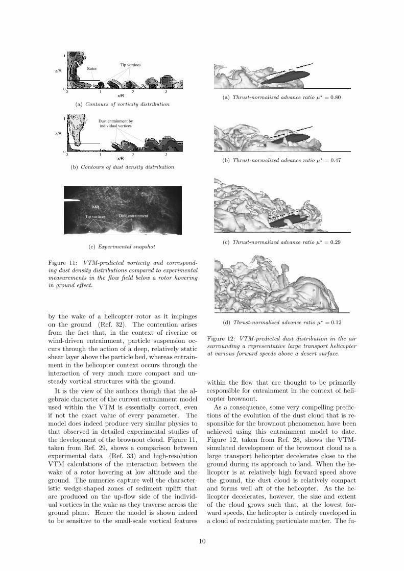
Figure 11: VTM-predicted vorticity and correspond-ing dust density distributions compared to experimentalmeasurements in the flow field below a rotor hoveringin ground effect.
by the wake of a helicopter rotor as it impingeson the ground (Ref. 32). The contention arisesfrom the fact that, in the context of riverine orwind-driven entrainment, particle suspension oc-curs through the action of a deep, relatively staticshear layer above the particle bed, whereas entrain-ment in the helicopter context occurs through theinteraction of very much more compact and un-steady vortical structures with the ground.
It is the view of the authors though that the al-gebraic character of the current entrainment modelused within the VTM is essentially correct, evenif not the exact value of every parameter. Themodel does indeed produce very similar physics tothat observed in detailed experimental studies ofthe development of the brownout cloud. Figure 11,taken from Ref. 29, shows a comparison betweenexperimental data (Ref. 33) and high-resolutionVTM calculations of the interaction between thewake of a rotor hovering at low altitude and theground. The numerics capture well the character-istic wedge-shaped zones of sediment uplift thatare produced on the up-flow side of the individ-ual vortices in the wake as they traverse across theground plane. Hence the model is shown indeedto be sensitive to the small-scale vortical features
(a) Thrust-normalized advance ratio µ? = 0.80
(b) Thrust-normalized advance ratio µ? = 0.47
(c) Thrust-normalized advance ratio µ? = 0.29
(d) Thrust-normalized advance ratio µ? = 0.12
Figure 12: VTM-predicted dust distribution in the airsurrounding a representative large transport helicopterat various forward speeds above a desert surface.
within the flow that are thought to be primarilyresponsible for entrainment in the context of heli-copter brownout.
As a consequence, some very compelling predic-tions of the evolution of the dust cloud that is re-sponsible for the brownout phenomenon have beenachieved using this entrainment model to date.Figure 12, taken from Ref. 28, shows the VTM-simulated development of the brownout cloud as alarge transport helicopter decelerates close to theground during its approach to land. When the he-licopter is at relatively high forward speed abovethe ground, the dust cloud is relatively compactand forms well aft of the helicopter. As the he-licopter decelerates, however, the size and extentof the cloud grows such that, at the lowest for-ward speeds, the helicopter is entirely enveloped ina cloud of recirculating particulate matter. The fu-
10

Figure 13: VTM-predicted vorticity and sand distribu-tions in the wake of a tidal turbine operating close tothe sea-bed.
ture challenge is to establish the key aerodynamicdesign parameters that influence most strongly thedevelopment of the dust cloud that is generated bythe helicopter (tip shape and blade twist appear sofar to be the strongest candidates, but the details ofthe trajectory that is followed to land would appearto be of overriding importance) and thus to informthe operation of such vehicles in desert conditionsas well as possibly their future design. One possi-bility, for instance, is that interchangeable bladesthat are especially adapted for operation in desertconditions might be developed.
The helicopter brownout problem has its ana-logue in a related problem that is experienced whensiting tidal turbines in shallow water. In this case,the wakes of the turbines can interact with the sea-bed to stir up sediment. This process has the po-tential to undermine the foundations of the turbineand also to increase water turbidity, possibly affect-ing marine life and water quality downstream of theturbines. Given the ecologically sensitive nature ofmany of the proposed sites for exploitation of tidalturbine technology, these are serious concerns — tothe extent that significant public controversy existsregarding the benefits of such technology versus itsperceived environmental impact.
VTM simulations show how, much as in the caseof helicopter-induced brownout, it is the effect ofthe individual vortices on the sediment bed ratherthan the gross properties of the wake that is respon-sible for the most significant transfer of materialfrom the ground into the fluid. Figure 13 shows aVTM-generated prediction of the wake and associ-ated sediment cloud that is generated downstreamof a three-bladed tidal turbine that is moored 1.1rotor radii above the ocean floor, in a water stream
that is 1/6 times the blade-tip velocity of the de-vice. Since tidal devices operate continuously, itcan be appreciated how even a moderate degree ofpersistent sediment uplift can, over time, result insignificant erosion to the sea-bed unless measuresare taken to ameliorate the ability of the wake todisturb any sediment layers that might be presentdownstream of the turbine. In this vein the tech-nological challenges are rather similar to those en-countered in the context of helicopter brownout.
Although understanding of the scouring problemis still in its infancy, high-resolution models such asthe VTM will be essential if reliable estimates of thebearing capacity of specific proposed sites for un-dersea turbines are to be provided. The hope is alsothat, through appropriate design in order to bal-ance the performance of individual turbines againsttheir environmental impact, tidal turbine technol-ogy will be able to play an important and publicly-accepted role in providing a significant proportionof the energy needs of Scotland’s future society.
Plume Ingestion
The ingestion of exhaust plumes into the rotors ofthe helicopter has both good and bad effect. Therotor can help to disperse the plume, but this pos-itive effect must be balanced against local heatingof the blades and an increase in the size of the ther-mal footprint of the helicopter. Predicting the dy-namics of the exhaust plume as it interacts withthe wake of the helicopter is thus an importantpractical issue. The dynamics of exhaust plumescan be modelled fairly straightforwardly within theVTM. The geometry of the plume can be definedby the extent of its associated vorticity field, and
Figure 14: VTM-predicted distortion of the exhaustplumes within the main rotor wake of a representativecoaxial helicopter in forward flight at an advance ra-tio µ=0.05 (light grey: rotor wake, dark grey: exhaustplume).
11

this field can be evolved through time using thevorticity transport equation (Eq. 1). To model theinfluence on the dynamics of the plume of the tem-perature differential between the exhaust flow andthe air surrounding the helicopter, an additionalscalar transport equation for the plume tempera-ture, of the form of Eq. 4, is evolved in parallelwith the VTM, and the appropriate baroclinic vor-ticity source term is appended to Eq. 1. Figure 14shows the results of a VTM calculation of the cou-pled dynamics of the rotor wake and the twin ex-haust plumes of a representative coaxial helicopterin forward flight at an advance ratio of 0.05. Thevery strong influence of the rotor downwash in re-directing the trajectory of the plume is clearly ev-ident in the figure. The effect of the individualvortices within the wake in mixing, dispersing anddisordering the flow within the plume, and thus inreducing the local temperature differential of theplume with respect to the ambient flow, can alsobe inferred from the diagram.
In the environmental context, the dispersal ofsmokestack plumes if they should pass through thewake of a nearby wind turbine is a key concern,given the possibility that turbines located too closeto any industrial plant might re-direct or otherwiseinterfere with the atmospheric pollutant load fromthe plant. The problem is two-fold. On a localscale, individual turbines might act to trap pollu-tion from a nearby smokestack, thus allowing thesecondary effect of particle fallout to produce a pos-sibly very unwelcome deposition of pollutants onthose properties located immediately downstreamof the turbine. On the meso-scale, a major con-cern is that wind farms located too close to indus-trial sites might act as reservoirs of contaminantsthrough their action in locally retarding the flow ofair within the atmosphere.
The problem of predicting the interaction be-tween a wind turbine and the plume emitted from asmokestack is very similar to that of predicting thedynamics of the exhaust plumes of rotorcraft, ex-cept that the problem involves longer ranges and isstrongly influenced by atmospheric turbulence andlarge-scale changes in the thermal properties of theplume and the atmosphere — for example the pres-ence or not of an inversion layer. Figure 15 showsthe results of a VTM simulation of a model prob-lem in which the interaction is modelled between awind turbine, operating at a tip-speed ratio of six,and the plume that is generated by a smokestacklocated four rotor radii upstream that is producinga jet of effluent with a mean speed at its source ofapproximately 1.5 times the local wind speed. Thesmokestack is offset so that the centreline of theundisturbed plume would pass through the lateraledge of the turbine disc. This model problem ismarginally unrealistic given the very close proxim-
Figure 15: VTM-predicted interaction between a windturbine and the plume from a smokestack located fourrotor radii upstream.
ity of the smokestack to the turbine, but all thepertinent physics are fully represented. The abilityof the VTM to act as an implicit large-eddy simula-tion is clearly apparent — indeed, a very convincingrepresentation of the transition of the flow withinthe chimney plume from laminar to turbulent isproduced. As with the helicopter exhaust plume,the interaction between the chimney plume and thewake of the turbine produces two effects. Firstly,the wake of the turbine acts to re-direct the tra-jectory of the plume — in this case the downwindconvection of a significant proportion of the ma-terial within the plume is retarded. Secondly, theindividual vortices in the wake act to mix and dis-perse the plume. The influence of the turbine wakein disordering and dispersing the chimney plumeis particularly marked further downstream as thewake of the turbine succumbs to the inherent in-stability of its constituent vortex filaments. Theresults presented here hint at how a model, devel-oped in the context of helicopter exhaust plumeprediction, might be used effectively to provide in-formation that is of use to environmental agenciesand industrial planners in informing their strategiesfor future land-use. The utility of this particular in-carnation of the VTM is expected to follow in thewake of steadily increasing environmental pressuresto avoid the expansion of wind turbine sites intopristine natural estate. Indeed, the drive towardseffective and concentrated use of appropriate landwill increasingly be directed towards the locationof small, localised turbine farms on recycled brown-field sites, possibly in the midst of pre-establishedindustrial developments.
12

Conclusion
Several technical issues that arise in the field ofrenewable energy research have direct analogues inthe field of helicopter engineering. This paper illus-trates several areas where insights obtained fromusing the Vorticity Transport Model in the heli-copter field have had, or are having, direct applica-tion in the area of wind and tidal turbine research.
A variety of studies have contributed to faith inthe VTM when applied to the analysis of the loadson helicopter rotor blades. Comparisons of VTMpredictions against the data set that was gener-ated during the HART-II experimental campaignsuggest that such computational methods are ap-proaching a level of fidelity where they are able topredict the secondary characteristics of the rotor,such as the pattern of acoustic radiation that it gen-erates, with reasonable confidence. Extension intothe wind turbine field has exposed the VTM to anew set of aerodynamic challenges, however. Com-parisons of VTM predictions against wind tunnelmeasurements of the blade-loads on a wind tur-bine, conducted as part of the NREL Phase VIcampaign, reveal, for instance, that careful atten-tion has to be paid to the development of radialflows along the length of the blade, and the subse-quent effect that this has on the onset of stall onthe turbine. Blade stall is an important issue inhelicopter operation as well, since it places limitson the flight envelope of the vehicle. The influ-ence of radial flow on the development of stall onthe blades has not received the same attention inthe helicopter community as in the wind turbinecommunity, however. Nevertheless, as the advanceratio of operational helicopter systems continues toincrease, there may be significant opportunity fortechnology transfer between the two fields.
The aerodynamic interactions that occur withina wind farm can cause the constituent turbines togenerate a lower power output than would be pos-sible if each of the turbines were operated in iso-lation. Tightening of the constraints on the sit-ing of wind farms is likely to increase the scaleof this problem in the future. VTM simulationsshow that the momentum deficit at a turbine op-erating within the wake developed by the rotor ofa second turbine can limit substantially its meanpower output. Also, wake induced unsteadiness inthe aerodynamic loading on the rotor blades of thedownstream turbine has considerable implicationsfor the fatigue life of the blade structure and ro-tor hub, particularly in certain configurations andwind conditions. Detailed calculations show thatthe aerodynamic interaction between wind turbinesis governed by the essentially inviscid physics ofwake instability, rather than by viscous wake dissi-pation as is assumed in many of the current models
used by the wind turbine community. This prob-lem bears striking similarities to that associatedwith the interaction between the main and tail ro-tors of a conventional helicopter. This interactioncan have a strong negative influence on the flightmechanics of the helicopter. Significant unsteadi-ness in the tail rotor loading is encountered un-der certain flight conditions, but the character ofthe unsteadiness can depend on the direction ofrotation of the tail rotor. VTM simulations of theaerodynamic interaction between the main and tailrotors of a helicopter show distinct differences inthe behaviour of the system in left and right cross-wind flight that are consistent with flight experi-ence — the greatest fluctuations in loading or con-trol input are required in left sideways flight (fora counter-clockwise rotating rotor) and are gener-ally more extreme for a system with tail rotor ro-tating top-forward than top-aft. Although not yetfully understood, the observed behaviour, in thehelicopter context, appears to originate in a globalunsteadiness in the flow field that arises in the pro-cess whereby the tail rotor wake merges with thewake of the main rotor.
A particular concern to helicopter operators indesert or dusty conditions is the possibility of en-trainment of dust from the ground into the air whenthe vehicle is operated close to the ground. Thisprocess can cause large clouds of dust to form inthe air surrounding the helicopter, and the possi-bility exists, under certain operational conditions,that these clouds might obscure the pilot’s view,particularly while landing or taking off. A cou-pled VTM – sand transport model has been usedto analyze the differences in the geometry and ex-tent of the dust clouds that are produced by dif-ferent helicopter configurations as they decelerateto land. This study has shown that the location ofthe ground vortex and the size of any regions of re-circulatory flow, should they exist, play a primaryrole in governing the extent of the dust cloud thatis created by the helicopter. This problem is verysimilar to that experienced when siting tidal tur-bines in shallow water. In this case, the wakes ofthe turbines can interact with the sea-bed to stirup sediment. This process has the potential to un-dermine the foundations of the turbine and also toincrease water turbidity, possibly affecting marinelife and water quality downstream of the turbines.VTM simulations show how, much as in the case ofhelicopter-induced brownout, it is the effect of theindividual vortices on the sediment bed rather thanthe gross properties of the wake that is responsiblefor the most significant transfer of material fromthe ground into the fluid. The perceived environ-mental impact of large-scale marine turbine tech-nology is a particularly important issue in its publicacceptance as a significant contributor to future en-
13

ergy requirements. The observed sensitivity of thesize and shape of the helicopter brownout cloud todetails of the rotor configuration suggests that theenvironmental impact of tidal turbines may also beameliorated by careful design of their rotors.
The ingestion of exhaust plumes into the rotorsof the helicopter has both good and bad effect. Therotor can help to disperse the plume, but this posi-tive effect must be balanced against local heating ofthe blades and an increase in the size of the thermalfootprint of the helicopter. Predicting the disper-sal of the thermal plume within the wake of thehelicopter is thus an important issue. In the en-vironmental context, the dispersal of smokestackplumes if they should pass through the wake of anearby wind turbine is a key concern, given thepossibility that turbines located too close to anyindustrial plant might re-direct or otherwise inter-fere with the atmospheric pollutant load from theplant. The problem of predicting this interaction isvery similar to that of predicting the dynamics ofthe exhaust plumes of rotorcraft, except that theproblem involves longer ranges and is strongly in-fluenced by atmospheric turbulence and large-scalechanges in the thermal properties of the plume andthe atmosphere — for example the presence or notof an inversion layer. VTM simulations are pre-sented that show how a model developed in thecontext of helicopter exhaust plume prediction canbe used effectively to provide information that is ofuse to environmental agencies and industrial plan-ners in informing their strategies for future landuse.
The perceived need to reduce mankind’s impacton his environment, and in particular on the globalclimate, is driving a very strong movement towardsa future society in which a significant proportion ofits energy needs will be extracted from the windsand the tides of the planet. This paper shows sev-eral examples of how cross-disciplinary informationtransfer between the rotorcraft field and the renew-able energy community is helping to develop thetechnologies that will be required by this future so-ciety, as well as helping to understand the environ-mental issues that might need to be faced as thesetechnologies become more prevalent.
References
1de Noord, M., Beurskens, L.W.M., and de Vries,H.J., “Potentials and Costs for Renewable Electric-ity Generation — a Data Overview,” Energy Re-search Centre of the Netherlands Report ECN-C-03-006, March, 2006.
2RSPB Scotland, WWF Scotland and FOE Scot-land, “The Power of Scotland: Cutting Car-bon with Scotland’s Renewable Energy,” February,2006.
3Salmond, A, “Small Country Thinks Big,” Scot-tish Renewables Review, No. 32, November 2006.
4Brown, R.E., “Rotor Wake Modeling for FlightDynamic Simulation of Helicopters,” AIAA Jour-nal, Vol. 38, No. 1, 2000, pp. 57–63.
5Brown, R.E., and Line, A.J., “Efficient High-Resolution Wake Modeling Using the VorticityTransport Equation,” AIAA Journal, Vol. 43,No. 7, 2005, pp. 1434–1443.
6Toro, E. F., “A Weighted Average Flux Methodfor Hyperbolic Conservation Laws,” Proceedings ofthe Royal Society of London, Series A: Mathemati-cal and Physical Sciences, Vol. 423, No. 1865, 1989,pp. 401–418.
7Kenyon, A.R., and Brown, R.E., “Wake Dy-namics and Rotor-Fuselage Aerodynamic Interac-tions,” Journal of the American Helicopter Society,Vol. 54, No. 1, 2009, pp. 012003-1–18.
8Whitehouse, G.R., and Brown, R.E., “Modelingthe Mutual Distortions of Interacting Helicopterand Aircraft Wakes,” Journal of Aircraft, Vol. 40,No. 3, 2003, pp. 440–449.
9Green, R.B., Gillies, E.A., and Brown, R.E.,“The Flow Field around a Rotor in Axial Descent,”Journal of Fluid Mechanics, Vol. 543, No. 1, 2005,pp. 237–261.
10Ahlin, G.A., and Brown, R.E., “Wake Structureand Kinematics in the Vortex Ring State,” Journalof the American Helicopter Society, Vol. 54, No. 3,2009, pp. 032003-1–18.
11Kim, H.W., and Brown, R.E., “Coaxial RotorPerformance and Wake Dynamics in Steady andManoeuvring Flight,” 62nd American HelicopterSociety Annual Forum, Phoenix, Arizona, USA, 9–11 May 2006.
12Kim, H.W., Kenyon, A.R., Duraisamy, K. andBrown, R.E., “Interactional Aerodynamics andAcoustics of a Hingeless Coaxial Helicopter with anAuxiliary Propeller in Forward Flight,” Aeronauti-cal Journal, Vol. 113, No. 1140, 2009, pp. 65–78.
13Kelly, M.E., and Brown, R.E., “The Effect ofBlade Aerodynamic Modelling on the Predictionof High-Frequency Rotor Airloads,” 65th Ameri-can Helicopter Society Annual Forum, Grapevine,Texas, USA, 27–29 May, 2009.
14Kelly, M.E., and Brown, R.E., “The Effect ofBlade Aerodynamic Modelling on the Predictionof the Blade airloads and the Acoustic Signature ofthe HART II Rotor,” 35th European Rotorcraft Fo-rum, Hamburg, Germany, 22–25 September, 2009.
14

15van der Wall, B. G., Junker, B., Burley,C., Brooks, T., Yu, Y., Tung, C., Raffel, M.,Richard, H., Wagner, W., Mercker, E., Pengel,K., Holthusen, H., Beaumier, P., and Delrieux, Y.,“The HART II test in the LLF of the DNW — aMajor Step towards Rotor Wake Understanding,”28th European Rotorcraft Forum, Bristol, Eng-land, 17–20 September, 2002.16Scheurich, F., Fletcher, T.M., and Brown, R.E.,
“Simulating the Aerodynamic Performance andWake Dynamics of a Vertical-Axis Wind Turbine,”Wind Energy, in press.17Morris, J., “Sikorsky Calls X2 Shape of the Fu-
ture,” Aviation Week, 25 February, 2008.18Hand, M.M., Simms, D.A., Fingersh, L.J.,
Jager, D.W., Cotrell, J.R., Schreck, S., and Lar-wood, S.M., “Unsteady Aerodynamics ExperimentPhase VI: Wind Tunnel Test Configurations andAvailable Data Campaigns,” National RenewableEnergy Laboratory TP-500-29955, 2001.19Breton, S., Coton, F.N., and Moe, G., “A Study
on Rotational Effects and Different Stall DelayModels Using a Prescribed Wake Vortex Schemeand NREL Phase VI Experiment Data,” Wind En-ergy, Vol. 11, No. 5, 2008, pp. 459–482.20Fletcher, T.M, Brown, R.E., Kim, D.H., and
Kwon, O.J., “Comparative Simulations of WindTurbine Aerodynamics using Vorticity Transportand RANS Models,” Wind Energy, in press.21Sørensen, N.N., Michelsen, J.A., and Schreck,
S., “Navier-Stokes Predictions of NREL Phase VIRotor in the NASA Ames 80 ft×120 ft Wind Tun-nel,” Wind Energy Vol. 5, No. 23, 2002, pp. 151–169.22Fletcher, T.M, Brown, R.E., Kim, D.H., and
Kwon, O.J., “Predicting Wind Turbine BladeLoads using Vorticity Transport and RANSMethodologies,” European Wind Energy Confer-ence 2009, Marseille, France, 16–19 March, 2009.23Somers, D.M., “Design and Experimental Re-
sults for the S809 Airfoil,” Airfoils, Inc., State Col-lege, Pennsylvania, USA, 1989.24Corrigan, J. J., and Schillings, J. J., “Empirical
Model for Stall Delay due to Rotation,” AmericanHelicopter Society Aeromechanics Specialists Con-ference, San Francisco, California, USA, January1994.
25Voutsinas, S.G., Rados, K.G., and Zervos, A.,“On the Analysis of Wake Effects in Wind Farms,”Wind Engineering, Vol. 14, No. 4, 1990, pp. 204–219.
26Fletcher, T.M, and Brown, R.E., “Simulat-ing Wind Turbine Interactions using the VorticityTransport Model,” 28th ASME Wind Energy Sym-posium, Orlando, Florida, USA, January, 2009.
27Fletcher, T.M, and Brown, R.E., “Main Ro-tor – Tail Rotor Interaction and its Implicationsfor Helicopter Directional Control,” Journal of theAmerican Helicopter Society, Vol. 53, No. 2, 2008,pp. 125–138.
28Phillips, C., and Brown, R.E., “Eulerian Sim-ulation of the Fluid Dynamics of HelicopterBrownout,” Journal of Aircraft, Vol. 46, No. 4,2009, pp. 1416–1429.
29Phillips, C., Kim, H.W., and Brown, R.E., “TheEffect of Rotor Design on the Fluid Dynamicsof Helicopter Brownout,” 35th European Rotor-craft Forum, Hamburg, Germany, 22–25 Septem-ber, 2009.
30Lee, T.E., Leishman, J.G., and Ramasamy, M.,“Fluid Dynamics of Interacting Blade Tip Vor-tices With a Ground Plane,” 64th American He-licopter Society Annual Forum, Montreal, Canada,29 April–1 May, 2008.
31Whitehouse, G.R., Wachspress, D.A., Quack-enbush, T.R., and Keller, J.D., “ExploringAerodynamic Methods for Mitigating Brownout,”65th American Helicopter Society Annual Forum,Grapevine, Texas, USA, 27–29 May, 2009.
32Johnson, B., Leishman, J.G., and Sydney,A., “Investigation of Sediment Entrainment inBrownout Using High-Speed Particle Image Ve-locimetry,” 65th American Helicopter Society An-nual Forum, Grapevine, Texas, USA, 27–29 May,2009.
33Nathan, N.D., and Green, R.B., “Measurementsof a Rotor Flow in Ground Effect and Visualisa-tion of the Brown-out Phenomonon,” 64th Amer-ican Helicopter Society Annual Forum, Montreal,Canada, 29 April–1 May, 2008.
15


![Alkoholabh ngigkeit Scheurich 16122014insNetz.ppt ... · Title (Microsoft PowerPoint - Alkoholabh ngigkeit_Scheurich_16122014insNetz.ppt [Kompatibilit tsmodus]) Author =° dæ Created](https://static.fdocuments.in/doc/165x107/5cb2e9ac88c99342708c19c2/alkoholabh-ngigkeit-scheurich-title-microsoft-powerpoint-alkoholabh-ngigkeitscheurich.jpg)