
Keiser 300 / Air 300 Parts and Maintenance Manualmanuals.keiser.com/downloads/air300/A300...
46
Keiser 300 / Air 300 Parts and Maintenance Manual
Transcript of Keiser 300 / Air 300 Parts and Maintenance Manualmanuals.keiser.com/downloads/air300/A300...
Keiser 300 / Air 300
Parts andMaintenance
Manual

2
Table of Contents
Introduction – How it Works 4Preventive Maintenance 5Troubleshooting 6Air Hoses and Fittings 7Filter 9Valves 10Cylinders 14Mufflers 17Fasteners 18Arm Locks 19Bearings 21Hand Grips 23Upholstery – Decals 25Parts Identification 26
SAFETY CAUTIONS:We’ve put a number of safety cautions in this book. We use the word CAUTION to tellyou about things that could cause bodily injury to persons on or around the equipment ifyou were to ignore the warning.
MACHINE DAMAGE NOTICE:Also, in this book you will find the word NOTICE. This tells you about things thatcould hurt the machine if you were to ignore these warnings.

3
4
K300 – HOW IT WORKS
Two basic systems are used to operate the KEISER 300 series exercise machines.
On machines that exercise the muscle groups of the upper body, the resistance is
controlled by means of foot pedals mounted on the base of the machine. Thumb buttons
in the handles operates machines for lower body muscle groups.
When the quick-disconnect is plugged into the air system, compressed air flows
into the machine. In all but the Seated Chest Press, Lateral Shoulder Raise, Military
Press, Tricep, and Seated Butterfly, the air flows through the filter to the increase valve
(in the machine above, the filter is in a different location, but its function is identical).
The filter removes moisture and particles, which may be harmful to the cylinders.
When the increase valve is depressed, the air flows into the cylinders, tanks, and
gauge through one or more manifolds. Moving the exercise arm through its range drives
the piston in the cylinder against the air pressure. The air, in effect, pushes back against
the piston, creating mechanical resistance. When the increase valve is held down, the
resistance becomes greater until the maximum cylinder pressure is reached.
Depressing the decrease valve opens the system to the atmosphere, allowing the
cylinder air to escape. The resistance decreases as the pressure is reduced.
The gauge is calibrated to show the maximum amount of resistance developed by
the machine. The gauge reading is correct when the exercise arms are against their stops.
The gauge needle will move during the exercise motion. This is characteristic of the
system and does not indicate a malfunction.

5

6

7
PROBLEM: Pressure changes without valves being actuated.Service the Valves (see pg. 9)
AIR HOSES AND FITTINGS
All K300 machines use polyethylene tubing and “Compress-align” fittings to connect the
various pneumatic components within the machine.
If an air leak is suspected, first listen closely to the air hose connections. Leaks will
make a hissing noise. Very slight leaks may not be loud enough to hear. These may be
detected by dabbing soapy water on the suspected leak. Escaping air will make bubbles.
If the leak is at a fitting, first tighten the nut about one-quarter (1/4) of a turn. Test the
connection again. If the fitting still leaks, the nut must be replaced. In most cases the air
hose should be long enough to allow this; if not, order a new air hose from KEISER.
To install a new nut:
TOOLS REQUIRED: adjustable wrench and a sharp knife
1. Cut the tubing as close as possible to the nut. The cut must be clean and square.
2. Slip a new nut over the tubing.
3. Insert the tubing into the fitting all the way to the shoulder inside the fitting (see the
cutaway illustration).
4. Hold the tubing in the fitting and slide the nut down onto the fitting. Tighten the nut
as tight as possible with the fingers, then another one full turn with a wrench.
If reinstalling an air hose, tighten the nut finger-tight, plus one-quarter (1/4) turn. This
will allow the nut to be used three more times before it must be replaced.

8
QUICK – DISCONNECT
The feed hose is connected to the quick-disconnect and the machine with compress-align
fittings. If the feed hose must be repaired or replaced, follow this procedure:
1. To replace hose, unscrew the compress-align nuts on both ends and remove the hose
(new hoses and compress-align nuts are available from KEISER).
2. To shorten the hose, unscrew chrome compress-align nut from the quick-disconnect
and cut the hose to the desired length. Slide a new chrome nut (an extra one is
supplied with each machine) onto hose.
3. To tighten the compress-align nuts, slide the hose all the way into the fitting and
thread the nut on hand-tight. Tighten the brass nut one full turn more with a ½ in.
open-end wrench. The chrome nut may require more turns, due to the chrome on the
threads. Make sure the hose is held securely in place at both fittings.

9
FILTER
The air filter keeps moisture and dirt out of the cylinders and other components. The
filter bowl must be kept free of moisture. Filter bowls that fill quickly with water
indicate a problem with the air dryer. If your air system does not include a dryer, the
filters on all machines must be checked and/or drained daily.
This is best done by pressing on the drain valve until all moisture blows free. The
moisture can be caught in a towel. CAUTION : IF THE FILTER BOWL IS CRACKED,
IT MUST BE REPLACED IMMEDIATELY. NOTICE: IF FILTER BOWL IS
CRACKED, AN AIR LEAK COULD RUN THE COMPRESSOR CONTINUOUSLY,
PUTTING EXCESSIVE WEAR ON THE COMPRESSOR.
The internal parts of the filter and the bowl can be cleaned. Always decrease resistance
to zero before starting service or repair on any K300 machine.
To service:
Unplug the quick-disconnect and unscrew the bowl and element holder from the housing.
Clean all parts with dish soap and water. Do not use solvent or other strong chemicals on
any part of the filter. Allow the element to dry thoroughly. Lightly coat the bowl seal
with SAE 30 wt. Oil and reassemble. Leaky drain valves can be replaced with a bicycle
tire tube valve available at most hardware stores.

10
VALVES
The valves in the pedals or handles can be removed for service or repair. Always unplug
the quick-disconnect from the air system and decrease the resistance to zero before
working on the valves. The following groups of machines state the type of valve and its
maintenance procedures.
LEG EXTENSION, LEG CURL, SQUAT, HIP ABDUCTOR, LEG PRESS,STANDING HIP, ABDOMINAL, LOWER BACK, AND SEATED CALF
1. Trace the hoses on the valves to their connections on the filter or manifold. An
increase valve is connected to two hoses, one from the filter and one to the manifold.
Decrease valves are connected to one hose from the manifold and one from the
exhaust muffler. Mark the hoses with tape so they can be reassembled properly, then
disconnect.
2. Decrease the resistance to zero. Remove the grip end cap from the handle and pull
the valve out to a point where the hose can be cut about ½ inch from the bottom of the
valve housing. Cut the hoses clean and square, and cut the small remaining piece off
the barbed fittings. NOTICE: DO NOT DAMAGE BARBS. DAMAGED BARBS
ARE AREAS FOR POSSIBLE LEAKS.

11
3. Rest the valve housing on the open jaws of a vise and drive out the spring pin with a
hammer and 3/16-drift punch (see illustration below). When the punch is removed,
the spool can be removed as shown.
4. Remove the O-rings off the spool. CAUTION : DO NOT CUT SPOOL! CUTS IN A
SPOOL ARE AREAS FOR POSSIBLE AIR LEAKS. Wipe the spool completely
dry with a clean dry cloth and inspect it carefully for signs of wear or deterioration.
Lightly coat the narrow part of the spool with silicon lubricant and slip on three new
O-rings.
5. Clean the inside passages of the valve housing with solvent and compressed air. Do
not use any kind of tool inside the housing. Inspect the bore for scratches or wear of
any kind. The housing should be replaced if there are any imperfections in the bore.
6. Assembly is the opposite of disassembly. Tap the spring pin into the spool until it is
just flush with the outside of the housing.
7. For increase valves, push the air hose from the filter over the barb on the high-
pressure side of the valve (see illustration), and the air hose to the manifold on the
low-pressure side. Push the hose all the way up to the flange. For decrease valves,
the air hose from the manifold is connected to the high pressure side, and the air hose
from the muffler is connected to the low pressure side.
12
8. Replace the valve in the machine and remount the end cap on the end of the handle (if
you have any questions on the preceding steps, please contact our service
department).
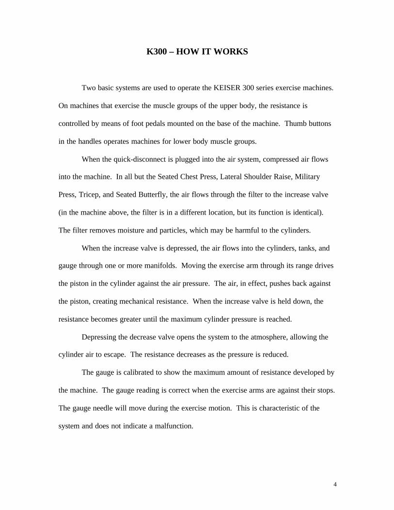
SEATED CHEST PRESS, LATERAL SHOULDER RAISE, MILITARY PRESS,TRICEP, AND SEATED BUTTERFLY
NOTE: Machines shipped before October, 1985 have nuts and bolts holding the valves in
place. Later machines use only flat head screws for easier access to the valves. The
procedure described here applies specifically to the older machines but the same general
procedure also applies to the new machines.
TOOLS REQUIRED: 5/16, 3/8, 7/16 open-end wrenches, screwdriver
1. Tilt the machine back and lay it down so that the pedal assembly is easily accessible.
NOTICE: REST THE MACHINE ON FRAME MEMBERS ONLY. TO PROTECT
AIR HOSES AND FITTINGS.

13
2. Loosen the adjusting screw behind the pedal. Hold the nuts on top of the valve with a
3/8 open-end wrench and remove the screw with a 5/16 wrench or socket. The valve
can now be lifted off the link, and the valve cartridge removed for service or
replacement. On machines shipped after October, 1985, a standard screwdriver is
used to remove the valve mounting screws.
3. Assembly is the opposite of removal. Use the adjusting screw to make the pedal even
and parallel to the ground. Lock the adjusting screw in place with “Loctite 292”.
VALVE SERVICING
TOOLS REQUIRED:1/2 inch wrench or socket, rag, DOW CORNING 111.
1. Remove the brass valve cartridge from the aluminum housing. Make sure that the O-
ring indicated does not remain in the housing. If it does, use the spring to remove it.
2. Push the spool out of the lining. Wipe all parts clean with a soft dry, lint-free cloth.
Do not use alcohol or petroleum-based cleaning solution. Check all parts for cracks
or excessive wear. Replace entire unit if worn or damaged.
3. Wipe a thin film of DOW CORNING 111 compound on the valve and bore.
Reassemble the valve cartridge.
4. Reinstall the valve cartridge. NOTICE: DO NOT OVER TIGHTEN.

14
CYLINDERS
Three types of cylinders are used on K300 series machines:2 ½ “ x 7” = Part #:11-53172 ½ “ x 12”= Part #:13-5316
4” x 12”= Part #:15-5314
Maintenance procedures are the same for all three types of cylinders.
TOOLS REQUIRED: adjustable wrench, 5/16 or ¼ inch allen wrench and an oil can.
REMOVAL:
1. Unplug the quick-disconnect from the air system and reduce the resistance to zero.
2. Remove the air hose from the cylinder. It is best to remove one cylinder at a time. If
both cylinders must be removed, mark the cylinders and air lines to avoid mistakes in
re-assembly.
3. Remove the nuts and bolts holding the cylinder and clevis. Check the bearings in the
tang end of the cylinder and the lever arm. If they are loose or worn, they must be
replaced.

15
TO REPLACE THE CYLINDER:
1. Put a drop of oil on the bearings and remount the cylinder. Tighten all nuts securely.
2. Reattach the air hose. Tighten the nut finger-tight, plus ¼ turn. Plug in the quick-
disconnect and check for air leaks. If the fitting leaks, tighten the nut another ¼ turn.
If the leak persists, replace the nut.
CYLINDER SERVICING
NOTICE: IT IS VERY IMPORTANT THAT THE CYLINDER ROD AND BORE
ARE NOT SCRATCHED OR DAMAGED IN ANY WAY. DAMAGED CYLINDER
RODS AND BORES ARE AREAS FOR POSSIBLE AIR LEAKS.
TOOLS REQUIRED: 11/16 wrench or socket, internal snap ring pliers, rag and Mt-55
light grease
1. Using the 11/16 wrench, carefully remove the muffler from the end housing of the
cylinder.
2. Clamp the tang of the cylinder in a vise or have someone hold the cylinder. If the
ends of the snap ring are not visible, the end housing must be rotated until both ends
are visible through the cut-out.

16
3. Pull the rod out 2/3 to ¾ of the way. Squeeze the snap ring with snap ring pliers and
pull on the rod to “tap” the end housing out of the cylinder (see illustration).
4. Wipe out the bore of the cylinder with a lint-free rag and inspect for scratches or
uneven wear. If found, contact KEISER for a replacement.
5. Clean the piston and inspect for wear or damage. If any metal particles are found on
the piston or inside the cylinder contact KEISER for a replacement.
6. Clean wear the strip grooves and apply a moderate coat of “Hydrotex MT-55” light
grease (available from KEISER) to hold wear strips in place during assembly.
Lightly coat the bore, cup seal, piston and wear strips with MT-55 light grease.
NOTICE: OPEN END OF CUP SEAL MUST FACE AWAY FROM THE
CYLINDER ROD. Carefully re-assemble the cylinder.
7. Apply a very light coat of lube to the muffler threads and reinstall snug, but not tight.
8. Operate piston by hand through its stroke. There should be no stickiness or metal-to-
metal contact.
9. Wipe the cylinder rods clean and coat them lightly with clean, SAE 30 wt. Motor oil.
ADJUSTMENT
Cylinders are factory adjusted and need not be readjusted unless the cylinder or clevis
becomes loose or is replaced. While each machine is checked differently, cylinder
adjustments are basically the same. TOOLS REQUIRED: 2 large adjustable wrenches

17
1. Hold the clevis in position with a wrench as shown (1) and loosen the lock nut.
NOTICE: LOOSENING THE LOCK NUT WITHOUT HOLDING THE CLEVIS CAN
DAMGE THE BUSHINGS, CLEVIS AND THE CYLINDER ROD.
2. Adjust the rod length (2) as required.
3. Hold the clevis and tighten the lock nut. Watch the rod to make sure it does not turn
while tightening the nut.
MUFFLERS
The mufflers on the rod ends of the cylinders should be replaced at any time cylinder
problems are suspected. Removing the muffler and moving the exercise arm through its
range will determine if the muffler is clogged. A clogged muffler will make the motion
spongy or rough. When replacing a muffler, coat the threads with oil, silicon lubricant,
or “WD-40”, and reinstall snug but not tight. Mufflers on decrease pedal valves should
be checked or replaced if the resistance decreases slowly or incompletely.
18
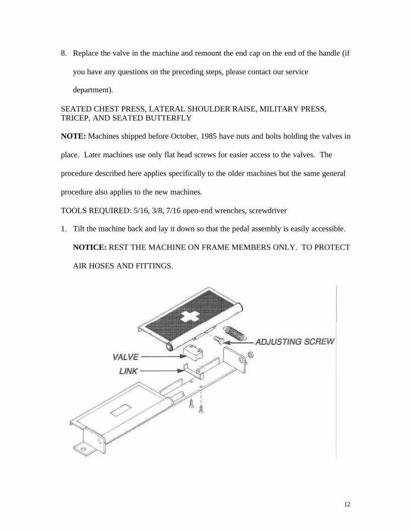
FASTENERS
NUTS AND BOLTS
Tightness of nuts and bolts should be checked monthly. Main frame bolts are generally
held in place through an internal mounting tube (see illustration). These bolts should be
tight (35-40 ft.-lbs.). Other bolts should not be tightened any more than necessary to
keep them from turning freely. NOTICE: OVER TIGHTENING BOLTS, WHICH GO
THROUGH THE MIDDLE OF TUBES, WILL CRUSH THE TUBE AND DESTROY
THE CHROME FINISH.
TOOLS REQUIRED: drift punch and a hammer
Spring pins are used to hold a shaft in place or to fasten a collar to a shaft. With the
exception of the arm lock shafts, spring pins are always shorter than the diameter of the
shaft. The procedures for removal and replacement of spring pins are as follows:
SPRING PIN REMOVAL:
1. Look at the exploded view of the machine in the parts section and find the size of the
pin.
2. Using the proper size drift punch, tap the pin into the shaft until the pin is completely
out of the bracket or collar.
19
3. Remove the shaft from the bracket or the collar from the shaft, and tap the spring pin
through and out of the shaft. NOTICE: ALWAYS REMOVE THE PIN FROM THE
SHAFT IMMEDIATELY. ACCIDENTAL INSTALLATION OF A SECOND PIN
WILL DAMAGE THE MACHINE.
SPRING PIN REPLACEMENT:
1. Check the hole in the shaft to make sure the old pin has been removed. Assemble the
shaft in the bracket or grip collar on the shaft.
2. Tap the new spring pin into the bracket or collar until the end of the pin is flush with
the outside. Be careful not to damage chrome.
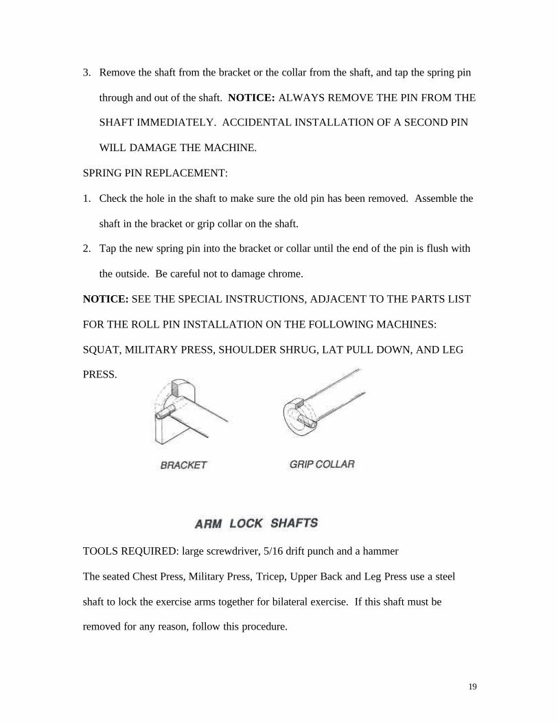
NOTICE: SEE THE SPECIAL INSTRUCTIONS, ADJACENT TO THE PARTS LIST
FOR THE ROLL PIN INSTALLATION ON THE FOLLOWING MACHINES:
SQUAT, MILITARY PRESS, SHOULDER SHRUG, LAT PULL DOWN, AND LEG
PRESS.
TOOLS REQUIRED: large screwdriver, 5/16 drift punch and a hammer
The seated Chest Press, Military Press, Tricep, Upper Back and Leg Press use a steel
shaft to lock the exercise arms together for bilateral exercise. If this shaft must be
removed for any reason, follow this procedure.

20
REMOVING THE SHAFT:
1. Pry off the plastic cap covering the locking sleeve and spring pin. On the Seated
Chest Press and Upper Back, this is the middle of the three square tubes. On the
Military Press and Tricep, it is the outside tube. This cap must be replaced with a new
part. NOTICE: BE CAREFUL NOT TO SCRATCH THE CHROME.
2. Pry off the white plastic locking sleeve with a screwdriver.
3. Using a 5/16 drift punch, drive the spring through and out of the shaft. The shaft and
spring pin can now be removed.
REPLACING THE SHAFT:
4. Put the shaft back into holes in the exercise arms.
5. Drive the spring pin through the shaft until it is just flush with the side of the shaft
facing you.
6. Push the locking sleeve over the shaft.
7. Using a rubber mallet or block of wood and hammer, drive a new plastic cap into the
end of the square tube.
21
BEARINGS
The ½, 5/8, and 1 inch flange bearings must be lubricated every 3 months. Using SAE 30
wt. Motor oil, put one drop on the exposed portion of each bearing. Move the machine
through its range to work the oil in, then wipe the area around it free of exposed oil.
T-88 REMOVAL AND REPLACEMENT
CAUTION: THIS PROCEDURE REQUIRES A HIGH QUALITY, HARDENED ¼
INCH ALLEN WRENCH. USE OF INFERIOR TOOLS CAN DAMGE THE
MACHINE AND MAY CAUSE INJURY TO HANDS OR ARMS IF WRENCH
STRIPS OUT.
T-88 BEARING REMOVAL:
1. Disconnect linkages from exercise arms.
2. Loosen silver screw.
CAUTION: SILVER SCREW SHOULD BE EXTREMELY TIGHT (50 FT. – LBS.).
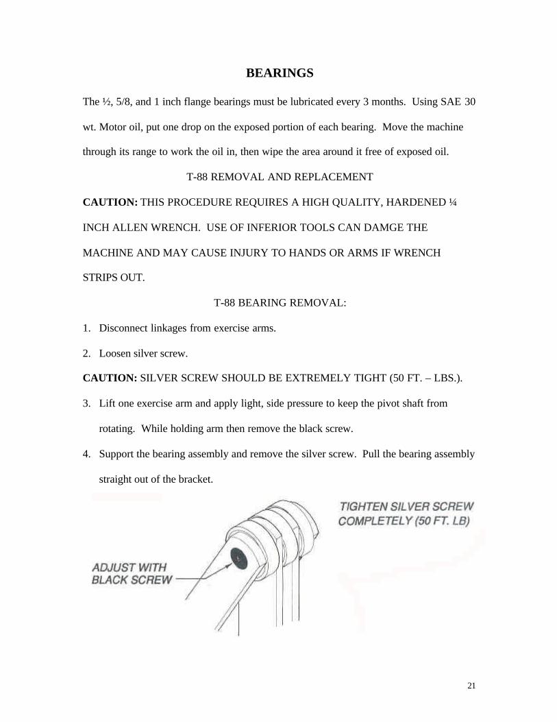
3. Lift one exercise arm and apply light, side pressure to keep the pivot shaft from
rotating. While holding arm then remove the black screw.
4. Support the bearing assembly and remove the silver screw. Pull the bearing assembly
straight out of the bracket.

22
NOTICE: Protect the shaft and bearings from damage and foreign matter.
T-88 BEARING REPLACEMENT:
5. Slide the bearing assembly in place and support it with both screws.
6. Tighten the silver screw (hold shaft as in step # 3) to 50 ft.-lbs.
7. Adjust the black screw as described in the adjustment.
T-88 BEARING ADJUSTMENT
TOOLS REQUIRED: ¼ allen wrench
These bearing assemblies are located between the exercise arms and underneath the
bearing cover of the Leg Extension, Leg Curl and Arm Curl, and support the pivot for the
main arm assemblies. The assembly consists of three T-88 bearings, which are
sandwiched between the two arms and the two brackets. In between these bearings lie a
pivot shaft, and one silver and one black flat head hex socket (FHHS) screw. These
bearings are permanently lubricated at KEISER and do not need any other lubrication.
The T-88 bearing assembly should be checked weekly, and adjusted slightly tighter if the
arms have excessive side-play. To adjust the assembly use a ¼ inch allen wrench to
make sure that the silver FHHS screw is tight. Lift the arm closest to the black FHHS
screw and notice the amount of side-play that exists between the arm and the two T-88
bearings on either side. Using the ¼ inch allen wrench, tighten the black FHHS screw
very slowly at the same time you check the side-play of the arm. When there is no
visible side-play, the bearing assembly is adjusted properly. Check to make sure both
arms move freely to prevent over-tightening. With a clean cloth, wipe any exposed
grease from around each T-88 bearing.

23
HAND GRIPS
TOOLS REQUIRED: Clean throwaway cloth, rubbing alcohol, 5/64” allen wrench, and
LPS cleaner/degreaser (available at auto parts and hardware stores).
THUMB BUTTON GRIP
CAUTION: USE KEISER GRIPS ON KEISER MACHINES ONLY! USING GRIPS
FROM ANY OTHER PRODUCTS MAY CAUSE SERIOUS INJURY.
1. Read all the instructions first before beginning any steps.
2. Leaving the thumb button in place, cut the old style grips from the handles. Remove
“all” tape and adhesive from the handles using LPS – cleaner/degreaser or rubbing
alcohol (alcohol will require extra work to remove all traces of adhesive). NOTICE:
DO NOT GET ALCOHOL OR DEGREASER IN THE THUMB BUTTON.
CAUTION: FAILURE TO REMOVE ALL ADHESIVE FROM THE HANDLES
MAY CAUSE THE GRIP SLEEVE TO SLIP, CAUSING BODILY INJURY TO
PEROSNS ON OR AROUND THE EQUIPMENT.
3. Apply alcohol inside the grip sleeve until the grip sleeve is completely coated.
4. Slip on the grip collar then slip the grip sleeve over the handle shaft until the grip
sleeve is on far enough to install the end cap. NOTICE: IF YOU HAVE ANY
PROBLEMS SLIDING THE GRIP SLEEVE ONTO THE HANDLE SHAFT,
APPLY A SMALL AMOUNT OF ALCOHOL TO THE SHAFT FOR
LUBRICATION.

24
5. Replace the end cap and plastic button on the new thumb button assy, rotate the end
cap until the “+” or “-“ indicator is facing towards the user. Using the 5/64” allen
wrench, tighten the set crews ¼ to ¾ of a turn past finger tight (Do not over tighten).
6. Twist the grip sleeve back toward the end cap until there is no visible gap between the
grip sleeve and the end cap.
7. Now slip the collar back toward the grip sleeve until it is flush with the grip collar,
using the 5/64” allen wrench, tighten the set screws ¼ to ¾ of a turn past finger tight
(Do not over tighten).
8. This is what the grip sleeve and end cap should look like when you are done.
9. Allow at least 4 hours for the alcohol to dry.
NON-THUMB BUTTON GRIP
Follow the same instruction as you would for the thumb button grips. NOTICE: If it is
necessary to use alcohol or petroleum based solvents to remove old adhesive from grips,
care must be taken to prevent these solvents from contacting the upholstery, and the
cleaned area must be waxed as soon as possible to prevent corrosion of the chrome.
NOTICE: GRIP COLLARS ARE ONLY USED ON CERTAIN MACHINES.
CONTACT SERVICE DEPARTMENT FOR LIST OF CORRESPONDING
MACHINES.
25
UPHOLSTERY
The upholstery should be wiped down daily with a dry soft cloth. Once a week, wash the
upholstery with the warm water and mild dish soap (Joy, Ivory, Dove, etc..), or a cleaner
made for Naugahyde. Waxing the upholstery once a month will increase the life of the
Naugahyde. Use a hard wax such as “Johnson Glo-Coat” or ‘Simoniz”. Most cushions
can be rotated to allow them to wear evenly. To do this use the following procedure:
TOOLS REQUIRED: 5/16 & ½ inch wrenches or sockets
Remove the bolts holding the cushion to the frame and turn it around. If the upholstery is
worn or damaged, the cover can be replaced at a lower cost than replacing the whole
cushion. Contact KEISER for details.
DECAL REMOVAL AND REPLACEMENT
Damaged decals can be removed by simply peeling them off the surface. The surface
must then be thoroughly cleaned of all dirt, grease, perspiration, and adhesive left from
the old decal. Apply the new decal making sure that no air bubbles are under it.
Immediately wax the new decal and the area around it.
CAUTION: SOME DECALS MAY HAVE SHARP EDGES. USE CARE WHEN
HANDLING THEM.
NOTICE: DO NOT USE SHARP INSTRUMENTS THAT WILL SCRATCH THE
CHROME. IF IT IS NECESSARY TO USE ALCOHOL OR PETROLEUM BASED
SOLVENTS TO REMOVE THE DECALS, CARE MUST BE TAKEN TO PREVENT
THESE SOLVENTS FROM COMING IN CONTACT WITH THE UPHOLSTERY.
THE CLEANED ARE MUST BE WAXED AS SOON AS POSSIBLE TO PREVENT
CORROSION OF THE CHROME.

26
PARTS IDENTIFICATION
Part numbers shown in this manual are unique to KEISER equipment. Six-digit numbers
are KEISER-built parts, and can only be obtained through KEISER SPORTS HEALTH
EQUIPMENT. See the back of the maintenance manual or check the website for fax and
telephone numbers.
The four digit part numbers are standard fasteners and fittings available through most
hardware stores. Bolts and nuts are zinc or nickel plated and are a minimum of grade 5.
Pneumatic fittings are PARKER “Compress-align”, or standard pipe fittings. Upholstery
part numbers given are for our standard upholstery. Special-order upholstery must be
ordered from KEISER by telephone. Bolt-down floor-mounted bottom frames also have
different part numbers. Contact KEISER for replacement.

27
LEG EXTENSION
CYLINDER ADJUSTMENT
NOTICE: CYLINDERS ARE FACTORY-ADJUSTED AND REQUIRE NO
FURTHER ADJUSTMENT UNLESS THEY ARE REPLACED. Please contact
KEISER if you have any questions concerning adjustments or repairs.
1. Decrease the resistance to zero.
2. Check the exercise arms for side play as described in the Maintenance Manual (pg.
20).
3. Lift both exercise arms as high as they will go. Both should stop at the same level. If
they do not, adjust the cylinder of the higher arm down to the level of the lower as
described in the Maintenance Manual (pg. 13).
4. Increase the resistance and do several repetitions, paying particular attention to the
feel of the exercise at the very beginning of the stroke. A sticky or hesitant feel at the
start could indicate a “bottomed-out” cylinder (when the piston is up against the end
housing). In this case, both cylinders should be adjusted to bring the exercise arm
down until the exercise action is smooth and steady throughout the stroke.

28
LEG CURL
CYLINDER ADJUSTMENT
NOTICE: CYLINDERS ARE FACTORY-ADJUSTED AND REQUIRE NOT
FURTHER ADJUSTMENT UNLESS THEY ARE REPLACED. Please contact
KEISER if you have any questions concerning adjustments or repairs.
1. Decrease the resistance to zero.
2. Check the exercise arms for side play as described in the Maintenance Manual (pg.
20).
3. Lift both exercise arms as high as they will go. Both should stop at the same level. If
they do not, adjust the cylinder of the higher arm down to the level of the lower as
described in the Maintenance Manual (pg. 13).
4. Increase the resistance and do several repetitions, paying particular attention to the
feel of the exercise at the very beginning of the stroke. A sticky or hesitant feel at the
start could indicate a “bottomed-out” cylinder (when the piston is up against the end
housing). In this case, both cylinders should be adjusted to bring the exercise arm
down until the exercise action is smooth and steady throughout the stroke.

29
SEATED CHEST PRESS
CYLINDER ADJUSTMENT
NOTICE: CYLINDERS ARE FACTORY-ADJUSTED AND REQUIRE NO
FURTHER ADJUSTMENT UNLESS THEY ARE REPLACED. Please contact
KEISER if you have any questions concerning adjustments or repairs.
1. Check the condition of the rubber crutch tips that the exercise arms rest against.
These must not be worn or damaged in any way. If they are worn replace them
before attempting to adjust a cylinder.
2. With the resistance at zero, disengage the arm lock shaft so the exercise arms can
move independently. Remove the crutch tips from the arm stop shafts and loosen the
jam nuts on the adjustable arm stop and cylinder shafts.
3. Push the right exercise arm back towards the arm stop shaft. NOTICE: BE
CAREFUL NOT TO SCRATCH OR DENT CHROME. Turn the right cylinder shaft
as needed to bring the arm to a point just touching or slightly away from the stop
shaft. Tighten the right cylinder shaft jam nut.
4. Increase the resistance very slightly (just enough to hold the exercise arm in the
starting position) and turn the left cylinder shaft to a position where the arm lock shaft
engages easily. Turn the adjusting screw in the left stop shaft to the same position as
the right (touching or slightly away from the exercise arm). Tighten the jam nut on
the stop shaft.
5. Decrease the resistance back to zero and replace the crutch tips. Test the adjustment
by doing several repetitions on the machine at different resistance checking for a
“bottomed-out” cylinder (which feels hesitant or sticky), then try the arm lock at
several resistances. If the arm lock does not work smoothly at all resistances, adjust
the arm stop in or out slightly as needed.

30
LATERAL SHOULDER RAISE
CYLINDER ADJUSTMENT
NOTICE: CYLINDERS ARE FACTORY-ADJUSTED AND REQUIRE NO
FURTHER ADJUSTMENT UNLESS THEY ARE REPLACED. Please contact
KEISER if you have any questions concerning adjustments or repairs.
1. Check the condition of the rubber crutch tips that the exercise arms rest against.
These must not be worn or damaged in any way. If they are worn replace them
before attempting to adjust a cylinder.
2. Pull up on the rod until the cam follower touches the cam. With no resistance, check
the feel of the action. If the rod seems to stick or hesitate at full extension, the piston
may be bottomed-out against the end housing. If the piston is bottomed-out, lengthen
the rod three full turns down (pg. 13 in the Maintenance Manual).

31
SQUAT
CYLINDER ADJUSTMENT
NOTICE: CYLINDERS ARE FACTORY-ADJUSTED AND REQUIRE NO
FIRTHER ADJUSTMENT UNLESS THEY ARE REPLACED. Please contact KEISER
if you have any questions concerning adjustments or repairs.
1. Check the condition of the rubber crutch tips that the exercise arms rest against.
These must not be worn or damaged in any way. If they are worn replace them
before attempting to adjust a cylinder.
2. Increase the resistance up and do several repetitions on the machine to assure the
cylinder is not “bottomed-out” (indicated by a sticky feeling at the beginning of the
exercise).
3. If the cylinder is not bottomed-out, check the number of threads above the jam nut.
There should be 3 to 5 threads visible. If more threads are visible, the machine will
not have a full stroke and its performance will be affected.
EXTRA WEIGHTS
1. The base of the Squat machines is provided with extra weights. If the machine must
be moved, these weights can be removed. Use an open end ½” wrench to remove the
4 bolts which mount the footpad to the bottom frame. The weights can be removed
separately. CAUTION: WEIGHTS ARE HEAVY (OVER 50 LBS.) USE CARE
WHEN LIFTING TO AVOID BACK INJURIES.
SPRING PINS
1. When installing the new spring pin (item # 62) into the adjusting drag link, bottom
(item # 56), line up the hole in the adjusting drag link, top (item # 16) with the hole in

32
the adjusting drag link, bottom. Drive the pin into the adjusting drag link, bottom,
through the hole in the adjusting drag link, top. The spring pin should stick out 1/16”
from each side of the adjusting drag link, bottom.
2. To install the spring pin 3/16 X 7/8 (item # 2) in the exercise arm mount (item # 4),
line up the hole in the exercise arm mount with the hole in the exercise arm pivot
shaft (item # 13). Drive the spring pin in until the end is 1/16” into the exercise arm
mount.
33
MILITARY PRESS
CYLINDER ADJUSTMENT
NOTICE: CYLINDERS ARE FACTORY-ADJUSTED AND REQUIRE NO
FURTHER ADJUSTMENT UNLESS THEY ARE REPLACED. Please contact
KEISER if you have any questions concerning adjustments or repairs.
1. Check the condition of the rubber crutch tips that the exercise arms rest against.
These must not be worn or damaged in any way. If they are worn replace them
before attempting to adjust a cylinder.
2. Remove the crutch tips and loosen the jam nuts on the arm stop bolts. Adjust the
bolts so the ends are just flush with the bottom of the plate. NOTICE: BE
CAREFUL NOT TO SCRATCH THE CHROME ON THE BOTTOM OF THE
EXERCISE ARMS WHEN RESTING THEM ON THE STOP BOLTS.
3. Loosen the jam nuts on the cylinder rods (pg. 13 maintenance manual). Adjust the
right cylinder rod so there is about 1/8 inch between the bottom of the exercise arm
and the stop bolt. Tighten the jam nut and replace the crutch tips.
4. Adjust the left cylinder rod so that the arm lock works smoothly and tighten the jam
nuts on the cylinder rod and left arm stop bolt.
5. Increase the resistance slightly and work the arm lock. It should work smoothly at all
resistances. If not, adjust the right arm stop bolt as needed, then tighten the jam nut.
SPRING PINS
1. When installing the spring pin 3/16 X 7/8 (item # 12) into the back frame (item # 11),
line up the hole in the back frame with the hole in the exercise arm pivot shaft (item #
1). Drive the spring pin in until the end is 1/16” into the back frame.
34
ARM CURL
CYLINDER ADJUSTMENT
NOTICE: CYLINDERS ARE FACTORY-ADJUSTED AND REQUIRE NO
FURTHER ADJUSTMENT UNLESS THEY ARE REPLACED. Please contact
KEISER if you have any questions concerning adjustments or repairs.
1. Check the condition of the rubber crutch tips that the exercise arms rest against.
These must not be worn or damaged in any way. If they are worn replace them
before attempting to adjust a cylinder.
2. Raise the left exercise arm as high as it will go. It should stop about 15 degrees past
vertical.
3. Raise the right exercise arm and compare it to the left. Both should stop at the same
position. Check by inserting the lock pin. It should easily go through the holes in
both arms. If it does not, adjust the right cylinder rod (pg. 13 maintenance manual) as
needed.
HANDLE LUBRICATION
1. The handles should be cleaned and lubricated whenever they appear dry, dirty, or do
not slide smoothly. Remove the bolt and washer from the end of the handle and pull
the handle out. Clean the handle and arm with a dry cloth. Replace handle, washer,
and bolt. Wipe a thin coat of DOW CORNING 111 on the handle and slide it up and
down a few times to evenly spread the lube.
35
SHOULDER SHRUG
CYLINDER ADJUSTMENT
NOTICE: CYLINDERS ARE FACTORY-ADJUSTED AND REQUIRE NO
FURTHER ADJUSTMENT UNLESS THEY ARE REPLACED. Please contact
KEISER if you have any questions concerning adjustments or repairs.
1. Check the condition of the rubber crutch tips that the exercise arms rest against.
These must not be worn or damaged in any way. If they are worn replace them
before attempting to adjust a cylinder.
2. With the resistance at zero, check the feel of the movement of the machine. If the rod
seems to stick or hesitate at full extension, the piston may be bottomed-out against the
end housing. If the piston is bottomed-out, lengthen the rod three full turns down (pg.
13 maintenance manual).
SPRING PINS
1. When installing the spring pin 3/16 X 7/8 (item # 11) into the front frame (item # 4),
line up the hole in the front frame with the hole in the exercise arm pivot shaft (item #
12). Drive the spring pin in until the end is 1/16” into the front frame.

36
TRICEP
CYLINDER ADJUSTMENT
NOTICE: CYLINDERS ARE FACTORY-ADJUSTED AND REQUIRE NO
FURTHER ADJUSTMENT UNLESS THEY ARE REPLACED. Please contact
KEISER if you have any questions concerning adjustments or repairs.
1. Check the condition of the rubber crutch tips that the exercise arms rest against.
These must not be worn or damaged in any way. If they are worn replace them
before attempting to adjust a cylinder.
2. Remove the crutch tips and loosen the cylinder jam nuts. Increase the resistance up a
little. NOTICE: BE CAREFUL NOT TO DAMAGE THE CHROME. Adjust the
right cylinder rod to leave about 1/8 inch clearance between the arm and the stop.
Tighten the right cylinder jam nut and replace the crutch tips.
3. Adjust the left cylinder rod so the arm lock works smoothly. Tighten the left cylinder
jam nut. Increase the resistance up to about half the maximum capacity and check the
arm lock again. If it does not work smoothly, adjust the left arm stop.

37
UPPER BACK
CYLINDER ADJUSTMENT
NOTICE: CYLINDERS ARE FACTORY-ADJUSTED AND REQUIRE NO
FURTHER ADJUSTMENT UNLESS THEY ARE REPLACED. Please contact
KEISER if you have any questions concerning adjustments or repairs.
1. Check the condition of the rubber crutch tips that the exercise arms rest against.
These must not be worn or damaged in any way. If they are worn replace them
before attempting to adjust a cylinder.
2. Make sure the right cylinder is not bottomed-out against the end housing. A
bottomed-out cylinder will feel sticky or hesitant at the beginning of the stroke. If the
piston is bottomed-out lengthen the rod three full turns (pg. 13 maintenance manual).
3. Increase the resistance slightly (to about 20 lbs. ) and check the action of the arm lock
shaft. Adjust the left cylinder to allow the arm lock to work smoothly. Increase the
resistance another 80 lbs. And check or adjust the arm lock again. The cylinders are
adjusted correctly when the arm lock works smoothly at all resistances.

38
LAT PULL DOWN
CYLINDER ADJUSTMENT
NOTICE: CYLINDERS ARE FACTORY-ADJUSTED AND REQUIRE NO
FURTHER ADJUSTMENT UNLESS THEY ARE REPLACED. Please contact
KEISER if you have any questions concerning adjustments or repairs.
The Lat Pull Down cylinder is properly adjusted when 10 threads are visible on the
cylinder rod above the jam nut (pg. 13 maintenance manual).
CABLE INSPECTION
The cable and snap must be checked WEEKLY. Decrease the resistance to zero and
remove the handle. Check the snap and the hole in the handle for wear. Visually inspect
the cable, paying close attention to those areas that pass over pulleys. Small cracks that
go around the outside of the plastic cover indicate wear and the cable should be replaced
when these appear. Discoloration of the cable does not affect its performance.
The bearings in the pulleys should also be checked at this time. Pulleys that are rough or
noisy should be replaced.
SPRING PINS
1. When installing the spring pin 3/16 X 7/8 (item # 94) into the lever arm (item # 82),
line up the hole in the lever arm with the hole in the lever arm pivot shaft (item # 47).
Drive the spring pin in until the end is 1/16” into the lever arm.

39
SEATED BUTTERFLY
CYLINDER ADJUSTMENT
NOTICE: CYLINDERS ARE FACTORY-ADJUSTED AND REQUIRE NO
FURTHER ADJUSTMENT UNLESS THEY ARE REPLACED. Please contact
KEISER if you have any questions concerning adjustments or repairs.
1. Check the condition of the rubber crutch tips that the exercise arms rest against.
These must not be worn or damaged in any way. If they are worn replace them
before attempting to adjust a cylinder.
2. Pull one of the exercise arms forward as far as it will go and look straight down past
the arm towards the front of the seat. The round tube of the exercise arm should be
parallel to the front of the seat cushion. If not, adjust the cylinder rod as needed (pg.
13 maintenance manual). Repeat with the other arm.
40
HIP ABDUCTOR
CYLINDER ADJUSTMENT
NOTICE: CYLINDERS ARE FACTORY-ADJUSTED AND REQUIRE NO
FURTHER ADJUSTMENT UNLESS THEY ARE REPLACED. Please contact
KEISER if you have any questions concerning adjustments or repairs.
1. Check the condition of the rubber crutch tips that the exercise arms rest against.
These must not be worn or damaged in any way. If they are worn replace them
before attempting to adjust a cylinder.
2. If the cylinder is not bottomed-out, check the number of threads above the jam nut.
There should be 3 to 5 threads visible. If more threads are visible, the machine will
not have a full stroke and performance will be affected (pg. 13 maintenance manual).
41
LEG PRESS
CYLINDER ADJUSTMENT
NOTICE: CYLINDERS ARE FACTORY-ADJUSTED AND REQUIRE NO
FURTHER ADJUSTMENT UNLESS THEY ARE REPLACED. Please contact
KEISER if you have any questions concerning adjustments or repairs.
1. Check the condition of the rubber crutch tips that the exercise arms against. These
must not be worn or damaged in any way. If they are worn replace them before
attempting to adjust a cylinder.
2. Adjust the left cylinder so that 7-9 threads are visible outside the jam nut (pg. 13
maintenance manual). Decrease the resistance all the way down and push the left
exercise arm all the way forward.
3. Push the right exercise arm all the way forward and engage the arm lock. Adjust the
right cylinder to make the lock work smoothly.
SPRING PINS
1. When installing the spring pin 3/16 X 7/8 (item # 23) into the foot pedal (item # 22),
line up the hole in the foot pedal with the hole in the foot pedal shaft (item # 25).
Drive the spring pin in until the end is 1/16” into the foot pedal.

42
STANDING HIP
CYLINDER ADJUSTMENT
NOTICE: CYLINDERS ARE FACTORY-ADJUSTED AND REQUIRE NO
FURTHER ADJUSTMENT UNLESS THEY ARE REPLACED. Please contact
KEISER if you have any questions concerning adjustments or repairs.
1. Decrease the resistance to zero.
2. Pull up on the rod until the cam follower touches the cam. With no machine
resistance, check the feel of the movement of the machine. If the rod seems to stick
or hesitate at full extension, the piston may be bottomed-out against the end housing.
If the piston is bottomed-out, lengthen the rod three full turns (pg. 13 maintenance
manual).
EXERCISE ARM BUSHING
1. Oil the brushings by filling the oiler tube with 10 drops of SAE 30 wt. non-detergent
motor oil every 3 months. The oiler tube is located under the top cover directly above
the exercise arm.

43
ABDOMINAL
CYLINDER ADJUSTMENT
NOTICE: CYLINDERS ARE FACTORY-ADJUSTED AND REQUIRE NO
FURTHER ADJUSTMENT UNLESS THEY ARE REPLACED. Please contact
KEISER if you have any questions concerning adjustments or repairs.
1. Check the condition of the rubber crutch tips that the exercise arms rest against.
These must not be worn or damaged in any way. If they are worn replace them
before attempting to adjust a cylinder.
2. With the resistance at zero, check the feel of the movement of the machine. If the rod
seems to stick or hesitate at full extension, the piston may be bottomed-out, lengthen
the rod three full turns down (pg. 13 maintenance manual).

44
LOWER BACK
CYLINDER ADJUSTMENT
NOTICE: CYLINDERS ARE FACTORY-ADJUSTED AND REQUIRE NO
FURTHER ADJUSTMENT UNLESS THEY ARE REPLACED. Please contact
KEISER if you have any questions concerning adjustments or repairs.
1. Check the condition of the rubber crutch tips that the lever arms rest against. These
must not be worn or damaged in any way. If they are worn replace them before
attempting to adjust a cylinder.
2. (Step 2 only is done if the lever arm, center frame or crutch tips are replaced). With
the resistance at zero, remove the crutch tips and loosen the jam nuts on the arm stop
bolts. Adjust the stop bolts so that the ends extend about ¼” through the ear on the
center frame. NOTICE: BE CAREFUL NOT TO SCRATCH THE CHROME ON
THE BACK OF THE LEVER ARM WHEN RESTING IT AGAINST THE STOP
BOLTS.
3. Loosen the jam nuts on the cylinder rods. Adjust the cylinder rods so there is about
1/8 inch between the back of the lever arm and the stop bolts when cylinders are fully
extended (pg. 13 maintenance manual). Tighten the jam nuts and replace the crutch
tips.
4. Increase the resistance slightly and check to see if the lever arm is applying an equal
amount of pressure to each of the crutch tips. Adjust the stop bolts if the lever arm
doesn’t apply equal pressure and make sure the jam nuts are tight before replacing
crutch tips.

45
5. With the resistance slightly greater, do a few repetitions, paying particular attention to
the feel of the exercise at the very beginning of the stroke. A sticky or hesitant feel at
the start could indicate a “bottomed-out” cylinder (when the piston is up against the
end housing). In this case, both of the stop bolts should be adjusted out toward the
lever arm until the piston no longer makes contact with then end housing.

46
SEATED CALF
CYLINDER ADJUSTMENT
NOTICE: CYLINDER ARE FACTORY-ADJUSTED AND REQUIRE NO FURTHER
ADJUSTMENT UNLESS THEY ARE REPLACED. Please contact KEISER if you
have any questions concerning adjustments or repairs.
1. Release all of the air from the machine until the exercise arms lowers to the floor.
Remove the crutch tips from the crutch tip bolts at the bottom of the seat frame.
2. With your hands clear off the machine. Push the increase button until both exercise
arms raise up completely and the gauge reads about 80 pounds. Now adjust the
crutch tip bolts so that there is a gap of 0-1/32” between the bolt and the exercise arm.
If one foot pedal is higher than the other, adjust the crutch tip bolt until it is even with
the lower pedal. Be sure to retighten the jam nut.
3. Release all of the air from the machine and replace the crutch tips.