Keeping turbines and workers safe with lightning diverters and electric meters
45
Keeping Turbines and Workers Safe With Lightning Diverters and Electric Meters
-
Upload
windpower-engineering-development -
Category
Engineering
-
view
176 -
download
0
Transcript of Keeping turbines and workers safe with lightning diverters and electric meters

Keeping Turbines and Workers Safe With Lightning Diverters
and Electric Meters

Thank You To Our Sponsor

Before We Start q This webinar will be available at
www.windpowerengineering.com & email
q Q&A at the end of the presentation
q Hashtag for this webinar: #WindWebinar
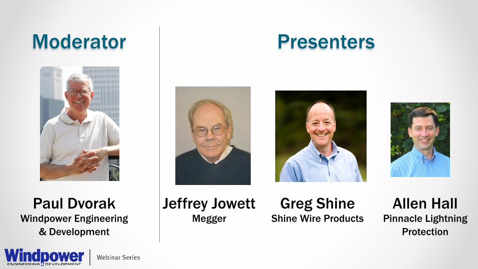
Moderator Presenters
Paul Dvorak Windpower Engineering
& Development
Greg Shine Shine Wire Products
Jeffrey Jowett Megger
Allen Hall Pinnacle Lightning
Protection
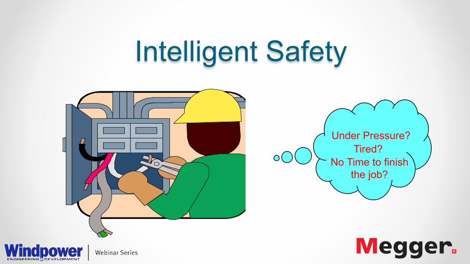
Intelligent Safety
Under Pressure? Tired?
No Time to finish the job?

Safety must be considered from:
• The tester
• The test item

Test Instruments:
• Insulation Tester
• Power Factor
• Winding Resistance

The Tester: Despite high voltage, insulation testers are safe. Current and power are small. To test insulation, you don’t NEED a lot of current. Hence, total current output can be kept small. BUT, be aware of the physical environment.

The Tester: Redundant safety features – IEC61010 arc flash/arc blast protection Safety warnings and indicators Safe design of test leads

The Test Item: De-energized is not “safe”. Standard Safety Practices Lock-out/tag-out Safety enhancements in quality testers:
Discharge test item Let operator know

Safety Standards: • IEEE 62-1995
• IEEE C57.152
• IEEE 510-1983
• IEEE Recommended Practices for Safety in High-Voltage and High-Power Testing
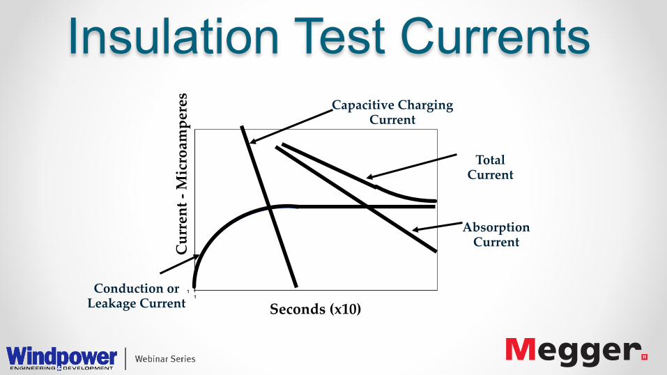
Insulation Test Currents
11
Capacitive Charging Current
Total Current
Conduction or Leakage Current
Current -‐‑ Microamperes
Seconds (x10)
Absorption Current

Insulation Test Currents
Equivalent Circuit of Insulation
Leakage
Absorption Capacitance

Polarization/Absorption Effects
-‐‑
+
-‐‑
+
-‐‑
+ -‐‑
+
+
-‐‑
+ + + +
-‐‑ -‐‑ -‐‑ -‐‑ -‐‑
+
+
-‐‑
-‐‑
+
+
-‐‑ -‐‑
+ -‐‑ + -‐‑
+ + +
-‐‑
-‐‑ -‐‑
+
Stored Charge
Surface Leakage
Dipoles

Safety Rating - IEC • Dictates design considerations - ensure instrument is
adequate for hazards of test environment. • IEC1010 rating consists of two designations; make sure
both are specified: - CAT (category). - voltage.
• Determine the highest-rated environment where the instrument will be used.
• Do not buy an instrument without a rating.

High Installation CAT rating • MIT & S1= CATIV 600V rated • IEC1010-1:2001
• Protection against input transients between any terminals
• CATIII 300V • 4kV transient
protected
• CATIV 600V • 8kV transient
protected

Safety philosophy • What happens in substations? • CATIV 600V in a 33kV substation means little….? • 5kV and 10kV insulation testers get used where 1kV
testers don’t • No one can protect against foreseeable misuse here!

Standard Safe Working Practices
• Boots & Gloves
• Barriers
• Beacon

CAUTION: Inductive Source • Safety grounds • Voltage indicator • Discharge stick
Make 1st/break last
Power Factor = Redundant Safety
• Hand/foot interlocks • Dual ground testing • Circuit breaker protection • Grounded between tests • High voltage and open ground indicators • Arc clearance

Advanced Microprocessor controlled System protects user and instrument in the event of accidental connection to live systems
• Contact Detector - Prevents free probe becoming live if other probe contacts live voltage.
• Live Circuit Warning - Warns if probes connected to >25V
• Test Inhibit - Prevents tests when dangerous external voltages exist
• Auto-Discharge -Safely discharges connected circuits after insulation test
• Default Voltmeter - Displays external voltages even when switched to non-voltage ranges
Beware of lesser Systems!
Intelligent Safety System

Contact Detector Concept • Maintains High Impedance between probes until safe contact is
made with the circuit under test. Benefits • Increased Safety - User will not receive a shock if one probe
accidentally contacts a live circuit.

Contact Detector - Additional Benefits
No fuse blowing - (Some instruments can blow their internal fuses if voltage present between the points tested): • Difficulty finding replacements and wastes time • Voids calibration seals if instrument has to be opened
The contact detector’s high impedance state leaves the fuse intact. Even then…
• A replacement is provided in the battery compartment • The instrument case does not need to be opened, (calibration seals remain intact)

1. Safety! – the big issue • High energy environments? • Concern over receiving shock from instrument
• The danger is actually the after effects
Don’t Overlook Leads:
Large finger guards to keep fingers back
from live parts
Side Pivot guards maintain creepagepaths
Pivot guard maintains clearance
Large finger guards to keep fingers back
from live parts
Side Pivot guards maintain creepagepaths
Pivot guard maintains clearance
Finns increase surface creepage distance
Finns Finns increase surface creepage distance
Finns

Keeping Turbines and Workers Safe with Lightning Diverters Allen Hall – Pinnacle Lightning Protection, LLC Greg Shine – Shine Wire Products, Inc. WXGUARDWIND.COM

Lightning Damage to Turbine Blades
• Lightning strikes account for roughly 25% of loss claims in US
• Most lightning damage occurs to blades • Blade claims average 240,000 USD
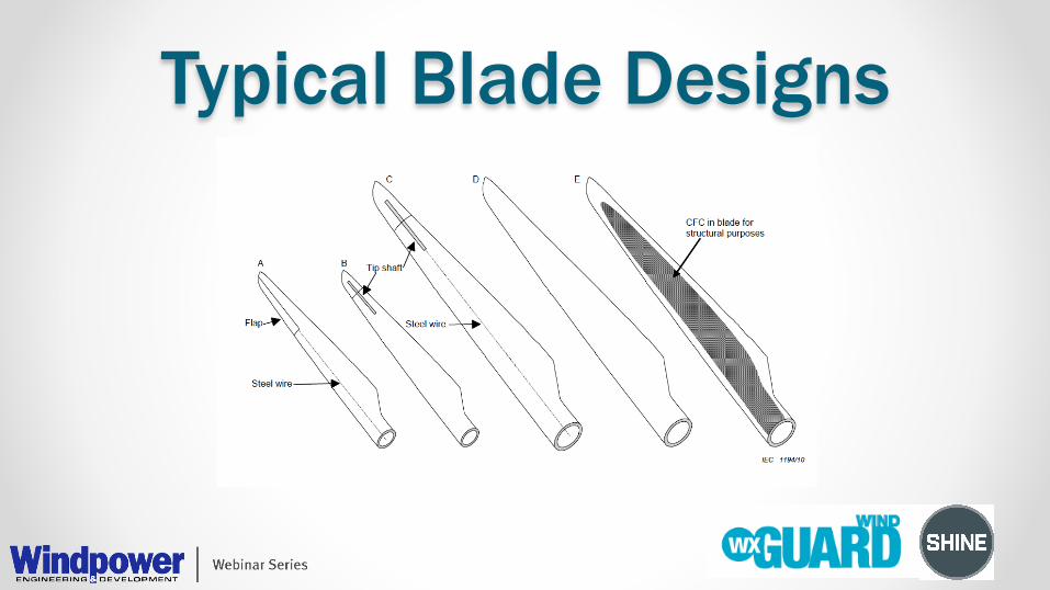
Typical Blade Designs

Typical Blade Protection

Typical Lightning Strikes • Most strikes occur within 4 to 5 meters of tip
• Peak currents of 5 to 20 kA • IEC 61400-24/62305-1
o 200kA o 10 MJ/ohm

Lightning Receptors

Inside the Blade Tip
Receptor
Metal Mounting Block Down
Conductor

Electrical Breakdown Around Thunderstorm
High Voltage Electrical Activity at Mounting Block
Damage to Blade Structure

Near Strikes
Polytechnic University of Catalonia in Barcelona, Spain
• Electrical activity at nearly every rotation of blade
• Duration o Few minutes o Few hours
• Effects seen with storms several kilometers away

Near Strikes • Most lightning damage to blades occurs over time
• Near strikes break down blade dielectric around receptor • Eventual lightning attachment results in more damage to
blade
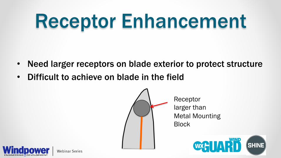
Receptor Enhancement
• Need larger receptors on blade exterior to protect structure • Difficult to achieve on blade in the field
Receptor larger than Metal Mounting Block

Segmented Lightning Diverters

Typical Installation
Lightning Receptors
Internal Down Conductor
WXGuard Lightning Diverters

Segmented Diverter Operation
Ionized Channel Above Diverter Glass Fiber Reinforced
Plastic Blade Surface Segmented Lightning Diverter
Receptor
Down Conductor
Metal Segments of Diverter
Mounting Block
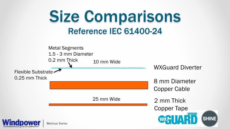
Size Comparisons Reference IEC 61400-24
Metal Segments 1.5 - 3 mm Diameter 0.2 mm Thick
Flexible Substrate 0.25 mm Thick
10 mm Wide
8 mm Diameter Copper Cable
2 mm Thick Copper Tape
WXGuard Diverter
25 mm Wide
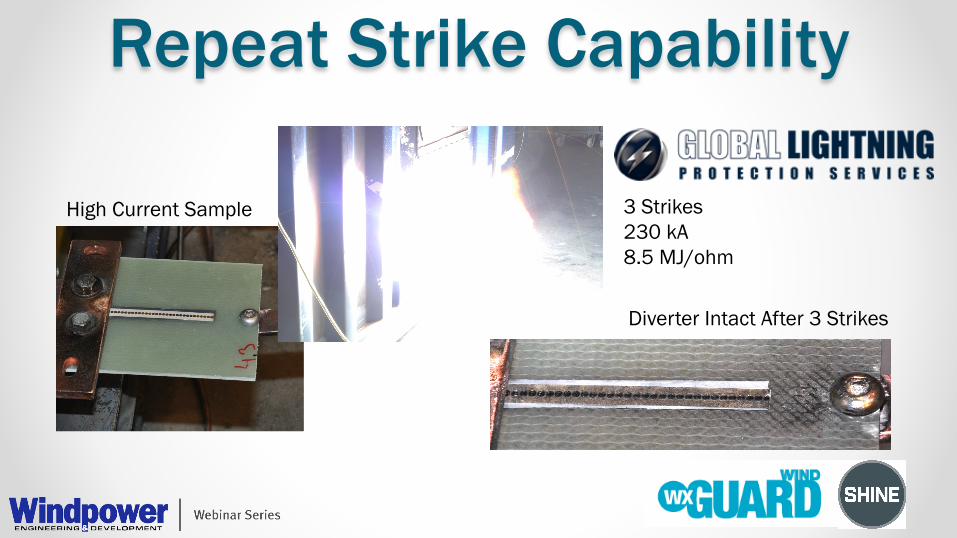
Repeat Strike Capability
High Current Sample 3 Strikes 230 kA 8.5 MJ/ohm
Diverter Intact After 3 Strikes

Rain Erosion
Standard Segmented Diverter WXGuard Diverter

Segmented Diverter Benefits
• Improve protection to existing blades • Lightweight and flexible • Installed with standard epoxy or 3M VHB Tape • Repeat strike capable • Rain erosion resistant

Thank You
• Visit WXGUARDWIND.COM • Free White Papers • Free Test Reports • Free Installation Guide

Questions? Paul Dvorak Windpower Engineering & Development [email protected] Twitter: @windpower_eng
Greg Shine Shine Wire Products [email protected]
Allen Hall Pinnacle Lighting Protection [email protected]
Jeffrey Jowett Megger [email protected]

Thank You q This webinar will be available at
www.windpowerengineering.com & email
q Tweet with hashtag #WindWebinar
q Connect with Windpower Engineering & Development
q Discuss this on the EngineeringExchange.com