KD 225-315-350-400-440
74
KD225 - KD315 - KD350 KD400 - KD440 WORKSHOP MANUAL
-
Upload
giusy-e-gerry -
Category
Documents
-
view
48 -
download
1
Transcript of KD 225-315-350-400-440

KD225 - KD315 - KD350 KD400 - KD440
WORKSHOP MANUAL

KD 225_315_350_400_440
PREFACE
- Every attempt has been made to present within this service manual, accurate and up to date technicalinformation.
However,developmentontheKOHLERseriesiscontinuous. Therefore,theinformationwithinthismanualissubjecttochangewithoutnoticeandwithoutobligation.
- TheinformationcontainedwithinthisservicemanualisthesolepropertyofKOHLER. As such, no reproduction or replication in whole or part is allowed without the express written permission of
KOHLER.
Informationpresentedwithinthismanualassumesthefollowing:
1- ThepersonorpeopleperformingserviceworkonKOHLERseriesenginesisproperlytrainedandequippedtosafelyandprofessionallyperformthesubjectoperation;
2- The person or people performing service work onKOHLER series engines possesses adequate hand andKOHLERspecialtoolstosafelyandprofessionallyperformthesubjectserviceoperation;
3- ThepersonorpeopleperformingserviceworkonKOHLERseriesengineshasreadthepertinentinformationregardingthesubjectserviceoperationsandfullyunderstandstheoperationathand.
- This manual was written by the manufacturer to provide technical and operating information to authorisedKOHLERafter-salesservicecentrestocarryoutassembly,disassembly,overhauling,replacementandtuningoperations.
- Aswellasemployinggoodoperatingtechniquesandobservingtherighttimingforoperations,operatorsmustreadtheinformationverycarefullyandcomplywithitscrupulously.
- Timespentreadingthisinformationwillhelptopreventhealthandsafetyrisksandfinancialdamage. Writteninformationisaccompaniedbyillustrationsinordertofacilitateyourunderstandingofeverystepofthe
operatingphases.

- 3 -
WARRANTY CERTIFICATE
KD 225_315_350_400_440 Workshop Manual_cod. ED0053029330_1° ed_ rev.00
CALIFORNIA EMISSION CONTROL WARRANTY STATEMENTYOUR WARRANTY RIGHTS AND OBLIGATIONS
The California Air Resources Board andKohlerCo.arepleasedtoexplaintheemission control system warrantyonyour2012engine.InCalifornia,newheavy-dutyoff-roadenginesmustbedesigned,builtandequippedtomeettheState’sstringentanti-smogstandards.KohlerCo.mustwarranttheemissioncontrolsystemonyourengineforthetimeperiodlistedbelowprovidedtherehasbeennoabuse,neglectorimpropermaintenanceofyourengine.Youremissioncontrolsystemmay includepartssuchasthefuel-injectionsystemandtheair inductionsystem.Also includedmaybehoses,connectorsandotheremissionrelatedassemblies.Whereawarrantableconditionexists,KohlerCo.willrepairyourheavy-dutyoff-roadengineatnocosttoyouincludingdiagnosis,partsandlabor.
MANUFACTURER’S WARRANTY COVERAGE:
Youroff-road,dieselengineemissioncontrolsystemiscoveredunderwarrantyforaperiodoffive(5)yearsor3,000hours,whicheveroccursfirst,beginningonthedatetheengineorequipmentisdeliveredtoanultimatepurchaserforallconstantspeedengineswithmaximumpower19≤kW<37andratedspeedlessthan3,000rpm,allvariablespeedengineswithmaximumpower19≤kW<37,andallvariableorconstantspeedengineswithmaximumpowergreaterthan37kW.Youroff-road,dieselengineemissioncontrolsystemonvariableorconstant-speedengineswithmaximumpowerlessthan19kW,andforconstantspeedengineswithmaximumpower19≤kW<37andratedspeedequaltoorgreaterthan3,000rpmiscoveredunderwarrantyforaperiodoftwo(2)yearsor1,500hours,whicheveroccursfirst.Ifanyemissionrelatedpartonyourengineisdefective,thepartwillberepairedorreplacedbyKohlerCo.
OWNER’S WARRANTY RESPONSIBILITIES:
As theheavy-dutyoff-roadengineowner,youare responsible for theperformanceof the required maintenance listed in your Kohler Co. owner’s manual.KohlerCo.recommendsthatyouretainallreceiptscoveringmaintenanceonyourheavy-dutyoff-roadengine,butKohlerCo.cannotdenywarrantysolelyforthelackofreceiptsorforyourfailuretoensuretheperformanceofallrecommendedscheduledmaintenance.Astheheavy-dutyoff-roadengineowner,youshouldhoweverbeawarethatKohlerCo.maydenyyouwarrantycoverageifyourheavy-dutyoff-roadengineoremissioncontrolrelatedcomponenthasfailedduetoabuse,neglect,impropermaintenanceorunapprovedmodifications.Yourengineisdesignedtooperateoncommercialdieselfuel(No.1orNo.2lowsulfurorultralowsulfurdieselfuel)only.UseofanyotherfuelmayresultinyourenginenolongeroperatingincompliancewithCalifornia’semissionsrequirements.Youareresponsibleforinitiatingthewarrantyprocess.TheAirResourcesBoardsuggeststhatyoupresentyourheavy-dutyoff-roadenginetoaKohlerCo.dealerassoonasaproblemexists.Thewarrantyrepairsshouldbecompletedbythedealerasexpeditiouslyaspossible.Pleasereviewthedocumenttitled,“KohlerCo.FederalandCaliforniaEmissionControlSystemsLimitedWarrantyOff-RoadDieselEngines”,forcompletedetailsofyourheavy-dutyoff-roadenginewarranty.IfyouhaveanyquestionsregardingyourwarrantyrightsandresponsibilitiesorthelocationofthenearestKohlerCo.authorizedservicelocation,youshouldcontactKohlerCo.at1-800-544-2444oraccessourwebsiteatwww.kohlerengines.com.
LIMITED 3 YEAR KOHLER® DIESEL ENGINE WARRANTY
KohlerCo.warrantstotheoriginalretailconsumerthateachnewKOHLERDieselenginesoldbyKohlerCo.willbefreefrommanufacturingdefects inmaterialsorworkmanship innormal service for aperiodof three (3) yearsor2000hourswhicheveroccurs first from thedateofpurchase,provideditisoperatedandmaintainedinaccordancewithKohlerCo.’sinstructionsandmanuals.Ifnohourmeterisinstalledasoriginalequipmentthen8hoursofuseperdayand5daysperweekwillbeusedtocalculatehoursused.
Ourobligationunderthiswarrantyisexpresslylimited,atouroption,tothereplacementorrepairatKohlerCo.,Kohler,Wisconsin53044,orataservicefacilitydesignatedbyusofsuchpartsasinspectionshalldisclosetohavebeendefective.
Thiswarrantydoesnotapplytodefectscausedbyunreasonableuse,includingfaultyrepairsbyothersandfailuretoprovidereasonableandnecessarymaintenance.
Thefollowingitemsarenotcoveredbythiswarranty:Engineaccessoriessuchasfueltanks,clutches,transmissions,power-driveassembliesandbatteries,unlesssuppliedorinstalledbyKohlerCo.Thesearesubjecttothewarranties,ifany,oftheirmanufacturers.
KOHLERCO.AND/ORTHESELLERSHALLNOTBELIABLEFORSPECIAL,INDIRECT,INCIDENTIALORCONSEQUENTIALDAMAGESOFANYKIND,includingbutnotlimitedtolaborcostsortransportationchargesinconnectionwiththerepairorreplacementofdefectiveparts.
IMPLIEDORSTATUTORYWARRANTIES,INCLUDINGWARRANTIESOFMERCHANTABILITYORFITNESSFORAPARTICULARPURPOSE,AREEXPRESSLYLIMITEDTOTHEDURATIONOFTHISWRITTENWARRANTY.Wemakenootherexpresswarranty,norisanyoneauthorizedtomakeanyonourbehalf.
Somestatesdonotallowlimitationsonhowlonganimpliedwarrantylasts,ortheexclusionorlimitationofincidentalorconsequentialdamages,sotheabovelimitationorexclusionmaynotapplytoyou.
Thiswarrantygivesyouspecificlegalrights,andyoumayalsohaveotherrights,whichvaryfromstatetostate.
Toobtainwarrantyservice
PurchasermustbringtheenginetoanauthorizedKohlerservicefacility.Tolocatethenearestfacility,visitourwebsite,www.kohlerengines.com,andusethelocatorfunction,consultyourYellowPagesortelephone1-800-544-2444.
ENGINEDIVISION,KOHLERCO.,KOHLER,WISCONSIN53044

- 4 -
INDEX
KD 225_315_350_400_440 Workshop Manual_cod. ED0053029330_1° ed_ rev.00
ThismanualcontainspertinentinformationregardingtherepairofKOHLERwater-cooled,indi-rectinjectionDieselenginestypeKD 225_315_350_400_440:updatedJune20,2012.INDEX
PREFACE .................................................................................................................................................................. 2
WARRANTY CERTIFICATE ..................................................................................................................................... 3Limited3yearkohler®dieselenginewarranty.................................................................................................................. 3Californiaemissioncontrolwarrantystatement................................................................................................................. 3Yourwarrantyrightsandobligations.................................................................................................................................. 3
1 - TROUBLE SHOOTING ........................................................................................................................................ 7Possiblecausesandtroubleshooting................................................................................................................................ 7
2 - GENERAL REMARKS AND SAFETY INFORMATION ...................................................................................... 8Safetyregulations............................................................................................................................................................... 8Generalsafetyduringoperatingphases............................................................................................................................ 9Safetyandenvironmentalimpact...................................................................................................................................... 9
3 - MODEL NUMBER AND IDENTIFICATION ....................................................................................................... 11Manufacturerandmotoridentificationdata.......................................................................................................................11Approvaldata.....................................................................................................................................................................11
4 - TECHNICAL DATA ............................................................................................................................................ 12Characteristicskd225_315_350.......................................................................................................................................12Characteristicskd400_440...............................................................................................................................................13
5 - CHARACTERISTICS ......................................................................................................................................... 14Characteristicspower,torqueandspecificfuelconsumptioncurves...............................................................................14
6 - OVERALL DIMENSIONS ................................................................................................................................... 16
7 - MAINTENANCE - RECOMMENDED OIL TYPE - REFILLING ........................................................................ 18Maintenance......................................................................................................................................................................18Fuel....................................................................................................................................................................................18Recommendedoil..............................................................................................................................................................19Aceasequences................................................................................................................................................................19
8 - DISASSEMBLY/REASSEMBLY ........................................................................................................................ 20Disassemblyandreassembly........................................................................................................................................... 20Dryaircleanerforkd315andkd350............................................................................................................................... 20Dryaircleanerforkd225................................................................................................................................................. 20Dryaircleanerforkd400-440..........................................................................................................................................21Prefilterfordryairfilter......................................................................................................................................................21Oil-bathaircleaner(optional)........................................................................................................................................... 22Muffler............................................................................................................................................................................... 22Rockerarmcoverbreathersystem................................................................................................................................... 22Rockerarmcover-breatherricirculation......................................................................................................................... 23Valve/rockerarmclearance(KD225-315-350)................................................................................................................ 23TheenginesKD400and440havehydraulictappets,thereforenoadjustmentisrequired........................................... 23Donotstarttheengineforapproximately4hourstoallowthehydraulictappetstosettlecompletely........................... 23HydraulictappetsKD400-440........................................................................................................................................ 24Tank.................................................................................................................................................................................. 25FuelfilterKD225-400-440(versionwithinternalfilter)................................................................................................... 25FuelfilterforKD225-315-350-400-440(versionwithexternalfilter)........................................................................ 25Re-coilstarting.................................................................................................................................................................. 26Shroud.............................................................................................................................................................................. 26Flywheel............................................................................................................................................................................ 26

- 5 -
INDEX
KD 225_315_350_400_440 Workshop Manual_cod. ED0053029330_1° ed_ rev.00
Cylinderhead.................................................................................................................................................................... 27Injectorprojection............................................................................................................................................................. 27Valves-Disassembly........................................................................................................................................................ 28Valves-Oilsealinvalveguide......................................................................................................................................... 28Valve,springs.................................................................................................................................................................... 28Valves,characteristics...................................................................................................................................................... 29Valves,guidesandhousings............................................................................................................................................ 29Valves,guideinsertion...................................................................................................................................................... 29Dimensionsandclearancebetweenguidesandvalvestems(mm)................................................................................ 30Valvesseatsandvalveseatbores................................................................................................................................... 30Valveseatlapping............................................................................................................................................................. 30Cylinder..............................................................................................................................................................................31Cylinderroughness............................................................................................................................................................31Piston.................................................................................................................................................................................31Dimensionsofpistonsandcylinders,Logo.......................................................................................................................31Pistonrings,distancebetweenthetips(mm)................................................................................................................... 33Pistonrings,playbetweentheslots(mm)........................................................................................................................ 34Pistonrings,assemblyorder............................................................................................................................................ 34Piston-Refitting............................................................................................................................................................... 34Clearance.......................................................................................................................................................................... 34Pistonprotrusioncheck.................................................................................................................................................... 35Connectingrod................................................................................................................................................................. 36Connectingrod,pistonpin................................................................................................................................................ 36Connectingrodalignement............................................................................................................................................... 36Crankshaftendplay.......................................................................................................................................................... 36Driveshaftoilseals........................................................................................................................................................... 37Driveshaft,lubricationducts,borethreadonflywheelsideandp.t.o.............................................................................. 37Driveshaft,connectionradius.......................................................................................................................................... 37Driveshaft,mainjournal/crankpindiameter,gearcoverbearinginsidediameterontimingside.................................... 37Crankshaft-journaldiameter(mm).................................................................................................................................. 38Availabilityofbearings...................................................................................................................................................... 38Camshaft........................................................................................................................................................................... 39Camshaftjournalsandbore............................................................................................................................................. 39Dimensionsofcamshaftjournalsandbore(mm)............................................................................................................. 39Camheight(mm)............................................................................................................................................................... 39Camshafttiming................................................................................................................................................................ 40Camshaft–AntireversesystemKD400-440................................................................................................................... 40Automaticdecompression.................................................................................................................................................41Camshaftendplay.............................................................................................................................................................41Dynamicbalancer(onrequest)..........................................................................................................................................41Dinamicbalancertiming................................................................................................................................................... 43Valvetimingcheck............................................................................................................................................................ 43Timinganglesforoperation(0.15valveplay)................................................................................................................... 44Timinganglesforinspection(0.65-0.70valveplay)......................................................................................................... 44Speedgovernor................................................................................................................................................................ 45Speedgovernorremoval.................................................................................................................................................. 45Refittinggearcoverontimingside................................................................................................................................... 45
9 - LUBRICATION SYSTEM .................................................................................................................................... 46KD225-315-350lubricationsystemandbreatherrecirculationsystem...................................................................... 46KD400-440lubricationsystemandbreatherrecirculationsystem..................................................................................47Oilpump............................................................................................................................................................................ 48Oilpump-clearancebetweenrotors............................................................................................................................... 48Oilpressureregulationvalve............................................................................................................................................ 48Internalstrainer................................................................................................................................................................. 48Oilfilter.............................................................................................................................................................................. 49Oilpressurecheck............................................................................................................................................................ 49Calibratedpipeforlubricationofhydraulictappets.......................................................................................................... 49Oilpressurecurveatidlespeed....................................................................................................................................... 50Oilpressurecurveatfullspeed........................................................................................................................................ 50Fuelling/injectioncircuitforKD315-350-400-440............................................................................................................51Fuelling/injectioncircuitforKD225...................................................................................................................................51

- 6 -
INDEX
KD 225_315_350_400_440 Workshop Manual_cod. ED0053029330_1° ed_ rev.00
10 - FUEL SYSTEM ................................................................................................................................................. 52FuelfilterKD225-315-350-400-440................................................................................................................................ 52FuelfilterKD225(versionwithinternalfilterintank)....................................................................................................... 52Feedpump(optional)........................................................................................................................................................ 52Fuelpump,driverodprotrusion........................................................................................................................................ 53Injectionpump.................................................................................................................................................................. 53Injectionpumpfittinginthecrankcase............................................................................................................................. 53Injectionpumpcomponentsanddisassembly................................................................................................................. 54Injectionpump,body,plungeranddeliveryvalve............................................................................................................. 54Injectionpumprefitting..................................................................................................................................................... 54Injectionpumpnon-returnvalve....................................................................................................................................... 55Outletfittingcomponentsfor315-350EPAE400-440engines...................................................................................... 55Injectionpump,Rilsantuberemoval................................................................................................................................ 55Injectionpump,Rilsantuberefitting................................................................................................................................. 55Injectionpumpdeliverycheckontestbench................................................................................................................... 56Staticinjectiontiming........................................................................................................................................................ 56Staticinjectionleadtestonflywheel................................................................................................................................. 57Injectionadvanceadjustment........................................................................................................................................... 58Injector.............................................................................................................................................................................. 58Leakagetime(waste)........................................................................................................................................................ 59Nozzles............................................................................................................................................................................. 59Injectorcalibration............................................................................................................................................................. 59
11 - ELECTRICAL SYSTEM .................................................................................................................................... 6212V,12Aelectricignitiondiagram.....................................................................................................................................61Alternator...........................................................................................................................................................................61Alternatorbatterychargergraph(12V,12A)......................................................................................................................6124V,9Aalternatorbatteryrechargingcurve..................................................................................................................... 6212V,30Aalternatorbatteryrechargingcurve................................................................................................................... 62Voltageregulator............................................................................................................................................................... 6212Velectricstarterdiagramwithvoltageregulatorbuiltintotheignitionpanel............................................................... 6312Velectricignitionlayoutwithmotorprotection(optional)............................................................................................. 63Diagramofelectricstartermotorprotectionwithsoleself-windingstarter-withoutbattery-(optional)......................... 64Testingvoltageregulatorforproperoperation................................................................................................................. 65Startingmotor................................................................................................................................................................... 65CharacteristiccurvesforstartingmotortypeDW(L)12V,1.1KW.................................................................................. 65CharacteristiccurvesofBoschstartermotortypeDW(L)12V,0.9kW........................................................................... 66CharacteristiccurvesofBoschstartermotortypeDW(L)24V,1.6kW........................................................................... 66Ignitionswitchpositions.................................................................................................................................................... 66Adjustments-KD315-350................................................................................................................................................ 67Idlingspeedsettinginno-loadconditions(standard)....................................................................................................... 67Idlespeedadjustment,forsmallcarversions.................................................................................................................. 67Fullspeedsettinginno-loadconditions(standard).......................................................................................................... 67
12 - SETTINGS / ADJUSTMENTS .......................................................................................................................... 68Adjustments-KD225-400-440....................................................................................................................................... 68No-loadidlingadjustment(standard)................................................................................................................................ 68No-loadtoprateadjustment(standard)............................................................................................................................ 68InjectionpumpflowrateadjustmentForKD225-315-350-400-440............................................................................... 68Injectionpumpdeliverylimitingandtorqueadapter(standard)....................................................................................... 68Injectionpumpdeliverysetting........................................................................................................................................ 69Requiredsettings(themostcommonones)..................................................................................................................... 69
14 - STORAGE ........................................................................................................................................................ 70Storage............................................................................................................................................................................. 70Internalengineprotection:................................................................................................................................................ 70Injectionsystemsprotection:............................................................................................................................................ 70Externalengineprotection:............................................................................................................................................... 70Procedurestobecarriedoutbeforestarttheengine........................................................................................................71
15 - TORQUE SPECIFICATIONS ........................................................................................................................... 72Maintorquespecifications................................................................................................................................................ 72Useofsealant................................................................................................................................................................... 72Tableoftighteningtorquesforstandardscrews(coarsethread)..................................................................................... 73Tableoftighteningtorquesforstandardscrews(finethread).......................................................................................... 73

1
- 7 -
POSSIBLE CAUSES AND TROUBLE SHOOTING
CloggedpipesCloggedfuelfilterAirinsidefuelcircuitCloggedtankbreatherholeFaultyfuelpumpInjectorjammedJammedinjectionpumpdeliveryvalveWronginjectorsettingExcessiveplungerblow-byJammedinjectionpumpdeliverycontrolWronginjectionpumpsettingOilleveltoohighJammedpressurereliefvalveWornoilpumpAirinsideoilsuctionpipeFaultypressuregaugeorswitchCloggedoilsuctionpipeBatterydischargedWrongorinefficientcableconnectionDefectiveignitionswitchDefectivestartermotorCloggedairfilterExcessiveidleoperationIncompleterunning-inEngineoverloadedAdvancedinjectionDelayedinjectionIncorrectgovernorlinkageadjustmentBrokenorloosegovernorspringIdlespeedtoolowWornorjammedpistonringsWornorscoredcylindersWornvalveguidesJammedvalvesWornbearingsGovernorlinkagenotfreetoslideDriveshaftnotfreetoslideDamagedcylinderheadgasket
TROUBLE
LUBR
ICAT
ION
POSSIBLE CAUSE
FUEL
CIR
CU
ITEL
ECTR
ICSY
STEM
MA
INTE
-N
AN
CE
SETT
ING
S/R
EPA
IRS
Enginedoesnot
start
Noacceleration
Blacksmoke
Excessiveoil
consum
ption
Too
low
oil
pressure
Enginestartsbut
stops
Non-uniformspeed
Whitesmoke
oilandfu
eldripping
fromexhaust
Increaseoillevel
THE ENGINE MUST BE STOPPED IMMEDIATELY WHEN:
1) -Theenginerpmssuddenlyincreaseanddecrease 2) -Asuddenandunusualnoiseisheard 3) -Thecolouroftheexhaustfumessuddenlydarkens 4) -Theoilpressureindicatorlightturnsonwhilerunning.
TABLE OF LIKELY ANOMALIES AND THEIR SYMPTOMS
Thefollowingtablecontainsthepossiblecausesofsomefailureswhichmayoccurduringoperation.Alwaysperformthesesimplechecksbeforeremovingorreplacinganypart.
TROUBLE SHOOTING
KD 225_315_350_400_440 Workshop Manual_cod. ED0053029330_1° ed_ rev.00

2
- 8 -
SAFETY REGULATIONS
GENERAL REMARKS AND SAFETY INFORMATION
KD 225_315_350_400_440 Workshop Manual_cod. ED0053029330_1° ed_ rev.00
GENERAL NOTES
. Kohler engines are built to provide safe and longlastingperformances, but in order to obtain these results it isessential that the maintenance requirements described inthe manual are observed along with the following safetyrecommendations.
. The engine has been built to the specifications of amachinemanufacturer,anditishisresponsibilitytoensurethat all necessary action is taken to meet the essentialand legally prescribed health and safety requirements.Any use of themachine other than that described cannotbe considered as complying with its intended purposeas specified by Kohler, which therefore declines allresponsibilityforaccidentscausedbysuchoperations.
. The following instructions are intended for the user of themachine in order to reduce or eliminate risks, especiallythoseconcerning theoperationandstandardmaintenanceoftheengine.
. The user should read these instructions carefully and gettoknowtheoperationsdescribed.Bynotdoingsohemayplaceatriskhisownhealthandsafetyandthatofanyoneelseinthevicinityofthemachine.
. The enginemay be used ormounted on amachine onlybypersonnelsuitably trained in itsoperationandawareofthedangers involved.This is particularly true for standardand, above all, special maintenance work. For specialmaintenance contact personnel trained specifically byKohler.Thisworkshouldbecarriedoutinaccordancewithexistingliterature.
. Kohlerdeclinesallresponsibilityforaccidentsorforfailuretocomplywiththerequirementsoflawifchangesaremadetotheengine’sfunctionalparametersortothefuelflowrateadjustments and speed of rotation, if seals are removed,or ifpartsnotdescribed in theoperatingandmaintenancemanual are removed and reassembled by unauthorizedpersonnel.
WARNING
. Inaddition toall othermachinespecifications,ensure thattheengine is inanearhorizontalpositionwhenstarting. lfstarting manually, ensure that the necessary operationscanbeperformedwithoutanyriskofstrikingagainstwallsordangerousobjects.Ropestarting(exceptforrecoilropestarting)isnotpermittedeveninemergencies.
. Checkthatthemachineisstablesothatthereisnoriskofitoverturning.
. Get to know the engine speed adjustment and machinestopoperations.
. Do not start the machine in closed or poorly ventilatedenvironments.The internal combustion process generatescarbon monoxide, an odourless and highly toxic gas, sospending too long a time in an environment where theengine discharges its exhaust products freely can lead tolossofconsciousnessandevendeath.
. The engine may not be used in environments containingflammable materials, explosive atmospheres or easilycombustible powders, unless adequate and specificprecautions have been taken and are clearly stated andcertifiedforthemachine.
. Topreventtheriskoffire,keepthemachineatadistanceofatleastonemetrefrombuildingsorothermachines.
. Children and animals must be kept at a sufficient distancefrom the machine to prevent any danger resulting from itsoperation.
. Fuel is flammable, so the tankmust be filled only when theengine is turned off. Dry carefully any fuel that may havespilled, remove the fuel container and any cloths soakedin fuel or oil, check that any sound-absorbing panels madeofporousmaterial arenot soakedwith fueloroil, andmakesurethatthegroundonwhichthemachineislocatedhasnotabsorbedfueloroil.
. Before starting, remove any tools that have been used forcarrying out maintenance work to the engine and/or themachine and check that any guards removed have beenreplaced. Incoldclimates it ispossible tomixkerosenewiththediesel fuel tomaketheengineeasier tostart.Theliquidsmust be mixed in the tank by pouring in first the keroseneand then the diesel fuel. ConsultKohler technical office formixture proportions. Petrolmay not be used because of theriskofitformingflammablevapours.
. During operation the surface of the engine reachestemperatures thatmaybe dangerous. Avoid in particular allcontactwiththeexhaustsystem.
. The liquid cooling circuit is underpressure.Donot carryoutany checks before the engine has cooled down, and eventhenopen the radiator capor theexpansion tank cautiously.Wear protective clothing and glasses. lf there is an electricfan,donotapproachtheenginewhile it isstillhotasthefanmaycomeonevenwhentheengineisnotrunning.Cleanthecoolingsystemwiththeengineturnedoff.
. While cleaning the oil bath air filter, check that the oil isdisposed of in such a way as not to harm the environment.Any filtering sponges in the oil bath air filter should not besoakedwithoil. Thecyclonepre-filtercupmustnotbefilledwithoil.
. Sincetheoilmustbeemptiedoutwhiletheengineisstillhot(approx. 80°C), particular care should be taken in order toavoid burns. In any casemake sure that oil does not comeinto contact with your skin because of the health hazardsinvolved.
. Fuelvapoursarehighlytoxic,sofilluponlyintheopenairorinwellventilatedenvironments.
. During operations which involve access to moving parts ofthe engine and/or removal of the rotary guards, disconnectandinsulatethepositivecableofthebatterysoastopreventaccidentalshortcircuitsandactivationofthestartermotor.
. Checkthebelttensiononlywhentheengineisturnedoff.
IMPORTANT
. To start the engine follow the specific instructions providedin the engine and/or machine operating manual. Do notuse auxiliary starting devices not originally installed on themachine(e.g.Startpilotsystemswhichutiliseetheretc.)
. Before carrying out any work on the engine, turn it off andallowittocooldown.Donotperformanyoperationwhiletheengineisrunning.
. Check that the discharged oil, the oil filter and the oilcontainedintheoilfilteraredisposedofinsuchawayasnottoharmtheenvironment.
. Close the fuel tank filler cap carefully after each fíllingoperation. Do not fill the tank right up to the top, but leavesufficientspacetoallowforanyexpansionofthefuel.
. Donotsmokeorusenakedflameswhilefilling.

2
- 9 -
GENERAL SAFETY DURING OPERATING PHASES
– Theprocedurescontainedinthismanualhavebeentestedandselectedbythemanufacturer’stechnicalexperts,andhencearetoberecognisedasauthorisedoperatingmethods.
– Anumberof proceduresmustbe carriedoutwith theaidof equipmentand tools that simplify and improve the timingofoperations.
– Alltoolsmustbeingoodworkingconditionsothatenginecomponentsarenotdamagedandthatoperationsarecarriedoutproperlyandsafely.
Itisimportanttowearthepersonalsafetydevicesprescribedbyworksafetylawsandalsobythestandardsofthismanual.– Holes must be lined up methodically and with the aid of suitable equipment. Do not use your fingers to carry out this
operationtoavoidtheriskofamputation.– Somephasesmayrequiretheassistanceofmorethanoneoperator.Ifso,itisimportanttoinformandtrainthemregarding
thetypeofactivitytheywillbeperforminginordertopreventriskstothehealthandsafetyofallpersonsinvolved.– Donotuseflammableliquids(petrol,diesel,etc.)todegreaseorwashcomponents.Usespecialproducts.– Usetheoilsandgreasesrecommendedbythemanufacturer. Donotmixdifferentbrandsorcombineoilswithdifferentcharacteristics.– Discontinueuseoftheengineifanyirregularitiesarise,particularlyinthecaseofunusualvibrations.– Donottamperwithanydevicestoalterthelevelofperformanceguaranteedbythemanufacturer.
SAFETY AND ENVIRONMENTAL IMPACT
Every organisation has a duty to implement procedures toidentify,assessandmonitor the influenceof itsownactivities(products,services,etc.)ontheenvironment.Proceduresforidentifyingtheextentoftheimpactontheenvi-ronmentmustconsiderthefollowingfactors:
- Liquidwaste - Wastemanagement - Soilcontamination - Atmosphericemissions - Useofrawmaterialsandnaturalresources - Regulationsanddirectivesregardingenvironmentalimpact
Inordertominimisetheimpactontheenvironment,themanu-
facturer nowprovidesanumber of indications to be followedbyallpersonshandling theengine, forany reason,during itsexpectedlifetime.
- All packaging componentsmust be disposed of in accor-dancewiththelawsofthecountry inwhichdisposal ista-kingplace.
- Keepthefuelandenginecontrolsystemsandtheexhaustpipes in efficientworking order to limit environmental andnoisepollution.
- When discontinuing use of the engine, select all compo-nentsaccordingtotheirchemicalcharacteristicsanddispo-seofthemseparately.
GENERAL REMARKS AND SAFETY INFORMATION
KD 225_315_350_400_440 Workshop Manual_cod. ED0053029330_1° ed_ rev.00
. Takecarewhenremovingtheoilfilterasitmaybehot.
. The operations of checking, filling up and replacing thecoolingliquidmustbecarriedoutwiththeengineturnedoffandcold. Takeparticular care if liquids containingnitritesare mixed with others not containing these compoundsas this may give rise to the formation of nitrosamineswhichareahealthhazard. Thecooling liquid ispolluting,so dispose of in a manner that does not damage theenvironment.
. In order to move the engine simultaneously use theeyebolts fitted for this purpose by Kohler. These liftingpointsarehowevernotsuitable for theentiremachine,sointhiscaseusetheeyeboltsfittedbythemanufacturer.

- 10 -
NOTE
KD 225_315_350_400_440 Workshop Manual_cod. ED0053029330_1° ed_ rev.00

3
- 11 -
F EC
A DB
s/n
MADE IN ITALY
rpmXX XX XXXX
XX XX XXXX
XXXX
XXXXXXe9 • 97/68/CE • 00/000xx • xxxx •xx
Xx 0.00 xxx xxx xx
Model
Spec.
6
1
USE IN CONSTANT-SPEED APPLICATIONS ONLY
3 10
5
78
9
2 4
MODEL NUMBER AND IDENTIFICATION
Theidentificationplateshowninthefigurecanbefounddirectlyontheengine.Itcontainsthefollowinginformation:
A)Manufacturer’sidentityB)EnginetypeC)EngineserialnumberD) MaximumoperatingspeedE) Numberofthecustomerversion(formK)F)Approvaldata
Approval data
TheapprovalreferencedirectivesECareontheengineplate.
MANUFACTURER AND MOTOR IDENTIFICATION DATA
1)Modelyear.2)Enginedisplacement.3)Powercategory,kW.4)Particulateemissionlimit(g/kWh).5)EnginefamilyID.6)Kindofapplicationi.e.7)Injectiontiming(BTDC).8)Injectoropeningpressure(bar).9)Productiondate(example2012_Jan).10) EmissionControlSystem=ECS.
KD 225_315_350_400_440 Workshop Manual_cod. ED0053029330_1° ed_ rev.00

4
1786631520,3:13600
5,0(6,8)4,6(6,2)4,1(5,6)15@2400
2620,00351,212/4433480500020025°35°***
1826634920,3:13600
5,5(7,5)5,1(7,0)4,7(6,4)
16,6@2400260
0,00381,212/4433540500020025°35°***
N.mmmmCm3
Nmg/kW.h
l/hlt
V/Ahkg
l./minl./minkg.
1696022421:13600
3,5(4,8)3,3(4,5)3,1(4,2)
10,4@2400267
0,00210,912/3628350380015025°35°***
315 350225
- 12 -
KD 315
KD 350
KD 225
TECHNICAL DATA
* ReferredtoNpower** ReferredtoNBpower*** Dependingontheapplication
ENGINETYPENumberofcylindersBoreStrokeSweptvolumeCompressionratioR.P.M. N80/1269/EEC-ISO1585PowerkW(HP) NBISO3046-1IFN NAISO3046-1ICXNMax.torque*Fuelconsumption**OilconsumptionCapacityofstandardoilsumpRecommendedbatteryDryweightCombustionairvolumeat3600r.p.m.Coolingairvolumeat3600r.p.m.Max.permissibledrivingshaftaxialloadinbothdirections continuousserviceforupto30min.Max.inclination discontinuousserviceforabout1min. permanentservice
KD 225_315_350_400_440 Workshop Manual_cod. ED0053029330_1° ed_ rev.00
CHARACTERISTICS KD 225_315_350

4
1827640120,3:13600
7,0(9,5)6,4(8,7)5,8(7,9)
21,3@24002620,0051,512/4445580550020025°35°***
1867644220,3:13600
7,7(10,5)7,0(9,6)6,4(8,7)
23,5@2400260
0,00551,512/4445635550020025°35°***
N.mmmmCm3
Nmg/kW.h
l/hlt
V/Ahkg
l./minl./minkg.
400 440
- 13 -
KD 400
KD 440
TECHNICAL DATA
* ReferredtoNpower** ReferredtoNBpower*** Dependingontheapplication
ENGINETYPENumberofcylindersBoreStrokeSweptvolumeCompressionratioR.P.M. N80/1269/EEC-ISO1585PowerkW(HP) NBISO3046-1IFN NAISO3046-1ICXNMax.torque*Fuelconsumption**OilconsumptionCapacityofstandardoilsumpRecommendedbatteryDryweightCombustionairvolumeat3600r.p.m.Coolingairvolumeat3600r.p.m.Max.permissibledrivingshaftaxialloadinbothdirections continuousserviceforupto30min.Max.inclination discontinuousserviceforabout1min. permanentservice
KD 225_315_350_400_440 Workshop Manual_cod. ED0053029330_1° ed_ rev.00
CHARACTERISTICS KD 400_440

5
- 14 -
KD 225
KD 315 KD 350
CHARACTERISTICS
CHARACTERISTICS POWER, TORQUE AND SPECIFIC FUEL CONSUMPTION CURVES
KD 225_315_350_400_440 Workshop Manual_cod. ED0053029330_1° ed_ rev.00
N (80/1269/EEC - ISO 1585) AUTOMOTIVE RATING :Intermittentoperationwithvariablespeedandvariableload.NB (ISO 3046 - 1 IFN) RATING WITH NO OWERLOAD CAPABILITY:continuosligthdutyoperationwithconstantspeedandvariableload.NA (ISO 3046 - 1 ICXN) CONTINUOS RATING WITH OVERLOAD CAPABILITY:continuosheavydutywithconstantspeedandconstantload.MN TorqueatNpower.CSpecificfuelconsumptionatNB power.Theabovepowervalues refer toanenginefittedwithair cleanerandstandardmuffler,after testingandat theenvironmental conditionsof20°Cand1bar.Max.powertoleranceis5%.Powerdecreasesbyapproximately1%every100mdialtitudeandby2%every5°Cabove25°C.
Note:ConsultKOHLERforpower,torquecurvesandspecificconsumptionsatratesdifferingfromthosegivenabove.

5
- 15 -
KD 400 KD 440
CHARACTERISTICS
CHARACTERISTICS POWER, TORQUE AND SPECIFIC FUEL CONSUMPTION CURVES
KD 225_315_350_400_440 Workshop Manual_cod. ED0053029330_1° ed_ rev.00
N (80/1269/EEC - ISO 1585) AUTOMOTIVE RATING :Intermittentoperationwithvariablespeedandvariableload.NB (ISO 3046 - 1 IFN) RATING WITH NO OWERLOAD CAPABILITY:continuosligthdutyoperationwithconstantspeedandvariableload.NA (ISO 3046 - 1 ICXN) CONTINUOS RATING WITH OVERLOAD CAPABILITY:continuosheavydutywithconstantspeedandconstantload.MN TorqueatNpower.CSpecificfuelconsumptionatNB power.Theabovepowervalues refer toanenginefittedwithair cleanerandstandardmuffler,after testingandat theenvironmental conditionsof20°Cand1bar.Max.powertoleranceis5%.Powerdecreasesbyapproximately1%every100mdialtitudeandby2%every5°Cabove25°C.
Note:ConsultKOHLERforpower,torquecurvesandspecificconsumptionsatratesdifferingfromthosegivenabove.

6
Note :Dimensionsshowninmm
- 16 -
KD 225
KD 315
KD 350
OVERALL DIMENSIONS
KD 225_315_350_400_440 Workshop Manual_cod. ED0053029330_1° ed_ rev.00

6
Note:Dimensionsshowninmm.
- 17 -
KD 400
KD 440
OVERALL DIMENSIONS
KD 225_315_350_400_440 Workshop Manual_cod. ED0053029330_1° ed_ rev.00

7
10 50 250 500(*)(*)
(**)
(**)(***)
(°)
- 18 -
MAINTENANCE - RECOMMENDED OIL TYPE - REFILLING
Failure to carry out the operations described in the table may lead to technical damage to the machine and/or system
MAINTENANCE INTERVAL (HOURS) OPERATION COMPONENT OIL-BATHAIRCLEANER HEADANDCYLINDERFINSCLEANING INJECTOR AIRCLEANEROIL LEVEL OILSUMPCHECK VALVE/ROCKERARMCLEARANCE INJECTORSETTING AIRCLEANER SUMP REPLACEMENT OILFILTERCARTRIDGE FUELFILTERCARTRIDGE DRYAIRCLEANERCARTRIDGE
(*) Undersevereworkingconditions,cleandaily.(**) Underextremelydustyconditions,changeevery4-5hours.(***) Seerecommendedoiltype.(°)Afterthepolyurethaneprefilterhasbeenserviced6-10times(seefig.2for315-350engines),whentheclogging
indicator(ifinstalled)signalsthatthepartmustbereplaced,orifitisirreparablyclogged.
KD 225_315_350_400_440 Workshop Manual_cod. ED0053029330_1° ed_ rev.00
Toavoidexplosionsorfireoutbreaks,donotsmokeorusenakedflamesduringtheoperations.Fuelvapoursarehighlytoxic.Onlycarryouttheoperationsoutdoorsorinawellventilatedplace.Keepyourfacewellawayfromtheplugtopreventharmfulvapoursfrombeinginhaled.Disposeoffuelinthecorrectwayanddonotlitterasitishighlypolluting.
FUEL
Whenrefuelling,itisadvisabletouseafunneltopreventfuelfromspillingout.Thefuelshouldalsobefilteredtopreventdustordirtfromenteringthetank.Usethesametypeofdieselfuelasusedincars.Useofothertypesoffuelcoulddamagetheengine.Thecetaneratingofthefuelmustbehigherthan45topreventdifficultstarting.Donotusedirtydieselfuelormixturesofdieselfuelandwatersincethiswouldcauseseriousenginefaults.
Thecapacityofthestandardtankis:
KD225 = l.3.0KD315 = l.4.3KD350 = l.4.3KD400 = l.5.0KD440 = l.5.0

7
-30
-25
-20
-15
-10
-5 0
+5
+10
+15
+20
+25
+30
+35
+40
+45
SAE 20WSAE 10W
+50
SAE 30SAE 40
SAE 10W-30SAE 10W-40
SAE 10W-60SAE 15W-40 base minerale
SAE 15W-40 base semi-sintetica
SAE 20W-60 base semi-sintetica
SAE 5W-30 base sintetica
SAE 0W-30 base sintetica
SAE 5W-40 base sintetica
-35
-40
CCMC G- 2
CF CE CD CC CB CA SA SB SC SD SE SF SG
DIESEL BENZINA - ESSENCE - PETROL BENZIN - GASOLINA
CCMC G- 3 G- 5CCMC PD - 1 / PD - 2
CCMC D- 2D- 4CCMC D- 3D- 5
MIL - L - 2104 DMIL - L - 2104 E
MIL - L -46152 CMIL - L- 46152 D/E
MB 226.1 MB 226.5MB 227.1 MB 227.5
228.3 MB 228.1
VW 501.01VW 500.00
SHAPIG- 4
SJ
VOLVO VDSMAN QC 13-017
VW 505.00
- 19 -
MAINTENANCE - RECOMMENDED OIL TYPE - REFILLING
Theenginecouldbedamagedifallowedtooperatewithinsufficientoil.Itisalsodangeroustoaddtoomuchoilasitscom-bustioncouldsharplyincreasetherotationspeed.Useasuitableoilinordertoprotecttheengine.Thelubricationoilinfluencestheperformancesandlifeoftheengineinanincredibleway.Theriskofpistonseizure,jammedpistonringsandrapidwearofthecylinderliner,thebearingsandallmovingpartsin-creasesifoilwhosecharacteristicsdifferfromtherecommendedtypeisused,oriftheoilisnotregularlychanged.Allthisnotablyreducesenginelife.Oilviscositymustsuittheambienttemperatureinwhichtheengineoperates.
Oldoilcancauseskincancerifrepeatedlyleftincontactwiththeskinandforlongperiodsoftime.Ifcontactwiththeoilisinevitable,youareadvisedtothoroughlywashyourhandswithsoapandwaterassoonaspossible.Appropriateprotectiveglovesetcshouldbeworeduringthisoperation.Oldoilishighlypollutingandmustbedisposedofinthecorrectway.Donotlitter.
GRADE
KD 225_315_350_400_440 Workshop Manual_cod. ED0053029330_1° ed_ rev.00
RECOMMENDED OIL
AGIPSUPERDIESELMULTIGRADE15W40specificationsAPICF-4/SG ACEA E2,B2 MIL-L-46152 D/E. ESSO SPECIAL PKW-UNI-FLODIESEL15W40 specificationsAPICF-4/SGACEAE2,B2MIL-L-46152D/E. In the countrieswhereAGIPandESSOproducts arenotavailable,useoilAPISJ/CFforDieselenginesoroilcorrespon-dingtothemilitaryspecificationMIL-L-46152D/E.
OIL SUPPLY ( liters ) KD 225Standard oil sump
filter included 0.9
OIL SUPPLY ( liters ) KD 315Standard oil sump
filter included 1.2
OIL SUPPLY ( liters ) KD 350Standard oil sump
filter included 1.2
OIL SUPPLY ( liters ) KD 400 - 440Standard oil sump
filter included 1.5
ACEA SEQUENCES
A=Gasoline(Petrol)B=LightDieselfuelsE=HeavyDieselfuels
Requiredlevels:
A1-96 A2-96 A3-96
B1-96 B2-96 B3-96
E1-96 E2-96 E3-96

1 2
3
8
- 20 -
DISASSEMBLY/REASSEMBLY
WARNINGS!During repair operations, whenusing compressed air, wear eyeprotection.
DISASSEMBLY AND REASSEMBLY
Besides disassembly and reassembly operations this chapter alsoincludescheckingandsettingspecifications,dimensions, repairandoperating instructions.Always use original KOHLER spare parts forrepairoperations.
Clean the filtering element with air blast.Air must be blownfrominsidetooutsidethecartridgeatadistanceofatleast15cmfromthepaper.Lightly and repeatedly tap the element on a hard surface toeliminateallexcessdirt.
Cartridgecomponents: 1Seal 2 Metallicbody 3 Polyurethaneprefilter4 outermesh 5Filtermedia6 Blade7 Insideenvelope8 Metallicbody9Innerseal
Cartridge characteristics:mediaporosity7µm,usefulfilteringarea1960cm2.Polyurethane pre-filter characteristic:porosity60p.p.i.,frontarea207cm2.
Note: Pre-filter3canundergomaintenanceoperations;ifdirty,washwithsoapandwateranddry(maximum10cleanings).Seepage18forcartridgereplacement.
Clean the filtering element with air blast.Air must be blownfrominsidetooutsidethecartridgeatadistanceofatleast15cmfromthepaper.Lightly and repeatedly tap the element on a hard surface toeliminateallexcessdirt.Replaceifirreparablyclogged.
Cartridgecomponents:
1 Completecover2Filteringmaterial3Support
Characteristicsofthefilteringmaterial:paperporosity:3µmfilteringarea:4400cm²outerringinopen-cellpolyurethane
Seepage18for thefrequencywithwhichthefilteringmaterialmustbechanged.
KD 225_315_350_400_440 Workshop Manual_cod. ED0053029330_1° ed_ rev.00
Dry air cleaner for KD 315 and KD 350
Dry air cleaner for KD 225

8
4 4a
5 5a
6
7
- 21 -
DISASSEMBLY/REASSEMBLY
Clean the filtering element with air blast.Air must be blownfrominsidetooutsidethecartridgeatadistanceofatleast15cmfromthepaper.Lightly and repeatedly tap the element on a hard surface toeliminateallexcessdirt.
Openaircleaner(fig.4).Unscrewthewingnut1(fig.4a)andremovethefilterelement(fig.5).ChecktherubbersealisundamagedA(fig.5a)Cleanthefilteringelementwithairblast.Ifthefilteringelementhasbeenalreadycleanedothertimes,orifitisirreparablyclogged,throwitawayandreplace.RefittheairfilterandmakesurethesealAisproperlyinserted,thentightenthewingnut1.
Makesure that thefilter ismounted in thecorrectwayother-wise dust and other impurities could ilfiltrate into the intakeducts.
Prefilter for dry air filter
Removeandcleanthepre-filterifclogged.
KD 225_315_350_400_440 Workshop Manual_cod. ED0053029330_1° ed_ rev.00
Dry air cleaner for KD 400-440

8
11
9 10A
8
- 22 -
DISASSEMBLY/REASSEMBLY
Never clean the filtering element6 using solventswith a lowflashpoint.Thiscouldcauseanexplosion!
Makesurethattheretentionrings4 - 5 areinagoodconditionandreplacethemiftheyaredamaged.
Oil-bath air cleaner (optional)
Components:1 Uppershell1AUpperunitwithseparatorpre-filter2 Secondaryfilterelement3Primarypolyurethane4Internalsealring5Externalrubbergasket6 Lowermetalfilterelement7 Lowercup8Oillevelgauge
Characteristics of filter element 2:madeofViledonsyntheticfabric,porosity120gr/m2,resin-covered.
Characteristics of filter element 3:open-celledpolyurethanefoam;porosity45P.P.I..Bothfilterelementscanbewashedwithsoapandwaterforamaxi-mumof10times.Washthemetalfilter6 withDieselfuelBlowoutexcessfuelwithcom-pressed air. See pages 14 and 15 for periodic maintenance detailsandoilreplacement.
Allowtheexhaustmanifoldtocoolbeforedemountingitinordertopreventscorchingandburns.
Muffler
Whenreassemblingreplacetheexhaustmanifoldgaskets.Tightennutsto25Nm.Themufflerdesignincludesinternalsoundabsorbingpanels.TightenthebearingnutsandscrewAtoa25Nmtorquevalue.
Rocker arm cover breather system
Thecrankcasebreathersystemislocatedinsidetherockerarmcover.Checkthatdiaphragm 2isintact;washwithDieseloilandblowthrou-ghthesmallmeshelement 4withcompressedair.Whenreassemblingfixbox3withLoctite"Form-a-gasketNo.6"andscrewplate5.Alsoseebelow.
KD 225_315_350_400_440 Workshop Manual_cod. ED0053029330_1° ed_ rev.00

13
12
13a
13b
8
- 23 -
DISASSEMBLY/REASSEMBLY
Alwayscheckthethespringandvalvetomakesuretheyareinagoodconditions.
Rocker arm cover - Breather ricirculation
Crankcasevaporrecirculationoccursthroughduct4.Iftheairfilterclogs,theincreasedintakevacuumcouldsuckoilthrou-ghduct4intothecombustionchamber,causingtheenginetooperateatarunawayrate.Thisispreventedbyvalcuumvalve2which,whenthe vacuum increases, overcomes the resistance of spring 3 andshutstheduct4.Makesurethatoilplug5iscorrectlyclosed.Refitcover1andtightenrockerarmcoverto10Nm.
Setvalve/rockerarmclearancewhentheengine iscold:bringpistonto top dead center on the compression stroke and set clearance at0.10-0.15mmusingathicknessgauge.Tightenlocknut.
N.B.: Since an automatic decompression device is available on theexhaustlobe,manualyrotatetheengineuntilthetappetsareatlowestpoint.
When replacing the rocket arms, position the piston at the bottomdead centre and tighten the fixing screw gradually to adjust thehydraulictappets.Whiletightening,makesurethatA fitscorrectlyintoB(fig.13a).Theadjustingscrewpinshouldbetightenedto20Nm.
Do not start the engine for approximately 4 hours to allow the hydraulic tappets to settle completely.
Oncethetappetshavesettled,tightentheboltto10Nm.
KD 225_315_350_400_440 Workshop Manual_cod. ED0053029330_1° ed_ rev.00
Valve/rocker arm clearance ( KD 225-315-350 )
The engines KD 400 and 440 have hydraulic tappets, therefore no adjustment is required.

8
- 24 -
DISASSEMBLY/REASSEMBLY
Caption
1-Lockring2-Uppercollar3-Oilinletholes4-Low-pressurechamber5-Piston6-Play-recoveryspring7-Case8-Areatobelubricated9-High-pressurechamber10-Checkvalve11-Identificationmarks
Fillthelow-pressurechamberthroughtheoilinletholes.If clearanceoccurswhile running, as the tappet returns to thebaseof the camshaft, theplay-recovery spring stretchesout,keepingalltimingsystempartsclosetogether.While the play-recovery spring is stretching, the check valve lets oil into the high-pressure chamber from the low-pressurechamber,torecovertheincreaseinvolumeinthehigh-pressurechamber,causedbythestretchingspring.Inthisway,sinceoilispracticallyuncontrollable,whenthevalveisnextopened,playwillbecompletelyrecovered.Duringeachcycleasmallamountofoilisdrawnfromthehigh-pressurechamberintothepistoncouplingwallwiththecaseandthen,passingthroughtheinternalinlethole,flowsintothelow-pressurechamber.Thetappetisshortenedbylessthan0.1mmeachcycle.Thisallowsthetappettomakeupthereductioninplaywhiletheengineisrunning.Itisnotnecessaryfortheoiltoreachthetappetonthedownwardstroke:lightpressureisenoughtoensurethatairbubblesdonotform.Thetappetmaybesuppliedwiththehigh-pressurechamberfullorempty.Thelow-pressurechamberisalwaysempty.Thetappetshouldalwaysbehandledinanuprightpositiontopreventthehigh-pressurechamberfromemptying.Thesurface thatcomes intocontactwith thecamshouldbe lubricatedgenerouslyduringassemblyusingASCOMPUND40typeMOLYSLIP(seefigure).Thisoperationisimportanttoensurecorrectlubricationrightfromthestart.Thedistributionsystemisassembledasfollows:
a)MakesurethatthepistonisbetweentheBottomDeadCentreandthehalfwaypointb)Inserttherodsintopositiononthetappetsc)Mounttherockerarmandthejointblock,thentightenthefixingnuttothespecifiedtorqued)DONOTSTARTTHEENGINEFORATLEAST4HOURSAFTERTIGHTENINGTHEROCKERARMSbecausethevalve-pistoncontactmaybeputatrisk.
Thetappetisunloadedwhenitispossibletoshifttheinternalpartby3.5÷4mmusingaforceof30Nm.Ifthetappetsareloaded(forexampleiftheyhavebeenleftinahorizontalposition)theenginewillbenoisyduringthefirstfewminutesafterswitchingon,untiltheairhasbeencompletelydrainedoutoftheinsideofthetappetsthemselves.
KD 225_315_350_400_440 Workshop Manual_cod. ED0053029330_1° ed_ rev.00
Hydraulic tappets KD 400-440
Distributionuseshydraulictappetsforautomaticadjustmentofvalveclearance.ThefigureshowsthetappetusedinKD400engines.

14
16 17
15
8
- 25 -
DISASSEMBLY/REASSEMBLY
Toavoidexplosionsorfireoutbreaks,donotsmokeorusena-kedflamesduringtheoperations.Fuelvapoursarehighlytoxic.Onlycarryouttheoperationsout-doorsorinawellventilatedplace.Keepyour facewellawayfromtheplug topreventharmfulva-poursfrombeinginhaled.Disposeoffuelinthecorrectwayanddonotlitterasitishighlypolluting.
Tank
Unscrewtheupperand lowerstudsandremove thewashers,whichotherwisemightmake removal of the tank difficult. Next disconnectthefuelandairbleedingtubes.Completelyemptythetanktomakesurethatnoimpuritiesremain.Whenreassemblingtightentheuppernutsto15Nm.
1Fuelfilter2Fueltank3Filtersleeve4Filtercartridge5Flushring6Nut7Unionseal8Dieselfueloutletunion9Flatwasher
Seepage18forthefrequencywithwhichthefuelfiltermustberepla-ced.Seefig.99forthedimensions.
Loosentheclampsanddisconnectthehoses.
Characteristics
Filteringarea≥390cm2
Paperporosity≤7µm.Seepage18forreplacementSeefig.98fordimensions.
KD 225_315_350_400_440 Workshop Manual_cod. ED0053029330_1° ed_ rev.00
Fuel filter for KD 225 - 315 - 350 - 400 - 440 (version with external filter)
Fuel filter KD 225-400-440 (version with internal filter)

18
19
20
8
- 26 -
DISASSEMBLY/REASSEMBLY
Re-coil starting
Operation:Whenpullinghandle10,thankstotheactionoffrictionspring12,te-eth 4protrude fromcap3.Afterstarting these teethgoback to theinitial position because the cap rotates.Rope9 is re-woundaroundpulley6bymeansofspring7.
Components:1 Retainer 7Spring2 Washer 8Guard3Cap 9 Rope4Flyweights 10Handle5 Spring 11 Ropeguide6Pulley 12 Spring
Note: thereare twokindsofguards8,one forengineswithan rpmabove 2000 and onewith fewer cooling channels for engineswithalowerrpm
Onreassembly,tightenthescrewsto10Nm.
Shroud
Theshroudandthemetalsheetingoutsidethecylinderaremadeofspecialmaterial(ANTIPHON)whichabsorbsnoise,thusreducingto-talenginesoundpressurelevels.Whenrefittingtightenshroudscrewsto10Nm.
Duringthedemountingphases,payparticularattentiontopre-vent the flywheel from dropping as this could seriously injuretheoperator.Wearprotectivegoggleswhenremovingtheflywheelring.
Flywheel
Unscrewbolt1inaclockwisedirection.Removetheflywheelwithapuller.Makesurethat thetaperedsurfacethatcouplestothedriveshaft isnotdamaged.To remove the starter rim, it is advisable to cut it into several partswithahacksawandto thenuseachisel.Toreplace,slowlyheat for15-20minutestoatemperatureof300°Cmax.Fit the rim into the flywheel housing.make sure that it rests evenlyagainstthesupportofthehousingitself.Allowittoslowlycool.Whenrefittingtightenbolt1to150Nm.Seepages34and35forinjectiontimingreferencemarks.
KD 225_315_350_400_440 Workshop Manual_cod. ED0053029330_1° ed_ rev.00

21
22
8
- 27 -
DISASSEMBLY/REASSEMBLY
Donotdemountwhenhotorthepartcouldbecomedeformed.
Cylinder head
If thesurfaceof thecylinderheadisdeformed,flatten itbyremoving0.2mmofmaterialatmost.Alwaysreplacetheseal.Seefigs46-47-48-49-50whenselectingthethickness.Theboltsmustbetightenedindifferentphasesfortheva-riousengines,incompliancewiththeordershowninthefigure:
Firsttightenthe4screwsM10,thenthe2sidescrewsM6.Lubricatetheshanksofthebolts,undertheirheadsandthewasherswithengineoil.Donotusetoomuchoil.Oilthatdepositsinthethre-adedholeonthecylinderblockcouldbecomepressurizedduringthetighteningphase,sensiblydiminishingthedrivingforce.Alwaysmakesurethattheholesonthecylinderblockaredryandclean.
KD 225_315_350_400_440 Workshop Manual_cod. ED0053029330_1° ed_ rev.00
Injector projection
TheendofnozzleAshouldproject2,5mmforKD225-315-350and3,0÷3,5mmforKD400-440fromthecylinderheadplane.AdjustwithcoppergasketsBwiththicknessof0.5,1and1.5mm
Engine KD 350
1stphase: tightenall thebolts toa30Nm torquevalue inacrossed fashion.
2ndphase:unscrewalltheboltsby180°.3rdphase: tightenall thebolts toa20Nm torquevalue ina
crossedfashion.4th phase: make a 60° turn in the same order as the 3rd
phase.5thphase:tightenthe2sidebolts(5)toa10Nmtorquevalue
For KD 400 and 400 engines
1stphase:tightenallscrewscrosswiseto20Nm.2ndphase:tightenthescrewsinthesameorderto40Nm.3rdphase:tightenallscrewsinthesameorderto50Nm.4thphase:followingthesameorderasinphase3,rotate60°.5thphase:followingthesameorderasinphase4,rotate60°.6thphase:tightenthe2sidescrews(5)to10Nm
Engine KD 225
1stphase: tightenall thebolts toa30Nmtorquevalue inacrossedfashion.
2ndphase:unscrewalltheboltsby180°.3rdphase: tightenall thebolts toa20Nmtorquevalue ina
crossedfashion.4th phase: make a 52° turn in the same order as the 3rd
phase.5thphase:tightenthe2sidebolts(5)toa10Nmtorquevalue.
Engine KD 315
1stphase: tightenall thebolts toa30Nmtorquevalue inacrossedfashion.
2ndphase:unscrewalltheboltsby180°.3rdphase: tightenall thebolts toa20Nmtorquevalue ina
crossedfashion.4th phase: make a 72° turn in the same order as the 3rd
phase.5thphase:tightenthe2sidebolts(5)toa10Nmtorquevalue.

25 26
27
23 24
8
- 28 -
DISASSEMBLY/REASSEMBLY
Valves - Disassembly
Components:1Valvestem2 Oilseal3Springwasher/set4 Spring5Cap6 Halfcollets
Note: To remove half collets place a suitable plate under the valveheadandpressdownfirmlyasindicatedinthefigure.
Valves - Oil seal in valve guide
To prevent seal 2 from being deformed when the valve guide ismounted,fititintotool1serialN°7107-1460-047afterhavingthorou-ghlylubricatedit,thenproceedasindicatedinthefigure.
Valve, springs
Measurethefreelengthwithacaliper.
FreelengthA =33.72
FreelengthA =34,88
Note:ReplacethespringifthefreelengthA is1mmlessthanspeci-fied.
KD 225_315_350_400_440 Workshop Manual_cod. ED0053029330_1° ed_ rev.00
Engine KD 225-315-350
Engine KD 400-440
29
30
28
8
- 29 -
2993inu8iSrC54X
1
D 6,13÷4,13 0,63÷8,53 8,73÷6,73
L 8,18 19 4,29÷0,29
aaaaa '5654÷'53°54
2
3
4 2993INU8iSrC54X>--
5 2993INU6.12NiNnMrC07X>--
aaaaa '5654÷'53°54
225 - 315 - 350 - 400 - 440
315 - 350 400 - 440 225
DISASSEMBLY/REASSEMBLY
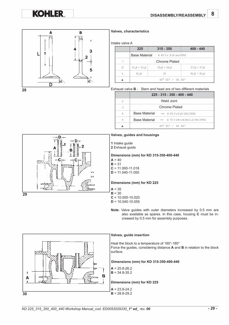
Valves, characteristics
IntakevalveA
ExhaustvalveB-Stemandheadareoftwodifferentmaterials
Valves, guides and housings
1 Intakeguide2 Exhaustguide
A=40B=31C=11.000-11.018D =11.040-11.055
A=35B=30C=10.000-10.020D =10.040-10.055
Note: Valve guides with outer diameters increased by 0.5 mm arealsoavailableasspares. In thiscase,housingCmustbe in-creasedby0.5mmforassemblypurposes.
Valves, guide insertion
Heattheblocktoatemperatureof160°-180°Forcetheguides,consideringdistance Aand Binrelationtotheblocksurface.
A=25.8-26.2B=34.8-35.2
A=23.8-24.2B=28.8-29.2
WeldJoint
ChromePlated
ChromePlated
BaseMaterial
BaseMaterial
BaseMaterial
KD 225_315_350_400_440 Workshop Manual_cod. ED0053029330_1° ed_ rev.00
Dimensions (mm) for KD 315-350-400-440
Dimensions (mm) for KD 225
Dimensions (mm) for KD 315-350-400-440
Dimensions (mm) for KD 225

31
32
33 34
8
A 530,6÷020,6 040,7÷520,7
B 000,6÷589,5 000,7÷589,6 000,7÷589,6
)B-A( 050,0÷020,0 550,0÷520,0
)B-A( 41,0
400-440225 315-350
Clearance
Limit
- 30 -
A 15,23÷05,23 10,73÷00,73 10,93÷00,93
B 26,23÷06,23 21,73÷01,73 21,93÷01,93
C 15,82÷05,82 10,33÷00,33 10,53÷00,53
D 26,82÷06,82 21,33÷01,33 21,53÷01,53
225 315-350 400-440
DISASSEMBLY/REASSEMBLY
Dimensions and clearance between guides and valve stems (mm)
Valves seats and valve seat bores
Dimensions (mm)
Note : Since the seats are supplied pre-finished, theymust not bemachinedafterhavingbeeninserted.
KD 225_315_350_400_440 Workshop Manual_cod. ED0053029330_1° ed_ rev.00
Valve seat lapping
Aftercuttingvalveseats,lapvalveseatswithfinelappingcompound.Thesealingsurface Sshouldnotexceed2mm.LoweringvalveforKD225-315-350(D=0.55÷0.85mm).LoweringvalveforKD400-440(D=0.35÷0.65mm).Wearlimit1.5mm.

37
35 36
38 39
40 41
8
510,96÷00.96 079,86÷559,86 60.0÷30.0
51.87÷00.87 079.77÷559.77 60.0÷30.0
510.28÷00.28 079.18÷559.18 60.0÷30.0
510,28÷00,28 079,18÷559,18 60.0÷30.0
510,28÷00,28 049,18÷529,18 90.0÷60.0
510,68÷00,68 079,58÷559,58 60.0÷30.0
225
315
350 - 350EPA
400
400EPA
440 - 440EPA
ClearanceØ PistonØ Cilinders
- 31 -
DISASSEMBLY/REASSEMBLY
Cylinder
Setaboregaugetozerowithacalibratedring.Checkdiameterat1, 2and3;repeattheoperationatthesamepointsafterturningtheboregauge90°.Ifwearexceedsthemax.givenvalueby0.05,borethecylinderandfitoversizepistonandrings.Seefig.40and41forcylinderdiametervalues.
Do notmanually hone the cylinder bore surfaceswith emeryclothorothermeans.
Cylinder roughness
Thecross-hatchpatternshouldbeatanangleof45°-55°;linesshouldbeuniformandclearinbothdirections.Averageroughnessmustrangebetween0.5mm1µm.Thecylindersurfacewhichcomesintocontactwithpistonringsshouldbemachinedwiththeplateaumethod.
Piston
Being of low expansion type, the piston allows small clearancesbetweenpistonandcylinderand,thus,oilconsumptionisreduced.Removecirclipsandpistonpin.Removepistonringsandcleangrooves.MeasurediameterQat theAdistancefromtheskirtbottom(A=12mm).Replace the piston and piston rings if wear on the diameter is 0.05mmmorethantheminimumvaluegiven(seetableinfig.40-41).
Note:Oversizepistonsof0.50and1.00mmareavailable.
Dimensions of pistons and cylinders, Logo
Logo can be found inside the piston
KD 225_315_350_400_440 Workshop Manual_cod. ED0053029330_1° ed_ rev.00

8
- 32 -
DISASSEMBLY/REASSEMBLY
KD 225_315_350_400_440 Workshop Manual_cod. ED0053029330_1° ed_ rev.00
42
8
04.0÷02.0
05.1÷00.1 05.0÷03.0
05.0÷52.0
05.0÷03.0
05.0÷03.0
05.0÷52.0
53.0÷02.0
05.1÷00.1 05,0÷03,0
05.0÷52.0
53.0÷02.0
05.1÷00.1 05.0÷03.0
05.0÷52.0
53.0÷02.0
05.0÷03.0
04.0÷02.0
- 33 -
DISASSEMBLY/REASSEMBLY
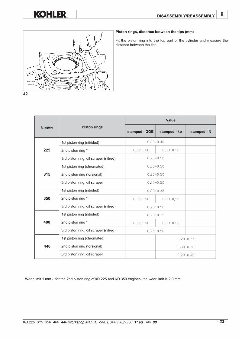
Piston rings, distance between the tips (mm)
Fit the piston ring into the top part of the cylinder andmeasure thedistancebetweenthetips.
225
315
350
400
440
1stpistonring(nitrided)
2ndpistonring*
3rdpistonring,oilscraper(nitred)
1stpistonring(chromated)
2ndpistonring(torsional)
3rdpistonring,oilscraper
1stpistonring(nitrided)
2ndpistonring*
3rdpistonring,oilscraper(nitred)
1stpistonring(nitrided)
2ndpistonring*
3rdpistonring,oilscraper(nitred)
1stpistonring(chromated)
2ndpistonring(torsional)
3rdpistonring,oilscraper
Piston ringsEngine
Value
stamped - GOE stamped - ko stamped - N
KD 225_315_350_400_440 Workshop Manual_cod. ED0053029330_1° ed_ rev.00
Wearlimit1mm-forthe2ndpistonringofkD225andKD350engines,thewearlimitis2.0mm.
43 44
45
46
47
8
A 511.0÷70.0 01.0÷70.0 11.0÷530.0 11,0÷70,0
B 80.0÷40.0 80.0÷50.0 90.0÷050.0 90,0÷50,0
C 70.0÷30.0 570.0÷40.0 780.0÷030.0 70,0÷30,0
225 315 350-400 440
- 34 -
DISASSEMBLY/REASSEMBLY
KD 225_315_350_400_440 Workshop Manual_cod. ED0053029330_1° ed_ rev.00
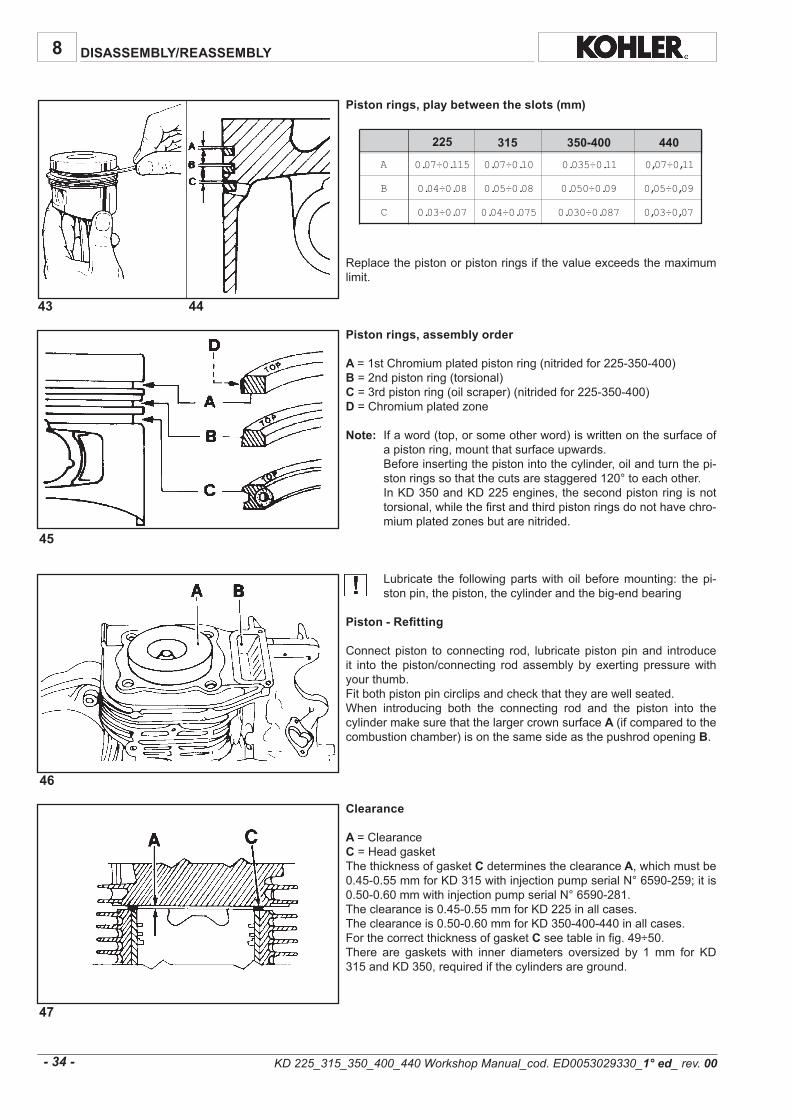
Piston rings, play between the slots (mm)
Replacethepistonorpistonringsifthevalueexceedsthemaximumlimit.
Piston rings, assembly order
A =1stChromiumplatedpistonring(nitridedfor225-350-400)B =2ndpistonring(torsional)C =3rdpistonring(oilscraper)(nitridedfor225-350-400)D =Chromiumplatedzone
Note: Ifaword(top,orsomeotherword)iswrittenonthesurfaceofapistonring,mountthatsurfaceupwards.
Beforeinsertingthepistonintothecylinder,oilandturnthepi-stonringssothatthecutsarestaggered120°toeachother.
InKD350andKD225engines,thesecondpistonringisnottorsional,whilethefirstandthirdpistonringsdonothavechro-miumplatedzonesbutarenitrided.
Lubricate the followingpartswithoil beforemounting: thepi-stonpin,thepiston,thecylinderandthebig-endbearing
Piston - Refitting
Connectpiston toconnecting rod, lubricatepistonpinand introduceit into thepiston/connecting rodassemblybyexertingpressurewithyourthumb.Fitbothpistonpincirclipsandcheckthattheyarewellseated.When introducing both the connecting rod and the piston into thecylindermakesurethatthelargercrownsurfaceA (ifcomparedtothecombustionchamber)isonthesamesideasthepushrodopeningB.
Clearance
A =ClearanceC =HeadgasketThethicknessofgasket Cdeterminestheclearance A,whichmustbe0.45-0.55mmforKD315withinjectionpumpserialN°6590-259;itis0.50-0.60mmwithinjectionpumpserialN°6590-281.Theclearanceis0.45-0.55mmforKD225inallcases.Theclearanceis0.50-0.60mmforKD350-400-440inallcases.ForthecorrectthicknessofgasketCseetableinfig.49÷50.There are gaskets with inner diameters oversized by 1mm for KD315andKD350,requiredifthecylindersareground.
49 50
48
8
054,0÷153,0 9,0 005,0÷563,0 1
055,0÷054,0 1 006,0÷005,0 1,1
056,0÷055,0 1,1 007,0÷006,0 2,1
057,0÷056,0 2,1
054,0÷563,0 9,0 005,0÷014,0 1
055,0÷054,0 1 006,0÷015,0 1,1
056,0÷055,0 1,1 007,0÷016,0 2,1
057,0÷056,0 2,1
004,0÷563,0 9,0 005,0÷014,0 1
005,0÷004,0 1 006,0÷015,0 1,1
006,0÷005,0 1,1 007,0÷016,0 2,1
007,0÷006,0 2,1
- 35 -
DISASSEMBLY/REASSEMBLY
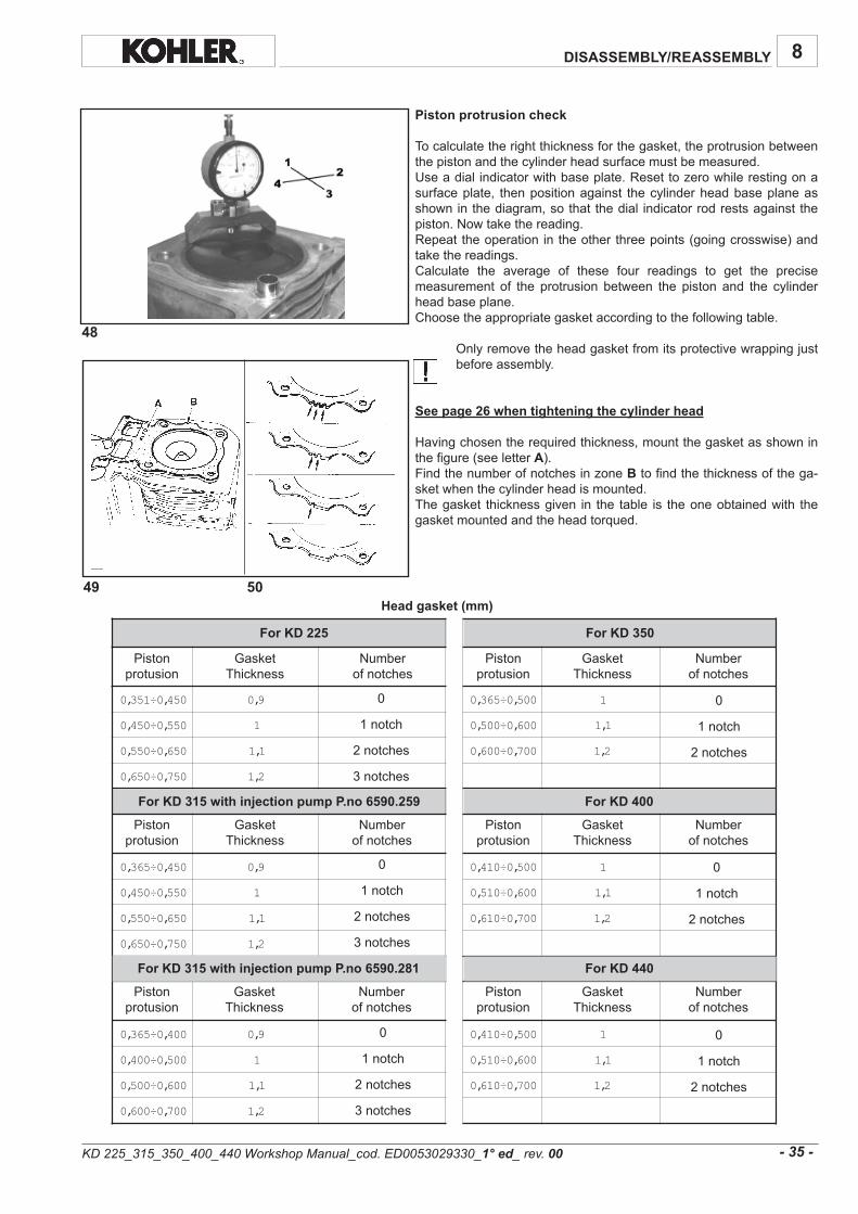
Piston protrusion check
Tocalculatetherightthicknessforthegasket,theprotrusionbetweenthepistonandthecylinderheadsurfacemustbemeasured.Useadialindicatorwithbaseplate.Resettozerowhilerestingonasurfaceplate, thenpositionagainst thecylinderheadbaseplaneasshowninthediagram,sothatthedial indicatorrodrestsagainstthepiston.Nowtakethereading.Repeattheoperationintheotherthreepoints(goingcrosswise)andtakethereadings.Calculate the average of these four readings to get the precisemeasurement of the protrusion between the piston and the cylinderheadbaseplane.Choosetheappropriategasketaccordingtothefollowingtable.
Onlyremovetheheadgasketfromitsprotectivewrappingjustbeforeassembly.
See page 26 when tightening the cylinder head
Havingchosentherequiredthickness,mountthegasketasshowninthefigure(seeletterA).FindthenumberofnotchesinzoneBtofindthethicknessofthega-sketwhenthecylinderheadismounted.Thegasket thicknessgiven in the table is theoneobtainedwith thegasketmountedandtheheadtorqued.
Head gasket (mm)
0
1notch
2notches
3notches
0
1notch
2notches
Pistonprotusion
GasketThickness
Numberofnotches
Numberofnotches
GasketThickness
Pistonprotusion
Pistonprotusion
GasketThickness
Numberofnotches
Numberofnotches
GasketThickness
Pistonprotusion
0
1notch
2notches
3notches
0
1notch
2notches
0
1notch
2notches
3notches
0
1notch
2notches
Numberofnotches
GasketThickness
Pistonprotusion
Numberofnotches
GasketThickness
Pistonprotusion
KD 225_315_350_400_440 Workshop Manual_cod. ED0053029330_1° ed_ rev.00
For KD 315 with injection pump P.no 6590.259
For KD 225 For KD 350
For KD 400
For KD 315 with injection pump P.no 6590.281 For KD 440

51
52
53
54
8
A 30,001÷079,99 30,011÷079,901 30,521÷79,421
B 020,02÷010,02 020,22÷010,22 020,32÷010,32
D 000,02÷599,91 000,22÷599,12 000,32÷599,22
)D-B( 520,0÷010,0
)D-B( 50,0
225 315 350 400-440
- 36 -
DISASSEMBLY/REASSEMBLY
Clearance
Limit
KD 225_315_350_400_440 Workshop Manual_cod. ED0053029330_1° ed_ rev.00
When remounting thebig-endbearings, remember to thorou-ghlycleanthepartsandgenerously lubricatethemtopreventseizurewhentheengineisstartedupforthefirsttime
Connecting rod
Demount the connecting rodandproceedwith the following inspec-tions.Thebig-endcapandbig-endbearthesamenumbers.Whenremounting,mount thecapfromthesamesideas inCof thefigure.TightentheKD225boltstoa23Nmtorquevalue.Tightentheboltstoa30NmtorquevalueforKD315-350-400-440.
Connecting rod, piston pin
Note: The connecting rod has no insert bearings. See fig. 62 forconnectingrodbigenddiameter.
Connecting rod alignement
Useadialgaugeasshowninthefigure.Checkthataxesarealignedusingthepistonpin;axialmisalignmentA=0.015;limit0.03mm.
Crankshaft end play
Securetheenginetoametalbaseortable.Useadial indicatorwithcolumnandmagneticbaseplate.Placethestylusonthecrankshaft.Movethedrivingshaftbackandforthontheflywheelside.Endplayshouldbe0.05-0.25mm;itisnotadjustable.

57
55 56
58
59 60
8
- 37 -
DISASSEMBLY/REASSEMBLY
Drive shaft oil seals
Oilretainer 1islocatedinthegearcoveronthetimingsidewhilere-tainer2 islocatedinthecrankcaseontheflywheelside.Arrowsapointtothecrankshaftdirectionofrotation.Press them into their seatsbyexertinguniformpressure throughouttheirfrontsurface.
Drive shaft, lubrication ducts, bore thread on flywheel side and p.t.o.
RemoveplugCandcheckthatthelubricationductisperfectlyclean.Closewithanewplugcheckingforpropersealing.A =M14x1.5(turncounterclockwise)B =M8x1.25(withstandardshaft)
Whenthecrankpinandmainjournalareground,valuesR andR1mustbeobtainedagaintopreventthedriveshaftfrombre-aking.
Drive shaft, connection radius
Radius R thatjoinsthecrankpintothesupportsis2.8-3.2mm.RadiusR1 thatjoinsthemainjournaltothetiminggearis0.5mm.
Drive shaft, main journal/crankpin diameter, gear cover bearing inside diameter on timing side
Use an outsidemicrometer for themain journal and an inside boregaugeforthegearcoverbearingonthetimingside.
KD 225_315_350_400_440 Workshop Manual_cod. ED0053029330_1° ed_ rev.00
Awarpedoil retainermayallowthe introductionofair into theenginethuscausingcrankcaseventilationproblems.UsegenuineoilretainerswiththeKOHLERlogo(see B).

61
62
8
M579,43÷959,43 579,43÷959,43 579,93÷959,93
A 310,53÷200,53 310,53÷200,53 310,04÷200,04
B 000,43÷489,33 000,83÷489,73 000,04÷489,93
L 652,53÷042,53 652,53÷042,53 652,04÷042,04
C 000,53÷489,43 000,53÷489,43 000,04÷489,93
D000,82÷769,72 000,82÷769,72 000,03÷769,92
225 400-440315-350
D 640,43÷030,43 640,83÷030,83 640,04÷030,04
E 050,53÷030,53 050,53÷030,53 050,04÷030,04
G 610,54÷000,54 610,54÷000,54 910,35÷000,35
H 000,53÷889,43 000,53÷889,43002,53÷481,53 000,04÷889,93
I 612,53÷002,53 612,53÷002,53 612,04÷002,04
)B-D( 260,0÷30,0 260,0÷030,0 260,0030,0
)B-D( 021,0 021,0 021,0
)C-E( 660,0÷30,0 660,0÷030,0 660,0030,0
)H-A( 520,0÷200,0 420,0÷200,0 420,0÷200,0
)G-F( 650,0÷510,0 650,0÷510,0 650,0÷510,0
)I-L( 650,0÷420,0 650,0÷420,0 650,0÷420,0
225 400-440315-350
225 400-440315-350
225 400-440315-350
- 38 -
DISASSEMBLY/REASSEMBLY
oilsealworkingarea
oilsealworkingarea
Crankshaft - journal diameter (mm)
The undersizes for the crankpin and main journal are 0.25,0.50and1mm.
The gearsmust bemountedwith the right tools so that theycanbecorrectlytimed.Thegearsshouldnotthereforebedemounted.Onlythecompleteshaftisavailableasaspare.
Drive shaft - Main bearing inside diameter, connecting rod big end, crankshaft bearing and timing control gear and balancer - Clearance and interference between the corresponding journals
Dimensions (mm) (see also fig. 61)
Clearance (mm)
Interference (mm)
Availability of bearings
Main bearings are available at their nominal value orundersized0.25,0.50and1.0mm.Connecting rodsareavailablewithbigendatnominalvalueorundersized0.25and0.50mm.
Limit
KD 225_315_350_400_440 Workshop Manual_cod. ED0053029330_1° ed_ rev.00

63
64 65
66
67
8
A 474,91÷954,91 089,12÷959,12 489,71÷669,71
B 489,51÷759,51
C 810,61÷000,61
D 125,91÷005,91 120,22÷000,22 810,81÷00,81
)A-D( 260,0÷620,0 260,0÷020,0 250,0÷610,0
)A-D( 021,0 001,0
)B-C( 160,0÷610,0
)B-C( 021,0
225 400-440315-350
H 03,03÷52,03 03,03÷52,03 00,23÷59,13 50,23÷00,23
H1 08,53÷57,53 08,53÷57,53 08,53÷57,53 51,63÷01,63
H2 07,33÷56,33 01,53÷50,53 07.33÷56,33 51,53÷01,53
225 315-350 350 EPA 400-440
- 39 -
DISASSEMBLY/REASSEMBLY
Camshaft
Components:1 Journal,gearcoverontimingside2Gear3Exhaustlobe4Injectionlobe5Fuelpumpeccentric6 Intakelobe7Journal,crankcaseside
Camshaft journals and bore
Useacomparatorforinteriors
Dimensions of camshaft journals and bore (mm)
Cam height (mm)
Note:Replacecamshaftifcamwearexceedstheminimumgivenva-lueofH,H1andH2by0.1mm.
Limit
Limit
KD 225_315_350_400_440 Workshop Manual_cod. ED0053029330_1° ed_ rev.00

68
68b
68a
68c
A
B
8
- 40 -
DISASSEMBLY/REASSEMBLY
Camshaft timing
Fitcamshaftbyaligningmarks'AwithmarkDonthecrankshaft.
itconsistsofadeviceonthecamshaftwhichliftstheintakevalveincaseofastartupinreversedirectionwithrespecttonormalrotation.
Duringnormaloperation,thetappetovercomesthespringresistancewhilepassingonthesystemanddecompressiondoesnotoperate.
Incaseofastartup in reversedirection, theantireversesystem liftsthevalveasthetappetpassesby.Startupisthusinhibited.
Note:Checktheantireversesystemforwear,andmakesureitiskeptin the rest position by the return spring, as shown in picture68c.Verifythat inthisconditiontheclearancebetweenweightAandsurfaceBis1mm.
KD 225_315_350_400_440 Workshop Manual_cod. ED0053029330_1° ed_ rev.00
Camshaft – Antireverse system KD 400-440

69 70
71
72
8
- 41 -
DISASSEMBLY/REASSEMBLY
Automatic decompression
With the engine at a standstill and up to a rate of about 300RPM,spring1,actingonweights2and3via lever4andpin5,keeps theexhaustvalveopenduringthecompressionphasealso.Once the engine exceeds the 300RPM rate,weights1 and2 keeppin5intheholdpositionowingtotheactionofthecentrifugalforce.Inthisposition,cam6canregularlycontroltheexhaustvalvethankstoaridgeonthepinitself.Sincethereisthennocompressioninthecylinder,theenginewillea-silystartwhentheself-winderisused.
Camshaft end play
Perform this checkbeforefittingcylinderheadand tappets includingtheinjectiontappets.Temporarilyfitcamshaft1completewithwasher;tightengearcover2to25Nm.Checkendplaybymovingthecamshaftbackandforthusingasuita-bletool;theendplayvalueis0.10÷0.25mmandisnotadjustable.
Dynamic balancer (on request)
Thedynamicbalancerissupportedbytwoidenticalballbearingshou-sedinthecrankcaseandinthegearcoveronthetimingsiderespec-tively.1isthereferencepointfortimingwiththecranksaftgear(seebelow).
Dimensions(mm):A =14.983-14.994B =14.99-15.00C =34.89-35.00D=34.958-34.983(bearinghousingdiameteroncrankcaseandgear
coverontimingside).
KD 225_315_350_400_440 Workshop Manual_cod. ED0053029330_1° ed_ rev.00

8
- 42 -
DISASSEMBLY/REASSEMBLY
KD 225_315_350_400_440 Workshop Manual_cod. ED0053029330_1° ed_ rev.00

74 75
73
8
- 43 -
DISASSEMBLY/REASSEMBLY
Dinamic balancer timing
Positioncrankshaftasshowninthefigure.Introduce the dynamic balancer so that timing mark 1 engagesbetweenteeth2 ofthecrankshaftgear.
Valve timing check
Removethetankandconveyortoaccesstheflywheel.Carry out the inspections on the drive shaft. The values given aremeasuredonthecircumferenceoftheflywheel.Adjustthevalveplayasindicatedonthenextpage.Reset the comparator on the cap of intake valve 1. Turn the driveshaft in thespinningdirectionandfindα (pointatwhich the intakevalvestartstoopeninrelationtotopdeadcenterA)and β (pointatwhichtheintakevalveshutsafterbottomdeadcenter B)seefig.77-78.Proceed ina similarwaywith theexhaust valve, checkingγ (pointatwhichtheexhaustvalveopens)andδ (pointatwhichtheexhaustvalveshuts).
KD 225_315_350_400_440 Workshop Manual_cod. ED0053029330_1° ed_ rev.00

78
77
DISASSEMBLY/REASSEMBLY8
- 44 -
Timing angles for operation (0.15 valve play).
α = 6°beforeAcorrespondingto12mmβ = 22°after Bcorrespondingto44mmγ =58°beforeBcorrespondingto116mmδ =10°after Acorrespondingto20mm.
Valuesmeasuredonthecircumferenceof theflywheelD=230(onedegreecorrespondsto2mm).
α = 10°beforeAcorrespondingto20.09mmβ = 42°after Bcorrespondingto87.78mmγ =58°beforeBcorrespondingto121.22mmδ =10°after Acorrespondingto20.9mm.
Valuesmeasuredonthecircumferenceof theflywheelD=240(onedegreecorrespondsto2.09mm).
Timing angles for inspection (0.65-0.70 valve play).
α = 7°afterAcorrespondingto14mmβ = 9°after Bcorrespondingto18mmγ =45°beforeBcorrespondingto90mmδ =3°beforeAcorrespondingto6mm.
Valuesmeasuredonthecircumferenceof theflywheelD=230(onedegreecorrespondsto2mm).
α = 1°afterAcorrespondingto2.09mmβ = 31°after Bcorrespondingto64.79mmγ =45°beforeBcorrespondingto94.05mmδ =3°before Acorrespondingto6.27mm.
Valuesmeasuredonthecircumferenceof theflywheelD=240(onedegreecorrespondsto2.09mm).
KD 225_315_350_400_440 Workshop Manual_cod. ED0053029330_1° ed_ rev.00
For KD 225
For KD 315 - 350
For KD 225
For KD 315 - 350

79
80
81
DISASSEMBLY/REASSEMBLY 8
- 45 -
Speed governor
Components:1Spoolspacer2Spool3Weights4Spoolguide5Gear6 Oilpumpdrivingshaft7Circlip8Thrustring
Speed governor removal
Spoolguide1hasretainersoneendwhichpreventspool2fromslip-pingout.To remove the speed governor use a suitable tool to slightlywidenthetwoteeth.
Refitting gear cover on timing side
Propersealingbetweengearcoverandcrankcaseisensuredbytheliquidsealant"Loctite5205".Carefullycleanthetwosealingsurfacesandspreadthesealantuniformly.Tightenscrewsto23Nm.
Wait3 hoursbeforestartingtheengine.
KD 225_315_350_400_440 Workshop Manual_cod. ED0053029330_1° ed_ rev.00

82
9
- 46 -
LUBRICATION SYSTEM
Theenginecanbedamagedifallowedtooperatewithinsufficientoil.Itisalsodangeroustoaddtoomuchoilbecauseitscombustionmayleadtoasharpincreaseintherotationspeed.Usesuitableoilinordertoprotecttheengine.Nothingmorethanlubricationoilcaninfluencetheperformancesandlifeofanengine.Useofaninferiorqualityoilorfailuretoregularlychangetheoilwillincreasetheriskofpistonseizure,willcausethepistonringstojamandwillleadtorapidwearonthecylinderliner,thebearingsandallothermovingparts.Enginelifewillalsobenotablyreduced.Theoilviscositymustsuittheambienttemperatureinwhichtheengineoperates.
Oldengineoilcancauseskincancerifrepeatedlyleftincontactwiththeskinandforlongperiodsoftime.Wearprotectiveglovestoavoidtouchingusedoil.Ifcontactwiththeoilisunavoidable,youareadvisedtowashyourhandswithsoapandwaterassoonaspossible.Disposeofoldoilinthecorrectwayasitishighlypolluting.
Components:
1)Oilfillcap 6)Oildrainplug 11)Oilintakefilter2)Safetyvalve 7)Metalfilterelement3)Rodjournal 8)Mainjournal4)Pressurecontrolvalve 9)Oilfilter5)Pressureswitch 10)Oilpump
KD 225_315_350_400_440 Workshop Manual_cod. ED0053029330_1° ed_ rev.00
KD 225 - 315 - 350 LUBRICATION SYSTEM AND BREATHER RECIRCULATION SYSTEM

9
83
- 47 -
LUBRICATION SYSTEM
Components:
1)Oilfillcap 6)Oildrainplug 11)Oilintakefilter2)Safetyvalve 7)Metalfilterelement 12)Pushrods3)Rodjournal 8)Mainjournal 13)Hydraulictappets4)Pressurecontrolvalve 9)Oilfilter 14)Calibratedunion5)Pressureswitch 10)Oilpump
KD 225_315_350_400_440 Workshop Manual_cod. ED0053029330_1° ed_ rev.00
KD 400-440 LUBRICATION SYSTEM AND BREATHER RECIRCULATION SYSTEM

84
85
88 89
86 87
9
- 48 -
LUBRICATION SYSTEM
KD 225_315_350_400_440 Workshop Manual_cod. ED0053029330_1° ed_ rev.00
Oil pump
Components:
1 Cover2Shaft3Key4Pin5Internalrotor6Externalrotor
Oilpumpdeliveryat3000rpmis5.8l/min.
Oil pump - Clearance between rotors
Measureclearanceasshowninthefigure;themax.valueis0.13mm;wearlimit0.25mm.
Oil pressure regulation valve
Components for KD 315 and KD 350:1 Spring 2 Valve 3 PlugFreelengthA ofthespringis27.50-27.75mm.
Components for KD 225:4 Ball 5 Spring 6 PlugFreelengthA ofthespringis23.50-24.50mm.
Components for KD 400-440:7 Plunger 8 Spring 9 Washer10 Cup 11 SnapringFreelengthA ofthespringis25,50÷25,75mm.
Note: IfAis1mmlessthanthegivenvalue,replacethevalve. Valvesettingisnotadjustable.
Internal strainer
Theoilpick-upstrainerismadeofnylon66.Itsdegreeoffiltrationis500µm.
Dimensions(mm):A =M16x1.5B =64C=102D=12

92
90 91
93
9
- 49 -
LUBRICATION SYSTEM
KD 225_315_350_400_440 Workshop Manual_cod. ED0053029330_1° ed_ rev.00
Oil filter
Filtercomponents:KD 315/350
1 Seal2Adhesive3Endcap4 Filteringmaterial5 Plate
Dimensionmm:A =26.5B=18C=88.5D =67.5E =8.5
Characteristics:Usefulfilteringarea=75cm2
Degreeoffiltration=50µm.Theby-passvalveissetat0.6-0.8bar.
Filtercomponents:KD 225
7 Rubberpad8Uppercover9Filterelement10 Lowercover
Dimensionmm:A =19.0-19.3B=12.5C=83.0-83.5
Characteristics:Usefulfilteringarea≥75cm2
Degreeoffiltration=40-60µm.
Seepage18forthereplacementfrequencies.
Oil pressure check
Whenassemblyoperationsarecompletedfillenginewithoilandfuel;connecta10barpressuregaugetotheoilfilterfitting.Starttheengineandcheckpressureasafunctionoftheoiltempera-ture(seebelow).
Calibrated pipe for lubrication of hydraulic tappets
Thepipe is fitted to thehydraulic tappetsoil line (see fig. 83, detail11).If the calibrated hole is clogged, the tappets are not sufficientlylubricated,valveclearanceisthereforeincreasedandtheenginemaybenoisier.If thediameterof thecalibratedpipeis largerthantheonesgiveninpicture93, thepressureexertedbythehydraulic tappetsmaycausethevalvestoremainopenevenduringthecompressionphase.

94
95
9
- 50 -
LUBRICATION SYSTEM
Oil pressure curve at idle speed
Thecurveisobtainedattheoilfilterportwithenginerunningatacon-stantspeedof1200r.p.m.inno-loadconditions;pressureisgiveninbarandtemperatureincentigrades.The curve represents theminimumpressure value while themaxi-mumvalueis5bar.
Oil pressure curve at full speed
Thecurveisobtainedattheoilfilterportwithenginerunningat3000r.p.m. at theN power; pressure is given in bar and temperature incentigrades.The curve represents theminimumpressure valuewhile the maxi-mumvalueis5bar.
Note:Aftertherunning-inperiodthelubemax.temperatureshouldbelessthantheroomtemperature+95°C.
KD 225_315_350_400_440 Workshop Manual_cod. ED0053029330_1° ed_ rev.00

96
97
9
- 51 -
LUBRICATION SYSTEM
Components:
1 Tank2 Returntube3 Fuelfilter4 Injectionpump5 Injectorleak-offline6Injector7 Highpressureline8Returntube
1 Tank2 Injectorleak-offline3 Injector4 Highpressureline5 Returntube6 Returntube7Dieselfuelfilter8 Fuelpipe9T-connector10Reduction11Injectionpump
KD 225_315_350_400_440 Workshop Manual_cod. ED0053029330_1° ed_ rev.00
Fuelling/injection circuit for KD 315-350-400-440
Fuelling/injection circuit for KD 225

98
100
99
10
- 52 -
FUEL SYSTEM
A =7.3B=3.8C =1.5D=42H=75
Characteristics:Filteringarea≥390cm²Filtrationlevel≤7µmSeepage18forfuelfilterreplacement
1 Rubberretentionring2PRVcover3 SCPradialunit4PRVcover5Segment
Characteristics:Filteringarea215cm2
Filtrationlevel7µmSeepage18forfuelfilterreplacement
Feed pump (optional)
A feed pump is usually requested when the tank is not supplied inconjunctionwiththeengine.Thepumpisthediaphragmtypeandisoperatedbyacamshaftec-centricthroughadriverod.Tightenscrewsto15Nm.
Characteristics:At 2000 rpmof the camshaft, theminimumdeliveryis40l/h,whiletheautomaticadjustmentpressureis0.5÷0.7bars.
KD 225_315_350_400_440 Workshop Manual_cod. ED0053029330_1° ed_ rev.00
Fuel filter KD 225 (version with internal filter in tank)
Fuel filter KD 225-315-350-400-440

101
102
103 104
10
- 53 -
FUEL SYSTEM
Fuel pump, drive rod protrusion
Components:
1Fuelpump2Crankcase3Driverod4Eccentric
Checkwhileeccentric4isatrest(lowestpointoftravel).Protrusion A ofdriverod3is1.5-1.9mm;itisnotadjustable.
Injection pump
ThisisofthesimplifiedQLCtype;itishousedinthecrankcaseandiscontrolledbythecamshaftviatappets.
Injection pump fitting in the crankcase
Fittappets3 sothatscrew6 isintroducedintoguide4.Tighten screw6 to 9Nmand check that the tappet is free tomovedownwards.Fitpad 2intothetappetsothatrecessBpointsdownwardsasshowninthefigure.Fittheinjectionpumpintothecrankcasecompletewithgasket(C)po-sition8ingflowcontrol1 in the forkof lever5 whichshouldbe in themaximumflowposition.
Whenremovingtheinjectionpumpfromitshousingmakesurethatspacer2 isnotdroppedintotheoilsump; injectionpumpoperationwillbeimpairedufthespacerisnotinstalled.
KD 225_315_350_400_440 Workshop Manual_cod. ED0053029330_1° ed_ rev.00
Driverodlength=58-58.2mmforKD225Driverodlength=65.8-66.0mmforKD315/350Driverodlength=61,4÷61,6mmforKD400/440
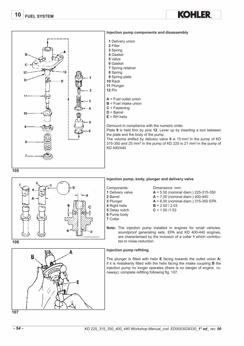
107
105
106
10
- 54 -
FUEL SYSTEM
KD 225_315_350_400_440 Workshop Manual_cod. ED0053029330_1° ed_ rev.00
Injection pump components and disassembly 1 Deliveryunion 2Filler3 Spring 4Gasket5Valve6Gasket7Springretainer8Spring9 Springplate10Rack11Plunger12Pin
A=FueloutletunionB =FuelintakeunionC=FasteningD=BarrelE=RHhelix
Demountincompliancewiththenumericorder.Plate9 isheldfirmbypins 12.Leverupby insertingatoolbetweentheplateandthebodyofthepump.Thevolumeshiftedbydeliveryvalve5 is15mm3in thepumpofKD315-350and25mm³inthepumpofKD225is21mm3inthepumpofKD400/440
Injection pump, body, plunger and delivery valve
Components: Dimensionsmm:1 Deliveryvalve A=5.50(nominaldiam.)225-315-3502 Barrel A=7,00(nominaldiam.)400-4403Plunger A=6,00(nominaldiam.)315-350EPA4 Righthelix B=2.00/2.035Delaynotch C=1.50/1.536Pumpbody7 Collar
Note: The injection pump installed in engines for small vehicles,soundproof generating sets, EPA and KD 400-440 engines,arecharacterisedbytheinclusionofacollar1whichcontribu-testonoise-reduction.
Injection pump refitting
Theplunger is fittedwith helixE facing towards the outlet unionA;if it ismistakenlyfittedwiththehelixfacingtheintakecouplingBtheinjectionpumpnolongeroperates(there isnodangerofengineru-naway);completerefittingfollowingfig.107.

111 112
109 110
108
2 1
3
10
- 55 -
FUEL SYSTEM
Injection pump non-return valve
Theexhaustunionhasanon-returnvalveA.Thepurposeofthisval-veistoimprovetheinjectionphasebyexpellingtheairinthefuelandpreventingitfrombeingsuckedinbythepumpduringtheintakepha-se.Thisalsoensuresthattheenginestopspromptlyassoonasthestoppingdeviceisactivatedbymeansofthesolenoidvalve.
Outlet fitting components for 315-350 EPA E 400-440 engines
1) Outletfitting2) BallØ1/8"3) Threadeddowel
Donotcutthetubelongitudinallybecauseyoumightdamagetheunion.
Injection pump, Rilsan tube removal
CutnylontubeatA.Removetheportionof the tubewhich isstillconnected to theunionusingcommonpliers.Pinchthenylontubewithoutimpairingthesea-lingpropertiesofunion(seefigure).Re-cycle thesamefeeding tube if theremaining lengthallows it; re-placeifnot.
Injection pump, Rilsan tube refitting
TheoutlettubeismadeofnylontypeRilsan;itisconnectedtothesu-itableinjectionpumpunionbymeansofspecialpliers(Ser.No.7104-1460-023)andaplastic-headhammer(seefigure).
KD 225_315_350_400_440 Workshop Manual_cod. ED0053029330_1° ed_ rev.00
KD225-315-350
KD315-350 EPA
400-440
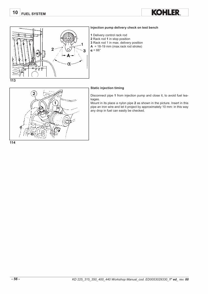
113
114
10
- 56 -
FUEL SYSTEM
Injection pump delivery check on test bench
1 Deliverycontrolrackrod2Rackrod1 instopposition3Rackrod1inmax.deliverypositionA=18-19mm(max.rackrodstroke)α=66°
Static injection timing
Disconnectpipe1frominjectionpumpandcloseit,toavoidfuellea-kages.Mountinitsplaceanylonpipe2asshowninthepicture.Insertinthispipeanironwireandletitprojectbyapproximately10mm:inthiswayanydropinfuelcaneasilybechecked.
KD 225_315_350_400_440 Workshop Manual_cod. ED0053029330_1° ed_ rev.00

115
10
mmC/B
44÷04 64÷24 32÷12
5,23÷92 43÷03 71÷51
83÷5,43 04÷63 02÷81
05÷64 25÷84 52÷32
44÷04 64÷24 22÷02
04÷63 24÷83 02÷81
84,92 31
59,42 11
53,82 5,21
59,42 11
57,13 41
12,72 21
α
- 57 -
FUEL SYSTEM
Static injection lead test on flywheel
Fill the tankandmakesure that the fuel isnotmorethan10-15cmabovethetester.Settheflowgovernorleveroftheinjectionpumpinthestoppositionandlockitthere.Turntheflywheelintheenginerotationdirection.proceedslowlydu-ringthecompressionphase.Thefuelthatflowsfromtube2willtendtodiminish.Stopassoonasitcreasestodrip(onedropoffuelevery30-40secondsistolerated):thisisthestaticinjectionlead.MakesurethatBcoincideswithA.Seefig.117-118ifB doesnotcoincidewithA.
Useatemporarytankiftheengineisnotfittedwithone.Hereagain,itisessentialtomakesurethatthefuellevelisnomorethan10-15cmabovetheinjectionmpump.
References on the flywheelA=ReferenceoffixedTDConcrankcaseB=InjectionleadreferenceontheflywheelC=TDCreferenceonflywheelα =Referenceindegreesbetween BandC.WhenB coincideswith A,thepistonisinthestaticinjectionleadposition.When C coincideswithA,thepistonisattopdeadcenter.
Motor type withexternalØflywheel
220
withexternalØflywheel
230
withexternalØflywheel
240
withexternalØflywheel
260
KD 225_315_350_400_440 Workshop Manual_cod. ED0053029330_1° ed_ rev.00
KD225standard
KD225recordedupto1500[rpm]
KD225recordedfrom1500to2200[rpm]
KD315/350standardandminivecture
KD315/350Soundproofgeneratingsets
KD315/350recordedto1500[rpm]
KD400recordedto3600[rpm]
KD400recordedto3000[rpm]
KD400EPArecordedto3600[rpm]
KD400EPArecordedto3000[rpm]
KD440recordedto3600[rpm]
KD440recordedto3000[rpm]
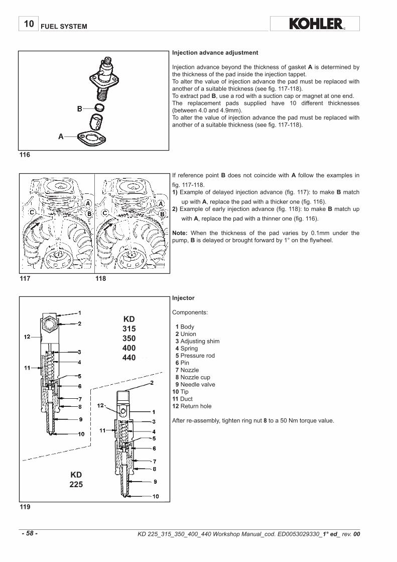
116
117 118
10
119
- 58 -
KD315350400440
KD225
FUEL SYSTEM
Injection advance adjustment
InjectionadvancebeyondthethicknessofgasketA isdeterminedbythethicknessofthepadinsidetheinjectiontappet.Toalterthevalueofinjectionadvancethepadmustbereplacedwithanotherofasuitablethickness(seefig.117-118).ToextractpadB,usearodwithasuctioncapormagnetatoneend.The replacement pads supplied have 10 different thicknesses(between4.0and4.9mm).Toalterthevalueofinjectionadvancethepadmustbereplacedwithanotherofasuitablethickness(seefig.117-118).
If referencepointBdoesnotcoincidewithA follow theexamples infig.117-118.1)Exampleofdelayedinjectionadvance(fig.117):tomakeB match
upwithA,replacethepadwithathickerone(fig.116).2) Exampleofearlyinjectionadvance(fig.118):tomakeBmatchup
withA,replacethepadwithathinnerone(fig.116).
Note: When the thickness of the pad varies by 0.1mm under thepump,Bisdelayedorbroughtforwardby1°ontheflywheel.
Injector
Components:
1Body2 Union3 Adjustingshim4 Spring5 Pressurerod6Pin 7Nozzle8 Nozzlecup9 Needlevalve10Tip11Duct12Returnhole
Afterre-assembly,tightenringnut8toa50Nmtorquevalue.
KD 225_315_350_400_440 Workshop Manual_cod. ED0053029330_1° ed_ rev.00

121
120
10
A 5,4 5,4 5,4 5,4 5,4 5,4 5,4 5,4 5,4
B 71,0x4 02,0x4 141,0x5 22,0x4 141,0x5 951,0x5 051,0x5 661,0x5 561,0x5
5,0 6,0 8,0 6,0 8,0 5,0 8,0 5,0 8,0
aaaaa °061 °061 °551 °061 °541 °061 °061 °061 °551
÷01,051,0
÷01,051,0
÷571,0522,0
÷521,0571,0
÷571,0522,0
÷573,0524,0
÷573,0524,0
÷573,0524,0
÷573,0524,0
C³mm63,0 ³mm63,0 ³mm0 ³mm63,0 ³mm0 ³mm91,0 ³mm0 ³mm91,0 ³mm0
4±412 4±412 6±042 4±412 6±042 4±002 4±952 4±002 6±042
- 59 -
FUEL SYSTEM
Leakage time (waste)
Pressuremustdropfrom150to100barsinaspanofnotlessthan8secondsandnotmorethan30.
Seatseal
Nozzletipwet.Pressuremustbekept20barsbelowtheopeningpressurefor10seconds.After this time,dampnessonthenozzletip isacceptable,andmaybe identifiedbytouchingwithadryfinger.Onlyadropofdampnessisacceptableandnotalargethickpatchwhichwouldindicatealeak.
Injector calibration
Connect the injector to a hand pump and adjust if necessary,modifyingthethicknessabovethespring.When the spring is replaced, calibration must be carried out at apressure higher than 10 bars to counterbalance adjustments whilerunning.
Spraying and opening pressure
With the pressure gauge closed, press hard on the hand pump atleast10times.Open thepressuregaugeandpressdownon thepumponceeverysecond,whilekeepingacheckonthesprayingprocessandpressure.Theopeningpressuremust lie between the two valuesgiven in thetable.Jetsmustbeuniformandwelldistributed.
*Thesevaluesapplytonewinjectorandallowforlooseningofupto10%afterbreaking-inperiod
Nozzles
Theset-upbetweentheneedleandtheguidemust leavetheneedlefreetofallandmerelyasaresultof itsownweight,whenlifted7mmfromitsseatandrotatedindifferentdirections,withthenozzlekeptata45°angle.Rotationoftheneedlemustbecompletelysmoothanduninhibitedbyobstaclesandmalformations.Moreover,onbeingsqueezedagainstitsseat,itmustfallfreely,whenthenozzleisinverted.Thetestmustbecarriedoutafterrinsingboththeneedleandnozzlewith trichloroethane and wetting with filtered SHELL CALIBRATIONFLUID“C”oil.
n°andØofholes
holelenght
pinheight
sumpvolume
pressure(bar)*
KD 225_315_350_400_440 Workshop Manual_cod. ED0053029330_1° ed_ rev.00

10
- 60 -
FUEL SYSTEM
KD 225_315_350_400_440 Workshop Manual_cod. ED0053029330_1° ed_ rev.00

122
123
124
11
- 61 -
ELECTRICAL SYSTEM
12V, 12A electric ignition diagram
Components:1Alternator2Startermotor3 Voltageregulator4 Battery5 Pressureswitch6Oilpressurelight7Keyswitch8Batterycharginglight
Alternator
Components:1Ringgear2 Flywheel3Rotor4Stator
Fixingscrewsmustbetightenedto1.2Nm.
Note:The rotor ismade up by a plastoferrite ringwhich is fixed toflywheelwhilethestatorismountedonthecrankcase.
Alternator battery charger graph (12V, 12A)
Thistesthasbeencarriedoutafterthermalstabilizationat20°Cfor2minutesat3000r.p.m.withconstantbatteryvoltageof12.5V.The value of the power supplied with reference to the curve maychangeinarangebetween+10%and-5%.
KD 225_315_350_400_440 Workshop Manual_cod. ED0053029330_1° ed_ rev.00
Note: The battery,which is not supplied byKOHLER, should have12Vnominalvoltageratingandacapacityofnotlessthan44Ah/210Amp.offastdischargeintensity.

125
127
126
11
- 62 -
ELECTRICAL SYSTEM
24V, 9A alternator battery recharging curve
12V, 30A alternator battery recharging curve
Thetestwasconductedafterheatstabilizingat20°C.The value of the current delivered in relation to the curve may besubjectedtoavariationofbetween+10%and-5%.
Voltage regulator
12V,12A:forstandardalternatorswith3outputwires12V,30A:for12V,20Aalternatorswith2outputwires24V,9A:for24V,9Aalternatorswithtwooutputwires
Thetabsareindifferentsizestopreventincorrectconnections.
Tabdimensionsmm
Width Thickness
~ 6.35 0.80
R 9.50 1.12
+ 9.50 1.12
LE 4.75 0.50
0/0 6.35 0.80
W 4.75 0.50
KD 225_315_350_400_440 Workshop Manual_cod. ED0053029330_1° ed_ rev.00

128
129
11
- 63 -
ELECTRICAL SYSTEM
12V electric starter diagram with voltage regulator built into the ignition panel
Components:
1 Alternator2 Startermotor4 Battery5 Pressureswitch6 Solenoidvalve7 Ignitionswitch
12V electric ignition layout with motor protection (optional)
Components:
1 Alternator2 Startermotor4 Battery5 Pressureswitch6 Solenoidvalve7 Ignitionswitch8 Panel
KD 225_315_350_400_440 Workshop Manual_cod. ED0053029330_1° ed_ rev.00
Note: Thebattery,which is not supplied byKOHLER, should have12Vnominalvoltageratingandacapacityofnotlessthan44Ah/210Amp.offastdischargeintensity.
Note: Thebattery,which is not supplied byKOHLER, should have12Vnominalvoltageratingandacapacityofnotlessthan44Ah/210Amp.offastdischargeintensity.

130
11
- 64 -
ELECTRICAL SYSTEM
Diagram of electric starter motor protection with sole self-winding starter - without battery - (optional)
Components:
1 Alternator2 Solenoidvalve3 Pressureswitch4 Thermostat5 A.c.motorstopdevice
KD 225_315_350_400_440 Workshop Manual_cod. ED0053029330_1° ed_ rev.00
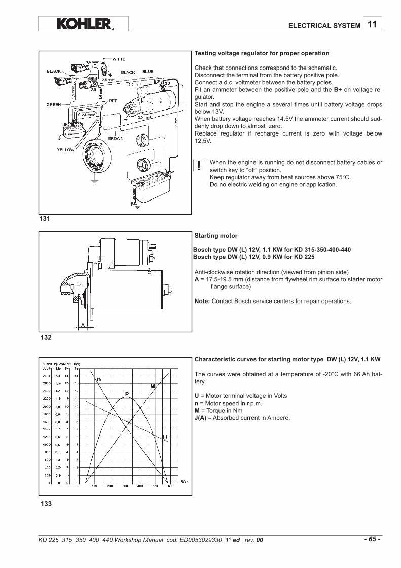
131
132
133
11
- 65 -
ELECTRICAL SYSTEM
Testing voltage regulator for proper operation
Checkthatconnectionscorrespondtotheschematic.Disconnecttheterminalfromthebatterypositivepole.Connectad.c.voltmeterbetweenthebatterypoles.FitanammeterbetweenthepositivepoleandtheB+onvoltagere-gulator.Startandstoptheengineaseveral timesuntilbatteryvoltagedropsbelow13V.Whenbatteryvoltagereaches14.5Vtheammetercurrentshouldsud-denlydropdowntoalmostzero.Replace regulator if recharge current is zero with voltage below12,5V.
Whentheengineisrunningdonotdisconnectbatterycablesorswitchkeyto"off"position.Keepregulatorawayfromheatsourcesabove75°C.Donoelectricweldingonengineorapplication.
Starting motor
Anti-clockwiserotationdirection(viewedfrompinionside)A =17.5-19.5mm(distancefromflywheelrimsurfacetostartermotor
flangesurface)
Note:ContactBoschservicecentersforrepairoperations.
Characteristic curves for starting motor type DW (L) 12V, 1.1 KW
Thecurveswereobtainedatatemperatureof-20°Cwith66Ahbat-tery.
U=MotorterminalvoltageinVoltsn =Motorspeedinr.p.m.M=TorqueinNmJ(A) =AbsorbedcurrentinAmpere.
KD 225_315_350_400_440 Workshop Manual_cod. ED0053029330_1° ed_ rev.00
Bosch type DW (L) 12V, 1.1 KW for KD 315-350-400-440Bosch type DW (L) 12V, 0.9 KW for KD 225

136
134
135
11
- 66 -
ELECTRICAL SYSTEM
Characteristic curves of Bosch starter motor type DW (L) 12V, 0.9 kW
Thecurvesweremeasuredata temperatureof -20°Cwitha55Ahbattery.
U=VoltageonmotorterminalsinVolts.n =MotorspeedinrpmM=TorqueinNmI (A) =PowerdrawinAmperes.
Characteristic curves of Bosch starter motor type DW (L) 24V, 1.6 kW
Thecurvesweremeasuredata temperatureof -20°Cwitha36Ahbattery.
U=VoltageonmotorterminalsinVolts.n =MotorspeedinrpmM=TorqueinNmI (A) =PowerdrawinAmperes..
Ignition switch positions
A=AccessoryB =OffC=OnD=Start
KD 225_315_350_400_440 Workshop Manual_cod. ED0053029330_1° ed_ rev.00

137
138 139
140 141
142
11
- 67 -
ELECTRICAL SYSTEM
Idling speed setting in no-load conditions (standard)
Afterfillingwithoilandfuel,starttheengineandletitwarmupfor10minutes.Adjustidlingspeedto1000-1250rpmbyturningsetscrew1;thentightenlocknut.Washer2assuressealingandpreventspossibleoilleaks.
Idle speed adjustment, for small car versions
Theidlespeedadjustingspring(C)forsmallcarsmustbehookedinthespeedgovernorleverhole D(fig.140).Completelyunscrewthestdidlespeedadjustingscrew1(fig.137).LoosennutBbyonehalfofaturn.Turnthescrew AanticlockwiseuntilleverGtouchescover.Starttheengine:turningclockwisescrewA ,setidlespeedat1050rpm;tightenthelocknutB tightenthescrew1(fig.137)untiltouchingleverH (fig.141);whenthescrewtouchesthelever,thespeedincreases;atthispointunloosescrew1/4ofaturnandlockthelocknutofscrew1.
Thecontrolscoverscrewsmustbetightenedto10Nm.
Note:Bythiswayidlespeedonhotenginecoulddiminishof80rpmmax.
Full speed setting in no-load conditions (standard)
Aftersettingidlespeedturnscrew2andsetfullspeedinno-loadcon-ditionsat3800rpm;thentightenlocknut.Washer 1assuressealingandpreventspossibleoilleaks.
KD 225_315_350_400_440 Workshop Manual_cod. ED0053029330_1° ed_ rev.00
ADJUSTMENTS - KD 315-350

145
146
143
144
12
- 68 -
SETTINGS / ADJUSTMENTS
No-load idling adjustment (standard)
Afterhavingfilled theenginewithoiland fuel,start itandallow it towarmupfor10minutes.Usingadjusterscrew1,regulatetheidlingrateat1000-1250rpm.Tightenthechecknut.
No-load top rate adjustment (standard)
Afterhavingadjustedtheidlingrate,usescrew2 andregulatethetoprateat3800rpm(forenginessetat3600rpmonload).Tightenthechecknut.
Injection pump flow rate adjustment
Thisregulationmustbecarriedoutbymeansofawaterbrake,other-wisetheadjustmentwillbeapproximate.proceedinthefollowingway.Loosenflowratelimiter Cby5turns.Acceleratetheenginetono-loadtoprate,i.e.to3800rpm.Re-tightenlimiterC untiltheenginetendstodecelerate.LoosenlimiterCbyoneandahalfturns.Tightenthechecknut.
Note:TightenCiftheengineproducesanexcessiveamountofexhaustinthemaximumloadcondition;loosen Cifnosmokeisexhaustedandiftheengineisunabletodevelopitsmaximumpower.
Injection pump delivery limiting and torque adapter (standard)
DeliverylimitingdeviceChasthefunctionoflimitingtheinjectionpumpmax.delivery.Thesamedevicealsoactsas torqueadapter. Thespeedgovernorspringactsonlever L withstandingtheresistanceopposedbyspringMinsidethecylinder.ThestrokeHallowedbythetorquedevicetoleverLis0.20/0.25mm.Asaresultofthispumpdeliveryincreasesandtorquereacesitspeakvalue.
Note:Ingeneratorsetsandpowerwelders,thetorquesettingdeviceactsasadeliverylimiteronly.
KD 225_315_350_400_440 Workshop Manual_cod. ED0053029330_1° ed_ rev.00
for KD 225-315-350-400-440
ADJUSTMENTS - KD 225-400-440

148
12
h.Wk/g
0063 05,3 892 782
0003 0,3 753 082
0063 0,5 242 572
0003 5,4 382 562
0063 5,5 891 572
0003 9,4 532 062
0063 3,7 151 572
0003 3,6 481 062
0063 0,8 731 572
0003 2,7 061 062
225
315
350
400
440
- 69 -
SETTINGS / ADJUSTMENT
Injection pump delivery setting
1)Bringenginetoidlingspeed2)UnscrewdeliverylimitingdeviceC (seefig.145)3)Bringtheenginetothepowerandrpmrequiredbythemanufactu-
rerofthedevice.4) Check that fuel consumption falls within the table specifications
(seebelow).Ifconsumptionisnotasindicatedchangebalanceconditionsatthetorquedynamometerbyvaryingthe loadandadjustingthegover-nor.Understableengineconditionscheckconsumptionagain.
5)TightenlimitingdeviceCuntiltheenginerpmdecreases.Lockthelimitingdevicebymeansoflocknut.
6) Release brake completely and check at what speed the enginebecomesstableSpeedgovernorshouldcomplywiththerequirementsoftheclassindicatedbythemanufacturerofthedevice.
7)Stoptheengine.8)Checkvalveclearancewhenenginehascooleddown.
Required settings (the most common ones)
Engine R.P.M. Power kW
Specific fuel consumption
Time (sec)pour 100 cc
KD 225_315_350_400_440 Workshop Manual_cod. ED0053029330_1° ed_ rev.00

13
5
5
5
- 70 -
STORAGE
Internal engine protection:
-Starttheengineandallowittoheatup.-Removethedrainplugandlettheoilflowoutcompletely.-Replacetheoilfilterwithanewone.- Clean the oil drain plug and after inserting a new gasket,tightenit.- Fill upwith oil to the upper level of the dipstick, usingAGIPRUSTIA C30 (for countries in which this product is notavailablefindanequivalentproductonthemarket).-Starttheengineforabout10minutes,checkforoilleaks,andthenstoptheengine.
Injection systems protection:
-Emptythefueltank.-Replacethefuelfilterwithanewone.-Fillupwithfuelcontaining10%AGIPRUSTIANT.-Afterbleedingair,starttheengine,makesuretherearenofuelleaksandthenstoptheengine.
External engine protection:
- Carefully clean the cylinder cooling system fins and theflywheelfins.-Protect theexternal non-painted surfaceswithAGIPRUSTIA68/F.-Sealtheintakeandexhaustsystemswithadhesivetape.-Covertheenginewithanylonorplasticsheet.-Storeinadryplace,preferablynotdirectlyonthegroundandawayfromhighvoltageelectricitylines.
STORAGE
When the engines are not used for more than 3 months, they must be protected by the measures described below:
KD 225_315_350_400_440 Workshop Manual_cod. ED0053029330_1° ed_ rev.00

14
174
175
- 71 -
STORAGE
-Removeallprotectionsandcoverings.
- Remove the protective oil from the outside of the engine usingsuitableproducts(solventordegreaser).
-Removetheinjectorand,usingaflask,pourengineoilonthepistoncrown(nomorethan2cc).
-Removerockerarmcoverandsprayengineoilonthevalves,thenturnthecrankshaftmanuallyafewrevolutions.
-Starttheengineandallowittoheatupforabout10minutes.
-Removethedrainplugandlettheprotectiveoilflowoutcompletely.
-Replacethedrainplug.
- Fill up with engine oil as far as the upper level of the dipstickusing the oil recommended by the manufacturer for normal engineoperation.
PROCEDURES TO BE CARRIED OUT BEFORE START THE ENGINE
KD 225_315_350_400_440 Workshop Manual_cod. ED0053029330_1° ed_ rev.00

15
fig.18-p.25fig.51-p.36
fig.13-p.23fig.13-p.23fig.19-p.25fig.12-p.23
---
fig.3-p.20fig.90-p.49
fig.103-104-p53-
fig.9-10-p.22fig.100-p.52
-fig.102-p.53fig.84-p.48fig.81-p.45
-
fig.105-p.54fig.14-p.24
--
fig.21-p.26fig.21-p.26
-fig.20-p.25
Loctite648BVLoctite“Form-a-gasketN.6”
Loctite222Loctite222Loctite222Loctite222Loctite222Loctite270Loctite270Loctite270Loctite270Loctite270Loctite270Loctite270Loctite270Loctite270Loctite480Loctite5205Loctite5205Loctite5205
MOLYSLIPASCOMPOUND40
1030--720101010--251099251540101023-
-15-20-10-
150
6x18x17x18x16x0,58x1,256x16x16x1
10x1,58x1,258x1,256x16x16x1
8x1,258x1,2514x1,56x16x1
8x1,2510x1,5
14x1,58x1,258x1,2514x1,5
-6x1
8x1,2514x1,5sinistra
10-23-720101010--2510912251540151023-
-15-20-10-
150
1030-35106101010402525109925154010102315
40151520-1025150
315-350225 400-440
- 72 -
POSITION
USE OF SEALANT
LockingofadjustmentleverboxAirvalvecaseM6fixingscrewforfuelfilterM8fixingscrewformufflerbracketM8fixingscrewsforfuelsupplypumpM16fixingscrewforoilintakefilterandcoverM6finxingscrewsforairshroudM6studboltfordryairfiltercoverM6fixingscrewsforsideoilrefillingunionM6screwforinjectiontappetguideM8STEIscrewforclosingoilintakeholecoverM8STEIscrewforclosingcrankcaselubricationholeM8fixingscrewsforairfiltersupportandintakemanifoldRockerarmfulcrumscrewsStatorscrewsM8studboltsfortankPlastoferriteonflywheelBasecouplingsurface-coverCouplingsurfaceforenhancedengineoilsumpCouplingsurfaceforenhancedoilsumphalf-shellsHydraulictappetcontact-cam
TYPE OF SEALANT
MAIN TORQUE SPECIFICATIONS
Re-coilstartingConnectingrod,aluminium
Connectingrod,steelRockerarmadjustingscrewlocknutRockerarmadjustingscrewpinShroudRockerarmcoverControlarmcoverEnhancedengineoilsumpExhaustmanifoldAircleanersupportOilfilterheadInjectiontappetguidescrewInjectorfixingontotheheadMuffleronmanifoldFuelpumpInjectionpumpunionInjectionpumpfasteningscrewsOilpumpsupportGearcover,timingsideCalibrated fitting for hydraulic tappetlubricationInjectionpumpdeliveryunionFueltankbottomlowerfixingEnhancedsumphalf-shellsFueltanktopfixingOildrainplugCylinderhead(*)FlywheelpulleyfixingscrewsFlywheel
POSITIONDiam. and pitch
( mm )Reference ( fig. N° and page)
Torque ( Nm ) Torque ( Nm ) Torque ( Nm )
TORQUE SPECIFICATIONS
KD 225_315_350_400_440 Workshop Manual_cod. ED0053029330_1° ed_ rev.00

15
R>400N/mm2 R>500N/mm2 R>600N/mm2 R>800N/mm2 R>1000N/mm2 R>1200N/mm2
Nm Nm Nm Nm Nm Nm Nm NmM3 0,5 0,7 0,6 0,9 1 1,4 1,9 2,3M4 1,1 1,5 1,4 1,8 2,2 2,9 4,1 4,9M5 2,3 3 2,8 3,8 4,5 6 8,5 10M6 3,8 5 4,7 6,3 7,5 10 14 17M8 9,4 13 12 16 19 25 35 41M10 18 25 23 31 37 49 69 83M12 32 43 40 54 65 86 120 145M14 51 68 63 84 101 135 190 230M16 79 105 98 131 158 210 295 355M18 109 145 135 181 218 290 405 485M20 154 205 193 256 308 410 580 690M22 206 275 260 344 413 550 780 930M24 266 355 333 444 533 710 1000 1200M27 394 525 500 656 788 1050 1500 1800M30 544 725 680 906 1088 1450 2000 2400
4.6 4.8 5.6 5.8 6.8 8.8 10.9 12.9
R>400N/mm2 R>500N/mm2 R>600N/mm2 R>800N/mm2 R>1000N/mm2 R>1200N/mm2
Nm Nm Nm Nm Nm Nm Nm NmM8x1 10 14 13 17 20 27 38 45M10x1 21 28 26 35 42 56 79 95M10x1,25 20 26 24 33 39 52 73 88M12x1,25 36 48 45 59 71 95 135 160M12x1,5 38 45 42 56 68 90 125 150M14x1,5 56 75 70 94 113 150 210 250M16x1,5 84 113 105 141 169 225 315 380M18x1,5 122 163 153 203 244 325 460 550M18x2 117 157 147 196 235 313 440 530M20x1,5 173 230 213 288 345 460 640 770M20x2 164 218 204 273 327 436 615 740M22x1,5 229 305 287 381 458 610 860 1050M24x2 293 390 367 488 585 780 1100 1300M27x2 431 575 533 719 863 1150 1600 1950M30x2 600 800 750 1000 1200 1600 2250 2700
4.6 4.8 5.6 5.8 6.8 8.8 10.9 12.9
Table of tightening torques for standard screws (fine thread)
- 73 -
Table of tightening torques for standard screws (coarse thread)
Resistanceclass(R)
Quality/Dimensions
Diameter
Quality/Dimensions
Resistanceclass(R)
Diameter
TORQUE SPECIFICATIONS
KD 225_315_350_400_440 Workshop Manual_cod. ED0053029330_1° ed_ rev.00

FORMNO. ED0053029330ISSUED 25/06/2012
REVISED 00 DATE 25/06/2012ENGINEDIVISION,KOHLERCO.,KOHLER,WISCONSIN53044
FORSALESANDSERVICEINFORMATIONINU.S.ANDCANADA,CALL 1-800-544-2444KohlerEngines.com
Translated from the original manual in Italian language.
Data reported in this issue can be modified at any time by KOHLER.