KCC MSM8C104ex V103 - RTSoft file2.1 MSM8C104EX Ordering Information.....8 2.2 Understanding...
40
If it's embedded, it's Kontron. Wa MSM8C104EX Document Revision 103
Transcript of KCC MSM8C104ex V103 - RTSoft file2.1 MSM8C104EX Ordering Information.....8 2.2 Understanding...
If it's embedded, it's Kontron.
Wa
MSM8C104EX Document Revision 103

www.kontron.com
» Table of Contents «
1 User Information............................................................................ 4
1.1 About This Document ...............................................................................................................4
1.2 Copyright Notice .....................................................................................................................4
1.3 Trademarks ............................................................................................................................4
1.4 Standards..............................................................................................................................4
1.5 Warranty ...............................................................................................................................4
1.6 Technical Support ...................................................................................................................5
1.7 Environmental Protection Statement ...........................................................................................5
1.8 RoHS Commitment ..................................................................................................................5
1.8.1 RoHS Compatible Product Design...............................................................................................6
1.8.2 RoHS Compliant Production Process ...........................................................................................6
1.8.3 WEEE Application ...................................................................................................................6
1.9 Swiss Quality ..........................................................................................................................6
1.10 The Swiss Association for Quality and Management Systems..............................................................7
2 Introduction ................................................................................. 8
2.1 MSM8C104EX Ordering Information.............................................................................................8
2.2 Understanding MSM8C104EX Functionality ...................................................................................8
2.3 MICROSPACE® Documentation ....................................................................................................8
2.4 MSM8C104EX Benefits ..............................................................................................................8
3 Specifications................................................................................ 9
3.1 Functional Specifications ..........................................................................................................9
3.2 Dimensions............................................................................................................................9
3.3 Electrical Specifications............................................................................................................9
3.4 Environmental Specifications.....................................................................................................9
3.5 8-Channel UART .................................................................................................................... 10
3.5.1 UART 958 Controller Specifications .......................................................................................... 10
4 Electrical Interfaces .......................................................................11
4.1 RS232 Electrical Interface ....................................................................................................... 11
4.2 RS422/485 Electrical Interface................................................................................................. 11

www.kontron.com
4.2.1 Full Duplex Mode ................................................................................................................. 11
4.2.2 Half Duplex Mode................................................................................................................. 11
4.2.3 Multi-drop Mode .................................................................................................................. 11
4.3 Line Bias/Termination............................................................................................................ 11
5 MSM8C104EX Connectors & Jumpers..................................................12
5.1 Connector & Jumper Locations................................................................................................. 12
5.2 Connector Pinouts ................................................................................................................. 13
5.2.1 X1 COM1-4 Connector............................................................................................................ 13
5.2.2 X2 COM5-8 Connector............................................................................................................ 14
5.2.3 X3 PCI Connector ................................................................................................................. 14
5.2.4 X5 PCI/104-Express Bus (Bottom View Signal Assignment)............................................................ 15
5.2.5 Connector Diagrams ............................................................................................................. 17
5.3 Jumpers.............................................................................................................................. 18
5.3.1 J3 Termination RS422/485..................................................................................................... 18
5.3.2 J7 Selection of RS232 or Differential (RS422/485) Interface ......................................................... 18
6 LEDs ...........................................................................................19
7 Driver Installation & Settings ...........................................................20
7.1 Driver Installation on Windows XP............................................................................................. 20
7.2 Port Settings ........................................................................................................................ 29
7.2.1 COM Port Number ................................................................................................................. 29
7.2.2 FIFOs................................................................................................................................. 30
8 Assembly Views .............................................................................31
8.1 Top Side .............................................................................................................................. 31
8.2 Bottom Side......................................................................................................................... 32
9 Appendix A: Architecture Information................................................33
9.1 Buses ................................................................................................................................. 33
9.1.1 ISA, Standard PS/2 – Connectors............................................................................................. 33
9.1.2 PCI/104 ............................................................................................................................. 33
9.2 General PC Architecture .......................................................................................................... 33
9.3 Ports .................................................................................................................................. 34
9.3.1 RS232 Serial ....................................................................................................................... 34
9.3.2 Serial ATA........................................................................................................................... 34
9.3.3 USB .................................................................................................................................. 34
www.kontron.com
9.4 Programming ....................................................................................................................... 34
10 Appendix B: Document Revision History .............................................35
11 Index..........................................................................................36
MSM8C104EX / User Information
www.kontron.com 4
1 User Information
1.1 About This Document
This document provides information about products from Kontron AG and/or its subsidiaries. No warranty of
suitability, purpose, or fitness is implied. While every attempt has been made to ensure that the information in this
document is accurate, the information contained within is supplied "as-is" and is subject to change without notice.
For the circuits, descriptions and tables indicated, Kontron assumes no responsibility as far as patents or other rights
of third parties are concerned.
1.2 Copyright Notice
Copyright© 2003-2011 Kontron AG
All rights reserved. No part of this document may be reproduced, transmitted, transcribed, stored in a retrieval
system, or translated into any language or computer language, in any form or by any means (electronic, mechanical,
photocopying, recording, or otherwise), without the express written permission of Kontron AG.
The software described herein, together with this document, are furnished under a license agreement and may be
used or copied only in accordance with the terms of that agreement.
1.3 Trademarks
MICROSPACE®, smartModule®, smartCore®Express and DIGITAL-LOGIC® are trademarks or registered trademarks of
Kontron Compact Computers AG. Kontron is a trademark or registered trademark of Kontron AG.
The following lists some of the trademarks of components used in this product.
» IBM, XT, AT, PS/2 and Personal System/2 are trademarks of International Business Machines Corp.
» Microsoft is a registered trademark of Microsoft Corp.
» Intel is a registered trademark of Intel Corp.
All other products and trademarks mentioned in this manual are trademarks of their respective owners.
1.4 Standards
Kontron AG is certified to ISO 9000 standards.
1.5 Warranty
This Kontron AG product is warranted against defects in material and workmanship for the warranty period from the
date of shipment. During the warranty period, Kontron AG will, at its discretion, decide to repair or replace defective
products.
Within the warranty period, the repair of products is free of charge as long as warranty conditions are observed.
The warranty does not apply to defects resulting from improper or inadequate maintenance or handling by the buyer,
unauthorized modification or misuse, operation outside of the product’s environmental specifications or improper
installation or maintenance.
Kontron AG will not be responsible for any defects or damages to other products not supplied by Kontron AG that are
caused by a faulty Kontron AG product.
Empty batteries (external and onboard), as well as all other battery failures, are not covered by this manufacturer’s
limited warranty.

MSM8C104EX / User Information
www.kontron.com 5
1.6 Technical Support
Technicians and engineers from Kontron AG and/or its subsidiaries are available for technical support. We are
committed to making our products easy to use and will help you use our products in your systems.
Please consult our Web site at http://www.kcc-ag.ch/index.php?id=products-download for the latest product
documentation, BIOS, drivers, tools and software information.
For technical support consult http://support.kcc-ag.ch/ .
1.7 Environmental Protection Statement
This product has been manufactured to satisfy environmental protection requirements wherever possible. Many of the
components used (structural parts, printed circuit boards, connectors, batteries, etc.) are capable of being recycled.
Final disposal of this product after its service life must be accomplished in accordance with applicable country, state,
or local laws or regulations. All components within this product fulfill the requirements of the RoHS (Restriction of
Hazardous Substances Directive). The product is soldered with a lead free process.
1.8 RoHS Commitment
Kontron Compact Computers AG (Switzerland) is committed to develop and produce environmentally friendly products
according to the Restriction of Hazardous Substances (RoHS) Directive (2002/95/EC) and the Waste Electrical and
Electronic Equipment (WEEE) Directive (2002/96/EC) established by the European Union. The RoHS directive was
adopted in February 2003 by the European Union and came into effect on July 1, 2006. It is not a law but a directive,
which restricts the use of six hazardous materials in the manufacturing of various types of electronic and electrical
equipment. It is closely linked with the Waste Electrical and Electronic Equipment Directive (WEEE) 2002/96/EC,
which has set targets for collection, recycling and recovery of electrical goods and is part of a legislative initiative to
solve the problem of huge amounts of toxic e-waste.
Each European Union member state is adopting its own enforcement and implementation policies using the directive
as a guide. Therefore, there could be as many different versions of the law as there are states in the EU. Additionally,
non-EU countries like China, Japan, or states in the U.S. such as California may have their own regulations for green
products, which are similar, but not identical, to the RoHS directive.
RoHS is often referred to as the "lead-free" directive but it restricts the use of the following substances:
» Lead
» Mercury
» Cadmium
» Chromium VI
» PBB and PBDE
The maximum allowable concentration of any of the above mentioned substances is 0.1% (except for Cadmium, which
is limited to 0.01%) by weight of homogeneous material. This means that the limits do not apply to the weight of the
finished product, or even to a component but to any single substance that could (theoretically) be separated
mechanically.

MSM8C104EX / User Information
www.kontron.com 6
1.8.1 RoHS Compatible Product Design
All standard products from Kontron Compact Computers (KCC) comply with RoHS legislation.
Since July 1, 2006, there has been a strict adherence to the use of RoHS compliant electronic and mechanical
components during the design-in phase of all KCC standard products.
1.8.2 RoHS Compliant Production Process
KCC selects external suppliers that are capable of producing RoHS compliant devices verified by:
» A confirmation from the supplier indicating that their production processes and resulting devices are RoHS compliant.
» If there is any doubt of the RoHS compliancy, the concentration of the previously mentioned substances in a produced device will be measured. These measurements are carried out by an accredited laboratory.
1.8.3 WEEE Application
The WEEE directive is closely related to the RoHS directive and applies to the following devices:
» Large and small household appliances
» IT equipment
» Telecommunications equipment (although infrastructure equipment is exempt in some countries)
» Consumer equipment
» Lighting equipment – including light bulbs
» Electronic and electrical tools
» Toys, leisure and sports equipment
» Automatic dispensers
It does not apply to fixed industrial plants and tools. The compliance is the responsibility of the company that brings
the product to market, as defined in the directive. Components and sub-assemblies are not subject to product
compliance. In other words, since Kontron Compact Computers AG does not deliver ready-made products to end users
the WEEE directive is not applicable for KCC. Users are nevertheless encouraged to properly recycle all electronic
products that have reached the end of their life cycle.
1.9 Swiss Quality
» 100% Made in Switzerland
» This product was not manufactured by employees earning piecework wages
» This product was manufactured in humane work conditions
» All employees who worked on this product are paid customary Swiss market wages and are insured
» ISO 9000:2001 (quality management system)
MSM8C104EX / User Information
www.kontron.com 7
1.10 The Swiss Association for Quality and Management Systems
The Swiss Association for Quality and Management Systems (SQS) provides certification and assessment services for
all types of industries and services. SQS certificates are accepted worldwide thanks to accreditation by the Swiss
Accreditation Service (SAS), active membership in the International Certification Network, IQNet, and co-operation
contracts/agreements with accredited partners.
www.sqs.ch
The SQS Certificate ISO 9001:2000 has been issued to Kontron Compact Computers AG in the field of development,
manufacturing and sales of embedded computer boards, embedded computer modules and computer systems. The
certification is valid for three years at which time an audit is performed for recertification.
MSM8C104EX / Introduction
www.kontron.com 8
2 Introduction
2.1 MSM8C104EX Ordering Information
Part / Option Part Number Description
MSM8C104ex, 8 channel 801725 PCIe + PCI
MSM8C104ex, 16 channel 801726 PCIe + PCI
MSM8C104 cable kit 802036 4x DSUB9 (2x kit)
2.2 Understanding MSM8C104EX Functionality
The MSM8C104ex MICROSPACE® PCI/104-Express expansion card has a choice of either 8 or 16 serial interfaces
available. Each channel can be singly selected as RS232C (+/-9V) or as RS422/485 each with 4 paired wires (TxD, RxD,
CTS, RTS).
» 8 ch. serial high speed interface
» 8x RS422/485 up to 2 Mbit/s, 256 devices or 3x RS232C up to 115k baud, 128 Byte TX/RX-FIFO
» Software and FPGA configurable flow control
» PCI104: pass-through
» The MSM8C104express is PCI/104-Express, version 1.0, compliant.
2.3 MICROSPACE® Documentation
This manual is written for the original equipment manufacturer (OEM) who plans to build computer systems based on
the single board MICROSPACE-PC. It is for integrators and programmers of systems based on the MICROSPACE-
Computer family. This manual provides instructions for installing and configuring the board and describes the system
and setup requirements. This document contains information on hardware requirements, interconnections, and
details of how to program the system. Please check the Product CD for further information and manuals.
2.4 MSM8C104EX Benefits
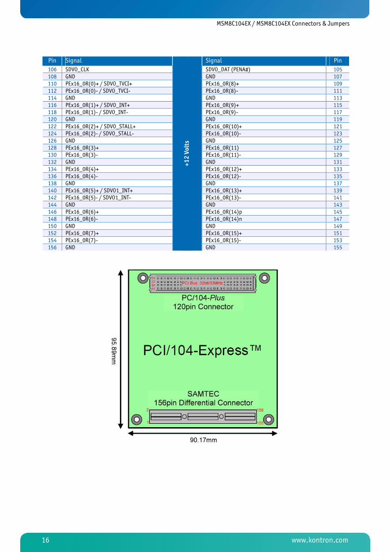
MICROSPACE PCI/104-Express embedded computer boards comply with the PC/104 Consortium form factor 3.55 ×
3.775 inches (90.17 × 95.89 mm) and are available in "stack through" versions.

MSM8C104EX / Specifications
www.kontron.com 9
3 Specifications
Note: All information is subject to change without notice.
3.1 Functional Specifications
Bus
» Standard: PC/104express
» Size: 32 bit PCIe
3.2 Dimensions
» Length: 90 mm
» Width: 96 mm
» Height: 15 mm
3.3 Electrical Specifications
Power Supply
» Working: 5 Volt / 1 W
3.4 Environmental Specifications
Temperature
» Operating, standard version: -25°C to +85°C
» Operating, industrial version: -40°C to +85°C
» Non-operating (storage): -55°C to +85°C
Vibration
» 5 to 2000 Hz
Humidity
» 5% to 90% (non-condensing)
Shock
» 10g

MSM8C104EX / Specifications
www.kontron.com 10
3.5 8-Channel UART
COM Interface Specification Remarks
Controller OXPCIE958
Enhanced BIOS no
UART-FIFO 128 Byte each channel
RS232C MAX211E up to 115 kBaud +/-8V converter
RS422/485 LTC2855 up to 15 MBaud 1/8 power
Interface 8x header for D-sub9
3.5.1 UART 958 Controller Specifications
» High performance Oxford Semiconductor 950 controller
» Asynchronous baud rates up to 15Mbps
» 128 Byte deep TX/RX FIFOs
» 9, 8, 7, 6 & 5 bit data framing
» Flexible clock prescaler from 1 to 31,875
» Automated in-band, XON/XOFF flow control
» Automated hardware flow control
» Advanced FIFO fill management
» Programmable RS485 turn around delay
» 450 through 950 software compatibility
» Serial expansion to 16 channels via a second card
» MSI/MSI-X compatible
» DMA Bus mastering for all UARTs
» ASPM Link power management
» PCI Express base spec 1.1 compliant
» 1.8V core voltage
» Industrial temperature range for the controller
» Support for XP, Vista, CE, Linux
The device combines a fully integrated, single lane PCI express end point controller and SerDes with eight high
performance Oxford Semiconductor 950 UARTs, user defined GPIOs/PWMs and a dedicated port expansion interface. It
includes advanced system management features such as MSI/MSI-X interrupt handling and Bus master DMA to
maximize data throughput while substantially reducing CPU and system overheads. Each 950 UART has a full modem
interface and includes hardware-accelerated out of band and in-band flow control, readable FIFO levels and RS485
turn around delay for further performance optimization.
Refer also to the datasheet "OXPCIe958" from Oxford Semiconductor (PLX Technology).
MSM8C104EX / Electrical Interfaces
www.kontron.com 11
4 Electrical Interfaces For the 8-Channel UART with RS232 and RS422/485
4.1 RS232 Electrical Interface
This is the default setting for the selectable interface of the MSM8C104ex. To operate a port in RS232 mode, there are
no jumpers installed on the corresponding jumper block.
4.2 RS422/485 Electrical Interface
MSM8C104ex models offer three modes of RS422/485 communication, as outlined below.
4.2.1 Full Duplex Mode
TxD+/- is being driven to a known level at all times in this mode. This mode is typically used in point-to-point
situations much like RS232. It is the default setting for RS422/485 mode.
4.2.2 Half Duplex Mode
In this mode, when data is transmitted, the TxD+/- line driver is enabled and RxD+/- is disabled. This mode is typically
used in either point-to-point 2-wire connections or in multi-drop 2-wire Bus connections. This mode requires
software setup.
DTR is used to control the RS485 transmitter enable signal.
4.2.3 Multi-drop Mode
In this mode, the TxD+/- line driver is enabled only when data is transmitted and RxD+/- is enabled all the time. This
mode is typically used in multi-drop 4-wire connections. This mode requires software setup.
4.3 Line Bias/Termination
The RS422/485 transceivers can be configured to terminate and produce a line level mark condition on the receiver,
and/or terminate the transmitter. These options are enabled through on-board jumper selectable resistors. These
options are typically used in multi-drop 4-wire or half duplex 2-wire connections.
MSM8C104EX / MSM8C104EX Connectors & Jumpers
www.kontron.com 12
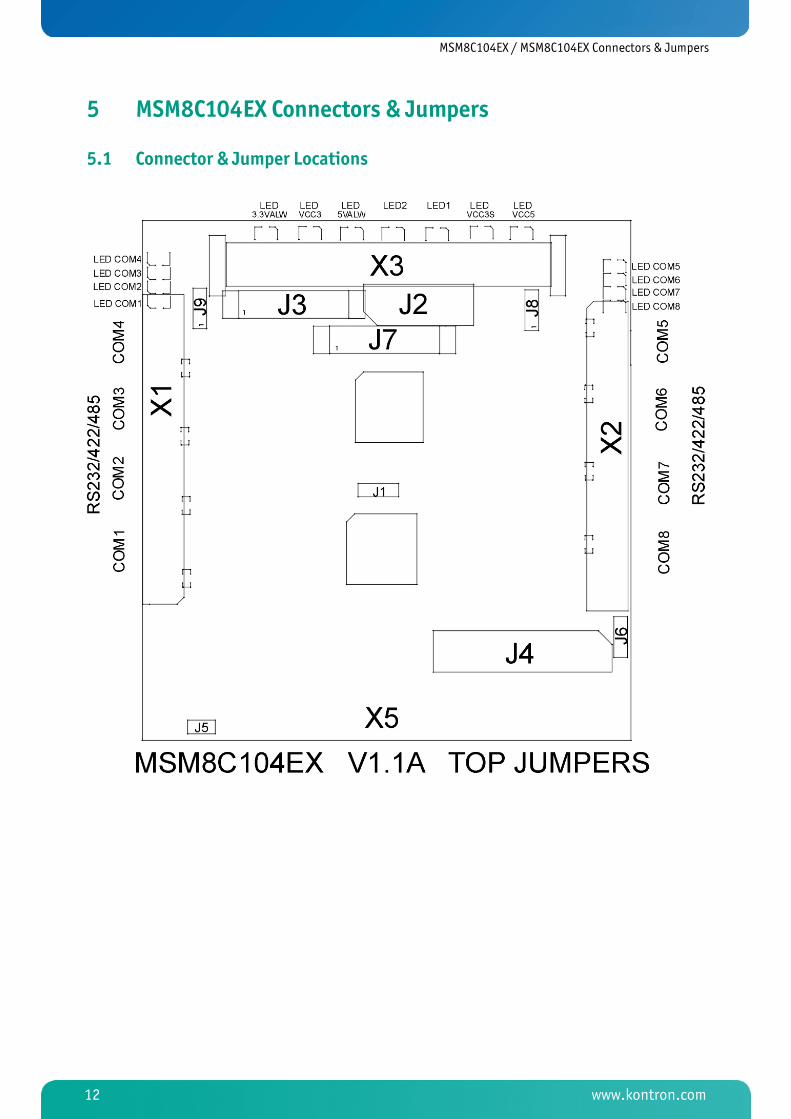
5 MSM8C104EX Connectors & Jumpers
5.1 Connector & Jumper Locations

MSM8C104EX / MSM8C104EX Connectors & Jumpers
www.kontron.com 13
5.2 Connector Pinouts
5.2.1 X1 COM1-4 Connector
Header Onboard RS232 Signal RS422/85 Signal D-Sub Connector
Pin 1 COM1 DCD RXD+ Pin 1 Pin 2 DSR CTS- Pin 6 Pin 3 RxD RXD- Pin 2 Pin 4 RTS RTS+ Pin 7 Pin 5 TxD TXD+ Pin 3 Pin 6 CTS CTS+ Pin 8 Pin 7 DTR TXD- Pin 4 Pin 8 RI RTS- Pin 9 Pin 9 GND GND Pin 5 Pin 10 open
Pin 11 COM2 DCD RXD+ Pin 1 Pin 12 DSR CTS- Pin 6 Pin 13 RxD RXD- Pin 2 Pin 14 RTS RTS+ Pin 7 Pin 15 TxD TXD+ Pin 3 Pin 16 CTS CTS+ Pin 8 Pin 17 DTR TXD- Pin 4 Pin 18 RI RTS- Pin 9 Pin 19 GND GND Pin 5 Pin 20 open
Pin 21 COM3 DCD RXD+ Pin 1 Pin 22 DSR CTS- Pin 6 Pin 23 RxD RXD- Pin 2 Pin 24 RTS RTS+ Pin 7 Pin 25 TxD TXD+ Pin 3 Pin 26 CTS CTS+ Pin 8 Pin 27 DTR TXD- Pin 4 Pin 28 RI RTS- Pin 9 Pin 29 GND GND Pin 5 Pin 30 open
Pin 31 COM4 DCD RXD+ Pin 1 Pin 32 DSR CTS- Pin 6 Pin 33 RxD RXD- Pin 2 Pin 34 RTS RTS+ Pin 7 Pin 35 TxD TXD+ Pin 3 Pin 36 CTS CTS+ Pin 8 Pin 37 DTR TXD- Pin 4 Pin 38 RI RTS- Pin 9 Pin 39 GND GND Pin 5 Pin 40 open

MSM8C104EX / MSM8C104EX Connectors & Jumpers
www.kontron.com 14
5.2.2 X2 COM5-8 Connector
Header Onboard RS232 Signal RS422/85 Signal D-Sub Connector
Pin 1 COM5 DCD RXD+ Pin 1 Pin 2 DSR CTS- Pin 6 Pin 3 RxD RXD- Pin 2 Pin 4 RTS RTS+ Pin 7 Pin 5 TxD TXD+ Pin 3 Pin 6 CTS CTS+ Pin 8 Pin 7 DTR TXD- Pin 4 Pin 8 RI RTS- Pin 9 Pin 9 GND GND Pin 5 Pin 10 open
Pin 11 COM6 DCD RXD+ Pin 1 Pin 12 DSR CTS- Pin 6 Pin 13 RxD RXD- Pin 2 Pin 14 RTS RTS+ Pin 7 Pin 15 TxD TXD+ Pin 3 Pin 16 CTS CTS+ Pin 8 Pin 17 DTR TXD- Pin 4 Pin 18 RI RTS- Pin 9 Pin 19 GND GND Pin 5 Pin 20 open
Pin 21 COM7 DCD RXD+ Pin 1 Pin 22 DSR CTS- Pin 6 Pin 23 RxD RXD- Pin 2 Pin 24 RTS RTS+ Pin 7 Pin 25 TxD TXD+ Pin 3 Pin 26 CTS CTS+ Pin 8 Pin 27 DTR TXD- Pin 4 Pin 28 RI RTS- Pin 9 Pin 29 GND GND Pin 5 Pin 30 open
Pin 31 COM7 DCD RXD+ Pin 1 Pin 32 DSR CTS- Pin 6 Pin 33 RxD RXD- Pin 2 Pin 34 RTS RTS+ Pin 7 Pin 35 TxD TXD+ Pin 3 Pin 36 CTS CTS+ Pin 8 Pin 37 DTR TXD- Pin 4 Pin 38 RI RTS- Pin 9 Pin 39 GND GND Pin 5 Pin 40 open
5.2.3 X3 PCI Connector
This is a stack-through PCI connector.
MSM8C104EX / MSM8C104EX Connectors & Jumpers
www.kontron.com 15
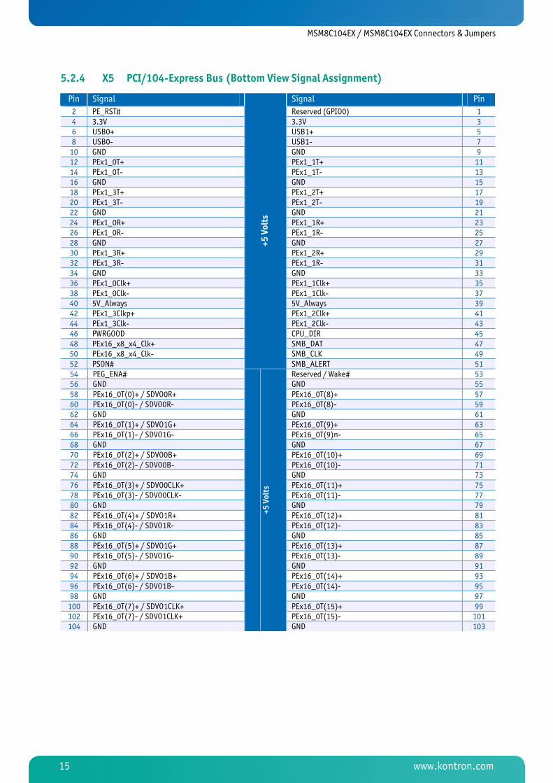
5.2.4 X5 PCI/104-Express Bus (Bottom View Signal Assignment)
Pin Signal Signal Pin
2 PE_RST# Reserved (GPIO0) 1 4 3.3V 3.3V 3 6 USB0+ USB1+ 5 8 USB0- USB1- 7 10 GND GND 9 12 PEx1_0T+ PEx1_1T+ 11 14 PEx1_0T- PEx1_1T- 13 16 GND GND 15 18 PEx1_3T+ PEx1_2T+ 17 20 PEx1_3T- PEx1_2T- 19 22 GND GND 21 24 PEx1_0R+ PEx1_1R+ 23 26 PEx1_0R- PEx1_1R- 25 28 GND GND 27 30 PEx1_3R+ PEx1_2R+ 29 32 PEx1_3R- PEx1_1R- 31 34 GND GND 33 36 PEx1_0Clk+ PEx1_1Clk+ 35 38 PEx1_0Clk- PEx1_1Clk- 37 40 5V_Always 5V_Always 39 42 PEx1_3Clkp+ PEx1_2Clk+ 41 44 PEx1_3Clk- PEx1_2Clk- 43 46 PWRGOOD CPU_DIR 45 48 PEx16_x8_x4_Clk+ SMB_DAT 47 50 PEx16_x8_x4_Clk- SMB_CLK 49 52 PSON#
+5 Volts
SMB_ALERT 51 54 PEG_ENA# Reserved / Wake# 53 56 GND GND 55 58 PEx16_0T(0)+ / SDVO0R+ PEx16_0T(8)+ 57 60 PEx16_0T(0)- / SDVO0R- PEx16_0T(8)- 59 62 GND GND 61 64 PEx16_0T(1)+ / SDVO1G+ PEx16_0T(9)+ 63 66 PEx16_0T(1)- / SDVO1G- PEx16_0T(9)n- 65 68 GND GND 67 70 PEx16_0T(2)+ / SDVO0B+ PEx16_0T(10)+ 69 72 PEx16_0T(2)- / SDVO0B- PEx16_0T(10)- 71 74 GND GND 73 76 PEx16_0T(3)+ / SDVO0CLK+ PEx16_0T(11)+ 75 78 PEx16_0T(3)- / SDVO0CLK- PEx16_0T(11)- 77 80 GND GND 79 82 PEx16_0T(4)+ / SDVO1R+ PEx16_0T(12)+ 81 84 PEx16_0T(4)- / SDVO1R- PEx16_0T(12)- 83 86 GND GND 85 88 PEx16_0T(5)+ / SDVO1G+ PEx16_0T(13)+ 87 90 PEx16_0T(5)- / SDVO1G- PEx16_0T(13)- 89 92 GND GND 91 94 PEx16_0T(6)+ / SDVO1B+ PEx16_0T(14)+ 93 96 PEx16_0T(6)- / SDVO1B- PEx16_0T(14)- 95 98 GND GND 97 100 PEx16_0T(7)+ / SDVO1CLK+ PEx16_0T(15)+ 99 102 PEx16_0T(7)- / SDVO1CLK+ PEx16_0T(15)- 101 104 GND
+5 Volts
GND 103
MSM8C104EX / MSM8C104EX Connectors & Jumpers
www.kontron.com 16
Pin Signal Signal Pin
106 SDVO_CLK SDVO_DAT (PENA#) 105 108 GND GND 107 110 PEx16_0R(0)+ / SDVO_TVCI+ PEx16_0R(8)+ 109 112 PEx16_0R(0)- / SDVO_TVCI- PEx16_0R(8)- 111 114 GND GND 113 116 PEx16_0R(1)+ / SDVO_INT+ PEx16_0R(9)+ 115 118 PEx16_0R(1)- / SDVO_INT- PEx16_0R(9)- 117 120 GND GND 119 122 PEx16_0R(2)+ / SDVO_STALL+ PEx16_0R(10)+ 121 124 PEx16_0R(2)- / SDVO_STALL- PEx16_0R(10)- 123 126 GND GND 125 128 PEx16_0R(3)+ PEx16_0R(11) 127 130 PEx16_0R(3)- PEx16_0R(11)- 129 132 GND GND 131 134 PEx16_0R(4)+ PEx16_0R(12)+ 133 136 PEx16_0R(4)- PEx16_0R(12)- 135 138 GND GND 137 140 PEx16_0R(5)+ / SDVO1_INT+ PEx16_0R(13)+ 139 142 PEx16_0R(5)- / SDVO1_INT- PEx16_0R(13)- 141 144 GND GND 143 146 PEx16_0R(6)+ PEx16_0R(14)p 145 148 PEx16_0R(6)- PEx16_0R(14)n 147 150 GND GND 149 152 PEx16_0R(7)+ PEx16_0R(15)+ 151 154 PEx16_0R(7)- PEx16_0R(15)- 153 156 GND
+12 Volts
GND 155
MSM8C104EX / MSM8C104EX Connectors & Jumpers
www.kontron.com 17
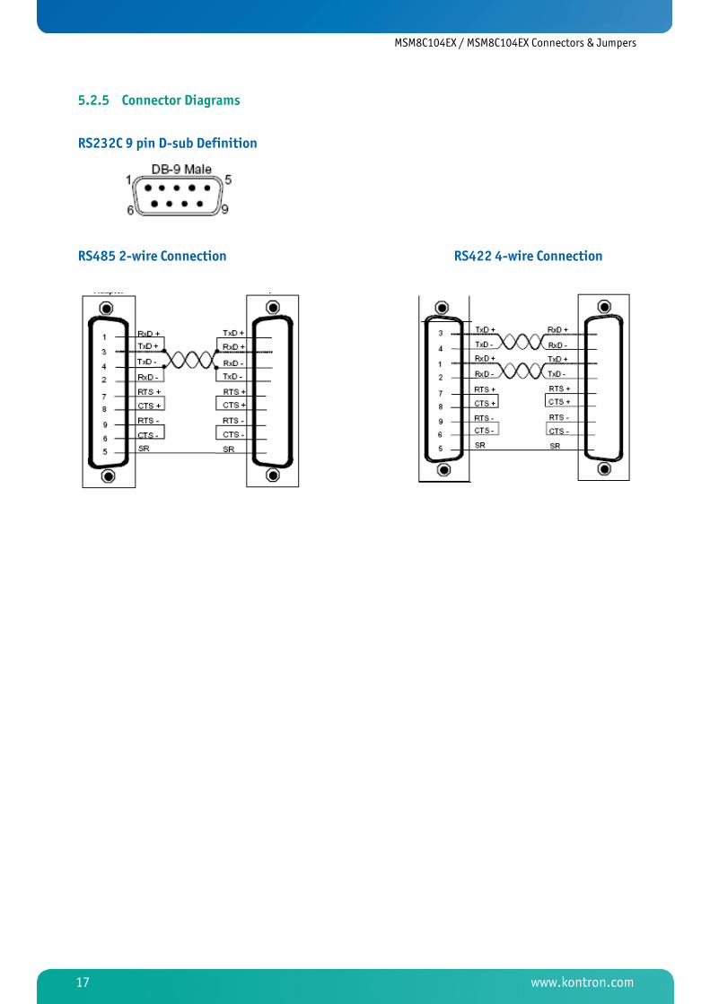
5.2.5 Connector Diagrams
RS232C 9 pin D-sub Definition
RS485 2-wire Connection RS422 4-wire Connection
MSM8C104EX / MSM8C104EX Connectors & Jumpers
www.kontron.com 18
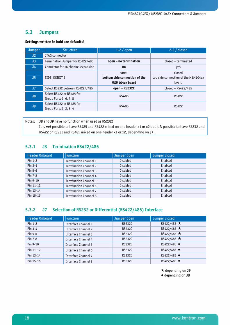
5.3 Jumpers
Settings written in bold are defaults!
Jumper Structure 1-2 / open 2-3 / closed
J2 JTAG connector
J3 Termination Jumper for RS422/485 open = no termination closed = terminated
J4 Connector for 16 channel expansion no yes
J5 SIDE_DETECT 2
open
bottom side connection of the
MSM104ex board
closed
top side connection of the MSM104ex
board
J7 Select RS232 between RS422//485 open = RS232C closed = RS422/485
J8 Select RS422 or RS485 for
Group Ports 5, 6, 7, 8 RS485 RS422
J9 Select RS422 or RS485 for
Group Ports 1, 2, 3, 4 RS485 RS422
Notes: J8 and J9 have no function when used as RS232!
It is not possible to have RS485 and RS422 mixed on one header x1 or x2 but it is possible to have RS232 and
RS422 or RS232 and RS485 mixed on one header x1 or x2, depending on J7.
5.3.1 J3 Termination RS422/485
Header Onboard Function Jumper open Jumper closed
Pin 1-2 Termination Channel 1 Disabled Enabled
Pin 3-4 Termination Channel 2 Disabled Enabled
Pin 5-6 Termination Channel 3 Disabled Enabled
Pin 7-8 Termination Channel 4 Disabled Enabled
Pin 9-10 Termination Channel 5 Disabled Enabled
Pin 11-12 Termination Channel 6 Disabled Enabled
Pin 13-14 Termination Channel 7 Disabled Enabled
Pin 15-16 Termination Channel 8 Disabled Enabled
5.3.2 J7 Selection of RS232 or Differential (RS422/485) Interface
Header Onboard Function Jumper open Jumper closed
Pin 1-2 Interface Channel 1 RS232C RS422/485 �
Pin 3-4 Interface Channel 2 RS232C RS422/485 �
Pin 5-6 Interface Channel 3 RS232C RS422/485 �
Pin 7-8 Interface Channel 4 RS232C RS422/485 �
Pin 9-10 Interface Channel 5 RS232C RS422/485 ‚
Pin 11-12 Interface Channel 6 RS232C RS422/485 ‚
Pin 13-14 Interface Channel 7 RS232C RS422/485 ‚
Pin 15-16 Interface Channel 8 RS232C RS422/485 ‚
� depending on J9 ‚ depending on J8

MSM8C104EX / LEDs
www.kontron.com 19
6 LEDs
Status Indicators
The MSM8C104ex contains onboard diagnostic indicators. There are 2 different indicator types:
1. Eight yellow LEDs show the current serial port configuration. If the LED is on, the port is configured as a standard RS232C serial port. If the LED is off, the port is configured as a standard RS422/RS485 serial port.
2. The green LEDs near the PC/104-Plus connector show the presence of the core voltages needed on the board. If the LED is on, the voltage is present.

MSM8C104EX / Driver Installation & Settings
www.kontron.com 20
7 Driver Installation & Settings 7.1 Driver Installation on Windows XP
The following instructions outline how to install the MSM8C104EX on a computer running Windows XP.
1. After inserting the MSM8C104EX into the PCI/104-Express slot, turn on the system. A "Found New Hardware Wizard" will appear. Insert the Driver-CD into the drive as requested. Select "Install from a list or specific location (Advanced)". Select "Next".
2. Click "Search for the best driver in these locations". Choose "Select removable media (floppy, CD-ROM)" and "Include this location in the search". Type "D:\MSM8C\Drivers\Win2K-XP", where D is the drive letter of the CD ROM. Now select "Next".
MSM8C104EX / Driver Installation & Settings
www.kontron.com 21
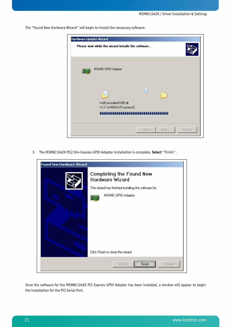
The "Found New Hardware Wizard" will begin to install the necessary software.
3. The MSM8C104EX PCI/104-Express GPIO Adapter installation is complete. Select "Finish".
Once the software for the MSM8C104EX PCI Express GPIO Adapter has been installed, a window will appear to begin
the installation for the PCI Serial Port.

MSM8C104EX / Driver Installation & Settings
www.kontron.com 22
4. Select "Install from a list or specific location (Advanced)". Select "Next."
5. Click "Search for the best driver in these locations". Choose "Select removable media (floppy, CD-ROM)" and "Include this location in the search". Type "D:\MSM8C\Drivers\Win2K-XP", where D is the drive letter of the CD ROM. Now select "Next".

MSM8C104EX / Driver Installation & Settings
www.kontron.com 23
The "Found New Hardware Wizard" will begin to install the necessary software.
6. A window will appear indicating that the software for the MSM8C104EX has not passed Windows Logo testing. Select "Continue Anyway".

MSM8C104EX / Driver Installation & Settings
www.kontron.com 24
7. The MSM8C104EX PCI/104-Express Multiport Serial Adapter installation is complete. Select "Finish".
Once the software for the MSM8C104EX PCI/104-Express Multiport Serial Adapter has been installed, a window will
appear to begin the installation for the MSM8C104EX PCI/104-Express UART Port.
8. Select "Install from a list or specific location (Advanced)". Select "Next."
MSM8C104EX / Driver Installation & Settings
www.kontron.com 25
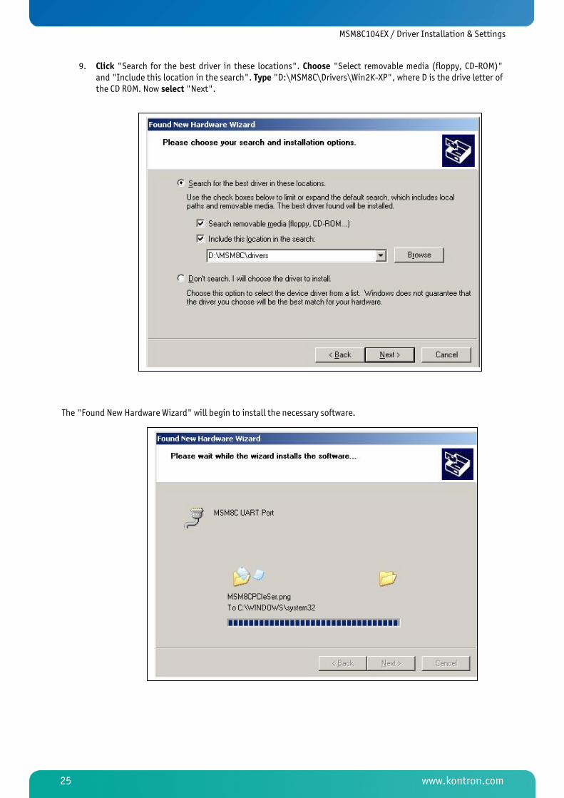
9. Click "Search for the best driver in these locations". Choose "Select removable media (floppy, CD-ROM)" and "Include this location in the search". Type "D:\MSM8C\Drivers\Win2K-XP", where D is the drive letter of the CD ROM. Now select "Next".
The "Found New Hardware Wizard" will begin to install the necessary software.

MSM8C104EX / Driver Installation & Settings
www.kontron.com 26
10. A window will appear indicating that the software for the MSM8C104EX has not passed Windows Logo testing. Select "Continue Anyway".
11. The MSM8C104EX PCI/104-Express UART Port installation is complete. Select "Finish".
MSM8C104EX / Driver Installation & Settings
www.kontron.com 27
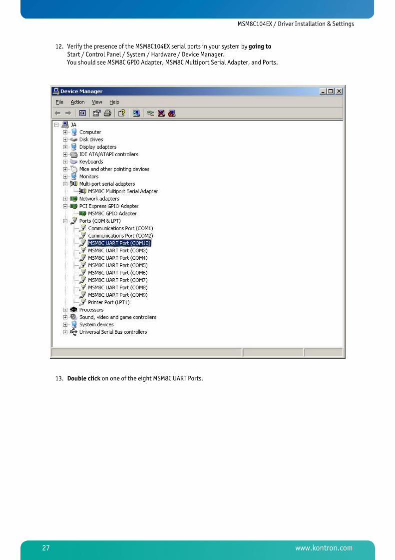
12. Verify the presence of the MSM8C104EX serial ports in your system by going to Start / Control Panel / System / Hardware / Device Manager. You should see MSM8C GPIO Adapter, MSM8C Multiport Serial Adapter, and Ports.
13. Double click on one of the eight MSM8C UART Ports.

MSM8C104EX / Driver Installation & Settings
www.kontron.com 28
14. Click on the "General" tab to see that your device is working properly.

MSM8C104EX / Driver Installation & Settings
www.kontron.com 29
7.2 Port Settings
From the "Device Manager", you can access individual port settings by double-clicking the appropriate MSM8C104EX
UART Port and clicking the "Settings" tab. Port settings include baud rate, data bits, parity, stop bits and flow
control.
Hardware Configuration for RS422 – select RS232.
Hardware Configuration for RS485 – select RS422/485 and set RS485 settings to "active high".
7.2.1 COM Port Number
The driver supports the ability to change COM port names, also known as COM port mapping.
For example , specifying COM3 would set the COM name for the selected port toCOM3.
Note: Ensure the COM name selected is not already in use or the port may not respond properly.

MSM8C104EX / Driver Installation & Settings
www.kontron.com 30
7.2.2 FIFOs
Choose the "FIFOs" tab, located at Start / Control Panel / System / Hardware / Device Manager / Ports. The settings
for the FIFO buffers can be selected here.
Receive and Transmit FIFO Settings
These sliders adjust the size of the UART FIFO levels used by the MSM8C104EX UART ports. More buffering can be
obtained the further to the right the slider is moved. This results in higher throughput and lower load on the system.
Note: High buffer levels can cause communication problems with some applications.

MSM8C104EX / Assembly Views
www.kontron.com 31
8 Assembly Views
8.1 Top Side

MSM8C104EX / Assembly Views
www.kontron.com 32
8.2 Bottom Side

MSM8C104EX / Appendix A: Architecture Information
www.kontron.com 33
9 Appendix A: Architecture Information
The following sources of information can help you better understand PC architecture.
9.1 Buses
9.1.1 ISA, Standard PS/2 – Connectors
» AT Bus Design: Eight and Sixteen-Bit ISA, E-ISA and EISA Design, Edward Solari, Annabooks, 1990, ISBN 0-929392-08-6
» AT IBM Technical Reference Vol 1&2, 1985
» ISA & EISA Theory and Operation, Edward Solari, Annabooks, 1992, ISBN 0929392159
» ISA Bus Specifications and Application Notes, Jan. 30, 1990, Intel
» ISA System Architecture, Third Edition, Tom Shanley and Don Anderson, Addison-Wesley Publishing Company, 1995, ISBN 0-201-40996-8
» Personal Computer Bus Standard P996, Draft D2.00, Jan. 18, 1990, IEEE Inc
» Technical Reference Guide, Extended Industry Standard Architecture Expansion Bus, Compaq 1989
9.1.2 PCI/104
» Embedded PC 104 Consortium
» The consortium provides information about PC/104 and PC/104-Plus technology. You can search for information about the consortium on the Web.
» PCI SIG
» The PCI-SIG provides a forum for its ~900 member companies, who develop PCI products based on the specifications that are created by the PCI-SIG. You can search for information about the SIG on the Web.
» PCI & PCI-X Hardware and Software Architecture & Design, Fifth Edition, Edward Solari and George Willse, Annabooks, 2001, ISBN 0-929392-63-9.
» PCI System Architecture, Tom Shanley and Don Anderson, Addison-Wesley, 2000, ISBN 0-201-30974-2.
9.2 General PC Architecture
» Embedded PCs, Markt&Technik GmbH, ISBN 3-8272-5314-4 (German)
» Hardware Bible, Winn L. Rosch, SAMS, 1997, 0-672-30954-8
» Interfacing to the IBM Personal Computer, Second Edition, Lewis C. Eggebrecht, SAMS, 1990, ISBN 0-672-22722-3
» The Indispensable PC Hardware Book, Hans-Peter Messmer, Addison-Wesley, 1994, ISBN 0-201-62424-9
» The PC Handbook: For Engineers, Programmers, and Other Serious PC Users, Sixth Edition, John P. Choisser and John O. Foster, Annabooks, 1997, ISBN 0-929392-36-1
MSM8C104EX / Appendix A: Architecture Information
www.kontron.com 34
9.3 Ports
9.3.1 RS232 Serial
» EIA�232�E standard
» The EIA-232-E standard specifies the interface between (for example) a modem and a computer so that they can exchange data. The computer can then send data to the modem, which then sends the data over a telephone line. The data that the modem receives from the telephone line can then be sent to the computer. You can search for information about the standard on the Web.
» RS232 Made Easy: Connecting Computers, Printers, Terminals, and Modems, Martin D. Seyer, Prentice Hall, 1991, ISBN 0-13-749854-3
» National Semiconductor: The Interface Data Book includes application notes. Type "232" as search criteria to obtain a list of application notes. You can search for information about the data book on National Semiconductor's Web site.
9.3.2 Serial ATA
Serial AT Attachment (ATA) Working Group. This X3T10 standard defines an integrated bus interface between disk
drives and host processors. It provides a common point of attachment for systems manufacturers and the system. You
can search for information about the working group on the Web. We recommend you also search the Web for
information on 4.2 I/O cables, if you use hard disks in a DMA3 or PIO4 mode.
9.3.3 USB
USB Specification
USB Implementers Forum, Inc. is a non-profit corporation founded by the group of companies that developed the
Universal Serial Bus specification. The USB-IF was formed to provide a support organization and forum for the
advancement and adoption of Universal Serial Bus technology. You can search for information about the standard on
the Web.
9.4 Programming
» C Programmer's Guide to Serial Communications, Second Edition, Joe Campbell, SAMS, 1987, ISBN 0-672-22584-0
» Programmer's Guide to the EGA, VGA, and Super VGA Cards, Third Edition, Richard Ferraro, Addison-Wesley, 1990, ISBN 0-201-57025-4
» The Programmer's PC Sourcebook, Second Edition, Thom Hogan, Microsoft Press, 1991, ISBN 1-55615-321-X
» Undocumented PC, A Programmer's Guide to I/O, CPUs, and Fixed Memory Areas, Frank van Gilluwe, Second Edition, Addison-Wesley, 1997, ISBN 0-201-47950-8

MSM8C104EX / Appendix B: Document Revision History
www.kontron.com 35
10 Appendix B: Document Revision History Revision Date Edited by Changes
100 04.Jan.2010 WAS Changed to new Kontron Corporate Design from DLAG V1.1A
101 27.Jan.2010 WAS Formatting changes to fit A4 paper. Kontron-formatted title photo.
102 23.Mar.2010 WAS Minor formatting changes to Pgs 9, 10, 16, 17, 32, 33, 39
103 02.Feb.2011 MEG/WAS Description of Jumpers 8 & 9 added / Configurations of RS422 & RS485
MSM8C104EX / Index
www.kontron.com 36
11 Index
A
Architecture Information .................................. 33
Assembly Views .............................................. 31
Bottom ...............................................................32
Top.....................................................................31
B
Benefits .......................................................... 8
Bus ................................................................ 9
C
COM Port Number ............................................ 29
Connectors
COM1-4 ...............................................................13
COM5-8 ...............................................................14
Diagrams.............................................................17
ISA.....................................................................33
PCI .....................................................................14
PCI/104-Express Bus .............................................15
PS/2 ...................................................................33
Connectors & Jumpers ..................................... 12
Copyright ........................................................ 4
D
Dimensions...................................................... 9
Document ....................................................... 4
Document Revision History ............................... 35
Documentation................................................. 8
Driver Installation........................................... 20
E
Environmental Protection ................................... 5
F
FIFO Settings ................................................. 30
FIFOs............................................................ 30
Full Duplex Mode .............................................11
Functionality ................................................... 8
G
GPIO Adapter ..................................................21
H
Half Duplex Mode ............................................11
Humidity ........................................................ 9
I
Interfaces
Electrical .............................................................11
RS232 .................................................................11
RS232 or RS422/485..............................................18
RS422/485 ..........................................................11
J
Jumpers ........................................................18
L
LEDs .............................................................19
Line Bias/Termination ......................................11
M
Multi-drop Mode..............................................11
Multiport Serial Adapter....................................24
O
Ordering Information ........................................ 8
P
PCI Serial Port.................................................21
PCI/104.........................................................33
MSM8C104EX / Index
www.kontron.com 37
Pinouts ......................................................... 13
Port Settings.................................................. 29
Ports ............................................................ 34
Programming ................................................. 34
R
RoHS.............................................................. 5
RS232 Serial .................................................. 34
RS422 Hardware Configuration .......................... 29
RS485 Hardware Configuration .......................... 29
S
Serial ATA...................................................... 34
Shock ............................................................. 9
Specifications .................................................. 9
Electrical ...............................................................9
Environmental........................................................9
Functional .............................................................9
UART ..................................................................10
SQS................................................................ 7
Standards........................................................ 4
Status Indicators ............................................ 19
Swiss Association for Quality and Management
Systems ....................................................... 7
Swiss Quality ................................................... 6
T
Technical Support............................................. 5
Termination RS422/485....................................18
Trademarks ..................................................... 4
U
UART ............................................................10
UART Port ......................................................24
USB..............................................................34
V
Vibration ........................................................ 9
W
Warranty ........................................................ 4
WEEE ............................................................. 6
Windows XP ....................................................20
MSM8C104EX / Index
www.kontron.com 38
Corporate Offices
Europe, Middle East & Africa Kontron AG Oskar-von-Miller-Strasse 1 85386 Eching/Munich Germany Tel.: +49 (0)8165/ 77 777 Fax: +49 (0)8165/ 77 219 [email protected]
Switzerland Kontron Compact Computers AG Nordstrasse 11/F CH – 4542 Luterbach Switzerland Tel.: +41 (0)32 681 58 00 Fax: +41 (0)32 681 58 01 [email protected]