KC / KWR Coping Robot and Welding Robot ... / KWR Coping Robot and Welding Robot 4 The complete...
14
If Steel is Your Deal! KC / KWR Coping Robot and Welding Robot
Transcript of KC / KWR Coping Robot and Welding Robot ... / KWR Coping Robot and Welding Robot 4 The complete...

1www.kaltenbach.com
If St
eel i
s You
r Dea
l!
KC / KWRCoping Robot andWelding Robot

4
The complete KALTENBACH program for pro�le and beam processing

5www.kaltenbach.com

48
The machine was speci�cally developed for the coping of H, U and L pro�les
as well as of rectangular tubing. The proven robot of the German manufacturer
KUKA works extremely �exibly, thanks to the data technology of KALTENBACH
which is precisely aligned to steel pro�le machining. Compared to manual
coping, the machining costs are substantially reduced.
Applications: steel fabrication, steel service center
Advantages at a glance � Work area (w x h): 1200 × 500 mm
� Portal frame machine design in robust welded construction to permit the incorporation of an industrial robot in swivel-joint construction
� Coping of H, U and L sections in addition to rectangular tubing and �at material
� Tried and tested six-axis KUKA robot
� Partial programming possibility via NC-DSTV �les, integrated drawing program or macros
� Autogenous Gas and/or Plasma Cutting Procedure
The Professional One
KC 1201
Profile Processing Robot: Coping at the Highest Level

49www.kaltenbach.com
Plat
epro
cess
ing
Cent
ers
Copi
ng/W
eldin
gRo
bots
Circ
ular
Saw
ing
Mac
hine
sSe
rvic
eAu
tom
atio
nPa
intin
gSy
stem
sSh
otbl
ast
Syst
ems
Punc
h-/S
hear
M
achi
nes
Drill
ing
Mac
hine
sBa
nd S
awin
gM
achi
nes
Technical Data KC 1201Machine dimension (L X W X H) mm 2.850 x 4.400 x 3.220
Machine Weight kg 5.900
Working range mm 1.200 x 450
working range Pro�le mm 1.200 x 450
Bevel angle max. Degrees 45
Autogenous Gas and/or Plasma Cutting Procedure• Universally-implementable autogenous
gas cutting procedure (standard)• In addition to autogenous gas cutting, a
high-performance plasma cutting machi-ne can optionally be used
• The autogenous gas cutter can be replaced by a plasma cutting machine through simple modi�cation
Processing Variants• Additional gas cutting of a workpiece that
has already been cut to length or drilled• Workpiece is �ame cut to length:• Straight cut, web �ange mitre or
combined mitre (two-angle cut)• Circular and slotted holes• Chamfers (welding edge preparation)• Longitudinal cuts• Castellated beams
Coping Robot with Eight Axes• Six-axis KUKA robot mounted to a portal
crossbeam, moving over a seventh linear robot axis transversely to the workpiece
• Material positioning via the 8th robot axis
KC 1201

50
It rarely happens that with more accuracy, the productivity also goes up:
The newly developed robot welding system automates the welding process
with the same high quality of weld. Hence, it is clearly superior to manual
processing. The system is designed for the welding of sub-assemblies with
steel beams and accessories. Automatic generation of the robot programm
via WISCON interface.
Applications: steel fabrication
The Precise One
KWR 601
Robot Welding System for Processing of Assemblies with Beams and Welded Attachments
Advantages at a glance � Dimensions (l x w x h – incl. suction device): 20.000 x 6.600 x 4.800
� Reduction of the overall time required for welding to 1/3 to 1/5 of that of conventional processes, depending on the nature of the parts
� Consistently high welding seam quality
� Optimum integration of the welding process in the company-interal �ow of materials
� Automatic documentation of process parameters and time recording
� Widening the scopw of CAD/CAM integration to include the welding process

51www.kaltenbach.com
Plat
epro
cess
ing
Cent
ers
Circ
ular
Saw
ing
Mac
hine
sSe
rvic
eAu
tom
atio
nPa
intin
gSy
stem
sSh
otbl
ast
Syst
ems
Punc
h-/S
hear
M
achi
nes
Copi
ng/W
eldin
gRo
bots
Drill
ing
Mac
hine
sBa
nd S
awin
gM
achi
nes
KWR 601
Technical data KWR 601Pro�le range mm Double-T-beams
Beam width min. / max. mm 160 / 620
Beam height min. / max. mm 80 / 310
Flange thickness min. / max mm 8 / 40
Web thickness min. / max. mm 5,5 / 25
Part length min. / max. mm 1.600 / 8.000
Beam weight max. kg/m 280
Part weight max. kg/m 400
Welding technique:
- One-pass – three-pass welding Puls, MAG
- Throat thickness max. (a) mm 8
- Wire thickness mm 1,2
Automatic generation of the robot programm• Acquisition of 3D CAD data is based
on the welding assembly component interface for steel fabrication taken from NC-DSTV and an XML extension
Measurement of components via the welding robot• Form scanning: determination of the
tolerances of the primary component• Seam location: determination of the start
and end point of the seam• Steam tracking: automatic tracking of the
welding seam (tolerance compensation)
Workpiece positioner• Transport speed 35 m/minute• Minimum distance between both
positioners: 500 mm• Rotation centre above �oor: 950 mm• Swivel-/rotation diameter: 1400 mm

68
L o g i s t i c + P r o c e s s C o n t r o l
Huge potential for increasing e�ciency in steel machining
We know how: KALTENBACH Logistic + Process Control
Everything in Motion
Customer requirements
• Plate processing• Profile processing • Tube processing
• Sawing• Drilling• Stamping
Planning Logistics
Production process
• CAD/CAM-Systems• Data processing
• Transport• Storage• Handling

69www.kaltenbach.com
L o g i s t i c + P r o c e s s C o n t r o lCi
rcul
ar S
awin
gM
achi
nes
Serv
ice
Auto
mat
ion
Pain
ting
Syst
sem
sSh
otbl
ast
Syst
ems
Punc
h-/S
hear
M
achi
nes
Plat
epro
cess
ing
Cent
ers
Copi
ng/W
eldin
gRo
bots
Drill
ing
Mac
hine
sBa
nd S
awin
gM
achi
nes
The automatic production control with LPC (Logistic Process Control) systems is already widespread in the manufacturing industry. Up to now in steel machining, however, only stand-alone solutions have been implemented in steel construction and the steel trade and these only automate individual machining steps. As one of the �rst suppliers to do so, KALTENBACH has now developed the KLPC (KALTENBACH Logistic Process Control) system which fully automates all machining steps – such as sawing, drilling, �ame-cutting, coping to shotblasting and painting – as well as the transport of the work piece between the respective machining processes, and visualises them in real time.
Via the DSTV interface, the KLPC system can adopt CAD/CAM data directly from higher-level ERP systems. At the same time, it visualises and reports the processing status of each job in real time back to the ERP system. The production manager thus gains for the �rst time a complete overview of the current processes in the machining and thus optimises existing machine capacities and the utilisation of production.
With the KLPC system, KALTENBACH is heralding a new era in steel machining. On the one hand, it o�ers huge potential for increasing e�ciency with the automation and optimisation of processes.
On the other, it creates the prerequisites in the �rst place for capturing the entire machining process, visualising it and thus gaining a detailed overview of it. Every company that uses KLPC can thus draw up more comprehensive and detailed plans and generate a clear competitive advantage with this.
How the right material and
associated information reaches the right
location at the right time and how, when
and where the current process data gets
reported back?
Key issues
• Shearing• Coping• Shot Blasting
• Painting• Measuring• Transport
Production process
Logistics Construction site
• Transport• Storage• Handling
• Fastening• Mounting• Handling

Keep it Flowing !
72
Advantages at a glance � Highest accuracy and productivity
� All from one source – for highest production reliability
� Modular and future-proof system
� A variety of automation levels from semi to full automation for complete processing lines
� Heavy and robust design
There’s no production without transport equipment. Sturdy roller conveyor
systems and cross transport systems guarantee an e�cient �ow of
materials in plate and steel processing. An extensive range of measuring
equipment generates full �exibility and required dimensional accuracy.
Cross Transport by Means of Drag Chains• Material stock in heavy-duty steel
construction• Sliding rails of synthetic material
(polyamide) for low-noise material cross transport
• Drag chains with transport claws• Drive system with continuously-variable
frequency-controlled gear motor
Cross Transport by Means of Lift-and-Carry System• Hydraulic liftable and lowerable lifting
beams running in both directions
• Drive system with continuously-variable frequency-controlled gear motor
Conveyor Roller System• Modular Expandable
• Executed in welded construction with maintenance-free, ball-bearing conveyor rollers of solid material
• Roller-conveyor drive on the feed and removal sides with frequency-controlled gear motor
Fully automatic Plate Processing centre• Automatic part removal and sorting
• Flexible programmed sorting location
• The size of the sorting range can be customised
Transport & Measuring
Efficient Flow of Materials is the Basis for Ultimate Productivity

73www.kaltenbach.com
Circ
ular
Saw
ing
Mac
hine
sSe
rvic
eAu
tom
atio
nPa
intin
gSy
stse
ms
Shot
blas
t Sy
stem
sPu
nch-
/She
ar
Mac
hine
sPl
atep
roce
ssin
g Ce
nter
sCo
ping
/Weld
ing
Robo
tsDr
illin
gM
achi
nes
Band
Saw
ing
Mac
hine
s
T13-Silencer• Contributes to enhanced occupational
safety and the protection of personnel and the environment
• Low-Noise Material Cross Transport
• Fully-automatic control
Marking System • Fast marking process for applying letters
and numerals
• Up to 22 characters without material movement
• Can be integrated into fully-automated handling processes
• Imprint still clearly visible after galvani-zing or painting
Contour Marking• Application of reference boundaries for
welding add-on pieces
• DSTV-Data import
• Use of high-speed carbide tools
• In addition to the three drill axis - marking from the bottom (4th axis)
Pusher Measuring System • Positioning drive through servo motor
with absolute rotary encoder
• Automatic NC positioning via machine software
• Hydraulic height adjustment for measu-ring various pro�le cross-sections
Length Stop Measuring System• Positioning drive through servo motor
with absolute rotary encoder
• Automatic NC positioning via machine software
• Rapid pivoting of the squaring arm
Autosorter• Process-assured full automation of the
feed side in pro�le handling
• Variable sorting positions possible
• For parts with mitre or straight cut from a length of 50 mm and up to a width of 1000 mm

74
KALTENBACH sets new standards in the area of customer service: Remote
maintenance of all equipment ensures the fastest possible repair in case of
malfunction, and therefore the highest possible equipment availability.
Our specialists can be reached via a service hotline that o�ers professional
support worldwide. A dense network of national and international service
partners in over 40 countries ensures the presence at short notice of a skilled
expert when needed. Our parts service ensures that users can get the
spare parts they need for their machines even after many years.
Advantages at a glance � Over 150 service technicians are available at more than 40 locations worldwide
� 1st level support through the local service organization
� 2nd level support through the specialists at the service helpdesk
� INITIAL ASSEMBLY: Consulting, Project planning, Organization, On-schedule, professional assembly/initial operation, Training
� Breakdown prevention through maintenance contracts (preventative maintenance)
� Worldwide express delivery of necessary replacement parts and tools
“From practical experience – to be put to practical use!“
A Service Network that is there for You – Right from the Start!
The Originals
Service
Find your local Service Partner:
www.kaltenbach.com
Originale die passen!
75www.kaltenbach.com
Circ
ular
Saw
ing
Mac
hine
sSe
rvic
eAu
tom
atio
nPa
intin
gSy
stse
ms
Shot
blas
t Sy
stem
sPu
nch-
/She
ar
Mac
hine
sPl
atep
roce
ssin
g Ce
nter
sCo
ping
/Weld
ing
Robo
tsDr
illin
gM
achi
nes
Band
Saw
ing
Mac
hine
s
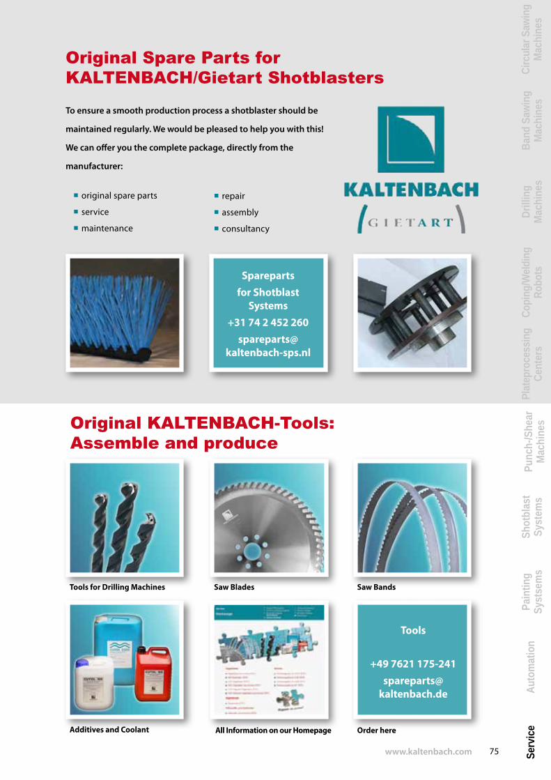
Tools for Drilling Machines Saw Blades Saw Bands
Additives and Coolant
Original KALTENBACH-Tools: Assemble and produce
Tools
+49 7621 175-241spareparts@
kaltenbach.de
Original Spare Parts forKALTENBACH/Gietart Shotblasters
To ensure a smooth production process a shotblaster should be
maintained regularly. We would be pleased to help you with this!
We can o�er you the complete package, directly from the
manufacturer:
� original spare parts
� service
� maintenance
Sparepartsfor Shotblast
Systems+31 74 2 452 260
spareparts@ kaltenbach-sps.nl
� repair
� assembly
� consultancy
Order hereAll Information on our Homepage

Robotic Coping Machines
Band Sawing and Circular Sawing
MachinesDrilling
Machines
Measuring Systems
Shotblast system
Punching/Shearing Machines
Plate Processing CentersPainting
System
Transport Systems
Robot Welding System
Kaltenbach GmbH + Co. KG PP.O. Box 17 40 D-79507 Lörrach, Germany Blasiring 4 D-79539 Lörrach, Germany
Phone: +49 (0) 7621 / 175-0 Fax: +49 (0) 7621 / 175-477
[email protected] www.kaltenbach.com