Kawasaki Z650 Restoration Project - KZ650.info Z650 Restoration Project Like many other fans of...
22
Untitled Document Kawasaki Z650 Restoration Project Like many other fans of Japanese bikes of the seventies I've always had a soft spot for the Kawasaki Z650. I reckon the middleweight Zed is one of the best designs to come from Japan, and I'd place it in the top three best Japanese classic bikes along with Suzuki's GS750 and the mighty Z1. And despite the fact that I have owned and run three Z650s and used to work at a Kawasaki dealership this isn't all down to rose tinted specs! Many Jap classic fans appreciate the timeless engineering, performance and styling of the Z650, and examples of the bike in good nick are becoming highly sought after. It was no real surprise, therefore, when I had a call from Mark who asked me to help him track down a good example. He'd viewed several tatty Zs but had really set his heart on owning a mint example, and between us we decided his best option was to buy the best bike he could find and then spend some time and money putting it into top notch order. When Mark finally took the plunge he went for this 1980 model Z650F1 finished in Luminous Dark Blue. Though he'd really set his heart on an earlier Z650C model (which came with a rear disc brake), this F1 seemed in excellent mechanical condition and only needs some cosmetic tidying up to make it really smart. Or that's what I thought. Here's how the project went... Part 1 - stripping down the bike http://www.bikerworld.co.uk/tech/Z650_restoration/index.html (1 of 2)17.01.2005 01:59:25
Transcript of Kawasaki Z650 Restoration Project - KZ650.info Z650 Restoration Project Like many other fans of...

Untitled Document
Kawasaki Z650 Restoration Project
Like many other fans of Japanese bikes of the seventies I've always had a soft spot for the Kawasaki Z650. I reckon the middleweight Zed is one of the best designs to come from Japan, and I'd place it in the top three best Japanese classic bikes along with Suzuki's GS750 and the mighty Z1. And despite the fact that I have owned and run three Z650s and used to work at a Kawasaki dealership this isn't all down to rose tinted specs! Many Jap classic fans appreciate the timeless engineering, performance and styling of the Z650, and examples of the bike in good nick are becoming highly sought after.
It was no real surprise, therefore, when I had a call from Mark who asked me to help him track down a good example. He'd viewed several tatty Zs but had really set his heart on owning a mint example, and between us we decided his best option was to buy the best bike he could find and then spend some time and money putting it into top notch order. When Mark finally took the plunge he went for this 1980 model Z650F1 finished in Luminous Dark Blue. Though he'd really set his heart on an earlier Z650C model (which came with a rear disc brake), this F1 seemed in excellent mechanical condition and only needs some cosmetic tidying up to make it really smart. Or that's what I thought. Here's how the project went...
Part 1 - stripping down the bike
http://www.bikerworld.co.uk/tech/Z650_restoration/index.html (1 of 2)17.01.2005 01:59:25

Untitled Document
Part 2 - sorting out the bits
Part 3 - spark erosion and the great brake caliper chase
http://www.bikerworld.co.uk/tech/Z650_restoration/index.html (2 of 2)17.01.2005 01:59:25

Untitled Document
1. To begin with I've removed the engine oil drain plug and placed a drip tray under the engine. While the oil drains out I can then disconnect and remove the battery. The battery was already too flat to turn the bike over so I'll pop it on charge and see if it can be saved, but I expect to replace it with a new one for the rebuild. Next I've removed the seat pivot pins and lifted the seat off.
2. Though I've siphoned most of it out, there's still a little fuel in the tank. The Z650 uses a vacuum operated tap with three positions; "ON", "PRI" and "RES". Both the "ON" and "RES" positions should only flow fuel with the engine running, so I can safely disconnect the pipes from the tap. Leaving the tap on "PRI", though, would by-pass the vacuum and allow fuel to flow. Note the two rubber pipes, the large bore pipe is the fuel feed to the carbs, the small bore pipe is the vacuum control for the tap.
3. The Z650 tank is simply push fitted into a rubber grommet on the frame, so I can now pull it up and backwards to release it from the two rubber bobbins at the headstock. The tank gets wrapped up and stored for safety for the time being.
4. I've opted to start to strip the cycle parts off the bike from the back end and work forwards. First is the trademark ducktail which is rubber mounted to the frame at four points. With the four M6 bolts removed it lifts clear.
5. I've disconnected the wiring for the taillight and winkers, and then removed the rear winkers, each of which is located in a rubber grommet on the frame by a single nut. The wiring has a terminal block for the taillight and is colour coded, so will be easy enough to re-connect for the rebuild. Now four M6 bolts hold the rear fender section to the frame, and with those released the fender comes away with the taillight assembly.
6. Two more M6 nuts and bolts clamp the front section of the rear fender to the frame. With these removed the fender unclips from its frame lugs and waggles free. Incidentally as a former Kawasaki parts man I still refer to these bits as "rear fender rear" and "rear fender front", so no apologies for not calling them mudguards. This bike is a US import after all!
http://www.bikerworld.co.uk/tech/Z650_restoration/stripdown/index.html (1 of 2)17.01.2005 01:59:43

Untitled Document
7. On the left hand side of the frame now, the major electrical components are mounted on this plate which in turn is rubber mounted to the side of the battery tray. Again everything is colour coded so it's easy enough to disconnect all the wiring and unbolt the solenoid, regulator and flasher relay and store them away. Then the mounting plate comes off, followed by the battery tray itself which lifts up and out between the seat rails.
on to page two
http://www.bikerworld.co.uk/tech/Z650_restoration/stripdown/index.html (2 of 2)17.01.2005 01:59:43

Untitled Document
8. Behind the electrics mounting plate lives this wiring connector which takes live power from the battery positive terminal to the fuse box on the other side of the bike. Some of the insulation looks dodgy on this wire and the sleeves on the snap connector have almost melted at some time in the past. I make a mental note to go over the harness carefully before rebuilding the bike - this kind of damage can easily be repaired if its in a small area but any signs of melted insulation in the main harness means replacing the whole thing.
9. Removing the carbs is arguably the trickiest part of the stripdown. The still air box, which is now free of its mounting points on the battery carrier, can be shoved backwards half an inch to give a little more room, but the inlet rubbers between the carbs and filter have hardened with age and exposure to petrol vapour and lost much of their flexibility. A few minutes of determined waggling finally gets them free without damaging anything.
10. With the carbs out of the way the still air box pushes forwards between the frame rails and comes out sideways. The still air box is connected up to the crankcase with a short 90 degree hose at the bottom, and on this bike also with a large bore rubber pipe pushed into a grommet at the top. Even now space is tight, and I've had to remove the air filter cap to clear the frame. There's also a small plastic air baffle plate mounted to the frame forward of the seat nose which has to be taken off first.
11. The ignition coils are mounted onto either side of the frame, the left hand coil firing the middle two cylinders (2&3), and the right hand coil firing the two outers (1&4). Again the wiring can simply be unclipped as everything is colour coded.
12. With the coils removed the full extent of the environmental pipework is revealed. This assembly of hoses and canister allows the engine to feed blow by gasses from the top of the cambox back into the still air box where they can be sucked back into the engine and burned. Necessary for US environmental legislation, UK bikes came without all of this and had cleaner lines on the top of the engine. We could convert the bike to UK spec with a new cambox, blanking off the extra hole in the still air box, but its probably easier to simply replace all this lot on the rebuild. It's clutter, but it doesn't do any harm.
13. Next, the headlamp unit comes out of the shell and I can unclip all the wiring terminal blocks to remove the main harness from the bike. One or two terminal blocks are showing signs of internal corrosion, and this one has clearly been butchered in the past. It's still serviceable if correctly insulated but I'd rather replace it for the rebuild.
http://www.bikerworld.co.uk/tech/Z650_restoration/stripdown/page2.html (1 of 2)17.01.2005 01:59:48

Untitled Document
14. Up at the front end the headlamp shell is retained by the winker stems, which pass through rubber grommets in the headlamp brackets and each have single nuts at the back. With the winkers removed the shell lifts clear.
15. The clocks, warning light cluster and ignition switch can be removed in one piece. After undoing the speedo and tacho cables from the clocks two nuts secure the whole assembly into these two bosses at the front of the top yoke. Four conical rubber bushes fit into the holes in the top yoke to rubber mount the whole thing, and each clock is also rubber mounted onto the main bracket.
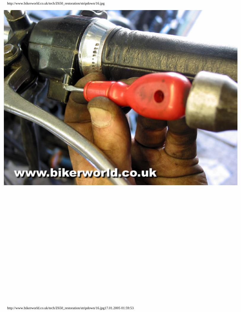
16. The handlebar switches can now be removed from the handlebars. Like most Japanese bikes of the era this Z650 has each switch clamped up with two M5 panhead screws, and like most they have been overtightened into dry threads. Sometimes they will unscrew easily, but quite often they will need some persuasion to shift. This is what old screwdrivers are for. I'd always fit new screws after this kind of butchery, but we plan to replace the whole clusters with UK spec switchgear anyway, which will let us turn the lights off.
on to page three
http://www.bikerworld.co.uk/tech/Z650_restoration/stripdown/page2.html (2 of 2)17.01.2005 01:59:48
http://www.bikerworld.co.uk/tech/Z650_restoration/stripdown/16.jpg
http://www.bikerworld.co.uk/tech/Z650_restoration/stripdown/16.jpg17.01.2005 01:59:53

Untitled Document
17. Mark wants a twin disc set up fitting when the bike is rebuilt. I'll probably be re-building and re-using this left hand caliper, which looks in reasonably good nick. Signs of copper slip on the mounting bolts are very encouraging, but I reserve final judgement until I try to free off the bleed nipple.
18. I'm removing the master cylinder from the handlebars and taking the whole front brake system off as an assembly. Not only does this save me getting brake fluid all over the part stripped bike, it also means I can work on the braking system on the bench later, and can use hydraulic pressure from the master cylinder to pump out the piston from the caliper. A twin disc set up would need a bigger capacity master cylinder, so I probably won't be re-using this one.
19. Next, the exhaust system. Another potential problem area is the eight studs which hold the exhaust front pipes into the cylinder head. Kawasaki specified M6 studs and nuts here and they frequently rust up, sometimes pulling the studs out of the head and sometimes shearing off. On this bike they all unfasten without any problems, possibly reflecting the rain and winter salt free climate this bike has been kept in. At the rear the silencers are supported by bolts passing through the pillion footrest mounts, and I'm taking the weight of the system as I remove them.
20. With all the mountings undone the exhaust system waggles clear of the cylinder head and lifts off as an assembly. The four finned alloy clamps at the top stay on the pipes, but the eight spilt collars which clamp the pipes into the head come free and fall out as the pipes come away.
21. At this stage I'd usually unbolt the engine and lift it out of the frame, removing the forks and suspension later. However the two lower front engine bolts on the left hand side are proving reluctant to free off, and look to be seized solidly into the crankcase. Rather than struggle with these I've decided to strip the wheels, forks and suspension off the frame, then turn the whole plot upside down to give me better access to the two troublesome bolts. To begin with the rear wheel drops out of the back of the swingarm after these two blocks have been removed; no need to remove the wheel spindle. Then the swingarm and rear shockers simply unbolt from the frame.
22. At the sharp end the front wheel is retained in the fork legs with two alloy clamps, again there's no need to remove the wheel spindle at this stage. These clamps can sometimes corrode in place, but these have been copper slipped fairly recently.
http://www.bikerworld.co.uk/tech/Z650_restoration/stripdown/page3.html (1 of 2)17.01.2005 02:00:18

Untitled Document
23. For the time being I'm removing the front forks as an assembly. To begin with the top yoke is retained with a pinch bolt at each fork leg mount, and a pinch bolt at the steering stem. With all three pinch bolts loosened this large chrome bolt can be removed from the top of the steering stem, and the top yoke lifted free.
24. I'm leaving the fork legs clamped into the bottom yoke for now, so only need to remove the steering stem from the headstock to take the whole front end off. The large adjuster nut comes off with a C spanner first, followed by the dust cover and the top cone section of the upper head bearing. The steering stem drops down the headstock as it comes free, and I can then lift the fork assembly out of the frame and put it aside. The Z650s used ball bearings in the headstock rather than the superior taper roller bearings found in later bikes. Aftermarket taper roller kits used to be readily available for these bikes, and I'll be investigating fitting some on the rebuild. In the meantime lots of the steel balls from the bottom bearing have fallen out and rolled away; no problem as I would always fit new ones.
25. With the bike reduced to the engine and main frame cradle its light enough to manhandle upside down to get at the two stubborn engine bolts. Its clear now that they're both seized solid into the crankcase and free in the frame holes. Rather than risk damaging either the frame or crankcase I've managed to flex the frame just far enough away from the engine to get a hacksaw blade into the gap, and slowly and painstakingly cut through the bolts to free the engine. This leaves the remnants of the seized bolts in the crankcase, and I may be looking at getting them removed by spark erosion once the engine is stripped.
And that's enough for now. Next I'll be sorting though the pile of bits and sending the frame and ancillaries away for powder coating.
Dr.Rod
http://www.bikerworld.co.uk/tech/Z650_restoration/stripdown/page3.html (2 of 2)17.01.2005 02:00:18

Untitled Document
Last update I managed to dismantle Marks Kawasaki Z650F1 down into big lumps, and not without some difficulties. The major problem was two of the front engine bolts which were seized solidly into the crankcase, and I had to resort to carefully cutting through them with a hacksaw blade squeezed between the engine and the frame tube in order to get the engine out. Now I've got the bike into smaller bits I can really start work on the renovation. As various bits will have to be sent out for powder coating and plating I've decided to get those bits prepared and sent out first, then I can work on the engine while I wait for them to come back.
1. I've started by separating the cycle parts into piles, sorted according to how they need to be refinished. This sounds easy, but remember it may be some months before it all goes back together again and its worth taking lots of photos and making notes to make sure you have a guide when its time to reassemble everything. These are all the parts for powder coating.
2. To make the job easier for the powder coaters everything has to be degreased and washed before it goes off to them. I'm using a small electric parts washer filled with Millers Millsol Green cleaning solvent. It's a bit smelly, but its a fast and effective way of quickly degreasing parts and is an invaluable workshop resource.
3. The frame is going off for powder coating too, so that also needs to be thoroughly degreased. All the ancillary bits on the frame like seat locks and steering locks must all be removed, and the head bearings have to be removed from the headstock. On the swingarm I've had to remove the bearings too, tricky on the Z650 as it uses two needle roller bearings in each end. I've found the only way to remove them is to collapse them inside the pivot tube by carefully working with a small chisel and a hammer. New head and swingarm bearings will go in during the rebuild.
4. I use "Triple S" powder coaters in Bingley, handy as they're fairly close to my workshop. Andy at Triple S produces a top quality finish, and while they may not be the cheapest powder coaters in the phone book the quality of the end result always justifies the price. Triple S only coat bike parts, and have had a special gloss black finish specially prepared exclusively for them. Andy starts by shot blasting the frame back to bare steel.
5. With the frame hooked up in the coating room Andy can now spray on the black powder. The frame is earthed and the powder particles electrostatically charged, so they adhere to the metal when they hit. However it's still a very skilled job getting into all the nooks and crannies on a bike frame and making sure everything is evenly covered.
http://www.bikerworld.co.uk/tech/Z650_restoration/refurb_01/index.html (1 of 2)17.01.2005 02:01:03

Untitled Document
6. Next, the sprayed frame goes into the oven for baking. The powder contains a catalytic element, and at a certain temperature the powder will break down and bond to the metal surface of the frame. This is one reason why the frame has to be thoroughly stripped and degreased first, as any residual dirt or grease will stop the powder adhering properly and permanently spoil the finish.
7. Once cooled the frame needs no further treatment and will keep its good looks for years, despite the efforts of the British weather. Powder coating is suitable for all types of metals including alloys, and Andy can powder coat anything from brake calipers to engine covers in a variety of colors to suit your taste.
on to page two
http://www.bikerworld.co.uk/tech/Z650_restoration/refurb_01/index.html (2 of 2)17.01.2005 02:01:03

Untitled Document
8. We've opted for the black, of course, and the resulting deep gloss finish really is stunning, much better in fact than the original factory finish.
9. While Andy's been beavering away on the frame I've been on the phone trying to source the bits we need for the twin disc conversion. Mark's Z650F1 came with a single front disc, and we want to add a second one during the rebuild to bring it up to Z650C spec. Getting good quality secondhand bits for these bikes is getting tricky now, but a call to Straightline Racing brings encouraging news, though I'm a little taken aback at some of their prices. However when the bits finally arrive in the post it's time for more disappointment. The caliper on the right has been sent as a match for Marks original, pictured left. The hose and bleed nipple mountings are in the wrong place and the caliper has no mounting bracket to bolt it to the fork leg. It also looks like it needs a full strip and rebuild with new piston and seals. At £45 plus postage, plus the cost of bits to rebuild it, plus the price of powder coating the caliper body, it's not really what I'd call a bargain either.
10. Likewise the master cylinder I've ordered from the same supplier. Marks original cylinder is pictured right, the cylinder Straightline have sent to replace it is pictured left. Not even a distant family resemblance, I'm afraid, despite assurances on the phone it was from a Z650F2 which it clearly isn't. All the banjo mountings, sight glass, handlebar clamp and stop switch fitting are different. Even the lever is a different shape, and black instead of alloy. It's also going to need stripping, powder coating and rebuilding on top of the £35 to buy it. No, sorry Straightline, these bits are coming straightback to you for a refund and the search will have to continue elsewhere.
11. Salvation arrives in the form of Pete at PGH breakers. While browsing the bits on his stall at the Classic Bike Guide show in Warwick I come across exactly the right master cylinder, offered at a much more reasonable price. The giveway that marks this cylinder as a twin disc version is the bore size, marked here under the cylinder body. Any cylinder marked "1/2" is for single disc, "5/8" is for twin. Chatting to Pete it turns out he may also have a suitable disc and caliper back at the shop, and even offers to email pictures to me in advance to make sure we're talking about the right bits. Brilliant.
12. In the meantime the first dealer I went to has sent me another caliper, pictured right. As you can see it's even more of a stranger than the first attempt, and is probably off a later Kawasaki model such as an F2 which had different discs. Probably legitimate confusion as I had asked for a master cylinder for an F2, and a caliper to match an F1. Trying it against the disc and fork leg confirms it won't fit, so it goes back in the post. In the meantime Pete at PGH has emailed me pictures of the correct disc and caliper, so there's some light in the tunnel.
http://www.bikerworld.co.uk/tech/Z650_restoration/refurb_01/page2.html (1 of 3)17.01.2005 02:01:08

Untitled Document
13. I generally opt for stainless fasteners for a rebuild, but Mark wants to maintain the bikes original looks. To that end I've sent off all the cycle part fasteners to Collins Chemical Blacking for blasting and replating in the original Zinc finish. And what a splendid job they've made of them all too. The original wheel spindles, swing arm spindle, brake cams, stand springs and chain adjusters all look like new. It's taken a few weeks and hasn't been cheap at around £130, but it's still cheaper than replacing everything in stainless and will look much more original.
14. And the other main refinishing process is, of course, chroming. Frankly I've been putting off a visit to the chromers as I know they won't be keen to re-plate the silencers, but there's no putting it off any longer. The headlamp brackets, grab rails, brake pedal and various trim pieces and bolts have all been cleaned up and I've dismantled the exhaust into its component parts. I always make a list of the parts before they go away and take a couple of pictures too, as on occasion I have known chromers to lose the odd item, or even return the wrong bits by mistake. Vernon Moss, who will be plating this lot, have a good reputation and have never lost anything of mine yet. They also do a top quality job and while they aren't the cheapest they are always reliable.
15. I wouldn't consider rechroming the silencers unless they were in good, sound condition. These show some rust around the collectors but are still quite solid. The problem with rechroming silencers is that any residual soot or oil inside them will contaminate the chemical baths used in the process, not only writing off several gallons of expensive chemicals but also ruining the finish on other parts being plated at the same time. Despite my pleading, Vernon Moss daren't risk putting these in the chemical baths so I'll just have to clean them up as best I can for the rebuild, unless we think of another solution.
16. In the meantime Paul at Bikerworld has been busy with the polishing mop and the first batch of engine covers appears gleaming on my kitchen table at 7am one morning. The fork legs, carburettor tops and one or two other bits are still to come, but these really are beginning to look like new. I'll pick out the detail on the generator and points covers with a little VHT black paint later on.
on to page three
http://www.bikerworld.co.uk/tech/Z650_restoration/refurb_01/page2.html (2 of 3)17.01.2005 02:01:08

Untitled Document
http://www.bikerworld.co.uk/tech/Z650_restoration/refurb_01/page2.html (3 of 3)17.01.2005 02:01:08

Untitled Document
17. Right, lets have a look at this engine. The Z650 engine stayed more or less unchanged throughout its production run and this F1 motor is very similar to Tom's Z650B2 I rebuilt here.
18. The one component that did change several times was the camchain tensioner, which evolved from the manual spring loaded plunger of the B1 to a single plunger automatic type, then to a twin plunger automatic type fitted to the F2 and later Z750s. This engine has the correct single plunger automatic tensioner. These tensioners worked fairly well, but at high mileages can wear internally and become unreliable. I'll be checking it for wear later, but for now I'm measuring how much extension there was on the plunger, which gives me a rough estimate of camchain wear.
19. Removing the cambox reveals the camchain, and immediately my internal alarm bells begin to ring. One of the bolts is missing from the inlet camwheel, doubly mysterious as the camwheels need never be removed from the cams on these engines. Has someone been tampering? Examining the camchain reveals this soft link. Factory camchains are endless and while there's nothing wrong with fitting a soft link chain if its done properly, this one has been distorted and is running tight over the sprockets. It also makes me wonder why the camchain has been replaced.
20. Dropping the sump reveals a horror story. The sump is thick with alloy swarf, and digging deep in amongst it reveals something that looks suspiciously like an old camchain pin. Has the engine broken its camchain and been quickly bodged together and sold on? And where has all the alloy swarf come from?
21. Also lodged in the sludge and detritus of the sump is this, the remnants of the missing camwheel bolt. It's obviously had a journey around the engine at some time and could have caused serious damage and even locked up the engine. Whatever has happened here the rider has been very lucky. The other bolt head is also showing signs of damage, and I wonder if the camchain broke then wedged itself between the camwheel and cylinder head, causing all this damage.
22. With all that swarf laying around in the bottom its almost inevitable that some will have found its way into the wrong place. Sure enough, one of the camshaft journals is looking rather the worse for wear and has a deep groove worn in it. We may get away with re-using it, but I'll be taking this one down to Martyn at Serco Engineering for a second opinion.
http://www.bikerworld.co.uk/tech/Z650_restoration/refurb_01/page3.html (1 of 2)17.01.2005 02:01:15

Untitled Document
23. The matching bearing surface in the cylinder head has a deep score to match the cam journal, but most of the bearing surface looks remarkably undamaged. The cylinder head, at least in this area, has been quite lucky.
24. However other parts of the head have not come off quite so well. This is the area in the camchain tunnel alongside the inlet camwheel, and the source of the swarf in the sump is immediately apparent. Obviously the camwheel bolt has come loose and worked its way out of the camshaft while the engine was running. This has progressively gouged chunks of alloy out of the head until the bolt made its final exit and dropped into the sump. Whether this damage is the result of camchain failure or the cause of it is rather academic now, though I'm intrigued as to what the sequence of events must have been. But it seems increasingly likely that someone has bodged the engine up with a soft link camchain and sold it on. This is the kind of thing you can't predict when buying a bike with an unknown history.
25. With the engine now fully stripped I'm more or less ready to send the major parts out for shot blasting, but before they go I still have the problem of two sheared engine bolts in the crankcase. Despite my efforts they refuse to budge. It looks rather like someone has hammered a bolt of the wrong size into the hole, which has then corroded in place. The only option is Spark Erosion, a highly specialised process capable of accurately removing metal from inaccessible places. So after a thorough degreasing the crankcases go off for sorting out.
Next update: The engine should be blasted, polished and ready for bolting back together, and hopefully I'll have another pile of shiny bits to add to the growing pile of powder coated and replated parts. And hopefully the twin disc conversion saga will have reached a conclusion.
Dr.Rod
http://www.bikerworld.co.uk/tech/Z650_restoration/refurb_01/page3.html (2 of 2)17.01.2005 02:01:15

Untitled Document
Last update I managed to get most of Marks Z650F1 stripped down and sent away for refinishing. An engine strip revealed signs of a previous camchain disaster which I'll need to sort out before rebuilding it. The first major obstacle to overcome, though, is the two seized engine bolts in the crankcases.
1. The best way of shifting these bolts is by spark erosion, a method guaranteed not to damage the surrounding crankcase casting. Spark erosion involves passing an electric current through the metal, and the whole crankcase assembly has to be jigged up and immersed in a special fluid for the process. Once its set up the machine can be usually left to run until the bolt has been eaten away. In this case there's so much corrosion between the bolt and crankcase that the machine has problems maintaining a good earth, and the job needs constant attention.
2. Eventually, after a total of 12 hours machine time, the remnants of both bolts drop free. This proves to have been one of the most tricky jobs the spark erosion people have tackled, and under the circumstances the bill of £150 could have been much worse. It's more than we'd budgeted for, but it has saved the crankcases. Sometimes with a restoration job you just have to grin and absorb unexpected costs like this. Right, at last I can get all the engine castings off for shot blasting.
3. It's been a long time coming but I finally have all the bits needed for the twin disc conversion. Pete at PGH managed to find this right hand brake caliper to match the bikes original left. I'm hoping to get away with an easy strip and rebuild as both caliper bodies will be powder coated. However, removing the piston from the caliper body reveals this grim looking sludge.
4. Cleaning up the pistons reveals minor pitting on both, so I'll be ordering a pair of replacements. Pitting on caliper pistons is exactly the same as you'll frequently find on fork stanchions. If the pitted area runs over the fluid seal in the caliper it will rip the seal lip and allow brake fluid to leak past, simultaneously losing braking pressure and lubricating the disc surface. Not a good idea. I also discover the piston on the new right hand caliper is a larger diameter than that fitted to the original left side. It seems Kawasaki specified a larger diameter piston for single disc applications, and smaller pistons in twin disc systems. After some head scratching we've decided to go with the odd calipers, even if one side ends up slightly more powerful than the other.
5. The master cylinder body is also to be powder coated, so I have to strip the plunger assembly out of the body first. Earlier Japanese master cylinders had the internals retained by a circlip hidden deep in the cylinder body, which were frequently corroded up and a real pain to remove. This cylinder uses a sprung nylon bush to hold it all together, which is a doddle to unclip and pull free. The plunger assembly then simply slides out, revealing more horrible gunge. A good clean up and a set of new seals will sort it.
http://www.bikerworld.co.uk/tech/Z650_restoration/refurb_02/index.html (1 of 2)17.01.2005 02:01:27

Untitled Document
6. With the new brake parts off to Triple S for powder coating I can turn my attention to some of the pile of bits in my workshop. First job is to fit new bearings to the swing arm so I can just bolt it in later. Early Z650s had nylon bushes fitted here, on later models Kawasaki specified needle roller bearings, two on each side. To fit these they have to be driven in from each end with a copper mallet, a smear of grease around the outside of each one makes sure they go in easily.
7. This hardened steel pivot tube then slides through into the bearings. I've lightly greased it first to lubricate the bearing rollers and prevent it rusting in place. When replacing swing arm bearings always check the condition of this pivot tube too, as the bearing surfaces can rust if water has penetrated into the bearings.
on to page two
http://www.bikerworld.co.uk/tech/Z650_restoration/refurb_02/index.html (2 of 2)17.01.2005 02:01:27

Untitled Document
8. These two grease seals don't need replacing, but make sure the rubber seals are in good condition if you are replacing worn bearings as damaged seals will allow water to leak in.
9. Next on the bench is the bottom yoke. The Z650 uses cup and cone steering head bearings, which look rather dated these days. Ideally I would have liked to fit taper roller replacements, but I've been spending Marks money like water on this project and I'm beginning to keep an eye on costs. Cup and cone bearings are perfectly adequate if they're fitted and adjusted correctly. A large thin washer slides down over the steering stem first, followed by a rubber grease seal, and then the lower cone. Again, a smear of grease allows me to tap it down into place, a piece of tubing placed over the stem makes the job easier.
10. On the frame the two cups press into the headstock, one from above and one from below. Once they're tapped in squarely with the copper mallet I use a large diameter socket to tap them all the way home. The socket should be big enough to sit outside the ball bearing track, but small enough to slide freely into the headstock so it doesn't get wedged.
11. I'm also re-fitting all the bits of gubbins like seat locks and rubber grommets to the newly powder-coated frame. This is the steering lock, which can be a tricky feller to remove and re-fit. The Neimann type lock was held in place by its pivoting dust cover, itself retained on the frame by a rivet pin which I had to pry out to remove. To replace it I need to align the lockpin with the ignition key before sliding it into its housing.
12. Then the dust cover and a new rivet pin. Once engaged by hand the new rivet needs to be driven in with a copper mallet.
13. Now to the handlebar switches. The original switchgear didn't have a light switch, so I've tracked down some second hand switches. These have been stripped so I could get the switch halves powder coated, so now I need to sort through the various tiny screws and spring clips to assemble a set of working switchgear. This is not as tricky as it sounds as the switch internals are still connected to their various wires, but the bits are tiny and fiddly to work with.
http://www.bikerworld.co.uk/tech/Z650_restoration/refurb_02/page2.html (1 of 2)17.01.2005 02:01:32

Untitled Document
14. Mark has splashed out on some new genuine handlebar grips to get that authentic look, and with new switch half screws and a couple of new throttle cables hooked up the twistgrip assembly is beginning to look stunning. I had hoped to be able to pick out the tiny lettering on the switch bodies with white paint, but the powder coating has partially obscured the indented letters.
15. These bikes were originally assembled by bringing together a series of sub-assemblies on the production line. Once you've got the hang of the design philosophy its fairly easy to assemble small parts into big lumps which will later combine to form the whole bike. A good example is the clock and warning light module. The clocks mount onto the meter bracket first. I've cut out some new foam pads to replace the worn originals to stop the clocks wobbling around too much on the bracket, then each clock has its two light bulb holders pressed in before mounting to the meter bracket with two small rubber mountings. The wiring has to be routed carefully through the bracket casting so it doesn't get trapped by the lower clock covers.
16. With the clocks bolted up and the lower covers in place the warning light holders press into the centre console from below. The top cover then clips on and the ignition switch passes upwards through the meter bracket, its retaining ring holding everything in place. Finally the lower plastic cover fits on with three tiny screws.
on to page three
http://www.bikerworld.co.uk/tech/Z650_restoration/refurb_02/page2.html (2 of 2)17.01.2005 02:01:32

Untitled Document
17. Back from the shot blasters, the main engine castings are beginning to look splendid. Don't ever be tempted to shot blast an engine in one piece as it is inevitable that some grit will find its way into the engine and do damage, no matter how carefully the inlet and exhaust ports are masked up. I once worked on a BMW R65 which had had its engine removed and blasted in one piece, and was forever returning to the workshop with a sticking camchain tensioner no matter how often I stripped and cleaned it out. Now these parts are back on the bench I remove all the masking and blow all the oilways out with an airline before washing them off in the parts washer to make sure there's no residual grit lurking inside.
18. Z Power have supplied all the parts I need to rebuild the engine but its still worth checking through the bits to make sure everything is present and correct. Later models had a hy-vo camchain and it seems this bike was one of the last with the old single row camchain. The new hy-vo camchain (top) will have to go back to Z Power, who are happy to exchange it for a roller type. The lower camchain is the one I removed from the engine when I stripped it, and you may be able to see the bodged up soft link.
19. As this bike is a US import it has a system of pipework not found on UK spec bikes to make it conform to US emission regulations. These drillings in the cylinder head connect up to a reed valve system in the US spec cam cover, which we're hoping to replace with a UK spec one to tidy up the lines of the engine. The UK spec cover, however, doesn't cover the holes (shown here), so I'll need to do a bit of thinking about how we can make this work. On the face of it I may have to resort to using the original cam cover and environmental plumbing.
20. Looking underneath the cylinder head you can see the lower end of one of the drillings alongside the valve guide. In principle the exhaust gasses rushing out of the exhaust port suck clean air through these drillings to mix with the gasses, converting carbon monoxide into less harmful carbon dioxide. I don't know what the extra drillings in the ports do for gas flow, though...
21. At the top of the cam cover two caps over the exhaust cam connect to the air inlet plumbing, which is routed through reed valves to allow the air to only flow into the engine and not out of it.
http://www.bikerworld.co.uk/tech/Z650_restoration/refurb_02/page3.html (1 of 2)17.01.2005 02:01:37

Untitled Document
22. Examining the reed valve assemblies proves an interesting exercise. One of the reed valve petals is distorted and not closing correctly, and one petal is missing completely (shown). Oddly there's no sign of this having broken off as can sometimes happen in two stroke engines, it simply isn't there at all. Curious. However it does mean that the environmental system may have been affecting the bikes carburation, which was suspect from the outset of the project. Furthermore these reed valves, being non-UK spec parts, may not be easy to replace and I'm now thinking about how I might be able to do away with all this gubbins and simply use the UK spec cam cover.
23. The final part of the environmental pipery is this plumbers nightmare which once lived above the engine. The large diameter hose draws clean air forward from the air filter box and the two short hoses feed it down to the reed valves in the cam cover. The metal canister contains a vacuum operated switch connected by small diameter pipes to the inlet manifold. When the throttle is closed the drop in engine vacuum closes the switch and cuts off the air flow to the cam cover, preventing excess air causing popping back in the silencers. Clever, but very complex.
24. After some careful consideration I measure the diameter of the drillings in the head and calculate that they will accept a 10mm tap. With a thread carefully run down about 10mm deep I can fit each one with an allen head grubscrew secured with a drop of blue threadlock. This should blank off the environmental drillings and allow me to use the UK type cam cover, solving all the problems at a stroke and putting the bike on UK spec carb settings.
25. The growing pile of bits in a corner of the workshop is starting to look like a bike in kit form and we're rapidly approaching the rebuild phase. However we have gone over budget in several areas and I now need to focus on how much more Mark will have to spend before the bike is ready to put back together. On balance we decide to cancel the rechroming - most of the parts like mudguards were quite presentable and it will cut an estimated £300 off the total spend.
Next update I should have all the parts needed to begin the rebuild, and I can start to re-assemble Marks bike into near showroom condition.
Dr.Rod
http://www.bikerworld.co.uk/tech/Z650_restoration/refurb_02/page3.html (2 of 2)17.01.2005 02:01:37


![Kawasaki Robot K series · Kawasaki Robot K series] ... Kawasaki Robotics (USA), Inc. Kawasaki Robot Corporate Headquarters for Americas ... Japan & Asia ] 3 Combination of ...](https://static.fdocuments.in/doc/165x107/5b52f2687f8b9a056a8df79c/kawasaki-robot-k-series-kawasaki-robot-k-series-kawasaki-robotics-usa.jpg)