KAWASAKI FB460V ENGINE MANUAL - Toro FB460V ENGINE MANUAL Table of Contents ... FUEL SYSTEM AND...
72
KAWASAKI FB460V ENGINE MANUAL Table of Contents – Page 1 of 3 FOREWORD SECTION 1 - GENERAL INFORMATION BEFORE SERVICING PERFORMANCE CURVES DIMENSIONAL SPECIFICATIONS PERIODIC MAINTENANCE 4-STROKE ENGINE THEORY CONSTRUCTION (INTERNAL COMPONENT) FUEL SYSTEM AND OPERATION ELECTRICAL SYSTEM PRELIMINARY ENGINE CHECKS TROUBLE SHOOTING TUNE-UP PROCEDURE OVERHAUL PROCEDURE SECTION 2 - IGNITION IGNITION SYSTEM SPARK CHECK FLYWHEEL REMOVAL FLYWHEEL CHECK IGNITION COIL CHECK CONTROL UNIT CHECK FLYWHEEL INSTALLATION IGNITION COIL AIR-GAP ADJUSTMENT FLYWHEEL HOUSING INSTALLATION SPARK PLUG CHECK AND CLEANING SECTION 3 - AIR CLEANER AIR CLEANER SERVICE AIR CLEANER HOUSING INSPECTION AIR CLEANER INSTALLATION SECTION 4 - CARBURETOR CARBURETOR OPERATION CARBURETOR REMOVAL AND DISASSEMBLY CARBURETOR CLEANING CARBURETOR INSPECTION CARBURETOR ASSEMBLY CARBURETOR INSTALLATION CARBURETOR ADJUSTMENT SECTION 5 - GOVERNOR REMOVAL (GOVERNOR RELATED) GOVERNOR GEAR DISASSEMBLY
-
Upload
trinhhuong -
Category
Documents
-
view
221 -
download
2
Transcript of KAWASAKI FB460V ENGINE MANUAL - Toro FB460V ENGINE MANUAL Table of Contents ... FUEL SYSTEM AND...
KAWASAKI FB460V ENGINE MANUAL
Table of Contents – Page 1 of 3
FOREWORD
SECTION 1 - GENERAL INFORMATION BEFORE SERVICING PERFORMANCE CURVES DIMENSIONAL SPECIFICATIONS PERIODIC MAINTENANCE 4-STROKE ENGINE THEORY CONSTRUCTION (INTERNAL COMPONENT) FUEL SYSTEM AND OPERATION ELECTRICAL SYSTEM PRELIMINARY ENGINE CHECKS TROUBLE SHOOTING TUNE-UP PROCEDURE OVERHAUL PROCEDURE
SECTION 2 - IGNITION IGNITION SYSTEM SPARK CHECK FLYWHEEL REMOVAL FLYWHEEL CHECK IGNITION COIL CHECK CONTROL UNIT CHECK FLYWHEEL INSTALLATION IGNITION COIL AIR-GAP ADJUSTMENT FLYWHEEL HOUSING INSTALLATION SPARK PLUG CHECK AND CLEANING
SECTION 3 - AIR CLEANER AIR CLEANER SERVICE AIR CLEANER HOUSING INSPECTION AIR CLEANER INSTALLATION
SECTION 4 - CARBURETOR CARBURETOR OPERATION CARBURETOR REMOVAL AND DISASSEMBLY CARBURETOR CLEANING CARBURETOR INSPECTION CARBURETOR ASSEMBLY CARBURETOR INSTALLATION CARBURETOR ADJUSTMENT
SECTION 5 - GOVERNOR REMOVAL (GOVERNOR RELATED) GOVERNOR GEAR DISASSEMBLY
KAWASAKI FB460V ENGINE MANUAL
Table of Contents – Page 2 of 3
SECTION 5 - GOVERNOR - continued GOVERNOR GEAR INSPECTION GOVERNOR REASSEMBLY REASSEMBLY (GOVERNOR RELATED) LINKAGE ADJUSTMENT THROTTLE CABLE INSTALLATION AND ADJUSTMENT CHOKE ADJUSTMENT MAXIMUM SPEED ADJUSTMENT IDLE SPEED ADJUSTMENT
SECTION 6 - COMPRESSION COMPRESSION CHECK CYLINDER HEAD AND HEAD GASKET REMOVAL CYLINDER HEAD TIGHTENING PROCEDURE CYLINDER HEAD CHECK AND REPAIR VALVE AND SPRING REMOVAL VALVE SPRING INSPECTION TO ANALYZE VALVE VALVE INSPECTION VALVE GUIDE CHECK AND REPLACEMENT VALVE SEAT RECONDITIONING TAPPET CLEARANCE CHECK AND REPAIR
SECTION 7 - LUBRICATION LUBRICATION OIL WARNING SYSTEM FULL FLOW OIL FILTER (OPTIONAL) CAPACITIES OIL RECOMMENDATION OIL LEVEL CHECK OIL CHANGE BREATHER CHECK OIL PUMP INSPECTION OIL PUMP INSTALLATION
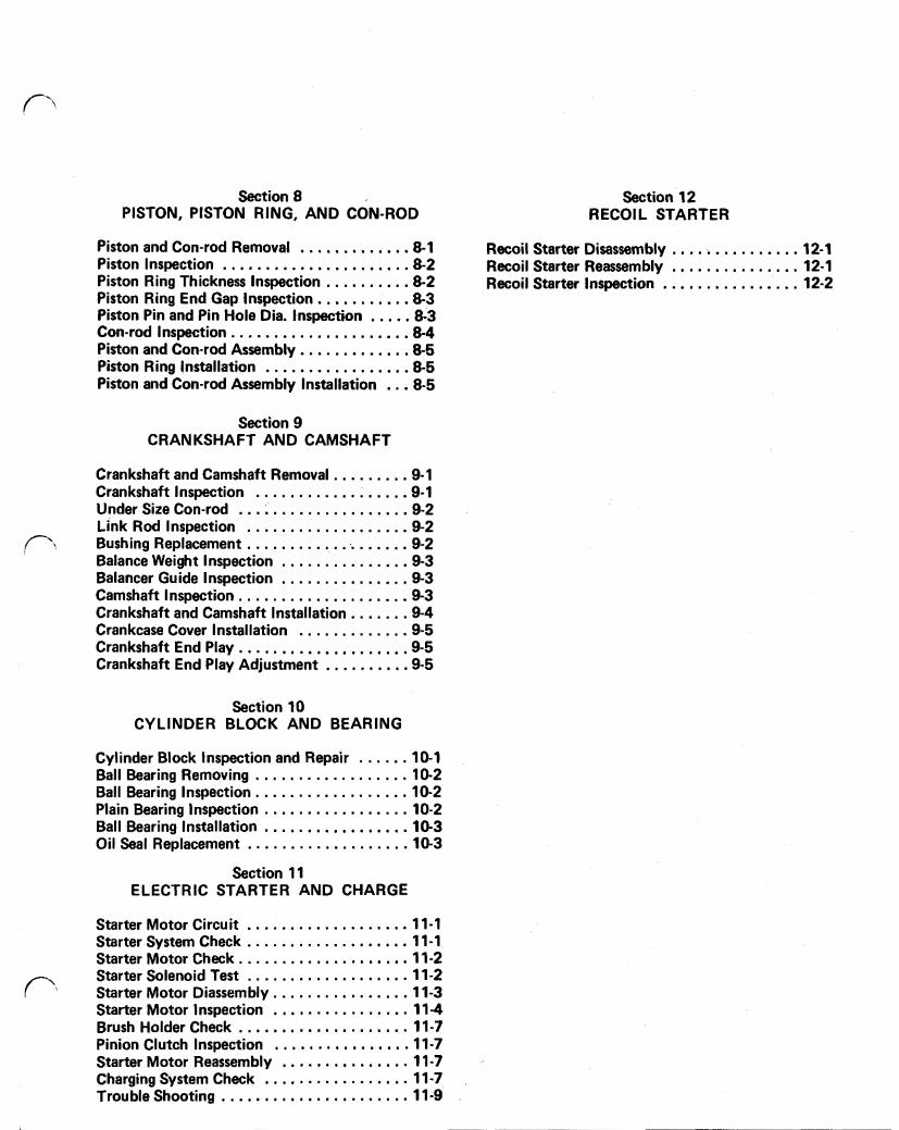
SECTION 8 - PISTON, PISTON RING, AND CON-ROD PISTON AND CON-ROD REMOVAL PISTON INSPECTION PISTON RING THICKNESS INSPECTION PISTON RING END GAP INSPECTION PISTON PIN AND PIN HOLE DIA. INSPECTION CON-ROD INSPECTION PISTON AND CON-ROD ASSEMBLY PISTON RING INSTALLATION PISTON AND CON-ROD ASSY INSTALLATION
KAWASAKI FB460V ENGINE MANUAL
Table of Contents – Page 3 of 3
SECTION 9--CRANKSHAFT AND CAMSHAFT CRANKSHAFT AND CAMSHAFT REMOVAL CRANKSHAFT INSPECTION UNDER-SIZE CON-ROD LINK ROD INSPECTION BUSHING REPLACEMENT BALANCE WEIGHT INSPECTION BALANCER GUIDE INSPECTION CAMSHAFT INSPECTION CRANKSHAFT AND CAMSHAFT INSTALLATION CRANKCASE COVER INSTALLATION CRANKSHAFT END PLAY CRANKSHAFT END PLAY ADJUSTMENT
SECTION 10--CYLINDER BLOCK AND BEARING CYLINDER BLOCK INSPECTION AND REPAIR BALL BEARING REMOVING BALL BEARING INSPECTION PLAIN BEARING INSPECTION BALL BEARING INSTALLATION OIL SEAL REPLACEMENT (PTO SIDE)
SECTION 11 - ELECTRIC STARTER AND CHARGE STARTER MOTOR CIRCUIT STARTER SYSTEM CHECK STARTER MOTOR CHECK STARTER SOLENOID TEST STARTER MOTOR DISASSEMBLY STARTER MOTOR INSPECTION BRUSH HOLDER CHECK PINION CLUTCH INSPECTION STARTER MOTOR REASSEMBLY CHARGING SYSTEM CHECK TROUBLESHOOTING
SECTION 12 - RECOIL STARTER RECOIL STARTER DISASSEMBLY RECOIL STARTER REASSEMBLY RECOIL STARTER INSPECTION
4-stroke air-cooled gasoline engine
FOREWORD
This manual is designed for use by trained mecha- nics in a properly equipped shop. In order to perform the work efficiently and to avoid costly mistakes, read the text, thorough- ly familiarize yourself with the procedures before starting work, and then do the work carefully in a clean area. Whenever special tools or equip- ment are specified, do not use makeshift tools or equipment. Precision measurements can only be made if the proper instruments are used, and the use of substitute tools may adversely affect safe operation.
Whenever you see these WARNING and CAUTION symbols, heed their instructions! Always follow safe operating and maintenance practices.
WARNING: This warning symbol identifies special instructions or procedures which, if not correctly followed, could result in fire, personal injury, or loss of life.
CAUTION: This identifies special instructions or procedures which, if not strictly observed, could result in equipment damage or destruction.
NOTE: Indicates message or points of partic- ular interest for more efficient and convenient operation.
The term "Replace" and some abbreviations are used as follows:
Replace - usually means replace with a new part.
MIN = Minimum MAX = Maximum Ass'y = Assembly STD = Standard I Ilust. = I llustration Spec. = Specification(s) PTO = Power take off Approx. = Approximately (Approximate) Carb. = Carburetor Con-rod = Connecting rod Cyl. = Cylinder
All rights reserved. No part of this publication may be reproduced, stored in a retrieval system, or transmitted in any form or by any means, electronic mechanical photocopying, recording or otherwise, without the prior written permission of Engine Division/Kawasaki Heavy Industries, Ltd. No liability can be accepted for any inac- curacies or omissions in this publication, although every possible care has been taken to make it as complete and accurate as possible. All procedures and specifications subject to change without prior notice or obligation. Illustrations in this publi- cation are intended for reference use only and may not depict actual model component parts.
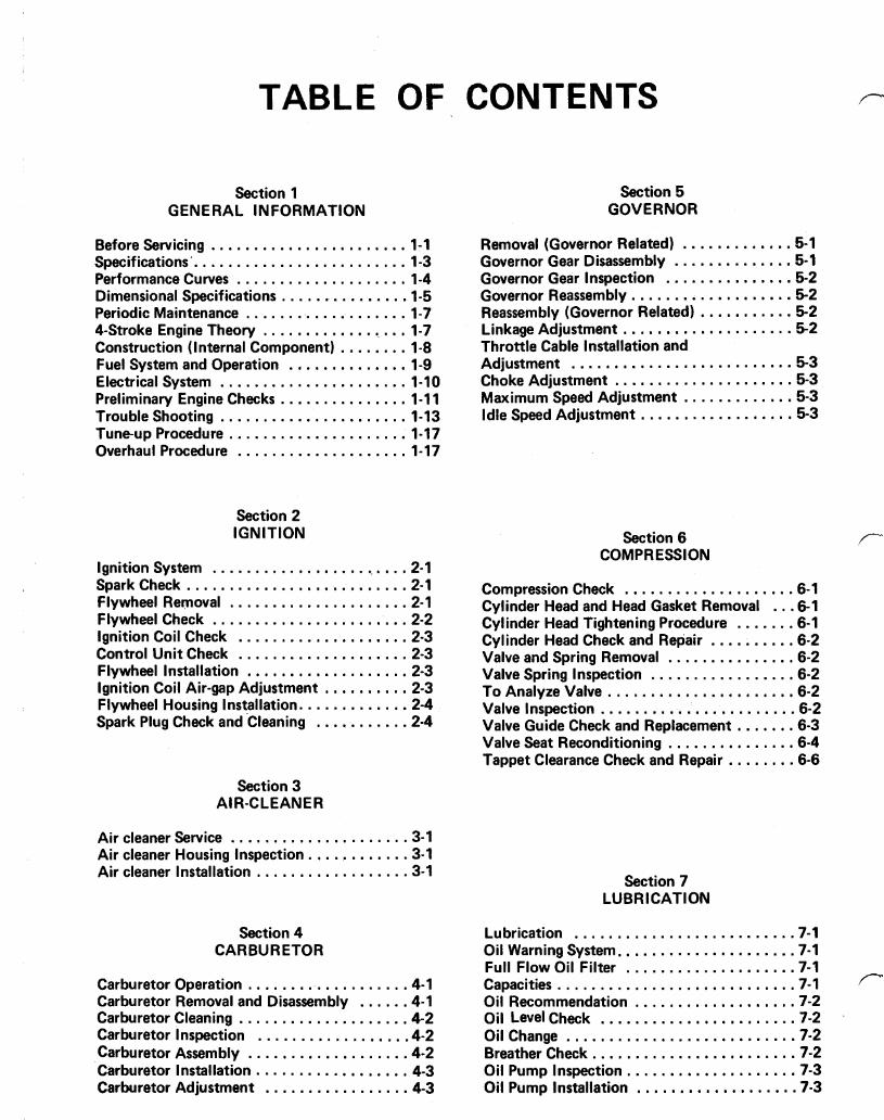
TABLE OF CONTENTS /-
Section 1 GENERAL INFORMATION
Before Servicing ....................... 1-1
Performance Curves .................... 1-4 Dimensional Specifications . . . . . ......... 1-5 Periodic Maintenance ................... 1-7 4-Stroke Engine Theory .................. 1-7 Construction (Internal Component) . ....... 1-8 Fuel System and Operation .............. 1-9 Electrical System ...................... 1-10 Preliminary Engine Checks ............... 1-11 Trouble Shooting ...................... 1-13 Tune-up Procedure ..................... 1-17 Overhaul Procedure .................... 1-17
Specifications. ......................... 1-3
Section 2 IGNITION
Ignition System ........................ 2-1 Spark Check .......................... 2.1 Flywheel Removal ..................... 2.1 Flywheel Check ....................... 2.2 Ignition Coil Check .................... 2-3 Control Unit Check .................... 2-3 Flywheel Installation ................... 2-3 Ignition Coil Air-gap Adjustment . . . . . . . . . . 2-3 Flywheel Housing Installation ............. 2-4 Spark Plug Check and Cleaning ........... 2.4
Section 3 AlR-CLEANER
Air cleaner Service ..................... 3.1 Air cleaner Housing Inspection ............ 3.1 Air cleaner Installation . . . . . . . . . . . . . . . . . . 3.1
Section 4 CARBURETOR
Carburetor Operation . . . . . . . . . . . . . . . . . . . 4.1 Carburetor Removal and Disassembly . . . . . . 4.1 Carburetor Cleaning .................... 4-2 Carburetor Inspection . . . . . . . . . . . . . . . . . . 4.2 Carburetor Assembly . . . . . . . . . . . . . . . . . . . 4.2 Carburetor Installation .................. 4-3 Carburetor Adjustment ................. 4-3
Section 5 GOVERNOR
Removal (Governor Related) ............. 5-1 Governor Gear Disassembly .............. 5-1 Governor Gear Inspection ............... 5-2 Governor Reassembly ................... 5-2 Reassembly (Governor Related) ........... 5-2 Linkage Adjustment .................... 5-2
Adjustment .......................... 5-3 Choke Adjustment ..................... 5-3 Maximum Speed Adjustment ............. 5-3 Idle Speed Adjustment .................. 5-3
Throttle Cable Installation and
Section 6 COMPRESSION
Compression Check .................... 6-1 Cylinder Head and Head Gasket Removal . . . 6-1 Cylinder Head Tightening Procedure ....... 6-1 Cylinder Head Check and Repair . ......... 6-2 Valve and Spring Removal . .............. 6-2 Valve Spring Inspection . . . . . . . . . . . . . . . . . 6-2 To Analyze Valve ...................... 6-2 Valve Inspection ....................... 6-2 Valve Guide Check and Replacement . . . . . . . 6-3 Valve Seat Reconditioning . . . . . . . . . . . . . . . 6-4 Tappet Clearance Check and Repair . . . . . . . . 6-6
Section 7 LUBRICATION
Lubrication .......................... 7-1 Oil Warning System ..................... 7-1 Full Flow Oil Filter .................... 7-1 Capacities ............................ 7-1 Oil Recommendation . . . . . . . . . . . . . . . . . . . 7-2 Oil Level Check ....................... 7-2 Oil Change ........................... 7-2 Breather Check ........................ 7-2 Oil Pump Inspection .................... 7-3 Oil Pump Installation ................... 7-3
Section 8 PISTON. PISTON RING. AND CON-ROD
Section 12 RECOIL STARTER
Piston and Con-rod Removal ............. 8-1 Recoil Starter Disassembly ............... 12-1 Piston Inspection ...................... 8.2 Recoil Starter Reassembly ............... 12-1 Piston Ring Thickness Inspection .......... 8-2 Recoil Starter Inspection ................ 12-2 Piston Ring End Gap Inspection ........... 8-3 Piston Pin and Pin Hole Dia . Inspection ..... 8-3 Con-rod Inspection ..................... 8-4 Piston and Con-rod Assembly ............. 8-5 Piston Ring Installation ................. 8-5 Piston and Con-rod Assembly Installation ... 8-5
Section 9 CRANKSHAFT AND CAMSHAFT
Crankshaft and Camshaft Removal ......... 9-1 Crankshaft Inspection .................. 9-1 Under Size Con-rod .................... 9-2 Link Rod Inspection ................... 9-2 Bushing Replacement ................... 9-2 Balance Weight Inspection ............... 9-3 Balancer Guide Inspection ............... 9-3 Camshaft Inspection .................... 9-3 Crankshaft and Camshaft Installation ....... 9-4 Crankcase Cover Installation ............. 9-5 Crankshaft End Play .................... 9-5 Crankshaft End Play Adjustment .......... 9-5
Section 10 CYLINDER BLOCK AND BEARING
Cylinder Block Inspection and Repair ...... 10-1 Ball Bearing Removing .................. 10-2 Ball Bearing Inspection .................. 10-2 Plain Bearing Inspection ................. 10-2 Ball Bearing Installation ................. 10-3 Oil Seal Replacement ................... 10-3
Section 11 ELECTRIC STARTER AND CHARGE
Starter Motor Circuit ................... 11-1 Starter System Check ................... 11-1 Starter Motor Check .................... 11-2 Starter Solenoid Test . .................. 11-2
Starter Motor Inspection ................ 11-4 Brush Holder Check .................... 11-7 Pinion Clutch Inspection ................ 11-7 Starter Motor Reassembly ............... 11-7 Charging System Check ................. 11-7 Trouble Shooting ...................... 11-9
Starter Motor Diassembly ................ 11-3
1-1 GENERAL INFORMATION
Section 1
GENERAL INFORMATION
BEFORE SERVICING
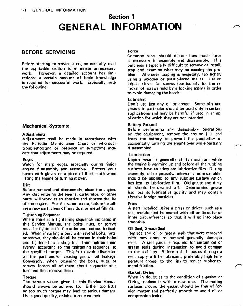
Before starting to service a engine carefully read the applicable section to eliminate unnecessary work. However, a detailed account has limi- tations; a certain amount of basic knowledge is required for successful work. Especially note the following:
Mechanical Systems: Adjustments Adjustments shall be made in accordance with the Periodic Maintenance Chart or whenever troubleshooting or presence of symptoms indi- cate that adjustments may be required.
Edges Watch for sharp edges, especially during major engine disassembly and assembly. Protect your hands with gloves or a piece of thick cloth when lifting the engine or turning it over.
Dirt Before removal and disassembly, clean the engine. Any dirt entering the engine, carburetor, or other parts, will work as an abrasive and shorten the life of the engine. For the same reason, before install- ing a new part, clean off any dust or metal fillings.
Tightening Sequence Where there is a tightening sequence indicated in this Service Manual, 'the bolts, nuts, or screws must be tightened in the order and method indicat- ed. When installing a part with several bolts, nuts, or screws, they should all be started in their holes and tightened to a shug fit. Then tighten them evenly, according to the tightening sequence, to the specified torque. This is to avoid distortion of the part and/or causing gas or oil leakage. Conversely, when loosening the bolts, nuts, or screws, loosen all of them about a quarter of a turn and then remove them. Torque The torque values given in this Service Manual should always be adhered to. Either too little or too much torque may lead to serious damage. Use a good quality, reliable torque wrench.
Force Common sense should dictate how much force is necessary in assembly and disassembly. If a part seems especially difficult to remove or install, stop and examine what may be causing the pro- blem. Whenever tapping is necessary, tap lightly using a wooden or plastic-faced mallet. Use an impact driver for screws (particularly for the re- moval of screws held by a lacking agent) in order to avoid damaging the heads.
Lubricant Don't use just any oil or grease. Some oils and greases in particular should be used only in certain applications and may be harmful i f used in an ap- plication for which they are not intended.
Battery Ground Before performing any disassembly operations on the equipment, remove the ground (-) lead from the battery to prevent the possibility of accidentally turning the engine over while partially disassembled.
Lubrication Engine wear is generally a t i t s maximum while the engine is warming up and before all the rubbing surfaces have an adequate lubricative film. During assembly, oil or grease (whichever is more suitable) should be applied to any rubbing surfave which has lost i t s lubricative film. Old grease and dirty oil should be cleaned off. Deteriorated grease has lost i t s lubricative quality and may contain abrasive foreign particles. Press A part installed using a press or driver, such as a seal, should first be coated with oil on i t s outer or inner circumference so that it will go into place smoothly.
Oil Seal, Grease Seal Replace any oil or grease seals that were removed with new ones, as removal generally damages seals. A seal guide is required for certain oil or grease seals during installation to avoid damage to the seal lips. Before a shaft passes through a seal, apply a l i t t le lubricant, preferably high tem- perature grease, to the lips to reduce rubber-to- metal friction.
Gasket, O-ring When in doubt as to the condition of a gasket or O-ring, replace it. with a new one. The mating surfaces around the gasket should be free of for- eign matter and perfectly smooth to avoid oil or compression leaks.
GENERAL INFORMATION 1-2
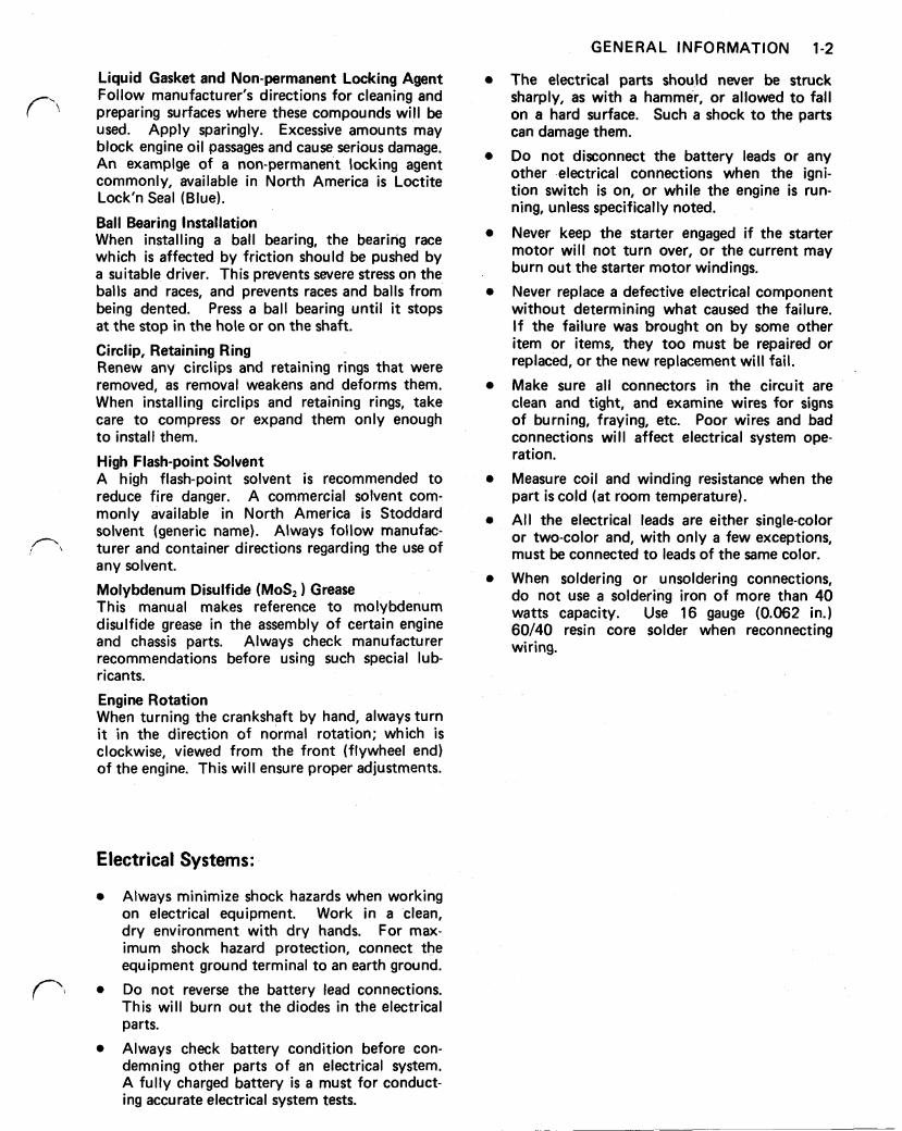
Liquid Gasket and Non-permanent Locking Agent Follow manufacturer's directions for cleaning and preparing surfaces where these compounds will be used. Apply sparingly. Excessive amounts may block engine oil passages and cause serious damage. An example of a non-permanent locking agent commonly, available in North America is Loctite Lock'n Seal (Blue).
Ball Bearing Installation When installing a ball bearing, the bearing race which is affected by friction should be pushed by a suitable driver. This prevents severe stress on the balls and races, and prevents races and balls from being dented. Press a ball bearing until it stops a t the stop in the hole or on the shaft.
Circlip, Retaining Ring Renew any circlips and retaining rings that were removed, as removal weakens and deforms them. When installing circlips and retaining rings, take care to compress or expand them only enough to install them.
High Flash-point Solvent A high flash-point solvent is recommended to reduce fire danger. A commercial solvent com- monly available in North America is Stoddard solvent (generic name). Always follow manufac- turer and container directions regarding the use of any solvent.
Molybdenum Disulfide ) Grease This manual makes reference to molybdenum disulfide grease in the assembly of certain engine and chassis parts. Always check manufacturer recommendations before using such special lub- ricants.
Engine Rotation When turning the crankshaft by hand, always turn it in the direction of normal rotation; which is clockwise, viewed from the front (flywheel end) of the engine. This will ensure proper adjustments.
Electrical Systems:
Always minimize shock hazards when working on electrical equipment. Work in a clean, dry environment with dry hands. For max- imum shock hazard protection, connect the equipment ground terminal to an earth ground.
Do not reverse the battery lead connections. This will burn out the diodes in the electrical parts.
Always check battery condition before con- demning other parts of an electrical system. A fully charged battery is a must for conduct- ing accurate electrical system tests.
The electrical parts should never be struck sharply, as with a hammer, or allowed to fall on a hard surface. Such a shock to the parts can damage them.
Do not disconnect the battery leads or any other electrical connections when the igni- tion switch is on, or while the engine is run- ning, unless specifically noted.
Never keep the starter engaged if the starter motor will not turn over, or the current may burn out the starter motor windings.
Never replace a defective electrical component without determining what caused the failure. I f the failure was brought on by some other item or items, they too must be repaired or replaced, or the new replacement will fail.
Make sure all connectors in the circuit are clean and tight, and examine wires for signs of burning, fraying, etc. Poor wires and bad connections will affect electrical system ope- ration.
Measure coil and winding resistance when the part is cold (at room temperature).
All the electrical leads are either single-color or two-color and, with only a few exceptions, must be connected to leads of the same color.
When soldering or unsoldering connections, do not use a soldering iron of more than 40 watts capacity. Use 16 gauge (0.062 in.) 60/40 resin core solder when reconnecting wiring.
1-3 GENERAL INFORMATION
SPECI FlCATlONS
ENGINE MODEL ENGINE TYPE NUMBER OF CYLINDER PISTON DISPLACEMENT BORE x STROKE COMPRESSION RATIO
MAX. OUTPUT MAX. TORQUE MIN. SPECIFIC FUEL CONSUMPTION RATIO
DIRECTION OF ROTATION FAST IDLE SPEED SETTING SLOW IDLE SPEED SETTING
LUBRICATION BALANCING THROTTLE CONTROL CHOKE CONTROL STARTER CARBURETOR IGNITION CHARGING COIL RFI GOVERNOR OIL FILL AND DIP STICK OIL DRAIN COOLING AIR INLET COOLING SHROUDS AIR CLEANER
LUBRICANT
FUEL
DIMENSION (H x W x L)
NET WEIGHT
OPTIONAL PARTS
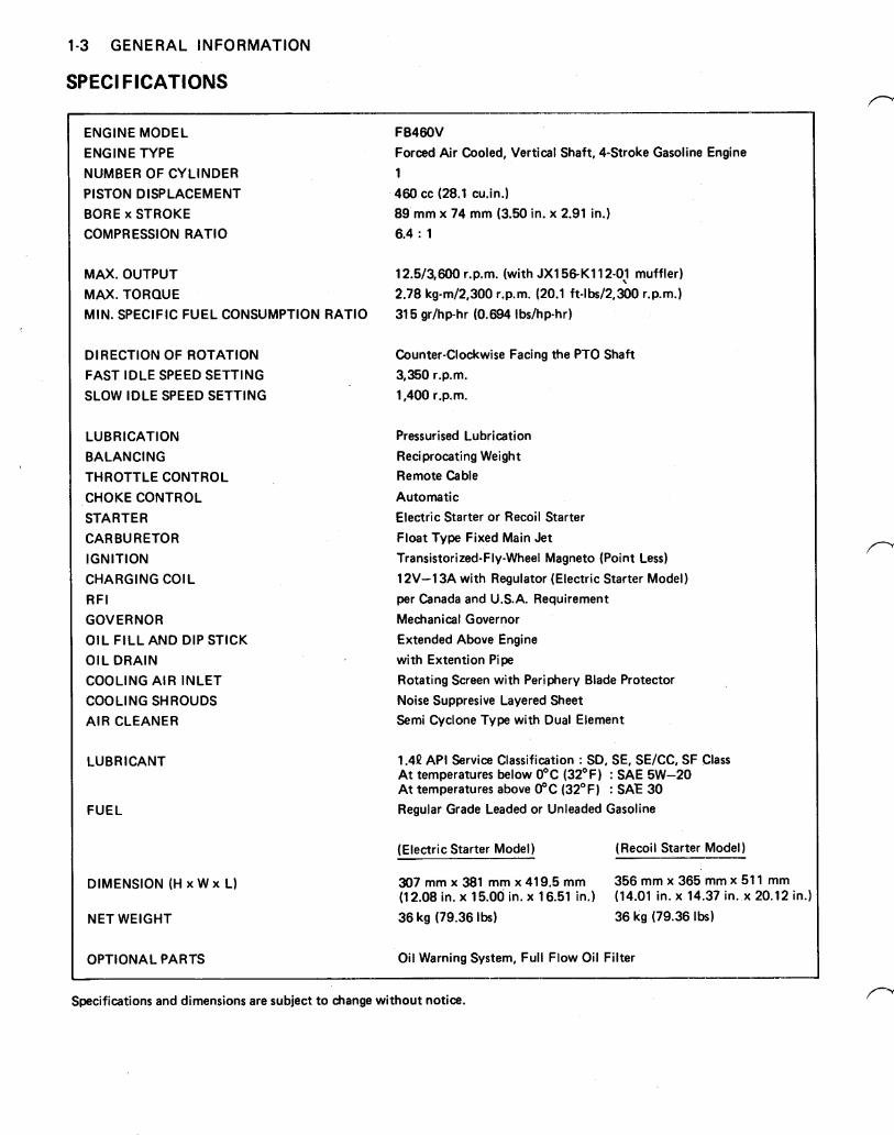
FB460V Forced Air Cooled, Vertical Shaft, 4-Stroke Gasoline Engine 1 460 cc (28.1 cu.in.) 89 mm x 74 mm (3.50 in. x 2.91 in.) 6.4 : 1
12.5/3,600 r.p.m. (with JX156-K112-01 muffler) 2.78 kg-m/2,300 r.p.m. (20.1 ft-lbs/2,300 r.p.m.) 315 gr/hp-hr (0.694 Ibs/hp-hr)
Counter-Clockwise Facing the PTO Shaft 3,350 r.p.m. 1,400 r.p.m.
Pressurised Lubrication Reciprocating Weight Remote Cable
Automatic Electric Starter or Recoil Starter Float Type Fixed Main Jet Transistorized-Fly-Wheel Magneto (Point Less) 12V-13A with Regulator (Electric Starter Model per Canada and U.S.A. Requirement Mechanical Governor Extended Above Engine with Extention Pipe Rotating Screen with Periphery Blade Protector Noise Suppresive Layered Sheet Semi Cyclone Type with Dual Element
API Service Classification : SD, SE, SE/CC, SF Class At temperatures below 0°C (32°F) : SAE 5W-20 At temperatures above 0°C (32°F) : SAE 30 Regular Grade Leaded or Unleaded Gasoline
(Electric Starter Model) (Recoil Starter Model)
307 mm x 381 mm x 419.5 mm 356 mm x 365 mm x 511 mm (12.08 in. x 15.00 in. x 16.51 in.) (14.01 in. x 14.37 in. x 20.12 in. 36 kg (79.36 Ibs) 36 kg (79.36 Ibs)
Oil Warning System, Full Flow Oil Filter
Specifications and dimensions are subject to change without notice.
GENERAL INFORMATION 1-4
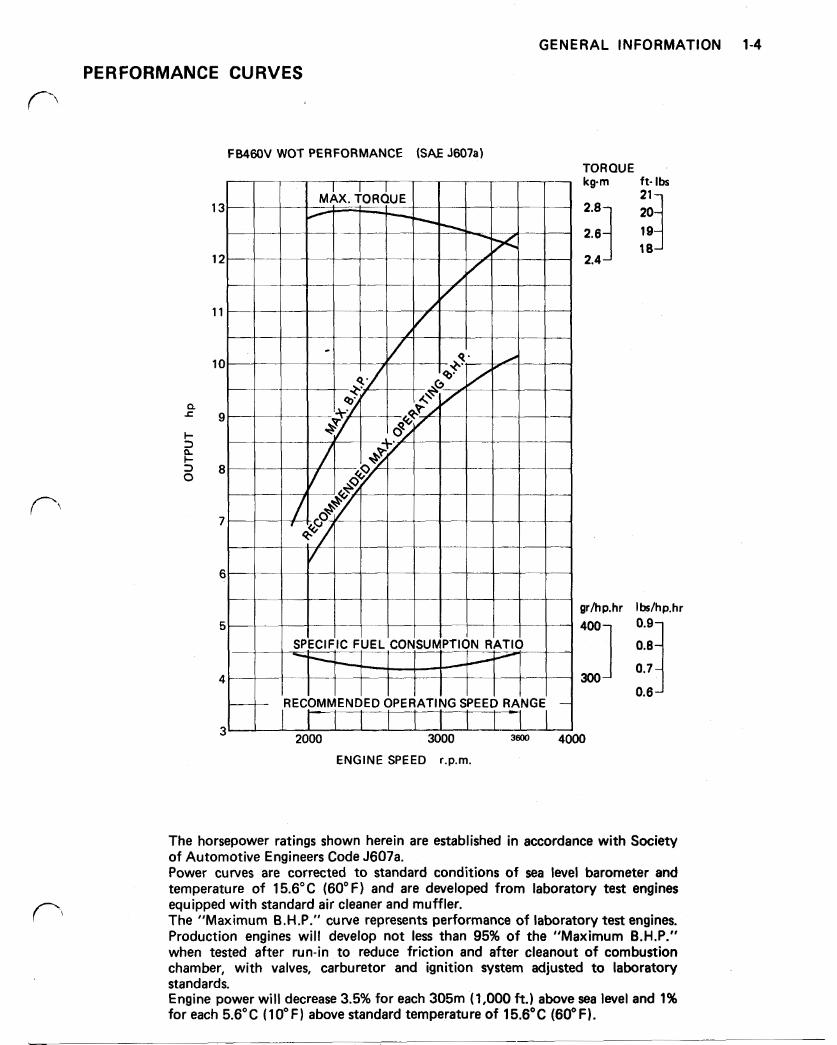
PERFORMANCE CURVES
FB46OV WOT PERFORMANCE (SAE J607a) TORQUE kgm ft- Ibs
2.6
2.4 18
gr/hp.hr Ibs/hp.hr
300
2000 3000 3600 4000
ENGINE SPEED r.p.m.
The horsepower ratings shown herein are established in accordance with Society of Automotive Engineers Code J607a. Power curves are corrected to standard conditions of sea level barometer and temperature of 15.6°C (60" F) and are developed from laboratory test engines equipped with standard air cleaner and muffler. The "Maximum B.H.P." curve represents performance of laboratory test engines. Production engines will develop not less than 95% of the "Maximum B.H.P." when tested after run-in to reduce friction and after cleanout of combustion chamber, with valves, carburetor and ignition system adjusted to laboratory standards. Engine power will decrease 3.5% for each 305m (1,000 ft.) above sea level and 1% for each 5.6°C (10°F) above standard temperature of 15.6°C (60°F).
1-5 GENERAL INFORMATION
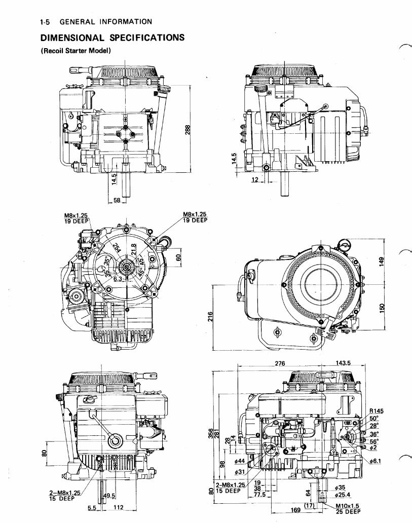
DIMENSIONAL SPECIFICATIONS (Recoil Starter Model)
276 143.5 I
GENERAL INFORMATION 1-6
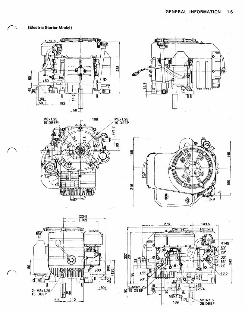
(Electric Starter Model)
1-7 GENERAL INFORMATION
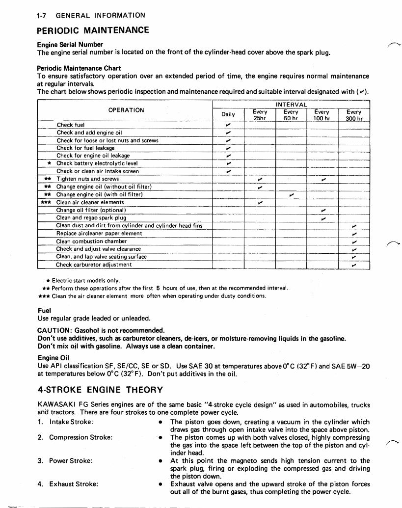
PERIODIC MAINTENANCE Engine Serial Number The engine serial number is located on the front of the cylinder-head cover above the spark plug.
Periodic Maintenance Chart To ensure satisfactory operation over an extended period of time, the engine requires normal maintenance a t regular intervals. The chart below shows periodic inspection and maintenance required and suitable interval designated with
Electric start models only. Perform these operations after the first 5 hours of use, then a t the recommended interval. Clean the air cleaner element more often when operating under dusty conditions.
Fuel Use regular grade leaded or unleaded.
CAUTION: Gasohol is not recommended. Don't use additives, such as carburetor cleaners, de-icers, or moisture-removing liquids in the gasoline. Don't mix oil with gasoline. Always use a clean container.
Engine Oil Use API classification SF, SE/CC, SE or SD. Use SAE 30 at temperatures above 0°C (32°F) and SAE 5W-20 at temperatures below 0°C (32°F). Don't put additives in the oil.
4-STROKE ENGINE THEORY
KAWASAKI FG Series engines are of the same basic "4-stroke cycle design" as used in automobiles, trucks and tractors. There are four strokes to one complete power cycle. 1.
2.
3.
4.
Intake Stroke:
Compression Stroke:
Power Stroke:
Exhaust Stroke:
The piston goes down, creating a vacuum in the cylinder which draws gas through open intake valve into the space above piston. The piston comes up with both valves closed, highly compressing the gas into the space left between the top of the piston and cyl- inder head. At this point the magneto sends high tension current to the spark plug, firing or exploding the compressed gas and driving the piston down. Exhaust valve opens and the upward stroke of the piston forces out all of the burnt gases, thus completing the power cycle.
GENERAL INFORMATION 1-8
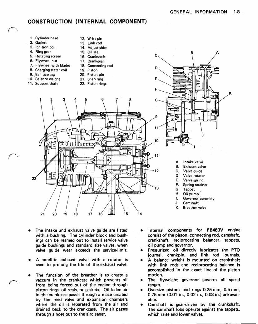
CONSTRUCTION (INTERNAL COMPONENT)
1. Cylinder head 2. Gasket 3. Ignition coil 4. Ring gear 5. Rotating screen 6. Flywheel nut 7. Flywheel with blades 8. Charging stater coil 9. Ball bearing
10. Balance weight 1 1. Support shaft
12. Wrist pin 13. Link rod 14. Adjust shim 15. Oil seal 16. Crankshaft 17. Crankgear 18. Connecting rod 19. Piston 20. Piston pin 21. Snap ring 22. Piston rings
The intake and exhaust valve guide are fitted with a bushing. The cylinder block and bush- ings can be reamed out to install service valve guide bushings and standard size valves, when valve guide wear exceeds the service-limit.
A satellite exhaust valve with a rotator is used to prolong the life of the exhaust valve.
The function of the breather is to create a vaccum in the crankcase which prevents oil from being forced out of the engine through piston rings, oil seals, or gaskets. Oil laden air in the crankcase passes through a maze created by the reed valve and expansion chambers where the oil is separated from the air and drained back to the crankcase. The air passes through a hose out to the aircleaner.
11
A. Intake valve B. Exhaust valve
D. Valve rotater E. Valve spring F. Spring retainer
H. Oil pump I. Governor assembly J. Camshaft K. Breather valve
12 C. Valve guide
13 G . Tappet
\ 14
Internal components for FB460V engine consist of the piston, connecting rod, camshaft, crankshaft, reciprocating balancer, tappets, oil pump and governor. Pressurized oil directly lubricates the PTO journal, crankpin, and link rod journals. A balance weight is mounted on crankshaft with link rods and reciprocating balance is accomplished in the exact line of the piston motion. The flyweight governor governs all speed ranges. Oversize pistons and rings 0.25 mm, 0.5 mm, 0.75 mm (0.01 in., 0.02 in., 0.03 in.) are avail- able. Camshaft is gear-driven by the crankshaft. The camshaft lobs operate against the tappets, which raise and lower valves.
1-9 GENERAL INFORMATION
FUEL SYSTEM AND OPERATION n
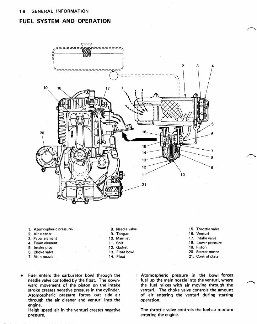
1. Atomospheric pressure 8. Needle valve 15. Throttle valve 2. Air cleaner 9. Tongue 16. Venturi 3. Paper element 10. Main jet 17. Intake valve 4. Foam element 11. Bolt 18. Lower pressure 5. Intake pipe 12. Gasket 19. Piston 6. Choke valve 13. Float bowl 20. Starter motor 7. Main nozzle 14. Float 21. Control plate
Fuel enters the carburetor bowl through the needle valve contolled by the float. The down- ward movement of the piston on the intake stroke creates negative pressure in the cylinder. Atomospheric pressure forces out side air through the air cleaner and venturi into the engine. Heigh speed air in the venturi creates negative pressure.
Atomospheric pressure in the bowl forces fuel up the main nozzle into the venturi, where the fuel mixes with air moving through the venturi. The choke valve controls the amount of air entering the venturi during starting operation.
The throttle valve controls the fuel-air mixture entering the engine.
n
n
GENERAL INFORMATION 1-10
ELECTRICAL SYSTEM
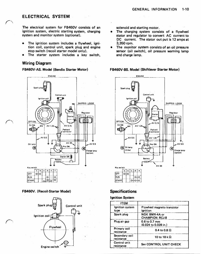
The electrical system for FB460V consists of an ignition system, electric starting system, charging system and monitor system (optional).
The ignition system includes a flywheel, igni- tion coil, control unit, spark plug and engine stop switch (recoil starter model only). The starter system includes a key switch,
Wiring Diagram FB46OV-AS. Model (Bendix Starter Motor)
ENGINE
Key switch
FB460V. (Recoil-Starter Model)
solenoid and starting motor. The charging system consists of a flywheel stator and regulator to convert AC current to DC current. The stator out put is 12 amps a t 3,350 rpm. The monitor system consists of an oil pressure sensor (oil switch), oil pressure warning lamp and charge lamp.
FB46OV-BS. Model (Shiftlever Starter Motor)
ENGINE
Spark plug
I Control unit
OFF
RUN
START
Specifications Ignition System
~-
ignition NGK BMR4A or CHAMPION RCJ-8 0.6 to 0.7 mm
Control unit I resistance See CONTROL UNIT CHECK
1-1 1 GENERAL INFORMATION
Electric Starter System (Bendix-type) I ITEM 1
Battery rating
12 V - 0.8 KW Starter-rating current
One tenth of battery capacity Max charging 12 V/35 A.H. or more
Brush length 12 mm (0.47 in.) (MINI I Commutator groove depth
0.2 mm (0.008 in.) (MINI
diameter 32 mm (1.26 in.) (MINI Commutator
12 V, 7000 rpm (MINI 60A (MAX) Current draw Run-out
0.3 mm (0.012 in.) (MAX) Commutator
Electric Starter System (Shiftlever-type) I
Battery rating
12 V - 0.75 KW Starter-rating current
One-tenth of battery capacity Max charging 12 A.H. / 35 A.H. or more
Brush length 6 mm (0.24 in.) (MIN) I Commutator 0.2 rnm (0.008 in.) (MIN) I groove depth Commutator 27 mm (1.10 in.) (MAX) diameter Commutator 0.4 mm (0.016 in.) (MAX) run-out I Current draw 11.5 V, 6000 rpm (MINI test 50A (MAX)
Charging System I ITEM I I
Stator output
12V system, constant voltage, Regulator-type 34.5 V / 3350 rpm (MIN) No-load voltage Approx. 12 amps-0 rpm
regulator Regulator resistance
See Regulator Inspection A
Monitor System
PRELIMINARY ENGINE CHECKS
A complete diagnosis of engine malfunctions appears in this section. However, the majority of engine problems is normally due to ignition or fuel system diffi- culties.
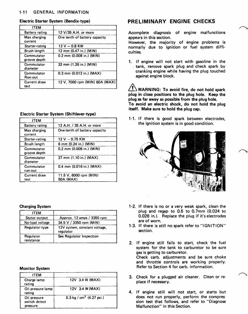
1. I f engine will not start with gasoline in the tank, remove spark plug and check spark by cranking engine while having the plug touched against engine block.
WARNING: To avoid fire, do not hold spark plug in close positions to the plug hole. Keep the plug as far away as possible from the plug hole. To avoid an electric shock, do not hold the plug itself. Make sure to hold the plug cap.
1-1.
1-2.
1-3.
2.
3.
4.
If there is good spark between electrodes, the ignition system is in good condition.
I f there is no or a very weak spark, clean the plug and regap to 0.6 to 0.7mm (0.024 to 0.028 in.). Replace the plug if it's electrodes are of worn. I f there is still no spark refer to "IGNITION" section.
I f engine still fails to start, check the fuel system for the tank to carburetor to be sure gas is getting to carburetor. Check carb. adjustments and be sure choke and throttle controls are working properly. Refer to Section 4 for carb. information.
Check for a plugged air cleaner. Clean or re- place if necessary.
I f engine still will not start, or starts but does not run properly, perform the compres- sion test that follows, and refer to "Diagnose Malfunction" in this Section.
5. Test compression when engine loses power or runs erratically and fuel and ignition systems adjustments do not correct the problem.
CAUTION: Disconnect spark plug cap to prevent engine from starting during compression test.
6. Crank engine with electric or recoil starter and check the compression force.
7. If compression is low, it is usually the result of one or more of following:
Leaking cyl. head gasket. Warped cyl. head. Worn piston rings. Worn cyl. bore. Damaged piston. Burned or warped valves. Improper valve clearance. Broken valve springs.
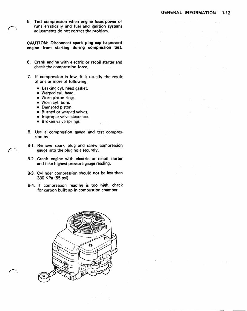
8. Use a compression gauge and test compres- sion by:
8-1. Remove spark plug and screw compression gauge into the plug hole securely.
8-2. Crank engine with electric or recoil starter and take highest pressure gauge reading.
8-3. Cylinder compression should not be less than
8-4. If compression reading is too high, check
380 KPa (55 psi).
for carbon built up in combustion chamber.
GENERAL INFORMATION 1-12
1-13 GENERAL INFORMATION
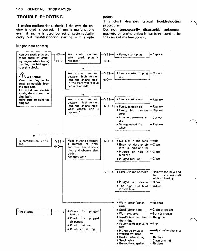
TROUBLE SHOOTING points. This chart describes typical troubleshooting
I f engine malfunctions, check i f the way the en- procedures. gine is used is correct. If engine malfunctions Do not unnecessarily disassemble carburetor, even i f engine is used correctly, systematically magneto or engine unless it has been found to be carry out troubleshooting starting with simple the cause of malfunctioning.
[Engine hard to start]
I Remove spark plug and check spark by crank- ing engine while having the plug touched again- s t engine block.
WARNING: Keep the plug as far away as possible from the plug hole. To avoid an electric shock, do not hold the plug itself. ,Make sure to hold the plug cap.
between high tension lead and engine block in the state where plug
Are sparks produced between high tension lead and engine block when control unit is replaced?
Make starting attempts number of times
and then remove spark plug and observe elec-
Are they wet? [odes.
gap
wheel Demagnetized fly- Replace
NO-
Y ES-,
into fuel pipe or filter
tank cap Plugged fuel line Clean
turn the crankshaft without loading
in float bowl
Worn piston/piston rings t Replace
Check carb. fuel line.
air passage. Check for plugged
Check float level.
Stuck piston rings Clean or replace Worn cyl. bore Bore or replace
tightening
seat Plunge-up by valve Adjust valve clearance Warped cyl. head Broken valve spring Replace
Replace Stuck valve Clean or grind
GENERAL INFORMATION 1-14
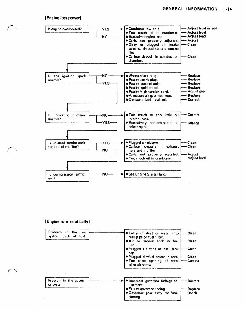
[Engine loss power]
Is the ignition spark NO- normal?
Is lubricating condition NO- normal?
Is unusual smoke emit- YES ted out of muffler?
Adjust level or add
Excessive engine load. Adjust load
screens, shrouding and engine fins.
chamber.
Wrong spark plug. Replace Faulty spark plug. Replace Faulty control unit. Replace Faulty ignition coil Replace Faulty high tension cord. Adjust gap Armature air gap incorrect. Replace Demagnetized flywheel. Correct
in crankcase.
bricating oil.
Plugged air cleaner. Clean @Carbon deposit in
not properly Too much oil in crankcase. Adjust level
hole and muffler.
-I_--
Is compression suffici- ent? Hard.
[Engine runs erratically]
fuel pipe or fuel filter.
I Problem in the govern- or system justment.
Faulty governor spring. Replace
tioning.
1-15 GENERAL INFORMATION
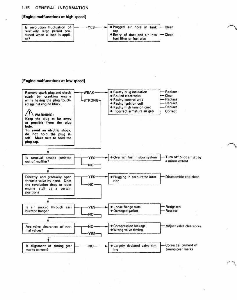
[Engine malfunctions at high speed]
Is revolution fluctuation of relatively large period pro- duced when a load is appli-
fuel filter or fuel pipe
[Engine malfunctions a t low speed]
Remove spark plug and check spark by cranking engine while having the plug touch- ed against engine block.
WARNING: Keep the plug as far away as possible from the plug hole. To avoid an electric shock, do not hold the plug it- self. Make sure to hold the plug cap.
J
Faulty plug insulation Replace Fouled electrodes Clean Faulty control unit Replace Faulty ignition coil Replace Faulty high tension cord Replace Incorrect armature air gap Correct
t Is unusual smoke emitted out of muffler? a minor extent
Overrich fuel in slow system Turn off pilot air je t by
NO
Directly and gradually open Disassemble and clean throttle valve by hand. Does the revolution drop or does engine stall a t a certain position?
Is air sucked through car- Retighten buretor flange? Damaged gasket Replace
t Are valve clearances of nor- Adjust valve clearances mal values? Wrong valve timing
YES
t Is alignment of timing gear
timing gear marks i ng marks correct? alignment of Largely deviated valve tim-
GENERAL INFORMATION 1-16
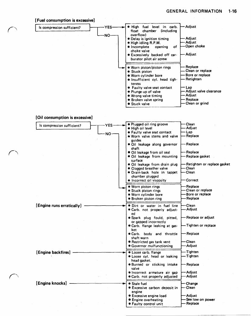
[Fuel consumption is excessive]
compression sufficient? Is r
High fuel level in carb. -Adjust float chamber (including overflow) Delay is ignition timing High idling R.P.M.
-Adjust
choke Incomplete opening of -Adjust
Excessively backed off car- choke valve
burator pilot air screw
Replace Stuck piston Worn cylinder bore
-Clean or replace
insufficient cyl. head tigh- -Bore or replace
Faulty valve seat contact Plunge-up of valve -Adjust valve clearance Wrong valve timing -Adjust Broken valve spring
-Clean or grind Stuck valve -Replace
teness
[Oil consumption is excessive]
YES-
[Engine runs erratically]
[Engine backfires]
[Engine knocks]
Plugged oil ring groove
Worn valve stems and valve Faulty valve seat contact
-Adjust High oil level -Clean
Oil leakage along governor -Replace
Oil leakage from oil seal -Replace Oil leakage from mounting -Replace gasket
Oil leakage from drain plug -Retighten or replace gasket Clogged breather valve -Clean Drain-back hole in tappet -Clean
Incorrect oil viscosity -Correct
Worn piston rings Replace Stuck piston rings Clean or replace Worn cylinder bore Bore or replace
guides
shaft
surface
chamber plugged
Replace
Carb. not properly adjust-
or adjust Spark plug fould, pitted,
-Clean Restricted gas tank vent
Carb. body and throttle
or replace Carb. flange leaking a t gas-
Governor mulfunctioning -Adjust
ed
or gapped incorrectly
ket
shaft warn
Tighten
head gasket.
valve
Stale fuel Excessive carbon deposit in Clean
Excessive engine load Adjust Engine overheating See low on power Faulty control unit Replace engine
Change
1-17 GENERAL INFORMATION
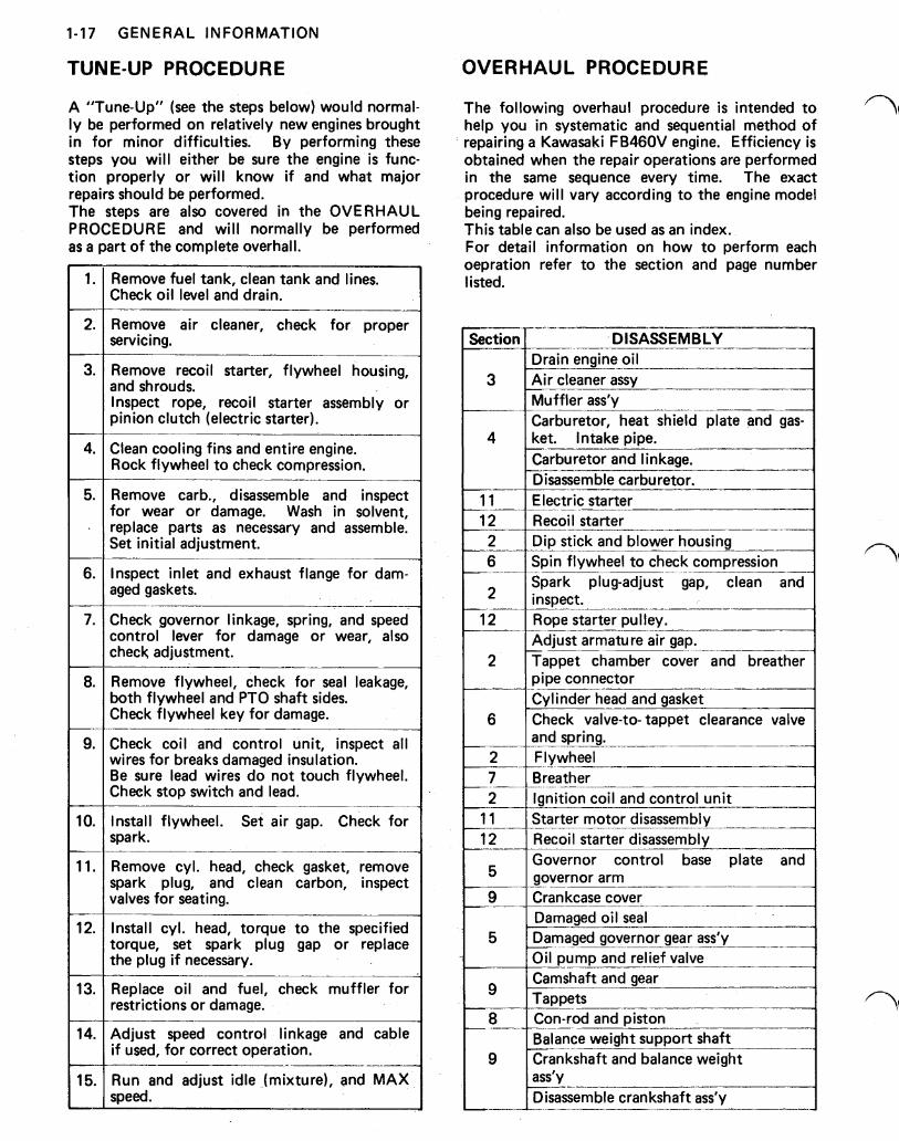
TUNE-UP PROCEDURE
A "Tune-Up" (see the steps below) would normal- ly be performed on relatively new engines brought in for minor difficulties. By performing these steps you will either be sure the engine is func- tion properly or will know if and what major repairs should be performed. The steps are also covered in the OVERHAUL PROCEDURE and will normally be performed as a part of the complete overhall.
Remove fuel tank, clean tank and lines. Check oil level and drain.
Remove air cleaner, check for proper servicing.
Remove recoil starter, flywheel housing, and shrouds. Inspect rope, recoil starter assembly or pinion clutch (electric starter).
Clean cooling fins and entire engine. Rock flywheel to check compression.
Remove carb., disassemble and inspect for wear or damage. Wash in solvent, replace parts as necessary and assemble. Set initial adjustment.
Inspect inlet and exhaust flange for dam- aged gaskets.
Check governor linkage, spring, and speed control lever for damage or wear, also check adjustment.
Remove flywheel, check for seal leakage, both flywheel and PTO shaft sides. Check flywheel key for damage.
Check coil and control unit, inspect all wires for breaks damaged insulation. Be sure lead wires do not touch flywheel. Check stop switch and lead.
Install flywheel. Set air gap. Check for spark.
Remove cyl. head, check gasket, remove spark plug, and clean carbon, inspect valves for seating.
Install cyl. head, torque to the specified torque, set spark plug gap or replace the plug if necessary.
Replace oil and fuel, check muffler for restrictions or damage.
Adjust speed control linkage and cable if used, for correct operation.
Run and adjust idle (mixture), and MAX speed.
OVERHAUL PROCEDURE
The following overhaul procedure is intended to help you in systematic and sequential method of repairing a Kawasaki FB46OV engine. Efficiency is obtained when the repair operations are performed in the same sequence every time. The exact procedure will vary according to the engine model being repaired. This table can also be used as an index. For detail information on how to perform each operation refer to the section and page number listed.
DISASSEMBLY Drain engine oil Air cleaner assy Muffler ass'y Carburetor, heat shield plate and gas- ket. Intake pipe.
__
Carburetor and linkage. Disassemble carburetor.
I_______-
Electric starter Recoil starter Dip stick and blower housing Spin flywheel to check compression Spark plug-adjust gap, inspect. clean and I Rope starter pulley. Adjust armature air gap. Tappet chamber cover and pipe connector Cylinder head and gasket Check valve-to- tappet clearance valve and spring. Flywheel Breather _-
Ignition coil and control unit Starter motor disassembly Recoil starter disassembly Governor control base plate and governor arm Crankcase cover Damaged oil seal Damaged governor gear ass'y Oil pump and relief valve Camshaft and gear Tappets Con-rod and piston Balance weight support shaft Crankshaft and balance weight ass'y Disassemble crankshaft ass'y I
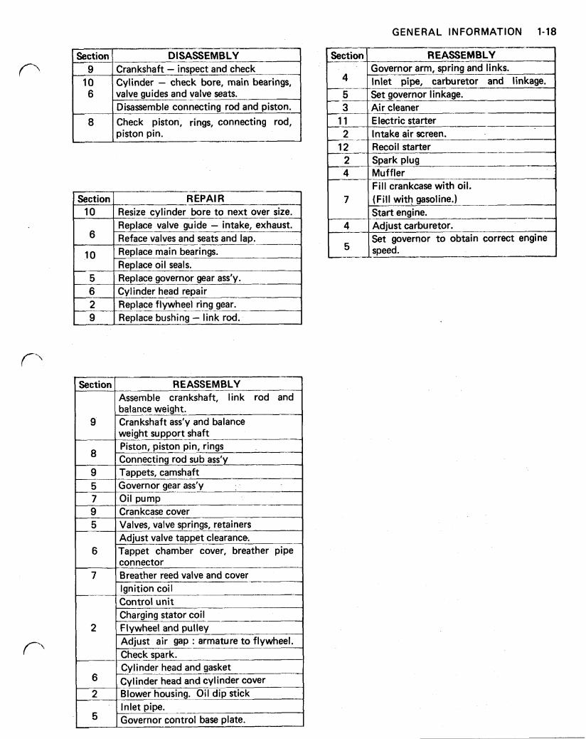
GENERAL INFORMATION 1-18
Section DISASSEMBLY 9
10 Crankshaft inspect and check
valve guides and valve seats. 6 Cylinder check bore, main bearings,
Disassemble connecting rod and piston. 8 Check piston, rings, connecting rod,
piston pin.
I Section R EPAl R Resize cylinder bore to next over size. Replace valve guide intake, exhaust. Reface valves and seats and lap. I Replace main bearings. Replace oil seals. Replace governor gear ass'y. Cylinder head repair
2 Replace bushing link rod. 9 Replace flywheel ring gear.
REASSEMBLY Section
9
Assemble crankshaft, link rod and balance weight. Crankshaft ass'y and balance weight support shaft
8 Piston, piston pin, rings Connecting rod sub ass'y Tappets, camshaft Governor gear ass’y
9 5 7 9 Crankcase cover
Valves, valve springs, retainers Adjust valve tappet clearance. Tappet chamber cover, breather pipe connector Breather reed valve and cover
5
6
7 lgnition coil ~- Control unit Charging stator coil
2 Flywheel and pulley Adjust air gap : armature to flywheel. Check spark. Cylinder head and gasket Cylinder head and cylinder cover Blower housing. Oil dip stick Inlet pipe. Governor control base plate.
2-1 IGNITION
Section 2
IGNITION
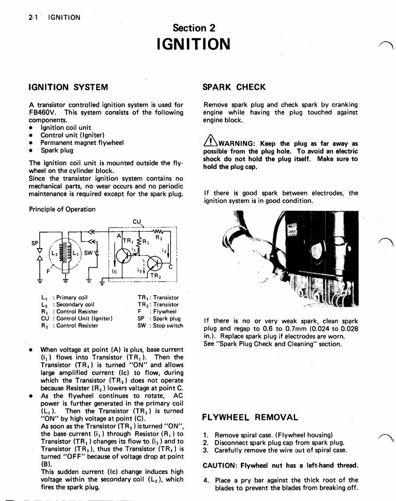
IGNITION SYSTEM
A transistor controlled ignition system is used for FB46OV. This system consists of the following components.
Ignition coil unit Control unit (Igniter) Permanent magnet flywheel Spark plug
The ignition coil unit is mounted outside the fly- wheel on the cylinder block. Since the transistor ignition system contains no mechanical parts, no wear occurs and no periodic maintenance is required except for the spark plug.
Principle of Operation
: Primary coil : Secondary coil
: Transistor : Transistor
: Control Resister F : Flywheel CU : Control Unit (Igniter) SP : Spark plug
: Control Resister SW : Stop switch
When voltage a t point (A) is plus, base current ) flows into Transistor ). Then the
Transistor is turned "ON" and allows large amplified current to flow, during which the Transistor does not operate because Resister ( ) lowers valtage a t point C. As the flywheel continues to rotate, AC power is further generated in the primary coil (L, ). Then the Transistor ) is turned "ON" by high voltage a t point (C). As soon as the Transistor ) is turned "ON", the base current ) through Resistor ( R , ) to Transistor ) changes its flow to ) and to Transistor thus the Transistor ) is turned "OFF" because of voltage drop a t point (B). This sudden current change induces high voltage within the secondary coil (L,), which fires the spark plug.
SPARK CHECK
Remove spark plug and check spark by cranking engine while having the plug touched against engine block.
Keep the plug as far away as possible from the plug hole. To avoid an electric shock do not hold the plug itself. Make sure to hold the plug cap.
If there is good spark between electrodes, the ignition system is in good condition.
I f there is no or very weak spark, clean spark plug and regap to 0.6 to 0.7mm (0.024 to 0.028 in.). Replace spark plug if electrodes are worn. See "Spark Plug Check and Cleaning" section.
FLYWHEEL REMOVAL
1. Remove spiral case. (Flywheel housing) 2. Disconnect spark plug cap from spark plug. 3. 'Carefully remove the wire out of spiral case.
CAUTION: Flywheel nut has a left-hand thread.
4. Place a pry bar against the thick root of the blades to prevent the blades from breaking off.
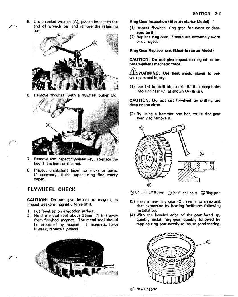
IGNITION 2-2
6. Remove flywheel with a flywheel puller (A).
7. Remove and inspect flywheel key. Replace the key if it is bent or sheared.
8. Inspect crankshaft taper for nicks or burrs. If necessary, finish taper using fine emery paper.
FLYWHEEL CHECK
CAUTION: Do not give impact to magnet, as impact weakens magnetic force of it.
1. Put flywheel on a wooden surface. 2. Hold a metal tool about 25mm (1 in.) away
from flywheel magnet. The metal tool should be attracted by magnet. I f magnetic force is weak, replace flywheel.
CAUTION: Do not cut flywheel by drilling too deep or too close.
(2) By using a hammer and bar, strike ring gear evenly to remove it.
drill 5/16 deep (4-6) drill holes gear
(3) Heat a new ring gear (C), evenly to an extent that expansion by heating facilitates following installation.
(4) With the beveled edge of the gear faced up, quickly install ring gear, quickly followed by tapping ring gear evenly to insure good seating.
New ring gear
2-3 IGNITION
IGNITION COIL CHECK
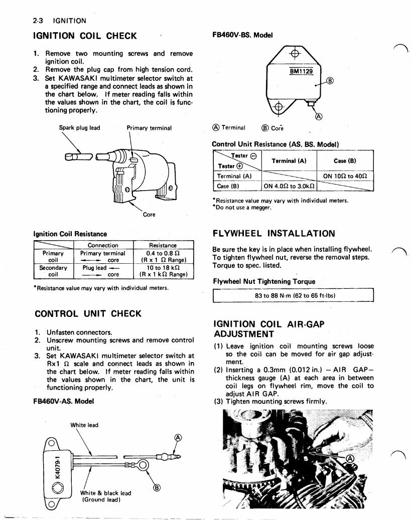
1. Remove two mounting screws and remove
2. Remove the plug cap from high tension cord. 3. Set KAWASAKI multimeter selector switch a t
a specified range and connect leads as shown in the chart below,. I f meter reading falls within the values shown in the chart, the coil is func- tioning properly.
ignition coil.
Spark plug lead Primary terminal
FB460V-BS. Model
BM1129
Terminal Core
Control Unit Resistance (AS. BS, Model)
Terminal (A) Case (B)
Terminal (A) Case (B)
Terminal (A) I Terminal (A) I ON to ON to
*Resistance value may vary with individual meters. *Do not use a megger.
Core
Ignition Coil Resistance FLYWHEEL INSTALLATION Connection I Resistance
I Primary terminal I 0.4 to 0.8 coi I
(R x 1 Range) core coil
(R x 1 Range) core Secondary 10 to 18 Plug lead
*Resistance value may vary with individual meters.
CONTROL UNIT CHECK
1. 2.
3.
Unfasten connectors. Unscrew mounting screws and remove control unit. Set KAWASAKI multimeter selector switch a t Rx1 scale and connect leads as shown in the chart below. If meter reading falls within the values shown in the chart, the unit is functioning properly.
FB460V-AS. Model
White lead
(Ground lead) (Ground lead)
Be sure the key is in place when installing flywheel. To tighten flywheel nut, reverse the removal steps. Torque to spec. listed.
Flywheel Nut Tightening Torque
83 to 88 N-m (62 to 65 ft-lbs)
IGNITION COIL AlR-GAP ADJUSTMENT (1) Leave ignition coil mounting screws loose
so the coil can be moved for air gap adjust- ment.
(2) Inserting a 0.3mm (0.012 in.) AIR GAP- thickness gauge (A) a t each area in between coil legs on flywheel rim, move the coil to adjust AIR GAP.
(3) Tighten mounting screws firmly.
IGNITION 2-4
FLYWHEEL HOUSING INSTALLATION
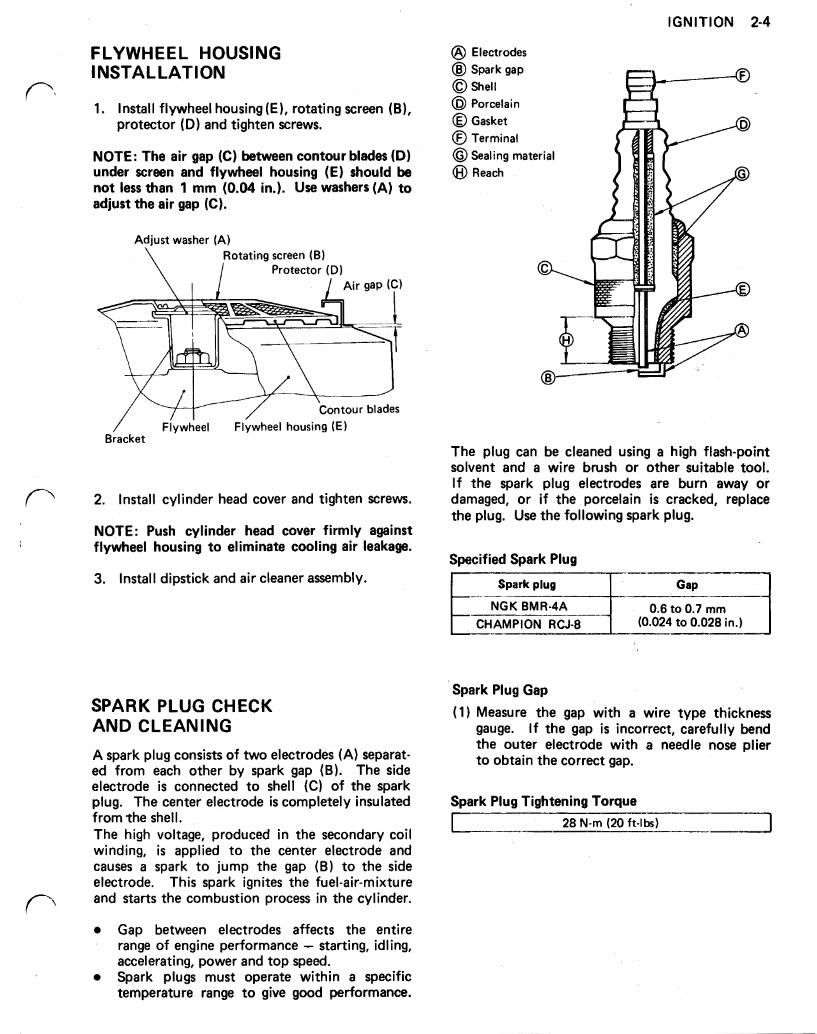
1. Install flywheel housing (E), rotating screen (B), protector (D) and tighten screws.
NOTE: The air gap (C) between contour blades (D) under screen and flywheel housing (E) should be not less than 1 mm (0.04 in.). Use washers (A) to adjust the air gap (C).
Adjust washer (A) Rotating screen (B)
Protector (D) Air gap
Flywheel Flywheel housing Bracket
2. Install cylinder head cover and tighten screws.
NOTE: Push cylinder head cover firmly against flywheel housing to eliminate cooling air leakage.
3. Install dipstick and air cleaner assembly.
Electrodes Spark gap Shell Porcelain Gasket Terminal Seating material Reach
The plug can be cleaned using a high flash-point solvent and a wire brush or other suitable tool. I f the spark plug electrodes are burn away or damaged, or if the porcelain is cracked, replace the plug. Use the following spark plug.
Specified Spark Plug
to 0.028 in.)
Spark plug Gap
NGK BMR-4A 0.6 to 0.7 mm CHAMPION RCJ-8
SPARK PLUG CHECK AND CLEANING A spark plug consists of two electrodes (A) separat- ed from each other by spark gap (B). The side electrode is connected to shell (C) of the spark plug. The center electrode is completely insulated from the shell. The high voltage, produced in the secondary coil winding, is applied to the center electrode and causes a spark to jump the gap (B) to the side electrode. This spark ignites the fuel-air-mixture and starts the combustion process in the cylinder.
Gap between electrodes affects the entire range of engine performance - starting, idling, accelerating, power and top speed. Spark plugs must operate within a specific temperature range to give good performance.
Spark Plug Gap
(1) Measure the gap with a wire type thickness gauge. I f the gap is incorrect, carefully bend the outer electrode with a needle nose plier to obtain the correct gap.
Spark Plug Tightening Torque 28 N-m (20 ft-lbs)
3-1 AIR CLEANER
Section 3 AIR CLEANER
A properly serviced air cleaner protects the internal parts of the engine from dust particles in the air. I f the air cleaner instructions are not carefully followed, the dirt and dust which should be collected in the cleaner, will be drawn into the en- gine and become a part of the oil film, which is very detrimental to engine life; dirt in the oil forms an abrasive mixture which wears the moving parts. The air cleaner on every engine brought in for a check up or repair should be examined and servic- ed. An air cleaner element clogged with dirt chokes the air supply to the engine, resulting in an overly rich fuel/air mixture and inefficient combustion. This in turn causes reduced engine power and overheating due to carbon build-up in combus- tion chamber.
Do not run engine with air cleaner removed.
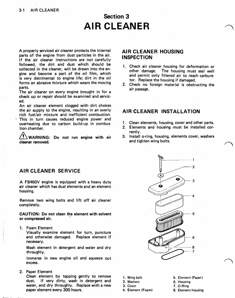
AIR CLEANER SERVICE
A FB460V engine is equipped with a heavy duty air cleaner which has dual elements and an element housing.
Remove two wing bolts and lift off air cleaner completely.
CAUTION: Do not clean the element with solvent or compressed air.
1.
2.
Foam Element Visually examine element for turn, puncture and otherwise damaged. Replace element i f necessary. Wash element in detergent and water and dry throughly. Immerse in new engine oil and squeeze out excess.
AIR CLEANER HOUSING INSPECTION
1. Check air cleaner housing for deformation or other damage. The housing must seal well and permit only filtered air to reach carbure- tor. Replace the housing if damaged.
2. Check no foreign material is obstructing the air passage.
AIR CLEANER INSTALLATION
1. Clean elements, housing, cover and other parts. 2. Elements and housing must be installed cor-
3. Install O-ring, housing, elements cover, washers rectly.
and tighten wing bolts.
Paper Element Clean element by tapping gently to remove 1. Wing bolt 5. Element (Paper) dust. If very dirty, wash in detergent and 2. Washers 6. Housing water, and dry throughly. Replace with a new 3. Cover 7. 0-Ring paper element every 300 hours. 4. Element (Foam) 8. Element housing
CARBURETOR 4-1
Section 4
CARBURETOR
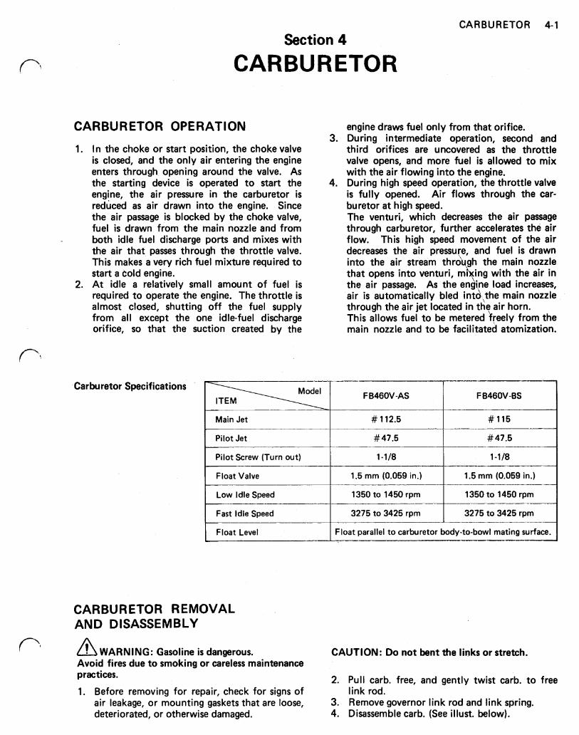
CARBURETOR OPERATION
1. In the choke or start position, the choke valve is closed, and the only air entering the engine enters through opening around the valve. As the starting device is operated to start the engine, the air pressure in the carburetor is reduced as air drawn into the engine. Since the air passage is blocked by the choke valve, fuel is drawn from the main nozzle and from both idle fuel discharge ports and mixes with the air that passes through the throttle valve. This makes a very rich fuel mixture required to start a Cold engine.
2. At idle a relatively small amount of fuel is required to operate the engine. The throttle is almost closed, shutting off the fuel supply from all except the one idle-fuel discharge orifice, so that the suction created by the
Carburetor Specifications
Main Jet
Pilot Jet
Pilot Screw (Turn out)
Float Valve
Low Idle Speed
Fast Idle Speed
engine draws fuel only from that orifice. 3. During intermediate operation, second and
third orifices are uncovered as the throttle valve opens, and more fuel is allowed to mix with the air flowing into the engine.
4. During high speed operation, the throttle valve is fully opened. Air flows through the car- buretor at high speed. The venturi, which decreases the air passage through carburetor, further accelerates the air flow. This high speed movement of the air decreases the air pressure, and fuel is drawn into the air stream thro gh the main nozzle that opens into venturi, mi ing with the air in the air passage. As the en 'ne load increases, air is automatically bled into the main nozzle through the air jet located in the air horn. This allows fuel to be metered freely from the main nozzle and to be facilitated atomization.
F B460V-AS F B46OV-BS
# 47.5 #47.5
1-1/8 I 1 -1/8
1.5 mm (0.059 in.)
1350 to 1450 rpm 1350 to 1450 rpm
1.5 mm (0.059 in.)
3275 to 3425 rpm 3275 to 3425 rpm
Float parallel to carburetor body-to-bowl mating surface.
CARBURETOR REMOVAL AND DISASSEMBLY
WARNING: Gasoline is dangerous. CAUTION: Do not bent the links or stretch. Avoid fires due to smoking or careless maintenance practices.
1. Before removing for repair, check for signs of link rod. 2. Pull carb. free, and gently twist carb. to free
air leakage, or mounting gaskets that are loose, 3. Remove governor link rod and link spring. deteriorated, or otherwise damaged. 4. Disassemble carb. (See illust. below).
4-2 CARBURETOR
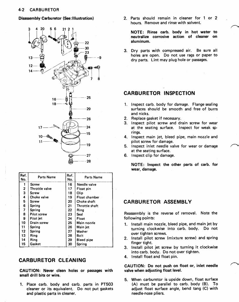
Disassembly Carburetor (See: Illustration)
Ref. Parts Name Ref. No. No.
1
Pilot jet 9 Pilot screw 8 Spring 7 Spring 6 Screw 5 Choke valve 4 Screw 3 Throttle valve 2 Screw
10 Drain screw 11 Spring 12 Spring 13 Ring 14 Ring 15 Gasket
16 17 18 19 20 21 22 23 24 25 26 27 28 29 30
Parts Name
Needle valve Float pin Clip Float chamber Choke shaft Throttle shaft Ring Seal Float Main nozzle Main jet Washer Bolt Bleed pipe Spring
CARBURETOR CLEANING
CAUTION: Never clean holes or passages with small drill bits or wire.
1. Place carb. body and carb. parts in PT503 cleaner or i t s equivalent. Do not put gaskets and plastic parts in cleaner.
2.
3.
Parts should remain in cleaner for 1 or 2 hours. Remove and rinse with solvent.
NOTE: Rinse carb. body in hot water to neutralize corrosive action of cleaner on aluminum.
Dry parts with compressed air. Be sure all holes are open. Do not use rags or paper to dry parts. Lint may plug hole or passages.
CARBURETOR INSPECTION
1.
2. 3.
4.
5.
6.
Inspect carb. body for damage. Flange sealing surfaces should be smooth and free of burrs and nicks. Replace gasket if necessary. Inspect pilot screw and drain screw for wear a t the seating surface. Inspect for weak sp- rings. Inspect main jet, bleed pipe, main nozzle and pilot screw for damage. Inspect inlet needle valve for wear or damage a t the seating surface. Inspect clip for damage.
NOTE: Inspect the other parts of carb. for wear, damage.
CARBURETOR ASSEMBLY
Reassembly is the reverse of removal. Note the following points: 1. Install main nozzle, bleed pipe, and main jet by
turning clockwise into carb. body. Do not over tighten screws.
2. Install pilot screw (mixture screw) and spring finger tight.
3. Install pilot jet screw by turning it clockwise into carb. body. Do not over tighten.
4. Install float and float pin.
CAUTION: Do not push on float or, inlet needle valve when adjusting float level.
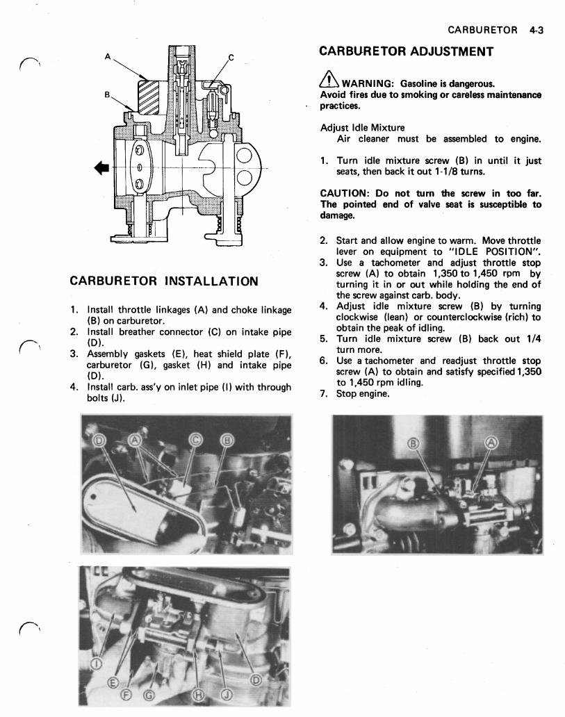
5. When carburetor is upside down, float surface (A) must be parallel to carb. body (B). To adjust float surface angle, bend tang (C) with needle-nose pliers.
CARBURETOR 4-3
CARBURETOR INSTALLATION
1. Install throttle linkages (A) and choke linkage (B) on carburetor.
2. Install breather connector (C) on intake pipe (D).
3. Assembly gaskets (E), heat shield plate (F), carburetor (G), gasket (H) and intake pipe (D).
4. Install carb. ass'y on inlet pipe ( I ) with through bolts (J).
CARBURETOR ADJUSTMENT
WARNING: Gasoline is dangerous. Avoid fires due to smoking or careless maintenance practices.
Adjust Idle Mixture Air cleaner must be assembled to engine.
1. Turn idle mixture screw (B) in until it just seats, then back it out 1-1/8 turns.
CAUTION: Do not turn the screw in too far. The pointed end of valve seat is susceptible to damage.
2. Start and allow engine to warm. Move throttle lever on equipment to "IDLE POSITION".
3. Use a tachometer and adjust throttle stop screw (A) to obtain 1,350 to 1,450 rpm by turning it in or out while holding the end of the screw against carb. body.
4. Adjust idle mixture screw (B) by turning clockwise (lean) or counterclockwise (rich) to obtain the peak of idling.
5. Turn idle mixture screw (B) back out 1/4 turn more.
6. Use a tachometer and readjust throttle stop screw (A) to obtain and satisfy specified 1,350 to 1,450 rpm idling.
7. Stop engine.
5-1 GOVERNOR
Section 5
GOVERNOR
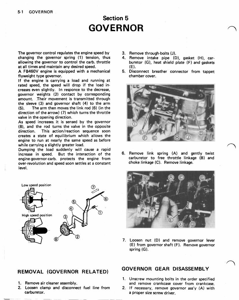
The governor control regulates the engine speed by 3. Remove through-bolts (J). changing the governor spring (1) tension, thus 4. Remove intake pipe (D), gasket (H), car- allowing the governor to control the carb. throttle buretor (GI, heat shield plate (F) and gaskets a t all times and maintain any desired speed. (E). A FB46OV engine is equipped with a mechanical 5. Disconnect breather connector from tappet flyweight type governor. chamber cover. I f the engine is carrying a load and running a t rated speed, the speed will drop i f the load in- creases even slightly. In responce to the decrease, governor weights (2) contact by corresponding amount. Their movement is transmitted through the sleeve (3) and governor shaft (4) to the arm (5). The arm then moves the link rod (6) (in the direction of the arrow) (7) which turns the throttle valve in the opening direction. As speed increases, it is sensed by the governor (8), and the rod turns the valve in the opposite direction. This action/reaction sequence soon creates a state of equilibrium which allows the engine to run a t nearly the same speed as before while carrying a slightly greater load. Dumping the load suddenly will cause a rapid increase in speed. But the interaction of the 6 . Remove link spring (A) and gently twist engine-governor-carb. protects the engine from carburetor to free throttle linkage (B) and over-revolution and speed soon settles a t a constant choke linkage (C). Remove linkage. level.
Low speed position
High speed position
REMOVAL (GOVERNOR RELATED) GOVERNOR GEAR DISASSEMBLY
1. Unscrew mounting bolts in the order specified 1. Remove air cleaner assembly. and remove crankcase cover from crankcase. 2. Loosen clamp and disconnect fuel line from 2. I f necessary, remove governor ass’y (A) with
carburetor. a proper size screw driver.
GOVERNOR 5-2
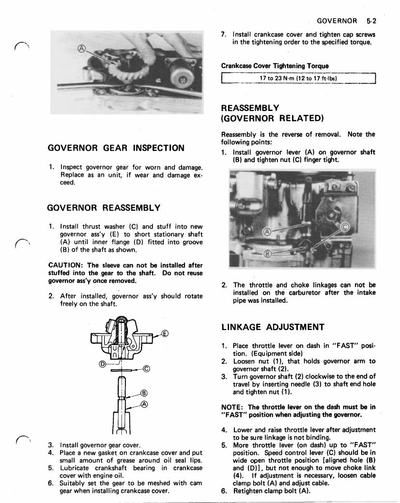
GOVERNOR GEAR INSPECTION
1. Inspect governor gear for worn and damage. Replace as an unit, if wear and damage ex- ceed.
GOVERNOR REASSEMBLY
1. Install thrust washer (C) and stuff into new governor ass'y (E) to short stationary shaft (A) until inner flange (D) fitted into groove (B) of the shaft as shown.
CAUTION: The sleeve can not be installed after stuffed into the gear to the shaft. Do not reuse governor ass'y once removed.
2. After installed, governor ass'y should rotate freely on the shaft.
3. I nstall governor gear cover. 4. Place a new gasket on crankcase cover and put
small amount of grease around oil seal lips. 5. Lubricate crankshaft bearing in crankcase
cover with engine oil. 6. Suitably set the gear to be meshed with cam
gear when installing crankcase cover.
Reassembly is the reverse of removal. Note the following points: 1. Install governor lever (A) on governor shaft
(B) and tighten nut (C) finger tight.
2. The throttle and choke linkages can not be installed on the carburetor after the intake pipe was installed.
LINKAGE ADJUSTMENT
1. Place throttle lever on dash in "FAST" posi- tion. (Equipment side)
2. Loosen nut (1), that holds governor arm to governor shaft (2).
3. Turn governor shaft (2) clockwise to the end of travel by inserting needle (3) to shaft end hole and tighten nut (1).
NOTE: The throttle lever on the dash must be in "FAST" position when adjusting the governor.
4. Lower and raise throttle lever after adjustment to be sure linkage is not binding.
5. More throttle lever (on dash) up to "FAST" position. Speed control lever (C) should be in wide open throttle position [aligned hole (B) and (D)], but not enough to move choke link (4). I f adjustment is necessary, loosen cable clamp bolt (A) and adjust cable.
6. Retighten clamp bolt (A).
5-3 GOVERNOR
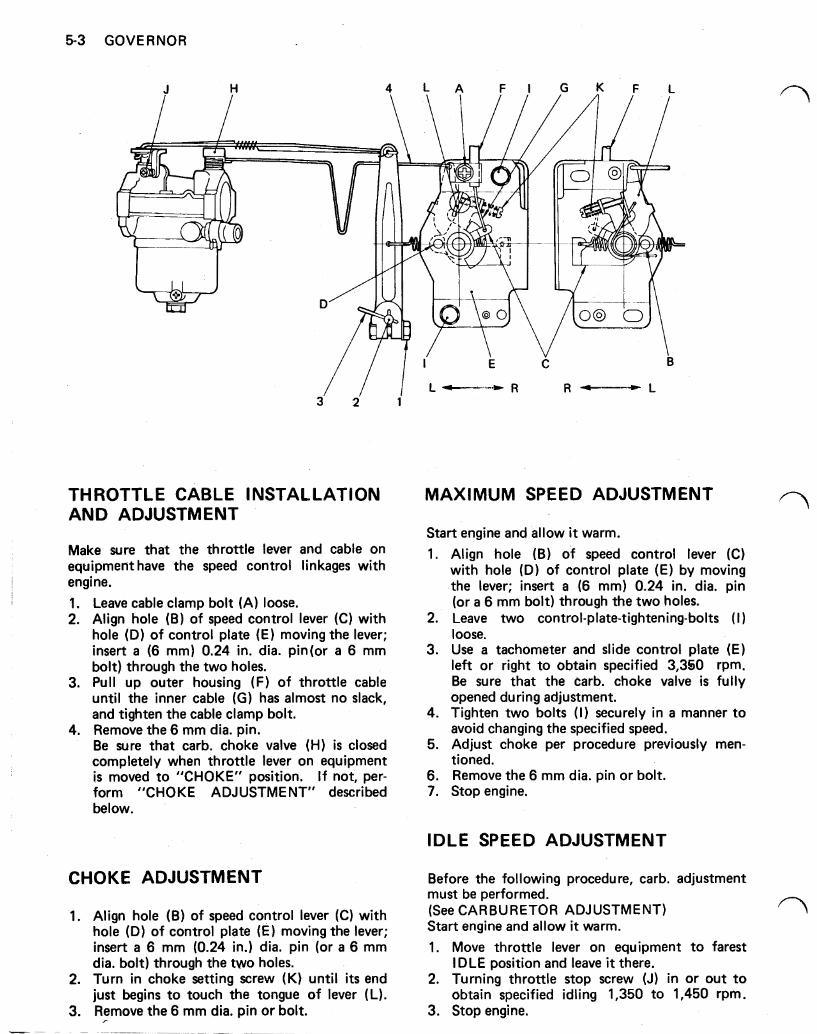
THROTTLE CABLE INSTALLATION AND ADJUSTMENT
Make sure that the throttle lever and cable on equipment have the speed control linkages with engine. 1. 2.
3.
4.
Leave cable clamp bolt (A) loose. Align hole (B) of speed control lever (C) with hole (D) of control plate (E) moving the lever; insert a (6 mm) 0.24 in. dia. pin (or a 6 mm bolt) through the two holes. Pull up outer housing (F) of throttle cable until the inner cable (G) has almost no slack, and tighten the cable clamp bolt. Remove the 6 mm dia. pin. Be sure that carb. choke valve (H) is closed completely when throttle lever on equipment is moved to "CHOKE" position. If not, per- form "CHOKE ADJUSTMENT,, described below.
CHOKE ADJUSTMENT
1. Align hole (B) of speed control lever (C) with hole (D) of control plate (E) moving the lever; insert a 6 mm (0.24 in.) dia. pin (or a 6 mm dia. bolt) through the two holes.
2. Turn in choke setting screw (K) until i ts end just begins to touch the tongue of lever (L).
3. Remove the 6 mm dia. pin or bolt.
MAXIMUM SPEED ADJUSTMENT
Start engine and allow it warm. 1. Align hole (B) of speed control lever (C)
with hole (D) of control plate (E) by moving the lever; insert a (6 mm) 0.24 in. dia. pin (or a 6 mm bolt) through the two holes.
2. Leave two control-plate-tightening-bolts ( I ) loose.
3. Use a tachometer and slide control plate (E) lef t or right to obtain specified 3,350 rpm. Be sure that the carb. choke valve is fully opened during adjustment.
4. Tighten two bolts (I) securely in a manner to avoid changing the specified speed.
5. Adjust choke per procedure previously men- tioned.
6. Remove the 6 mm dia. pin or bolt. 7. Stop engine.
IDLE SPEED ADJUSTMENT
Before the following procedure, carb. adjustment must be performed. (See CARBURETOR ADJUSTMENT) Start engine and allow it warm. 1. Move throttle lever on equipment to farest
IDLE position and leave it there. 2. Turning throttle stop screw (J) in or out to
obtain specified idling 1,350 to 1,450 rpm. 3. Stop engine.
COMPRESSION 6-1
Section 6
COMPRESSION
COMPRESSION CHECK
Before measuring compression pressure; Check cyl. head to torque. Be sure battery is fully charged on electric starter models. Start engine and allow it to warm up. During warm up, check for leaks around cyl. head gasket. Stop engine.
1. Remove spark plug and screws compression gauge into the plug hole securely.
2. Crank engine with recoil or electric starting for several seconds and take highest pressure gauge reading. Cylinder compression should not be less than 3 kg/cm² (43 psi).
3. I f compression reading is too high, check for carbon built up in combustion chamber. Carbon deposits in combustion chamber should be removed every 100 to 200 hours of. use, or whenever cyl. head is removed.
4. I f the compression pressure is less than spe- cified, it is usually the result of one or more of:
Leaking cyl. head gasket. Warped cyl. head. Worn piston rings. Damaged piston. Worn cyl. bore. Burned or warped valves. Improper valve clearance. Broken valve springs. To a great extent, compression can also be practically measured by:
Disconnect spark plug cap to prevent engine starting during compression test. Be careful not to get your fingers caught in fly- wheel fins during test.
Spin flywheel counter clockwise (flywheel side) against the compression stroke; a sharp rebound indicates satisfactory compression. Slight or no rebound indicates poor compression.
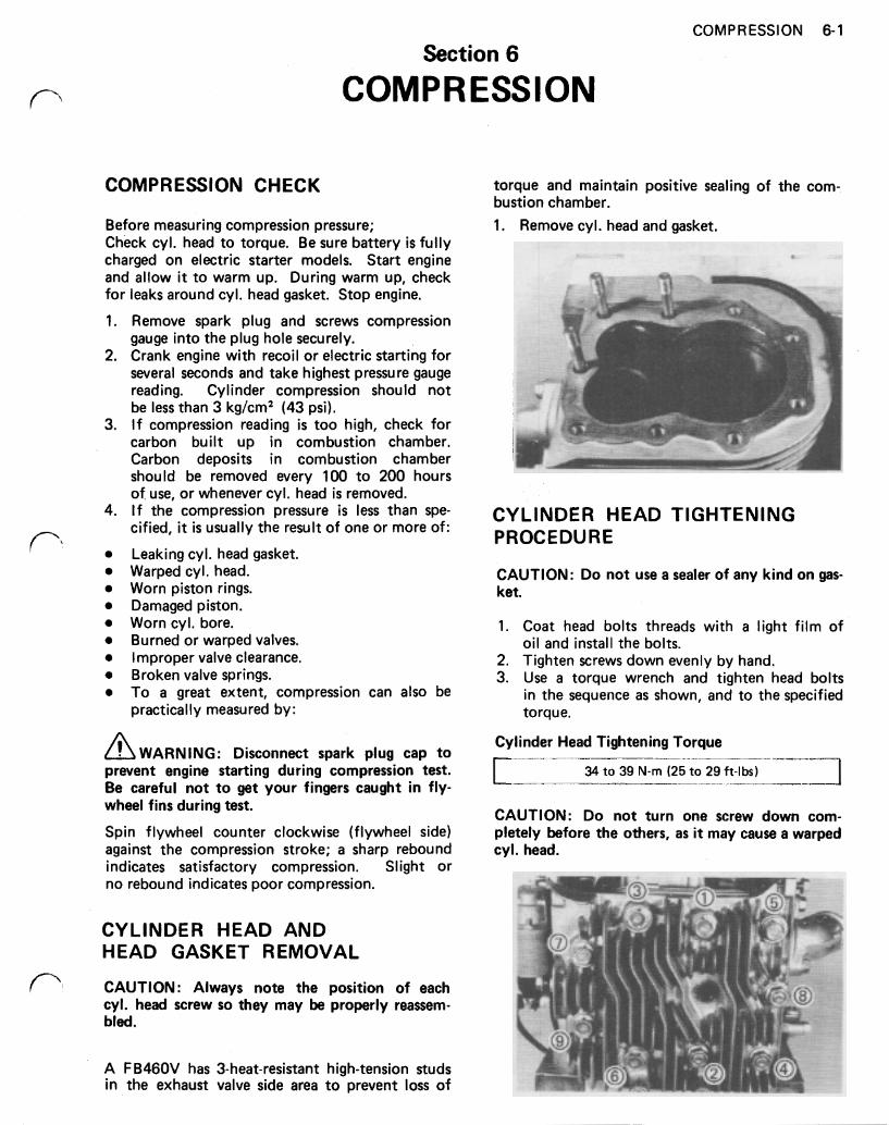
CYLINDER HEAD AND HEAD GASKET REMOVAL
CAUTION: Always note the position of each cyl. head screw so they may be properly reassem- bled.
torque and maintain positive sealing of the com- bustion chamber. 1. Remove cyl. head and gasket.
*-
CYLINDER HEAD TIGHTENING PROCEDURE
CAUTION: Do not use a sealer of any kind on gas- ket.
1. Coat head bolts threads with a light film of
2. Tighten screws down evenly by hand. 3. Use a torque wrench and tighten head bolts
in the sequence as shown, and to the specified torque.
oil and install the bolts.
Cylinder Head Tightening Torque
L 34 to 39 N-m (25 to 29 ft-lbs)
CAUTION: Do not turn one screw down com- pletely before the others, as it may cause a warped cyl. head.
A FB46OV has 3-heat-resistant high-tension studs in the exhaust valve side area to prevent loss of
6-2 COMPRESSION
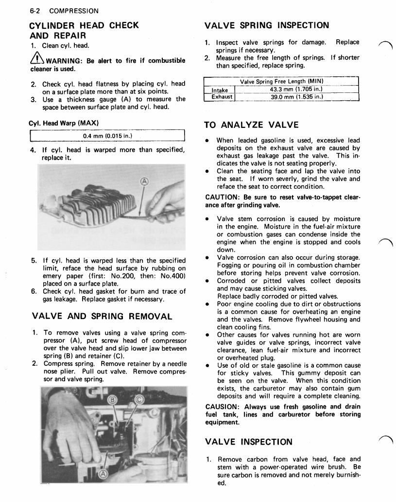
CYLINDER HEAD CHECK AND REPAl R 1. Clean cyl. head.
WARNING: Be alert to fire i f combustible cleaner is used.
2. Check cyl. head flatness by placing cyl. head on a surface plate more than a t six points.
3. Use a thickness gauge (A) to measure the space between surface plate and cyl. head.
Cyl. Head Warp (MAX)
0.4 mm (0.01 5 in.) I I J
4. If cyl. head is warped more than specified, replace it.
5. I f cyl. head is warped less than the specified limit, reface the head surface by rubbing on emery paper (first: No. 200, then: No. 400) placed on a surface plate.
6. Check cyl. head gasket for burn and trace of gas leakage. Replace gasket if necessary.
VALVE AND SPRING REMOVAL
1. To remove valves using a valve spring com- pressor (A), put screw head of compressor over the valve head and slip lower jaw between spring (B) and retainer (C).
2. Compress spring. Remove retainer by a needle nose plier. Pull out valve. Remove compres- sor and valve spring.
VALVE SPRING INSPECTION
1. Inspect valve springs for damage. Replace
2. Measure the free length of springs. I f shorter springs if necessary.
than specified, replace spring.
Valve Spring Free Length (MIN) Intake I 43.3 mm (1.705 in.) Exhaust 39.0 mm (1.535 in.)
TO ANALYZE VALVE
When leaded gasoline is used, excessive lead deposits on the exhaust valve are caused by exhaust gas leakage past the valve. This in- dicates the valve is not seating properly. Clean the seating face and lap the valve into the seat. I f worn severly, grind the valve and reface the seat to correct condition.
CAUTION: Be sure to reset valve-to-tappet clear- ance after grinding valve.
Valve stem corrosion is caused by moisture in the engine. Moisture in the fuel-air mixture or combustion gases can condense inside the engine when the engine is stopped and cools down. Valve corrosion can also occur during storage. Fogging or pouring oil in combustion chamber before storing helps prevent valve corrosion. Corroded or pitted valves collect deposits and may cause sticking valves. Replace badly corroded or pitted valves. Poor engine cooling due to dirt or obstructions is a common cause for overheating an engine and the valves. Remove flywheel housing and clean cooling fins. Other causes for valves running hot are worn valve guides or valve springs, incorrect valve clearance, lean fuel-air mixture and incorrect or overheated plug. Use of old or stale gasoline is a common cause for sticky valves. This gummy deposit can be seen on the valve. When this condition exists, the carburetor may also contain gum deposits and will require a complete cleaning.
CAUTION: Always use fresh gasoline and drain fuel tank, lines and carburetor before storing equipment.
VALVE INSPECTION
1. Remove carbon from valve head, face and stem with a power-operated wire brush. Be sure carbon is removed and not merely burnish- ed.
COMPRESSION 6-3
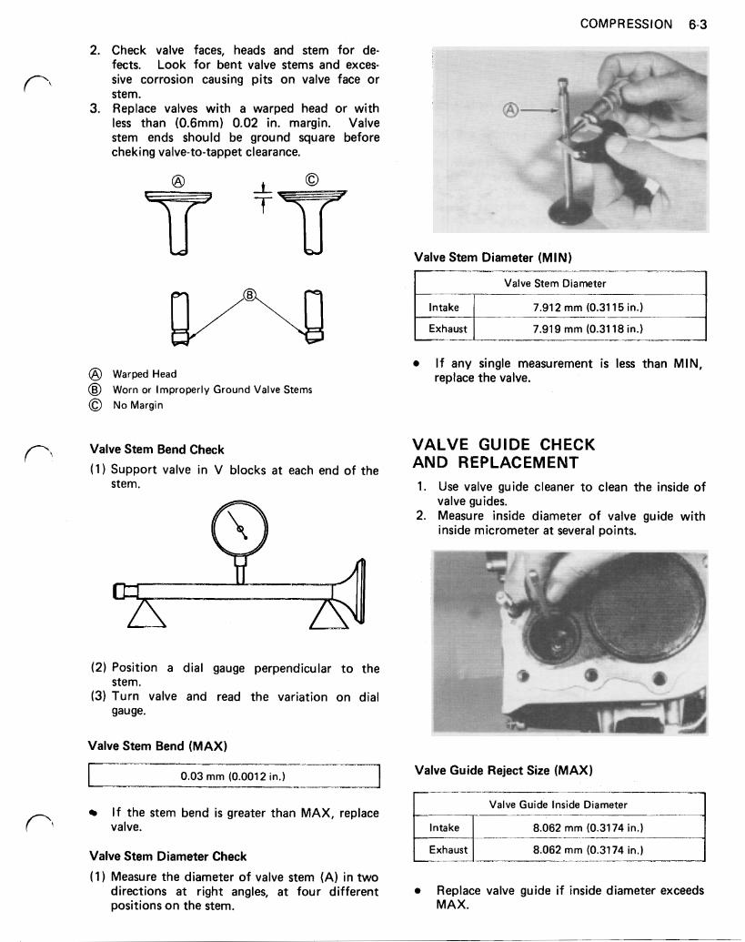
2. Check valve faces, heads and stem for de- fects. Look for bent valve stems and exces- sive corrosion causing pits on valve face or stem.
3. Replace valves with a warped head or with less than (0.6mm) 0.02 in. margin. Valve stem ends should be ground square before checking valve-to-tappet clearance.
Valve Stem Diameter (MIN)
Valve Stem Diameter
7.91 2 mm (0.31 15 in.)
Warped Head Worn or Improperly Ground Valve Stems No Margin
Valve Stem Bend Check
(1 ) Support valve in V blocks a t each end of the stem.
(2) Position a dial gauge perpendicular to the
(3) Turn valve and read the variation on dial stem.
gauge.
I f any single measurement is less than MIN, replace the valve.
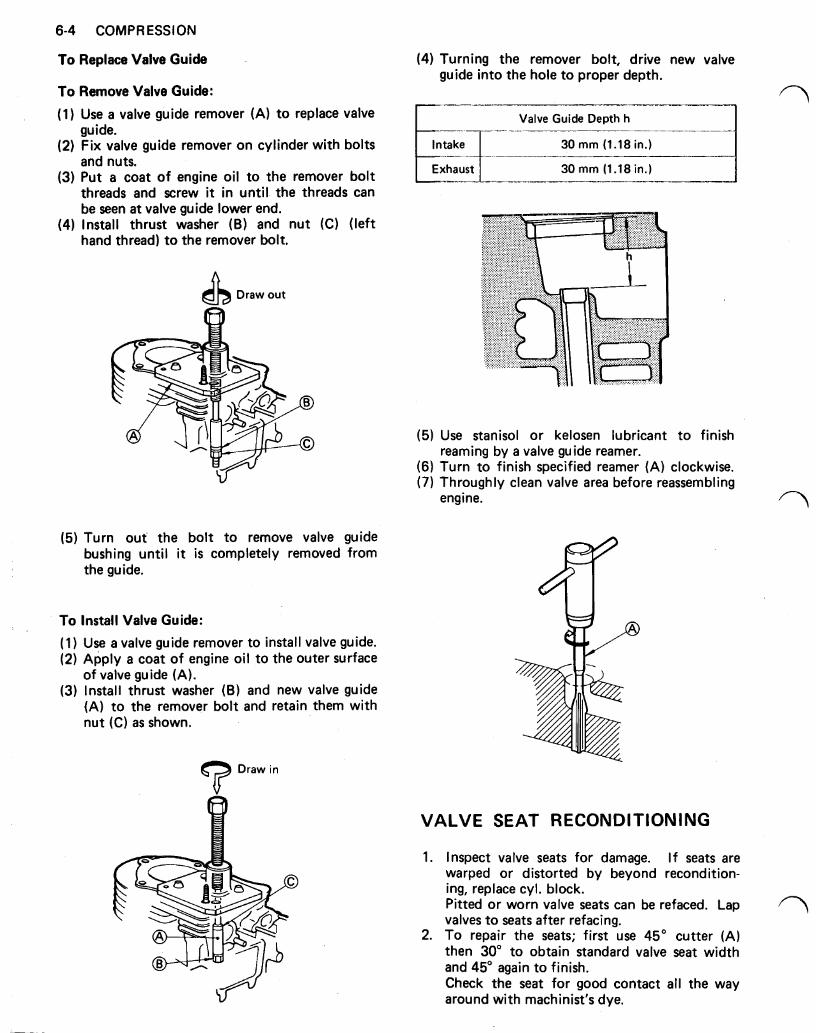
VALVE GUIDE CHECK AND REPLACEMENT 1. Use valve guide cleaner to clean the inside of
2. Measure inside diameter of valve guide with valve guides.
inside micrometer a t several points.
Valve Stem Bend (MAX)
0.03 mm (0.001 2 in.)
If the stem bend is greater than MAX, replace valve.
Valve Stem Diameter Check
(1 ) Measure the diameter of valve stem (A) in two directions a t right angles, a t four different positions on the stem.
Valve Guide Reject Size (MAX)
Valve Guide Inside Diameter
Intake 8.062 mm (0.3174 in.)
8.062 mm (0.3174 in.)
Replace valve guide if inside diameter exceeds MAX.
6-4 COMPRESSION
To Replace Valve Guide
To Remove Valve Guide:
(1 ) Use a valve guide remover guide.
(A) to replace valve
(2) Fix valve guide remover on cylinder with bolts and nuts.
(3) Put a coat of engine oil to the remover bolt threads and screw it in until the threads can be seen a t valve guide lower end.
(4) Install thrust washer (B) and nut (C) (left hand thread) to the remover bolt.
Draw out
(5) Turn out the bolt to remove valve guide bushing until it is completely removed from the guide.
To Install Valve Guide:
(1) Use a valve guide remover to install valve guide. (2) Apply a coat of engine oil to the outer surface
of valve guide (A). (3) Install thrust washer (B) and new valve guide
(A) to the remover bolt and retain them with nut (C) as shown.
Draw in
(4) Turning the remover bolt, drive new valve guide into the hole to proper depth.
Valve Guide Depth h
30 mm (1.18 in.)
Exhaust 30 mm (1.18 in.)
(5) Use stanisol or kelosen lubricant to finish
(6) Turn to finish specified reamer (A) clockwise. (7) Throughly clean valve area before reassembling
reaming by a valve guide reamer.
engine.
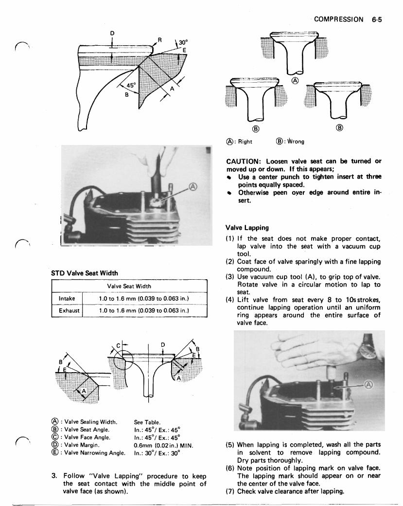
VALVE SEAT RECONDITIONING
1. Inspect valve seats for damage. I f seats are warped or distorted by beyond recondition- ing, replace cyl. block. Pitted or worn valve seats can be refaced. Lap valves to seats after refacing.
2. To repair the seats; first use 45" cutter (A) then 30" to obtain standard valve seat width and 45" again to finish. Check the seat for good contact all the way around with machinist's dye.
COMPRESSION 6-5
D
\
Right : Wrong
CAUTION: Loosen valve seat can be turned or moved up or down. If this appears;
Use a center punch to tighten insert at three
Otherwise peen over edge around entire in- points equally spaced.
sert.
Valve Lapping
( 1 ) If the seat does not make proper contact, lap valve into the seat with a vacuum cup tool.
(2) Coat face of valve sparingly with a fine lapping
STD Valve Seat Width compound. (3) Use vacuum cup tool (A), to grip top of valve.
I Valve Seat Width Rotate valve in a circular motion to lap to I I seat.
Intake continue lapping operation until an uniform 1 .0 to 1.6 mm (0.039 to 0.063 in.) Exhaust
(4) Lift valve from seat every 8 to 10s strokes, 1 .0 to 1.6 mm (0.039 to 0.063 in.)
ring appears around the entire surface of
: Valve Sealing Width. See Table. : Valve Seat Angle. In.: 45°/ Ex.: 45"
valve face.
: Valve Face Angle. In.: 45°/ Ex.: 45° : Valve Margin. 0.6mm (0.02 in.) MIN. (5) When lapping is completed, wash all the parts : Valve Narrowing Angle. In.: 30°/ Ex.: 30° in solvent to remove lapping compound.
(6) Note position of lapping mark on valve face. 3. Follow "Valve Lapping" procedure to keep The lapping mark should appear on or near
Dry parts thoroughly.
the seat contact with the middle point of the center of the valve face. valve face (as shown). (7) Check valve clearance after lapping.
6-6 COMPRESSION
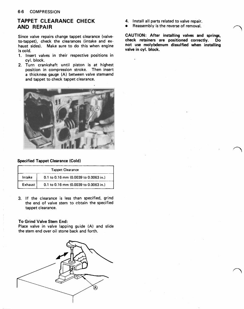
TAPPET CLEARANCE CHECK 4. Install all parts related to valve repair. AND REPAIR Reassembly is the reverse of removal.
Since valve repairs change tappet clearance (valve- CAUTION: After installing valves and springs, to-tappet), check the clearances (intake and ex- check retainers are positioned Correctly. D O
haust sides). Make Sure to do this when engine not Use molybdenum dissulfied when installing is cold. valve in cyl. block. 1. Insert valves in their respective positions in
cyl. block. 2. Turn crankshaft until piston is a t highest
position in compression stroke. Then insert a thickness gauge (A) between valve stemsend and tappet to check tappet clearance.
Specified Tappet Clearance (Cold)
Tappet Clearance
3. If the clearance is less than specified, grind the end of valve stem to obtain the specified tappet clearance.
To Grind Valve Stem End: Place valve in valve lapping guide (A) and slide the stem end over oil stone back and forth.
LUBRICATION 7-1
Section 7
LUBRICATION
LUBRICATION
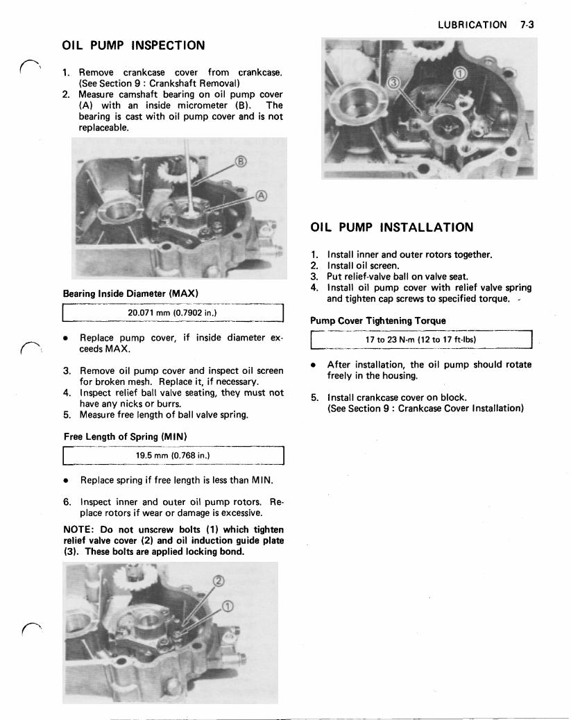
Oil has four purposes. It cools, cleans, seals and lubricates. A pressurized lubrication system used on the FB460V engine pressure-lubricates the crank pin, PTO main journal and balancer link.
The FB46OV utilizes a camshaft driven trochoid pump to pressurize the lubrication system. Oil is first drawn through a filtering screen (1) then the inlet (2) and into the pump chamber (3). Oil pressure is adjusted by a relief valve (8 ) to a value of above (3 kg/cm² ) 42.6 psi a t 3,000 rpm (Rated speed). The oil is then pumped to the PTO main journal (4) into crankshaft and lubricates the lower link rod (5), crank pin (6) and upper link rod journal (7). A portion of oil a t the crank pin is passed through a metered orifice in the connect- ing rod and is sprayed on the piston to cool the piston and prevent ring sticking. The return oil mists then lubricates the magneto side ball bearing and others.
OIL WARNING SYSTEM (Electric Starter Model only)
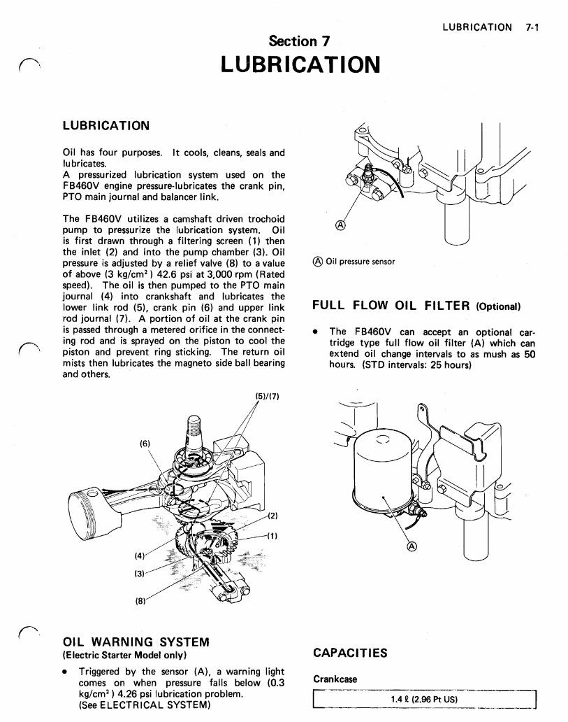
Triggered by the sensor (A), a warning light comes on when pressure falls below (0.3 kg/cm² ) 4.26 psi lubrication problem. (See ELECTRICAL SYSTEM)
I I
Oil pressure sensor
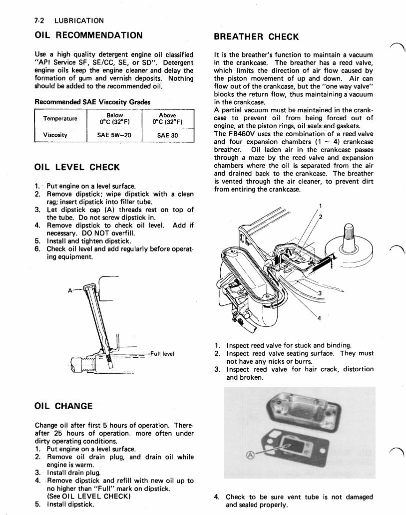
FULL FLOW OIL FILTER (Optional)
The FB46OV can accept an optional car- tridge type full flow oil filter (A) which can extend oil change intervals to as mush as 50 hours. (STD intervals: 25 hours)
IE CAPACIT
Crankcase
S
1.4 (2.96 Pt US)
7-2 LUBRICATION
OIL RECOMMENDATION
Use a high quality detergent engine oil classified "API Service SF, SE/CC, SE, or SD". Detergent engine oils keep the engine cleaner and delay the formation of gum and vernish deposits. Nothing should be added to the recommended oil.
Recommended SAE Viscosity Grades I
Temperature Below Above 0°C (32°F) 0°C (32°F) I
I I I
Viscosity SAE 5W-20 SAE 30
OIL LEVEL CHECK
1. Put engine on a level surface. 2. Remove dipstick; wipe dipstick with a clean
3. Let dipstick cap (A) threads rest on top of
4. Remove dipstick to check oil level. Add if
5. Install and tighten dipstick. 6. Check oil level and add regularly before operat-
rag; insert dipstick into filler tube.
the tube. Do not screw dipstick in.
necessary. DO NOT overfill.
ing equipment.
Full level
OIL CHANGE
Change oil after first 5 hours of operation. There- after 25 hours of operation; more often under dirty operating conditions. 1. Put engine on a level surface. 2. Remove oil drain plug, and drain oil while
3. Install drain plug. 4. .Remove dipstick and refill with new oil up to
engine is warm.
no higher than "Full" mark on dipstick. (See OI L LEVEL CHECK)
5. Install dipstick.
BREATHER CHECK
It is the breather's function to maintain a vacuum in the crankcase. The breather has a reed valve, which limits the direction of air flow caused by the piston movement of up and down. Air can flow out of the crankcase, but the "one way valve" blocks the return flow, thus maintaining a vacuum in the crankcase. A partial vacuum must be maintained in the crank- case to prevent oil from being forced out of engine, a t the piston rings, oil seals and gaskets. The FB460V uses the combination of a reed valve and four expansion chambers ( 1 4) crankcase breather. Oil laden air in the crankcase passes through a maze by the reed valve and expansion chambers where the oil is separated from the air and drained back to the crankcase. The breather is vented through the air cleaner, to prevent dirt from entering the crankcase.
1. Inspect reed valve for stuck and binding. 2. Inspect reed valve seating surface. They must
3. Inspect reed valve for hair crack, distortion not have any nicks or burrs.
and broken.
4. Check to be sure vent tube is not damaged and sealed properly.
LUBRICATION 7-3
OIL PUMP INSPECTION
1. Remove crankcase cover from crankcase. (See Section 9 : Crankshaft Removal)
2. Measure camshaft bearing on oil pump cover (A) with an inside micrometer (B). The bearing is cast with oil pump cover and is not replaceable.
t
Bearing Inside Diameter (MAX)
I 20.071 mm (0.7902 in.)
Replace pump cover, if inside diameter ex- ceeds MAX.
3. Remove oil pump cover and inspect oil screen
4. Inspect relief ball valve seating, they must not
5. Measure free length of ball valve spring.
Free Length of Spring (MIN)
for broken mesh. Replace it, i f necessary.
have any nicks or burrs.
19.5 mm (0.768 in.) ._______- I
Replace spring if free length is less than MIN.
6. Inspect inner and outer oil pump rotors. Re- place rotors i f wear or damage is excessive.
NOTE: Do not unscrew bolts (1) which tighten relief valve cover (2) and oil induction guide plate (3). These bolts are applied locking bond.
OIL PUMP INSTALLATION
1. Install inner and outer rotors together. 2. Install oil screen. 3. Put relief-valve ball on valve seat. 4. Install oil pump cover with relief valve spring
and tighten cap screws to specified torque.
Pump Cover Tightening Torque
___-- 17 to 23 N-m (12 to 17 ft-lbs)
After installation, the oil pump should rotate freely in the housing.
5. Install crankcase cover on block. (See Section 9 : Crankcase Cover Installation)
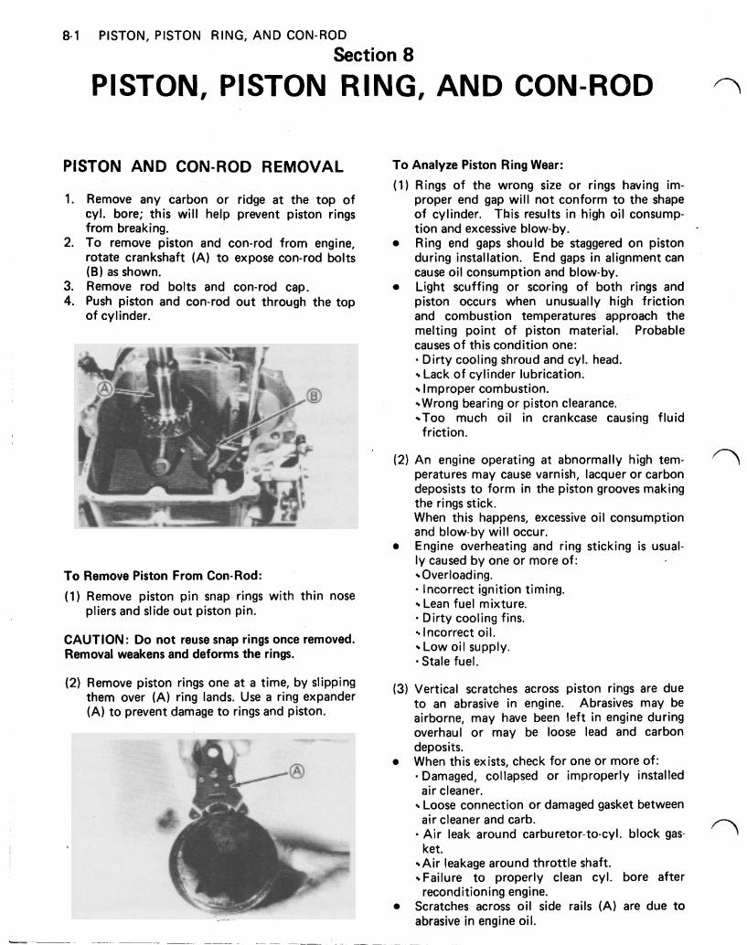
8-1 PISTON, PISTON RING, AND CON-ROD
Section 8
PISTON, PISTON RING, AND CON-ROD
PISTON AND CON-ROD REMOVAL To Analyze Piston Ring Wear:
1.
2.
3. 4.
Remove any carbon or ridge a t the top of cyl. bore; this will help prevent piston rings from breaking. To remove piston and con-rod from engine, rotate crankshaft (A) to expose con-rod bolts (B) as shown. Remove rod bolts and con-rod cap. Push piston and con-rod out through the top of cylinder.
To Remove Piston From Con-Rod:
(1) Remove piston pin snap rings with thin nose pliers and slide out piston pin.
CAUTION: Do not reuse snap rings once removed. Removal weakens and deforms the rings.
(2) Remove piston rings one at a time, by slipping them over (A) ring lands. Use a ring expander (A) to prevent damage to rings and piston.
(1) Rings of the wrong size or rings having im- proper end gap will not conform to the shape of cylinder. This results in high oil consump- tion and excessive blow-by. Ring end gaps should be staggered on piston during installation. End gaps in alignment can cause oil consumption and blow-by. Light scuffing or scoring of both rings and piston occurs when unusually high friction and combustion temperatures approach the melting point of piston material. Probable causes of this condition one:
Lack of cylinder lubrication. Improper combustion. Wrong bearing or piston clearance. Too much oil in crankcase causing fluid
Dirty cooling shroud and cyl. head.
friction.
(2) An engine operating a t abnormally high tem- peratures may cause varnish, lacquer or carbon deposits to form in the piston grooves making the rings stick. When this happens, excessive oil consumption and blow-by will occur. Engine overheating and ring sticking is usual- ly caused by one or more of: Overloading. Incorrect ignition timing. Lean fuel mixture. Dirty cooling fins. Incorrect oil. Low oil supply. Stale fuel.
(3) Vertical scratches across piston rings are due to an abrasive in engine. Abrasives may be airborne, may have been left in engine during overhaul or may be loose lead and carbon deposits.
Damaged, collapsed or improperly installed
Loose connection or damaged gasket between
Air leak around carburetor-to-cyl. block gas-
Air leakage around throttle shaft. Failure to properly clean cyl. bore after
Scratches across oil side rails (A) are due to
When this exists, check for one or more of:
air cleaner.
air cleaner and carb. /-
ket.
reconditioning engine.
abrasive in engine oil.
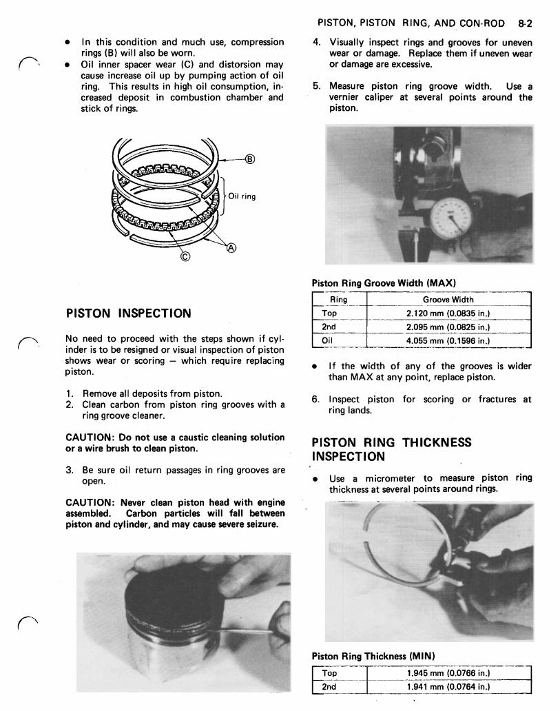
PISTON, PISTON RING, AND CON-ROD 8-2
4. Visually inspect rings and grooves for uneven wear or damage. Replace them if uneven wear or damage are excessive.
In this condition and much use, compression rings (B) will also be worn. Oil inner spacer wear (C) and distorsion may cause increase oil up by pumping action of oil ring. This results in high oil consumption, in- creased deposit in combustion chamber and stick of rings.
5. Measure piston ring groove width. Use a vernier caliper a t several points around the piston.
ring
Piston Ring Groove Width (MAX)
PISTON INSPECTION
No need to proceed with the steps shown if cyl- inder is to be resigned or visual inspection of piston shows wear or scoring - which require replacing piston.
1. Remove all deposits from piston. 2. Clean carbon from piston ring grooves with a
ring groove cleaner.
CAUTION: Do not use a caustic cleaning solution or a wire brush to clean piston.
3. Be sure oil return passages in ring grooves are open.
CAUTION: Never clean piston head with engine assembled. Carbon particles will fall between piston and cylinder, and may cause severe seizure.
Ring Groove Width I Top I 2.120 rnm (0.0835 in.) I
2.095 mm (0.0825 in.)
4.055 rnm (0.1596 in.) --_-
I f the width of any of the grooves is wider than MAX at any point, replace piston.
6. Inspect piston for scoring or fractures a t ring lands.
PISTON RING THICKNESS INSPECTION
Use a micrometer to measure piston ring thickness a t several points around rings.
Piston Ring Thickness (MIN)
1.945 mm (0.0766 in.)
1.941 mm (0.0764 in.)
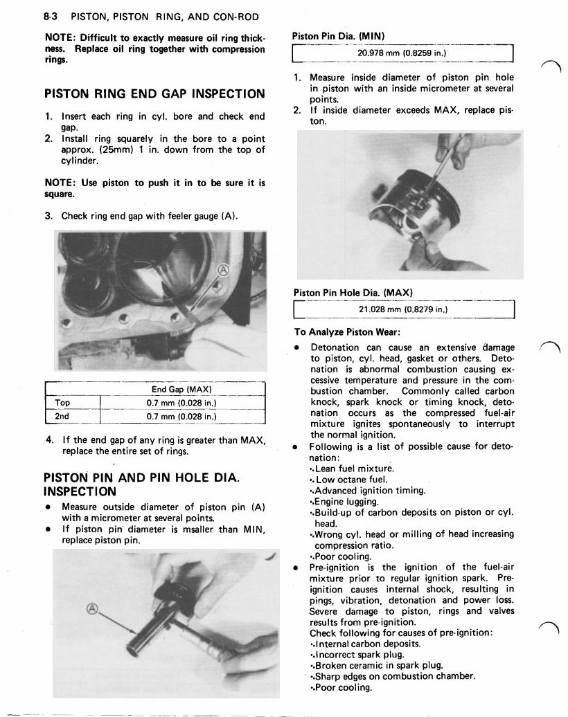
8-3 PISTON, PISTON RING, AND CON-ROD
NOTE: Difficult to exactly measure oil ring thick- ness. Replace oil ring together with compression rings.
PISTON RING END GAP INSPECTION
1. Insert each ring in cyl. bore and check end gap.
2. Install ring squarely in the bore to a point approx. (25mm) 1 in. down from the top of cylinder.
NOTE: Use piston to push it in to be sure it is square.
3. Check ring end gap with feeler gauge (A).
End Gap (MAX)
0.7 mm (0.028 in.)
0.7 mm (0.028 in.)
4. I f the end gap of any ring is greater than MAX, replace the entire set of rings.
PISTON PIN AND PIN HOLE DIA. INSPECTION
Measure outside diameter of piston pin (A)
I f piston pin diameter is msaller than MIN, with a micrometer a t several points.
replace piston pin.
Piston Pin Dia. (MIN)
20.978 mm (0.8259 in.)
1. Measure inside diameter of piston pin hole in piston with an inside micrometer at several points.
2. I f inside diameter exceeds MAX, replace pis- ton.
I
Piston Pin Hole Dia. (MAX)
21.028 mm (0.8279 in.) I To Analyze Piston Wear:
Detonation can cause an extensive damage to piston, cyl. head, gasket or others. Deto- nation is abnormal combustion causing ex- cessive temperature and pressure in the com- bustion chamber. Commonly called carbon knock, spark knock or timing knock, deto- nation occurs as the compressed fuel-air mixture ignites spontaneously to interrupt the normal ignition. Following is a l ist of possible cause for deto- nation:
Lean fuel mixture. Low octane fuel. Advanced ignition timing. Engine lugging. Build-up of carbon deposits on piston or cyl.
Wrong cyl. head or milling of head increasing
Poor cooling. Pre-ignition is the ignition of the fuel-air mixture prior to regular ignition spark. Pre- ignition causes internal shock, resulting in pings, vibration, detonation and power loss. .Severe damage to piston, rings and valves results from pre-ignition. Check following for causes of pre-ignition:
Internal carbon deposits. Incorrect spark plug. Broken ceramic in spark plug. Sharp edges on combustion chamber. Poor cooling.
head.
compression ratio.
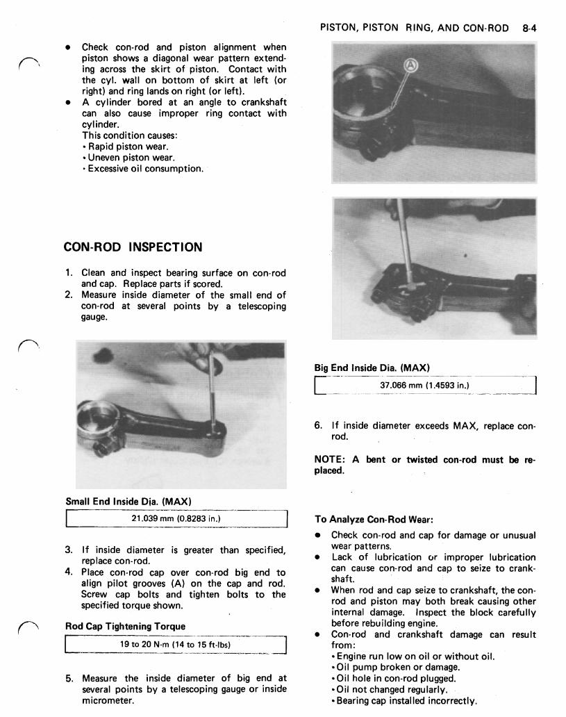
PISTON, PISTON RING, AND CON-ROD 8-4
Check con-rod and piston alignment when piston shows a diagonal wear pattern extend- ing across the skirt of piston. Contact with the cyl. wall on bottom of skirt a t left (or right) and ring lands on right (or left). A cylinder bored a t an angle to crankshaft can also cause improper ring contact with cylinder. This condition causes:
Rapid piston wear. Uneven piston wear. Excessive oil consumption.
CON-ROD INSPECTION
1. Clean and inspect bearing surface on con-rod and cap. Replace parts if scored.
2. Measure inside diameter of the small end of con-rod a t several points by a telescoping gauge.
Big End Inside Dia. (MAX)
37.066 mm (1.4593 in.)
6. If inside diameter exceeds MAX, replace con- rod.
NOTE: A bent or twisted con-rod must be re- placed.
Small End Inside Dia. (MAX)
I 21.039 mm (0.8283 in.)
3. If inside diameter is greater than specified, replace con-rod.
4. Place con-rod cap over con-rod big end to align pilot grooves (A) on the cap and rod. Screw cap bolts and tighten bolts to the specified torque shown.
Rod Cap Tightening Torque
19 to 20 N-m (14 to 15 ft-lbs) --I--
----_____
5. Measure the inside diameter of big end a t several points by a telescoping gauge or inside micrometer.
To Analyze Con-Rod Wear:
Check con-rod and cap for damage or unusual wear patterns. Lack of lubrication or improper lubrication can cause con-rod and cap to seize to crank- shaft. When rod and cap seize to crankshaft, the con- rod and piston may both break causing other internal damage. Inspect the block carefully before rebuilding engine. Con-rod and crankshaft damage can result from:
Engine run low on oil or without oil. Oil pump broken or damage. Oil hole in con-rod plugged. Oil not changed regularly. Bearing cap installed incorrectly.
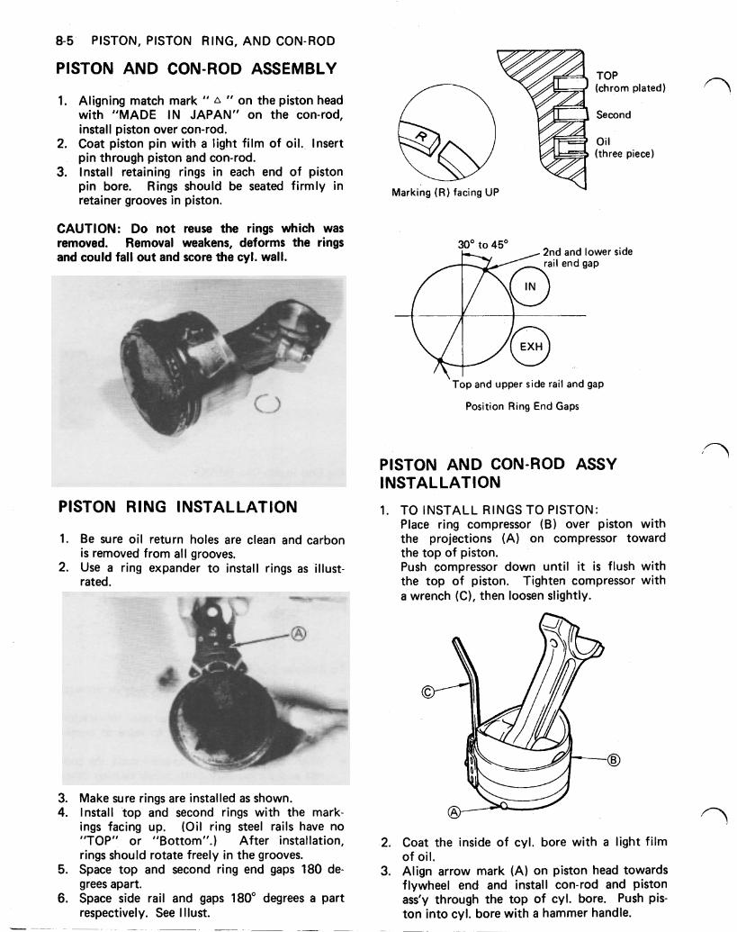
8-5 PISTON, PISTON RING, AND CON-ROD
PISTON AND CON-ROD ASSEMBLY
1. Aligning match mark " " on the piston head with "MADE IN JAPAN" on the con-rod, install piston over con-rod.
2. Coat piston pin with a light film of oil. Insert pin through piston and con-rod.
3. Install retaining rings in each end of piston pin bore. Rings should be seated firmly in retainer grooves in piston.
CAUTION: Do not reuse the rings which was removed. Removal weakens, deforms the rings and could fall out and score the cyl. wall.
PISTON RING INSTALLATION
1.
2.
3. 4.
5.
6.
Be sure oil return holes are clean and carbon is removed from all grooves. Use a ring expander to install rings as illust- rated.
Make sure rings are installed as shown. Install top and second rings with the mark- ings facing up. (Oil ring steel rails have no "TOP" or "Bottom".) After installation, rings should rotate freely in the grooves. Space top and second ring end gaps 180 de- grees apart. Space side rail and gaps 180° degrees a part respectively. See I Ilust.
Marking ( R ) facing UP
TOP (chrom plated)
Second
Oil (three piece)
30' to 45' 2nd and lower side
Top and upper side rail and gap
Position Ring End Gaps
PISTON AND CON-ROD ASSY INSTALLATION
1.
2.
3.
TO INSTALL RINGS TO PISTON: Place ring compressor (B) over piston with the projections (A) on compressor toward the top of piston. Push compressor down until it is flush with the top of piston. Tighten compressor with a wrench (C), then loosen slightly.
Coat the inside of cyl. bore with a light film of oil. Align arrow mark (A) on piston head towards flywheel end and install con-rod and piston ass'y through the top of cyl. bore. Push pis- ton into cyl. bore with a hammer handle.
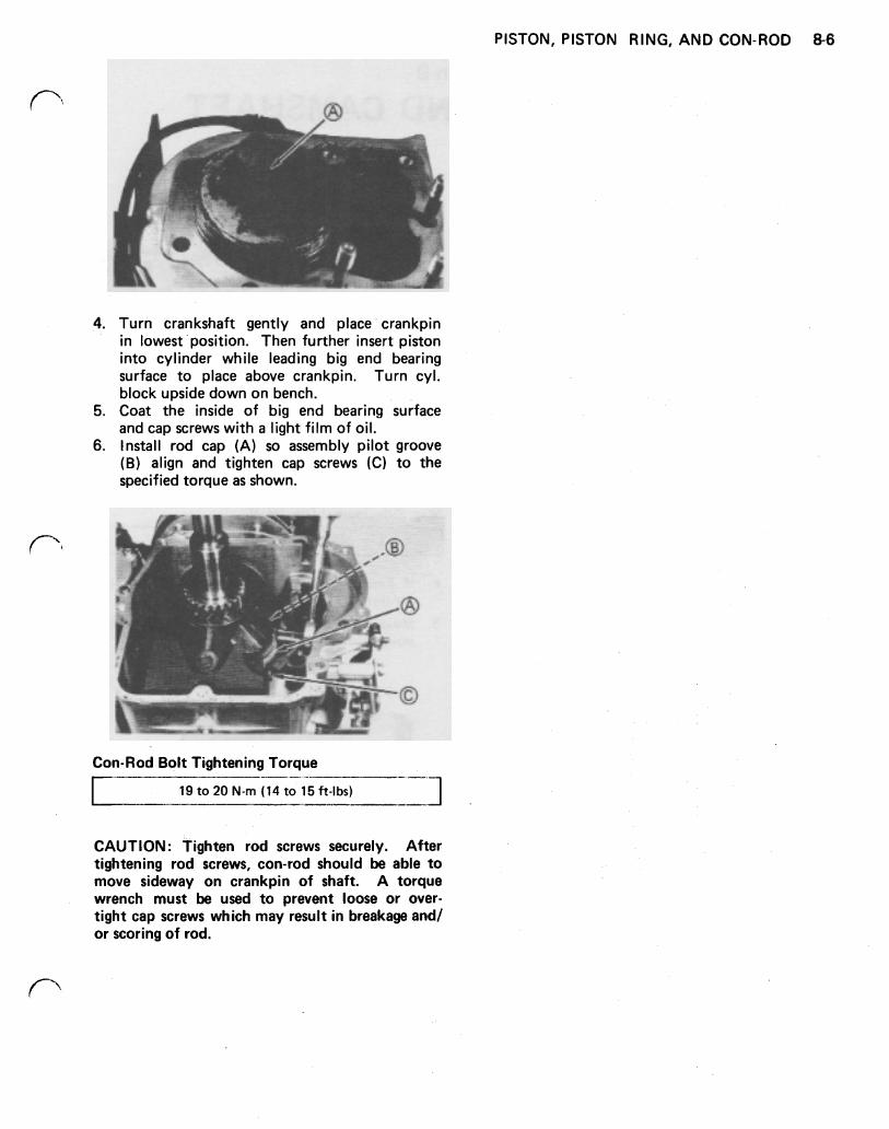
PISTON, PISTON RING, AND CON-ROD 8-6
4. Turn crankshaft gently and place crankpin in lowest position. Then further insert piston into cylinder while leading big end bearing surface to place above crankpin. Turn cyl. block upside down on bench.
5. Coat the inside of big end bearing surface and cap screws with a light film of oil.
6. Install rod cap (A) so assembly pilot groove (B) align and tighten cap screws (C) to the specified torque as shown.
Con-Rod Bolt Tightening Torque
r 19 to 20 N-m (14 to 15 ft-lbs)
CAUTION: Tighten rod screws securely. After tightening rod screws, con-rod should be able to move sideway on crankpin of shaft. A torque wrench must be used to prevent loose or over- tight cap screws which may result in breakage and/ or scoring of rod.
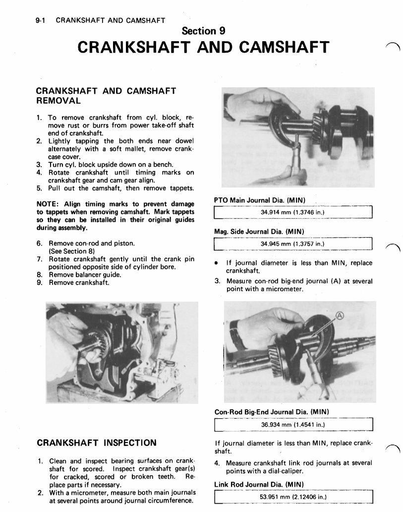
9-1 CRANKSHAFT AND CAMSHAFT
Section 9
CRANKSHAFT AND CAMSHAFT
CRANKSHAFT AND CAMSHAFT REMOVAL
1. To remove crankshaft from cyl. block, re- move rust or burrs from power take-off shaft end of crankshaft.
2. Lightly tapping the both ends near dowel alternately with a soft mallet, remove crank- case cover.
3. Turn cyl. block upside down on a bench. 4. Rotate crankshaft until timing marks on
5. Pull out the camshaft, then remove tappets. crankshaft gear and cam gear align.
NOTE: Align timing marks to prevent damage to tappets when removing camshaft. Mark tappets so they can be installed in their original guides during assembly.
PTO Main Journal Dia. (MIN)
mm (1.3746
Mag. Side Journal Dia. (MIN)
6. Remove con-rod and piston.
7. Rotate crankshaft gently until the crank pin
8. Remove balancer guide. 9. Remove crankshaft.
(See Section 8 )
positioned opposite side of cylinder bore.
34.945 mm (1.3757 in.)
I f journal diameter is less than MIN, replace
3. Measure con-rod big-end journal (A) a t several crankshaft.
point with a micrometer.
Con-Rod Big-End Journal Dia. (MIN)
36.934 mm (1.4541 in.)
CRANKSHAFT INSPECTION I f journal diameter is less than MIN, replace crank- shaft.
1. and inspect bearing surfaces On crank- 4. Measure crankshaft link rod journals a t several shaft for scored. Inspect crankshaft gear(s) points with a dial-caliper. for cracked, scored or broken teeth. Re- place parts if necessary. Link Rod Journal Dia. (MIN)
2. With a micrometer, measure both main journals a t several points around journal circumference. 53.951 mm (2.12406 in.)
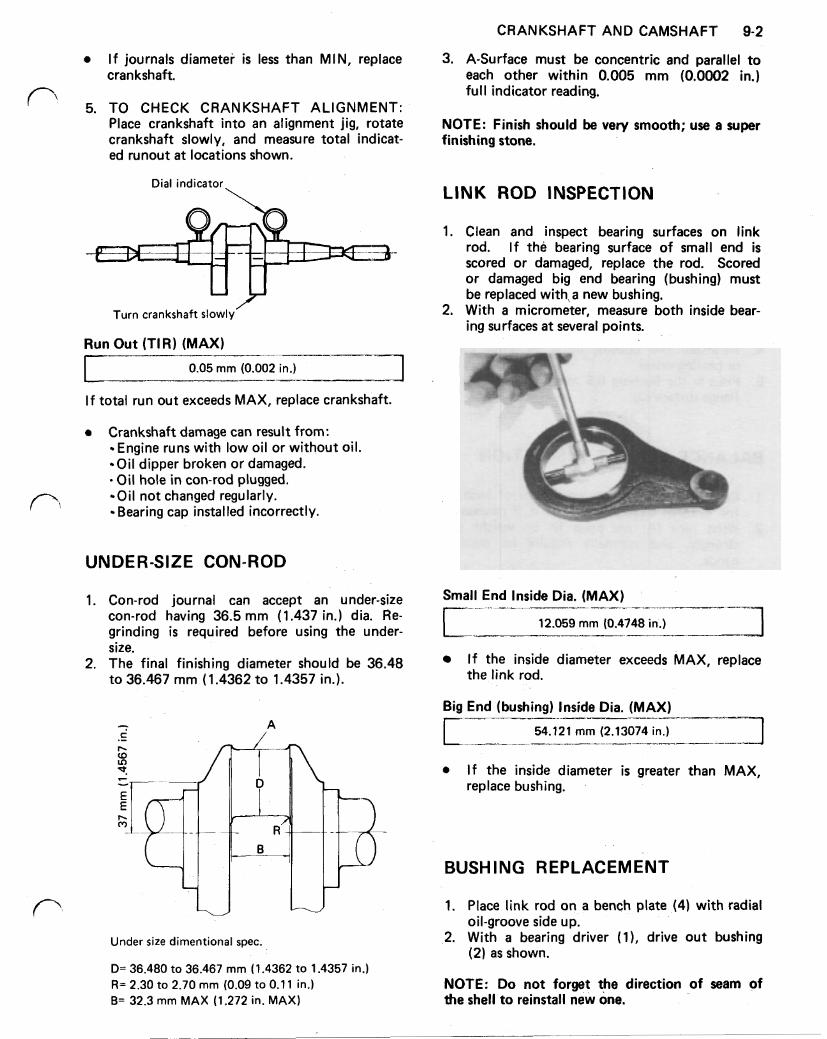
CRANKSHAFT AND CAMSHAFT 9-2
3. A-Surface must be concentric and parallel to each other within 0.005 mm (0.0002 in.) full indicator reading.
I f journals diameter is less than MIN, replace crankshaft.
5. TO CHECK CRANKSHAFT ALIGNMENT: Place crankshaft into an alignment jig, rotate crankshaft slowly, and measure total indicat- ed runout a t locations shown.
Dial indicator \
Turn crankshaft slowly
Run Out (TIR) (MAX)
0.05 mm (0.002 in.)
If total run out exceeds MAX, replace crankshaft.
e Crankshaft damage can result from: Engine runs with low oil or without oil. Oil dipper broken or damaged. Oil hole in con-rod plugged. Oil not changed regularly. Bearing cap installed incorrectly.
UNDER-SIZE CON-ROD
1. Con-rod journal can accept an under-size con-rod having 36.5 mm (1.437 in.) dia. Re- grinding is required before using the under- size.
2. The final finishing diameter should be 36.48 to 36.467 mm (1.4362 to 1.4357 in.).
c I-
R B
Under size dimentional spec.
D= 36.480 to 36.467 mm (1.4362 to 1.4357 in.) R= 2.30 to 2.70 mm (0.09 to 0.1 1 in.) B= 32.3 mm MAX (1.272 in. MAX)
NOTE: Finish should be very smooth; use a super finishing stone.
LINK ROD INSPECTION
1. Clean and inspect bearing surfaces on link rod. I f the bearing surface of small end is scored or damaged, replace the rod. Scored or damaged big end bearing (bushing) must be replaced with a new bushing.
2. With a micrometer, measure both inside bear- ing surfaces a t several points.
Small End Inside Dia. (MAX)
12.059 mm (0.4748 in.)
I f the inside diameter exceeds MAX, replace the link rod.
Big End (bushing) Inside Dia. (MAX)
r 54.121 mm (2.13074 in.)
If the inside diameter is greater than MAX, replace bushing.
BUSHING REPLACEMENT
1. Place link rod on a bench plate (4) with radial
2. With a bearing driver (1), drive out bushing oil-groove side up.
(2) as shown.
NOTE: Do not forget the direction of seam of the shell to reinstall new one.
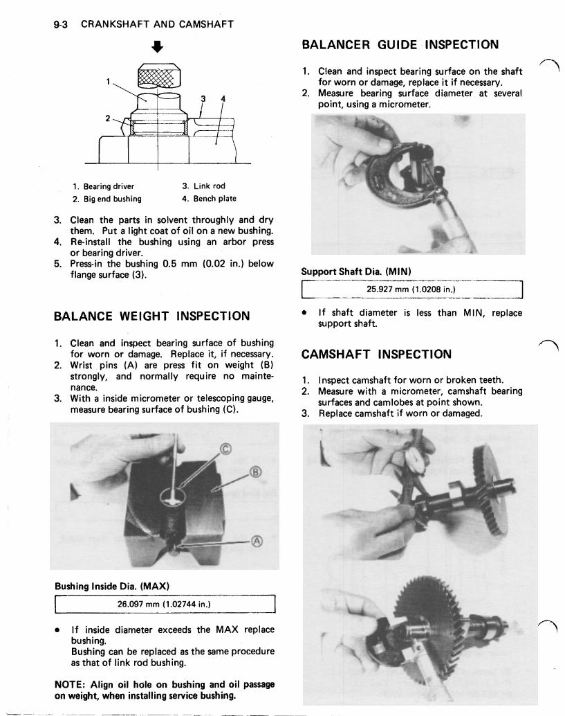
9-3 CRANKSHAFT AND CAMSHAFT
BALANCER GUIDE -INSPECTION
1. Clean and inspect bearing surface on the shaft for worn or damage, replace it if necessary.
2. Measure bearing surface diameter a t several point, using a micrometer.
1. Bearing driver 3. Link rod 2. Big end bushing 4. Bench plate
3. Clean the parts in solvent throughly and dry them. Put a light coat of oil on a new bushing.
4. Re-install the bushing using an arbor press or bearing driver.
5. Press-in the bushing 0.5 mm (0.02 in.) below flange surface (3).
BALANCE WEIGHT INSPECTION
1. Clean and inspect bearing surface of bushing for worn or damage. Replace it, if necessary.
2. Wrist pins (A) are press f i t on weight (B) strongly, and normally require no mainte- nance.
3. With a inside micrometer or telescoping gauge, measure bearing surface of bushing (C).
Bushing Inside Dia. (MAX)
26.097 mm (1.02744 in.)
I f inside diameter exceeds the MAX replace bushing. Bushing can be replaced as the same procedure as that of link rod bushing.
NOTE: Align oil hole on bushing and oil passage on weight, when installing service bushing.
Support Shaft Dia. (MIN)
I 25.927 mm (1.0208 in.) I I f shaft diameter is less than MIN, replace support shaft.
CAMSHAFT INSPECTION
1. Inspect camshaft for worn or broken teeth. 2. Measure with a micrometer, camshaft bearing
surfaces and camlobes a t point shown. 3. Replace camshaft if worn or damaged.
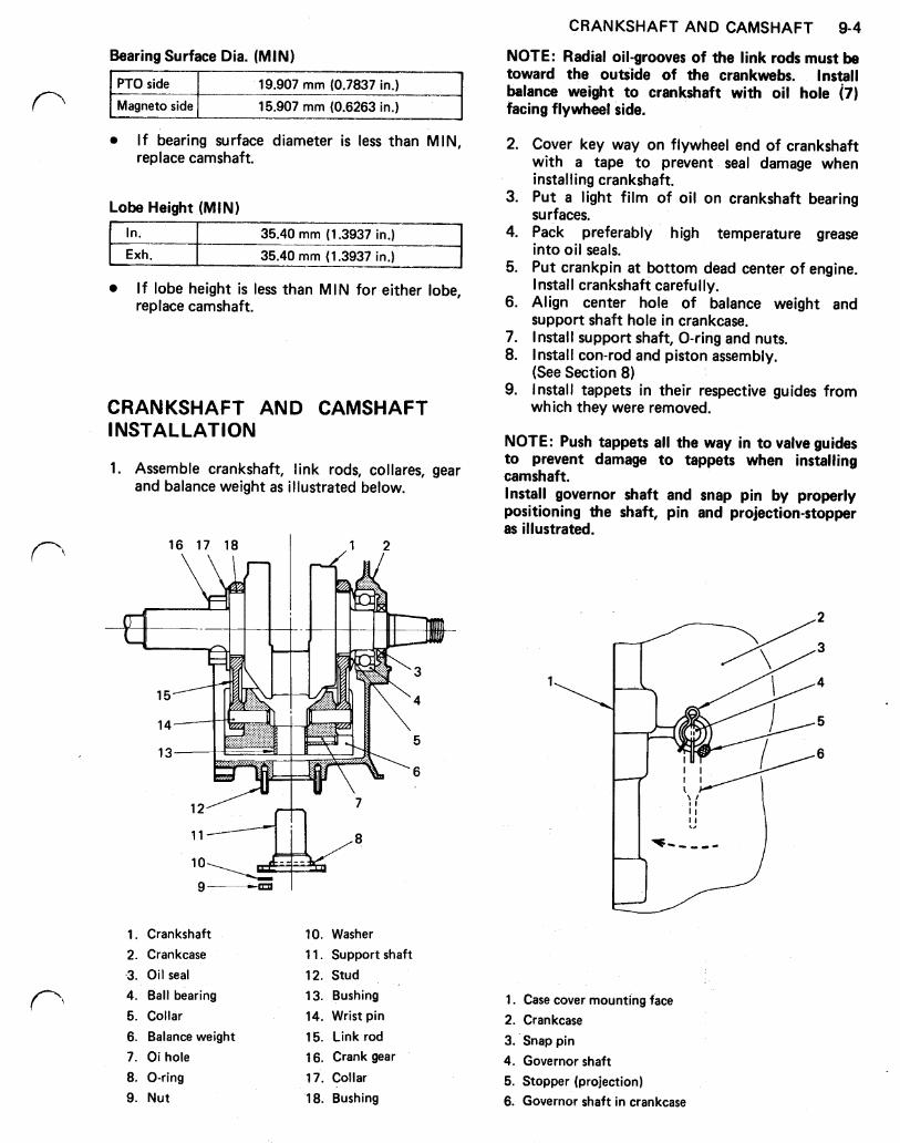
CRANKSHAFT AND CAMSHAFT 9-4
NOTE: Radial oil-grooves of the link rods must be toward the outside of the crankwebs. Install balance weight to crankshaft with oil hole (7) facing flywheel side.
Bearing Surface Dia. (MIN)
If bearing surface diameter is less than MIN, replace camshaft.
Lobe Height (MIN)
If lobe height is less than MIN for either lobe, replace camshaft.
CRANKSHAFT AND CAMSHAFT INSTALLATION
1. Assemble crankshaft, link rods, collares, gear and balance weight as illustrated below.
16 17 18 I
7
8
1. Crankshaft 2. Crankcase 3. Oil seal
10. Washer 11. Support shaft 12. Stud
4. Ball bearing 13. Bushing 5. Collar 14. Wrist pin 6. Balance weight 15. Link rod 7. Oi hole 16. Crank gear 8. O-ring 9. Nut
17. Collar 18. Bushing
2. Cover key way on flywheel end of crankshaft with a tape to prevent seal damage when installing crankshaft.
3. Put a light film of oil on crankshaft bearing surfaces.
4. Pack preferably high temperature grease into oil seals.
5. Put crankpin a t bottom dead center of engine. Install crankshaft carefully.
6. Align center hole of balance weight and support shaft hole in crankcase.
7. Install support shaft, O-ring and nuts. 8. Install con-rod and piston assembly.
9. Install tappets in their respective guides from (See Section 8)
which they were removed.
NOTE: Push tappets all the way in to valve guides to prevent damage to tappets when installing camshaft. Install governor shaft and snap pin by properly positioning the shaft, pin and projection-stopper as illustrated.
1. Case cover mounting face 2. Crankcase 3. Snap pin 4. Governor shaft 5. Stopper (projection) 6. Governor shaft in crankcase
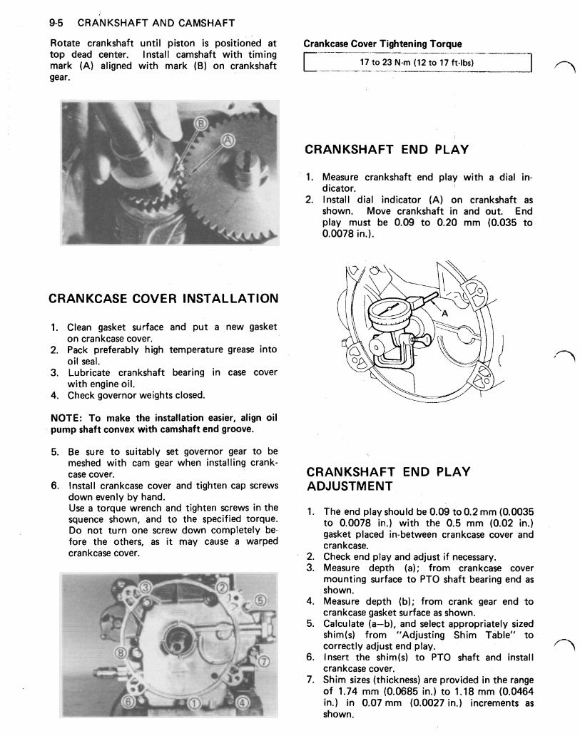
9-5 CRANKSHAFT AND CAMSHAFT
Rotate crankshaft until piston is positioned a t Crankcase Cover Tightening Torque top dead center. Install camshaft with timing mark (A) aligned with mark (B) on crankshaft 17 to 23 N-m (12 to 17 ft-lbs) gear.
CRANKCASE COVER INSTALLATION
1. Clean gasket surface and put a new gasket
2. Pack preferably high temperature grease into
3. Lubricate crankshaft bearing in case cover
4. Check governor weights closed.
on crankcase cover.
oil seal.
with engine oil.
NOTE: To make the installation easier, align oil pump shaft convex with camshaft end groove.
5. Be sure to suitably set governor gear to be meshed with cam gear when installing crank- case cover.
6. Install crankcase cover and tighten cap screws down evenly by hand. Use a torque wrench and tighten screws in the squence shown, and to the specified torque. Do not turn one screw down completely be- fore the others, as it may cause a warped crankcase cover.
CRANKSHAFT END PLAY
1. Measure crankshaft end play with a dial in- dicator.
2. Install dial indicator (A) on crankshaft as shown. Move crankshaft in and out. End play must be 0.09 to 0.20 mm (0.035 to 0.0078 in.).
CRANKSHAFT END PLAY ADJUSTMENT
1. The end play should be 0.09 to 0.2 mm (0.0035 to 0.0078 in.) with the 0.5 mm (0.02 in.) gasket placed in-between crankcase cover and crankcase.
2. Check end play and adjust if necessary. 3. Measure depth (a); from crankcase cover
mounting surface to PTO shaft bearing end as shown.
4. Measure depth (b); from crank gear end to crankcase gasket surface as shown.
5. Calculate (a-b), and select appropriately sized shim(s) from "Adjusting Shim Table" to correctly adjust end play.
6. Insert the shim(s) to PTO shaft and install crankcase cover.
7. Shim sizes (thickness) are provided in the range of 1.74 mm (0.0685 in.) to 1.18 mm (0.0464 in.) in 0.07 mm (0.0027 in.) increments as shown.
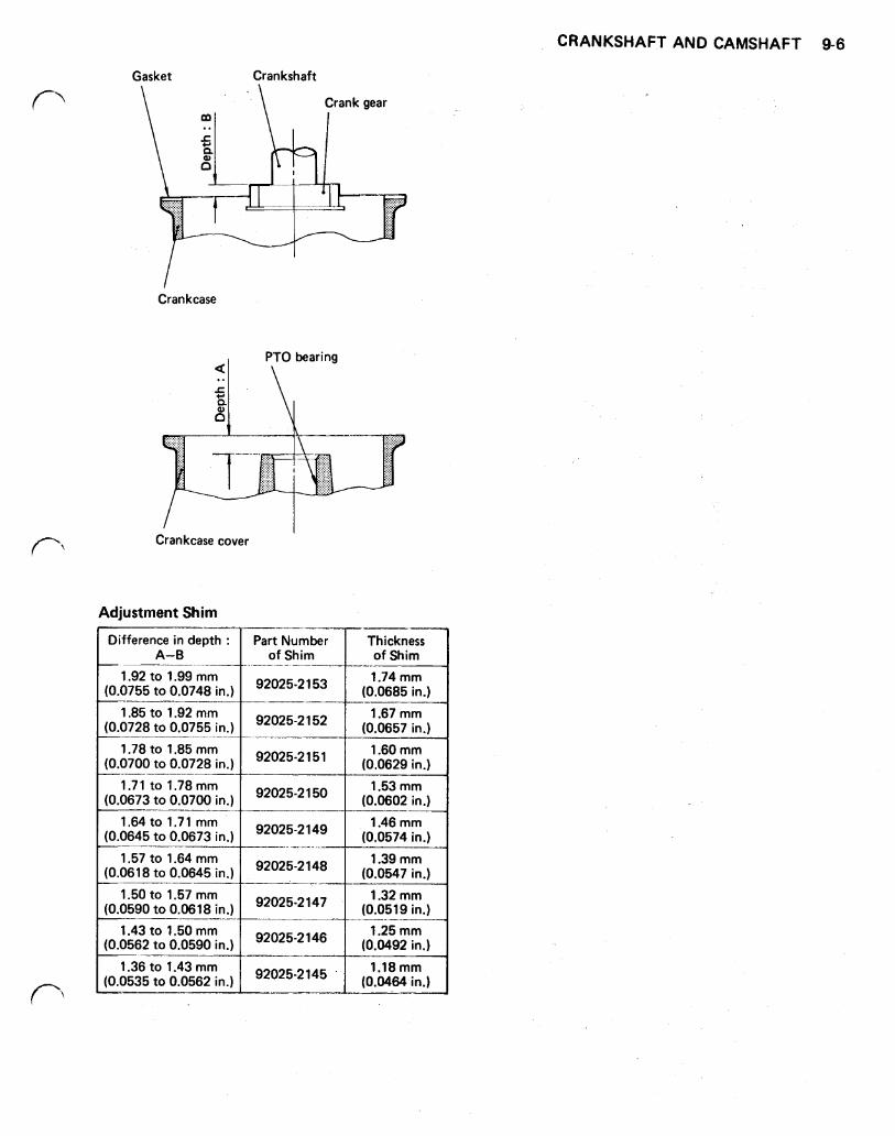
Gasket Crankshaft
Crankcase
bearing
Crankcase cover
Adjustment Shim
Difference in depth :
1.92 to 1.99 mm (0.0755 to 0.0748 in.)
1.85 to 1.92 mm (0.0728 to 0.0755 in.)
1.78 to 1.85 mm (0.0700 to 0.0728 in.)
1.71 to 1.78 mm (0.0673 to 0.0700 in.)
1.64 to 1.7 mm (0.0645 to 0.0673 in.)
1.57 to 1.64 mm (0.0618 to 0.0645 in.)
1.50 to 1.57 mm (0.0590 to 0.0618 in.)
1.43 to 1.50 mm (0.0562 to 0.0590 in.)
1.36 to 1.43 mm (0.0535 to 0.0562 in.)
A-0
-___-_-
of Shim
92025-2153 (0.0685 in.)
1.74mm
92025-2152 (0.0657 in.)
1.67 mm
92025-2151 (0.0629 in.)
1.60 mm
92025-2 150
92025-2149
92025-2 148
92025-2 147
92025-2 146
92025-2145
1.53mm (0.0602 in.)
1.46 mm (0.0574 in.)
1.39 mm (0.0547 in.)
1.32 mm (0.0519 in.)
1.25 mm (0.0492 in.)
1.18 mm (0.0464 in.)
CRANKSHAFT AND CAMSHAFT 9-6
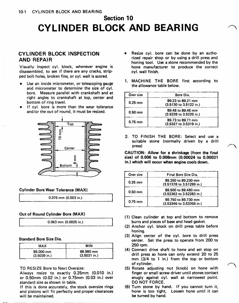
10-1 CYLINDER BLOCK AND BEARING
Section 10
CYLINDER BLOCK AND BEARING
CYLINDER BLOCK INSPECTION AND REPAl R Visually inspect cyl. block, whenever engine is disassembled, to see i f there are any cracks, strip- ped bolt holes, broken fins, or cyl. wall is scored.
Use an inside micrometer, or telescoping gauge and micrometer to determine the size of cyl. bore. Measure parallel with crankshaft and a t right angles to crankshaft a t top, center and bottom of ring travel. I f cyl. bore is more than the wear tolerance and/or the out of round, it must be resized.
Cylinder Bore Wear Tolerance (MAX)
0.076 mm (0.003 in.)
Out of Round Cylinder Bore (MAX)
0.063 mm (0.0025 in.) I I I
Standard Bore Size Dia.
MAX
(3.5031 in.) (3.5039 in.) 88.980 mm 89.000 mm
MIN
TO RESIZE Bore to Next Oversize: Always resize to exactly 0.25mm (0.010 in.) or 0.50mm (0.02 in.) or 0.75mm (0.03 in.) over standard size as shown in table. I f this is done accurately, the stock oversize rings and pistons will f i t perfectly and proper clearances will be maintained.
Resize cyl. bore can be done by an autho- rized repair shop or by using a drill press and honing tool. Use a stone recommended by the hone manufacturer to produce the correct cyl. wall finish.
1. MACHINE THE BORE first according to the allowance table below.
0.25 mm
0.50 mm
Bore Dia.
89.23 to 89.21 mm (3.5130 to 3.5122 in.)
89.48 to 89.46 mm (3.5228 to 3.5220 in.)
89.73 to 89.71 mm (3.5327 to 3.5319 in.)
2. TO FINISH THE BORE: Select and use a suitable stone (normally driven by a drill press)
CAUTION: Allow for a shrinkage (from the final size) of 0.006 to 0.008mm (0.00024 to 0.00031 in.) which will occur when engine cools down.
0.25 mm
0.75 mm
Final Bore Size Dia. I 89.250 to 89.230 mm
(3.51378 to 3.51299 in.)
89.500 to 89.480 mm (3.52362 to 3.52283 in.)
89.750 to 89.730 mm (3.53346 to 3.53268 in.)
(1) Clean cylinder a t top and bottom to remove burrs and pieces of base and head gasket.
(2) Anchor cyl. block on drill press table before honing.
(3) Align center of the cyl. bore to drill press center. Set the press to operate from 200 to 250 rpm.
(4) Connect drive shaft to hone and set stop on drill press so hone can only extend 20 to 25 mm (3/4 to 1 in.) from the top or bottom of cylinder.
(5) Rotate adjusting nut (knob) on hone with finger or small screw driver until stones contact snugly against cyl. wall a t narrowest point. DO NOT FORCE.
(6) Turn stone by hand. I f you cannot turn it, hone is too tight, Loosen hone until it can be turned by hand.
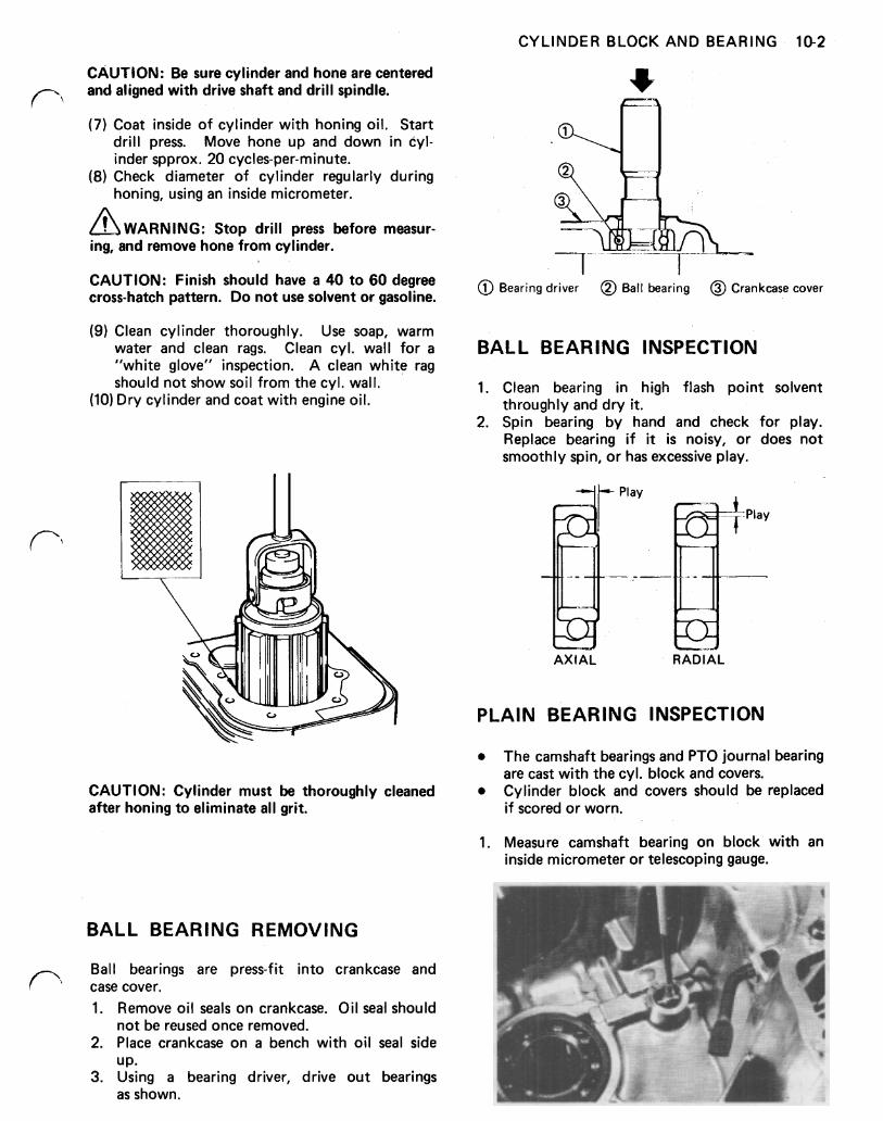
CYLINDER BLOCK AND BEARING 10-2
CAUTION: Be sure cylinder and hone are centered and aligned with drive shaft and drill spindle.
(7) Coat inside of cylinder with honing oil. Start drill press. Move hone up and down in cyl- inder spprox. 20 cycles-per-minute.
(8) Check diameter of cylinder regularly during honing, using an inside micrometer.
Stop drill press before measur- ing, and remove hone from cylinder.
CAUTION: Finish should have a 40 to 60 degree cross-hatch pattern. Do not use solvent or gasoline.
(9) Clean cylinder thoroughly. Use soap, warm water and clean rags. Clean cyl. wall for a "white glove" inspection. A clean white rag should not show soil from the cyl. wall.
(10) Dry cylinder and coat with engine oil.
CAUTION: Cylinder must be thoroughly cleaned after honing to eliminate all grit.
Bearing driver Ball bearing Crankcase cover
BALL BEARING INSPECTION
1. Clean bearing in high flash point solvent throughly and dry it.
2. Spin bearing by hand and check for play. Replace bearing if it is noisy, or does not smoothly spin, or has excessive play.
AXIAL RADIAL
PLAIN BEARING INSPECTION
The camshaft bearings and PTO journal bearing
Cylinder block and covers should be replaced are cast with the cyl. block and covers.
if scored or worn.
1. Measure camshaft bearing on block with an inside micrometer or telescoping gauge.
BALL BEARING REMOVING
Ball bearings are press-fit into crankcase and case cover. 1. Remove oil seals on crankcase. Oil seal should
2. Place crankcase on a bench with oil seal side
3. Using a bearing driver, drive out bearings
not be reused once removed.
UP.
as shown.
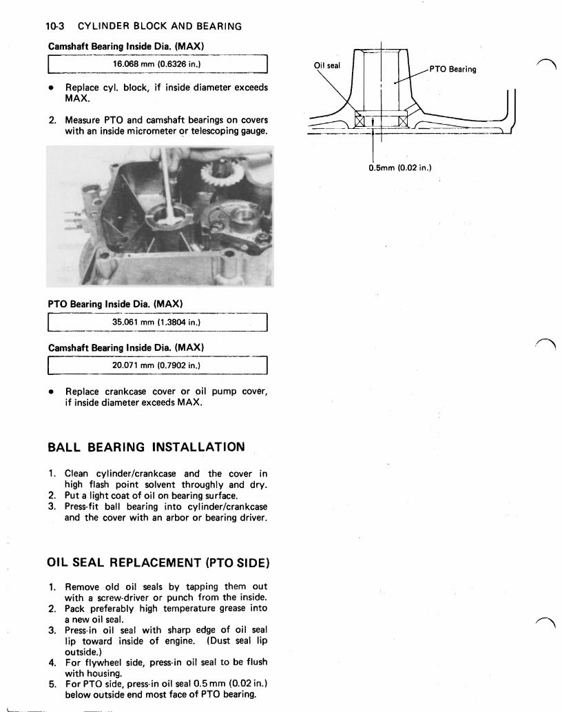
10-3 CYLINDER BLOCK AND BEARING
Camshaft Bearing Inside Dia. (MAX)
16.068 mm (0.6326 in.)
Replace cyl. block, if inside diameter exceeds MAX.
2. Measure PTO and camshaft bearings on covers with an inside micrometer or telescoping gauge.
PTO Bearing Inside Dia. (MAX)
mm (1.3804 in.)
Camshaft Bearing Inside Dia. (MAX)
I 20.071 mm (0.7902 in.) I Replace crankcase cover or oil pump cover, if inside diameter exceeds MAX.
BALL BEARING INSTALLATION
1. Clean cylinder/crankcase and the cover in high flash point solvent throughly and dry.
2. Put a light coat of oil on bearing surface. 3. Press-fit ball bearing into cyIinder/crankcase
and the cover with an arbor or bearing driver.
OIL SEAL REPLACEMENT (PTO SIDE)
1. Remove old oil seals by tapping them out with a screw-driver or punch from the inside.
2. Pack preferably high temperature grease into a new oil seal.
3. Press-in oil seal with sharp edge of oil seal lip toward inside of engine. (Dust seal lip outside.)
4. For flywheel side, press-in oil seal to be flush with housing.
5. For PTO side, press-in oil seal 0.5 mm (0.02 in.) below outside end most face of PTO bearing.
0.5mm (0.02 in.)
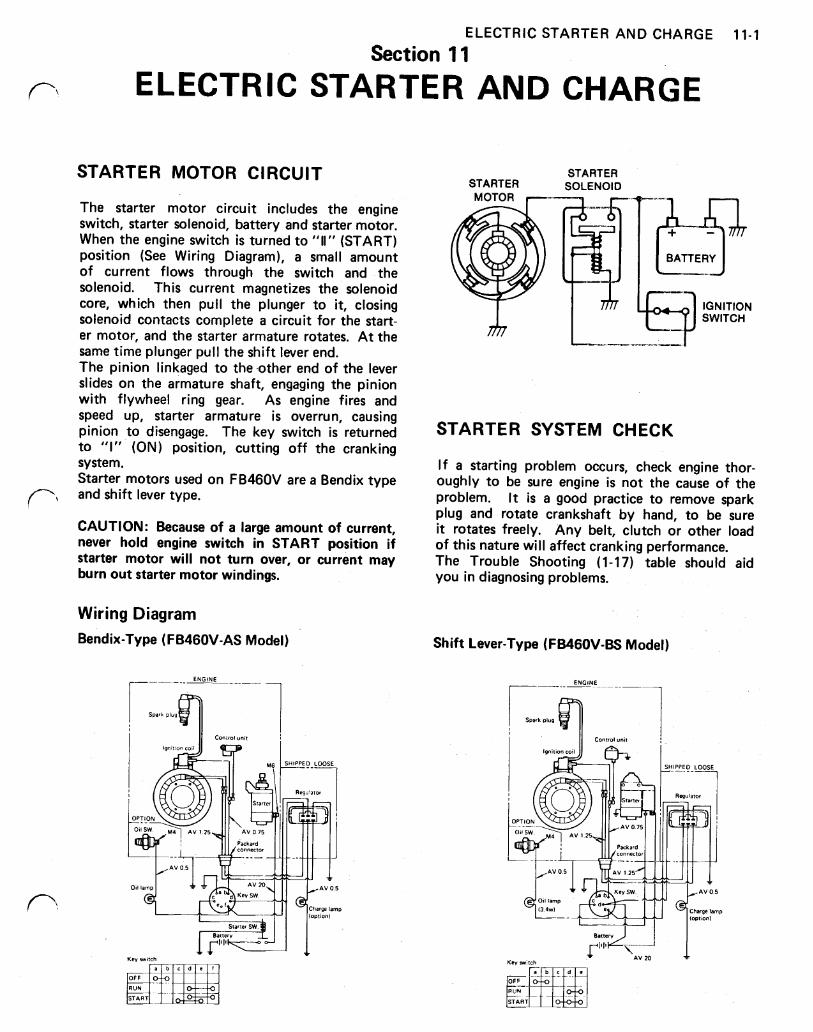
ELECTRIC STARTER AND CHARGE 11-1
Section 11 ELECTRIC STARTER AND CHARGE
STARTER MOTOR CIRCUIT
The starter motor circuit includes the engine switch, starter solenoid, battery and starter motor. When the engine switch is turned to (START) position (See Wiring Diagram), a small amount of current flows through the switch and the solenoid. This current magnetizes the solenoid core, which then pull the plunger to it, closing solenoid contacts complete a circuit for the start- er motor, and the starter armature rotates. At the same time plunger pull the shift lever end. The pinion linkaged to the other end of the lever slides on the armature shaft, engaging the pinion with flywheel ring gear. As engine fires and speed up, starter armature is overrun, causing pinion to disengage. The key switch is returned to "I" (ON) position, cutting off the cranking system. Starter motors used on FB46OV are a Bendix type and shift lever type.
CAUTION: Because of a large amount of current, never hold engine switch in START position if starter motor will not turn over, or current may burn out starter motor windings.
Wiring Diagram Bendix-Type (FB460V-AS Model)
ENGINE
STARTER STARTER
SOLENOID MOTOR
IGNITION SWITCH
STARTER SYSTEM CHECK
I f a starting problem occurs, check engine thor- oughly to be sure engine is not the cause of the problem. It is a good practice to remove spark plug and rotate crankshaft by hand, to be sure it rotates freely. Any belt, clutch or other load of this nature will affect cranking performance. The Trouble Shooting (1-1 7) table should aid you in diagnosing problems.
Shift Lever-Type (FB46OV-BS Model)
AV 20
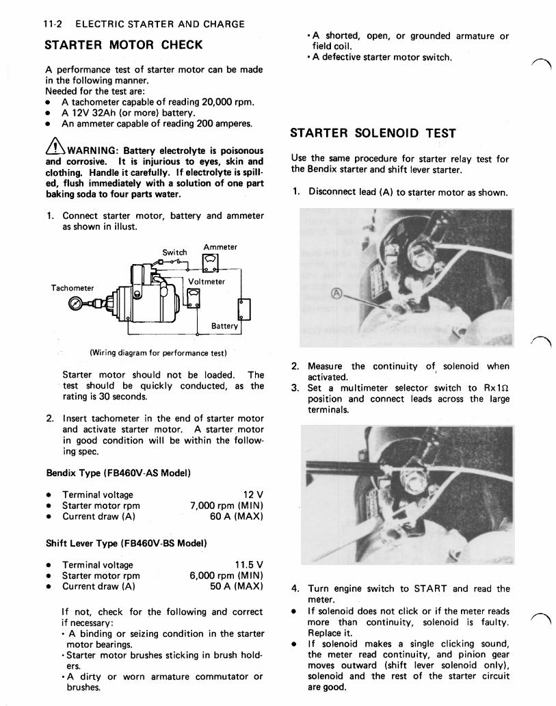
11-2 ELECTRIC STARTER AND CHARGE
STARTER MOTOR CHECK
A performance test of starter motor can be made in the following manner. Needed for the test are:
A tachometer capable of reading 20,000 rpm. A 12V 32Ah (or more) battery. An ammeter capable of reading 200 amperes.
WARNING: Battery electrolyte is poisonous and corrosive. It is injurious to eyes, skin and clothing. Handle it carefully. If electrolyte is spill- ed, flush immediately with a solution of one part baking soda to four parts water.
1. Connect starter motor, battery and ammeter as shown in illust.
A I
(Wiring diagram for performance test)
Starter motor should not be loaded. The test should be quickly conducted, as the rating is 30 seconds.
2. Insert tachometer in the end of starter motor and activate starter motor. A starter motor in good condition will be within the follow- ing spec.
Bendix Type (FB460V-AS Model)
Terminal voltage 12 v Starter motor rpm 7,000 rpm (MIN) Current draw (A) 60 A (MAX)
Shift Lever Type (FB46OV-BS Model)
Terminal voltage 11.5 V Starter motor rpm 6,000 rpm (MIN) Current draw (A) 50 A (MAX)
If not, check for the following and correct i f necessary:
A binding or seizing condition in the starter
'Starter motor brushes sticking in brush hold-
A dirty or worn armature commutator or
motor bearings.
ers.
brushes.
A shorted, open, or grounded armature or
A defective starter motor switch. field coil.
STARTER SOLENOID TEST
Use the same procedure for starter relay test for the Bendix starter and shift lever starter.
1.
2.
3.
4.
Disconnect lead (A) to starter motor as shown.
Measure the continuity of solenoid when activated. Set a multimeter selector switch to position and connect leads across the large terminals.
Turn engine switch to START and read the meter. I f solenoid does not click or if the meter reads more than continuity, solenoid is faulty. Replace it. If solenoid makes a single clicking sound, the meter read continuity, and pinion gear moves outward (shift lever solenoid only), solenoid and the rest of the starter circuit are good.
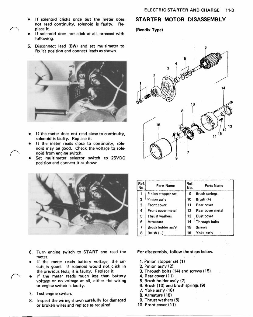
If solenoid clicks once but the meter does not read continuity, solenoid is faulty. Re-
I f solenoid does not click a t all, proceed with place it.
following.
5. Disconnect lead (BW) and set multimeter to position and connect leads as shown.
ELECTRIC STARTER AND CHARGE 11-3
STARTER MOTOR DISASSEMBLY
(Bendix Type)
2
I f the meter does not read close to continuity, solenoid is faulty. Replace it. I f the meter reads close to continuity, sole- noid may be good. Check the voltage to sole-
Set multimeter selector switch to 25VDC noid from engine switch.
position and connect it as shown.
Parts Name
6.
7. 8.
Turn engine switch to START and read the meter. I f the meter reads battery voltage, the cir- cuit, is good. If solenoid would not click in the previous tests, it is faulty. Replace it. I f the meter reads much less than battery voltage or no voltage at all, either the wiring or engine switch is faulty.
Test engine switch.
Inspect the wiring shown carefully for damaged or broken wires and replace as required.
1 2
Pinion stopper set
Brush (-) 8 Brush holder ass'y 7 Armature 6 Thrust washers 5 Front cover metal 4 Front cover 3 Pinion ass'y
Parts Name No.
For disassembly, follow the steps below.
1. Pinion stopper set (1 ) 2. Pinion ass'y (2) 3. Through bolts (14) and screws (1 5) 4. Rear cover ( 1 1 ) 5. Brush holder ass'y (7) 6. Brush (10) and brush springs (9) 7. Yoke ass'y (16) 8. Armature (16) 9. Thrust washers (5)
10. Front cover (11)
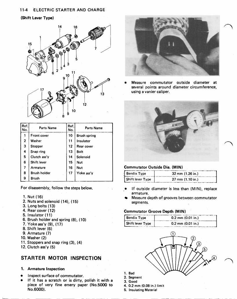
11-4 ELECTRIC STARTER AND CHARGE
(Shift Lever Type)
Measure commutator outside diameter a t several points around diameter circumference, using a vanier caliper.
Ref, No.
1 2 3 4 5 6 7 8 9
Parts Name
Front cover Washer
Stopper Snap ring Clutch ass'y
Shift lever Armature Brush holder Brush
Ref No.
10 11
12 13 14
15 16 17
Parts Name
Brush spring Insulator Rear cover Bolt Solenoid Nut Nut Yoke ass'y
For disassembly, follow the steps below.
1. Nut (16) 2. Nuts and solenoid (14), (15) 3. Long bolts (13) 4. Rear cover (1 2) 5. Insulator ( 1 1) 6. Brush holder and spring (8) , (10) 7. Yoke ass'y (9), (17) 8. Shift lever (6) 9. Armature (7)
10. Washer (2) 11. Stoppers and snap ring (3), (4) 12. Clutch ass'y (5)
STARTER MOTOR INSPECTION
1. Armature Inspection
Inspect surface of commutator. I f it has a scratch or is dirty, polish it with a piece of very fine emery paper (No.5000 to No.6000).
Commutator Outside Dia. (MIN) Bendix Type
I_--
32 mm (1.26 in.)
lever Type 27 mm (1.10 in.)
I f outside diameter is less than (MIN), replace
Measure depth of grooves between commutator armature.
segments.
Commutator Groove Depth (MIN) 0.2 mm (0.01 in.)
Shift lever Type 0.2 mm (0.01 in )
2. Segment 3. Good 4. 0.2 mm (0.08 in.) limit 5. Insulating Material
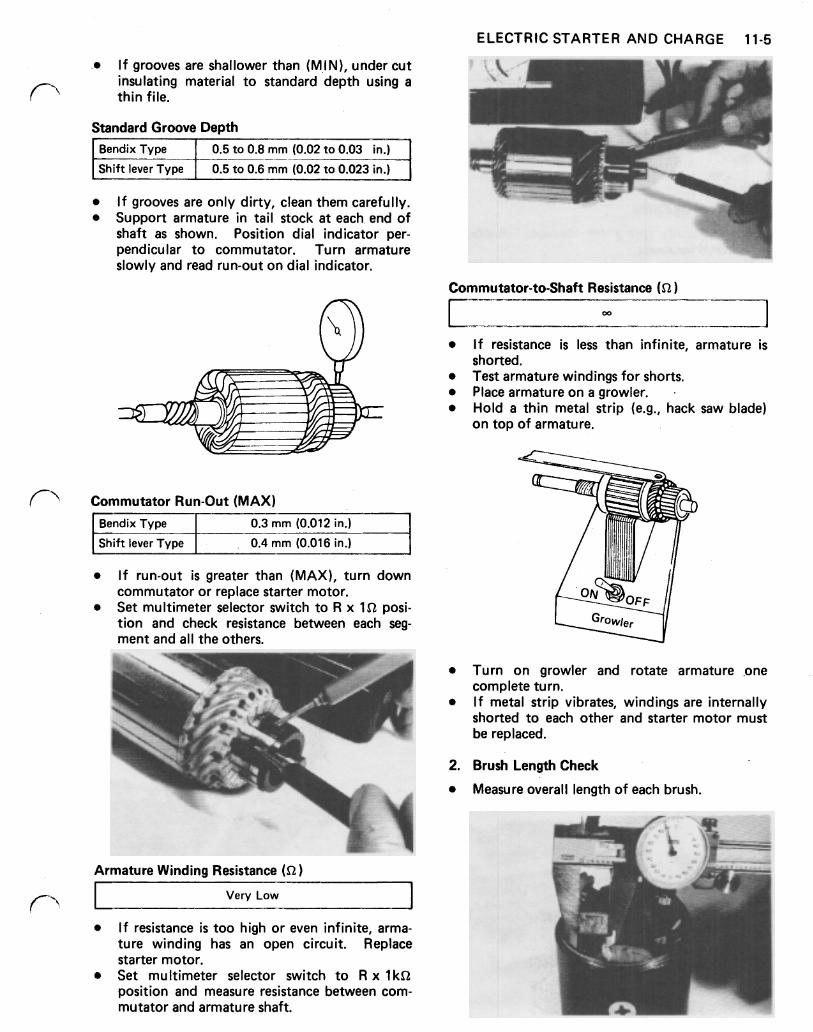
ELECTRIC STARTER AND CHARGE 11-5
I f grooves are shallower than (MIN), under cut insulating material to standard depth using a thin file.
Standard Groove Depth Bendix Type
Shift lever Type
0.5 to 0.8 mm (0.02 to 0.03 in.)
0.5 to 0.6mm (0.02 to 0.023 in.)
If grooves are only dirty, clean them carefully. Support armature in tail stock at each, end of shaft as shown. Position dial indicator per- pendicular to commutator. Turn armature slowly and read run-out on dial indicator.
Commutator Run-Out (MAX) Bendix Type 0.3 mm (0.012 in.) I Shift lever Type 0.4 mm (0.016 in.) I
Commutator-to-Shaft Resistance (52)
r
If run-out is greater than (MAX), turn down commutator or replace starter motor. Set multimeter selector switch to R x posi- tion and check resistance between each seg- ment and all the others.
2.
Armature Winding Resistance
Very Low
If resistance is less than infinite, armature is
Test armature windings for shorts. Place armature on a growler. Hold a thin metal strip (e.g., hack saw blade)
shorted.
on top of armature.
I f resistance is too high or even infinite, arma- ture winding has an open circuit. Replace starter motor. Set multimeter selector switch to R x position and measure resistance between com- mutator and armature shaft.
Turn on growler and rotate armature .one complete turn. I f metal strip vibrates, windings are internally shorted to each other and starter motor must be replaced.
Brush Length Check
Measure overall length of each brush.
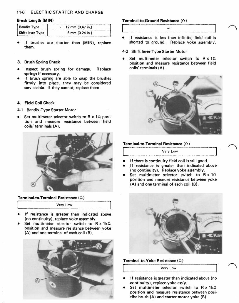
11-6 ELECTRIC STARTER AND CHARGE
Brush Length (M IN) Terminal-to-Ground Resistance
Shift lever Type 6 mm (0.24 in.) I f resistance is less than infinite. field coil is
3.
4.
4- 1
I f brushes are shorter than (MIN), replace shorted to ground. Replace yoke assembly. them.
4-2 Shift lever-Type Starter Motor
Set multimeter selector switch to R x Brush Spring Check position and measure resistance between field
Inspect brush spring for damage. Replace coils‘ terminals (A). springs if necessary. I f brush spring are able to snap the brushes firmly into place, they may be considered serviceable. If they cannot, replace them.
Field Coil Check
Bendix-Type Starter Motor
Set multimeter selector switch to R x posi- tion and measure resistance between field coils’ terminals (A).
Terminal-to-Terminal Resistance (52
Very Low
I f resistance is greater than indicated above (no continuity), replace yoke assembly. Set multimeter selector switch to R x 1 position and measure resistance between yoke (A) and one terminal of each coil (B).
Terminal-to-Terminal Resistance
Very Low
I f there is continuity field coil is still good. I f resistance is greater than indicated above (no continuity). Replace yoke assembly. Set multimeter selector switch to R x position and measure resistance between yoke (A) and one terminal of each coil (B).
Terminal-to-Yoke Resistance
I Very Low I I f resistance is greater than indicated above (no continuity), replace yoke ass‘y. Set multimeter selector switch to R x 1 position and measure resistance between posi- tibe brush (A) and starter motor yoke (B).
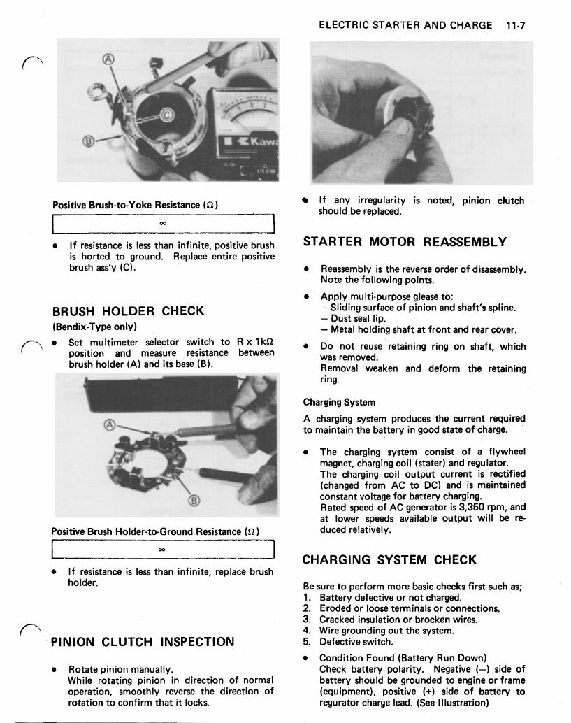
ELECTRIC STARTER AND CHARGE 11-7
Positive Brush-to-Yoke Resistance
I f resistance is less than infinite, positive brush is horted to ground. Replace entire positive brush ass’y (C).
BRUSH HOLDER CHECK (Bendix-Type only)
Set multimeter selector switch to R x 1 position and measure resistance between brush holder (A) and i ts base (B).
Positive Brush Holder-to-Ground Resistance )
I f resistance is less than infinite, replace brush holder.
PINION CLUTCH INSPECTION
Rotate pinion manually. While rotating pinion in direction of normal operation, smoothly reverse the direction of rotation to confirm that it locks.
I f any irregularity is noted, pinion clutch should be replaced.
STARTER MOTOR REASSEMBLY
Reassembly is the reverse order of disassembly. Note the following points.
Apply multi-purpose glease to: Sliding surface of pinion and shaft’s spline. Dust seal lip. Metal holding shaft a t front and rear cover.
Do not reuse retaining ring on shaft, which was removed. Removal weaken and deform the retaining ring.
Charging System
A charging system produces the current required to maintain the battery in good state of charge.
The charging system consist of a flywheel magnet, charging coil (stater) and regulator. The charging coil output current is rectified (changed from AC to DC) and is maintained constant voltage for battery charging. Rated speed of AC generator is 3,350 rpm, and a t lower speeds available output will be re- duced relatively.
CHARGING SYSTEM CHECK
Be sure to perform more basic checks first such as; 1. 2. 3. 4. 5.
Battery defective or not charged. Eroded or loose terminals or connections. Cracked insulation or brocken wires. Wire grounding out the system. Defective switch.
Condition Found (Battery Run Down) Check battery polarity. Negative (-) side of battery should be grounded to engine or frame (equipment), positive (+) side of battery to regurator charge lead. (See I Ilustration)
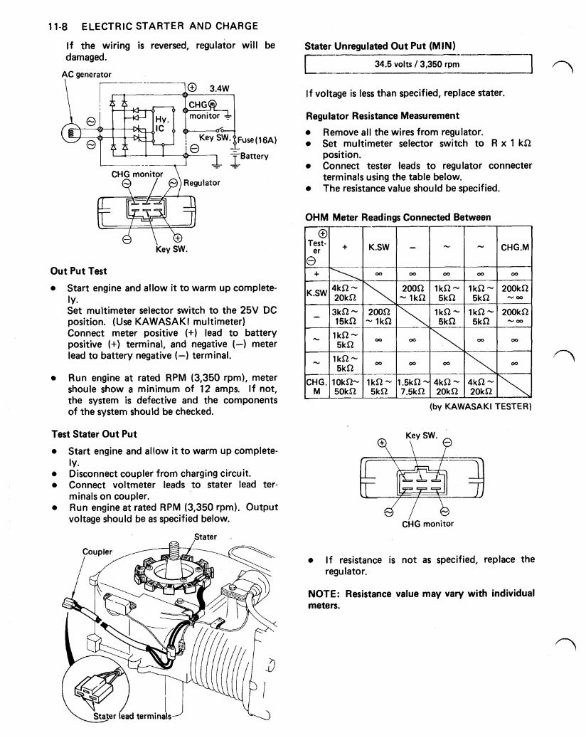
11-8 ELECTRIC STARTER AND CHARGE
I f the wiring is reversed, regulator will be damaged.
AC generator
3.4w
CHG monitor
d Key SW.
Out Put Test
Start engine and allow it to warm up complete- ly. Set multimeter selector switch to the 25V DC position. (Use KAWASAKI multimeter) Connect meter positive (+) lead to battery positive (+) terminal, and negative (-) meter lead to battery negative (-) terminal.
Run engine a t rated RPM (3,350 rpm), meter shoule show a minimum of 12 amps. If not, the system is defective and the components of the system should be checked.
Test Stater Out Put
Start engine and allow it to warm up complete-
Disconnect coupler from charging circuit. Connect voltmeter leads to stater lead ter-
Run engine a t rated RPM (3,350 rpm). Output
ly.
minals on coupler.
voltage should be as specified below.
Stater
Stater Unregulated Out Put (MIN)
34.5 volts 3,350 rpm
I f voltage is less than specified, replace stater.
Regulator Resistance Measurement
Remove all the wires from regulator. Set multimeter selector switch to R x 1
Connect tester leads to regulator connecter
The resistance value should be specified.
position.
terminals using the table below.
OHM Meter Readings Connected Between
(by KAWASAKI TESTER)
CHG monitor
I f resistance is not as specified, replace the regulator.
NOTE: Resistance value may vary with individual meters.
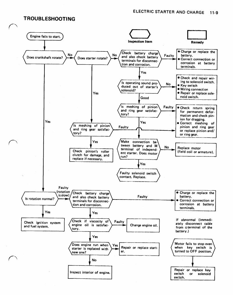
ELECTRIC STARTER AND CHARGE 11-9
TROUBLESHOOTING
Inspection Item Remedy
t Does crankshaft rotate? Does starter rotate?
terminals for
Faulty
Yes
Correct connection or
->- Is operating sound pro- duced out of starter’s
Check and repair wir- ing to solenoid switch.
Wiring connection Repair or replace sole- noid switch.
Check return spring for permanent defor- mation and check pin- ion for dragging. Correct meshing of pinion and ring gear
and ring gear satisfac- or replace pinion and/ or ring gear.
Faulty
I Yes /Make connection and No Replace motor
terminal of independ- Check pinion‘s ent starter. Does motor clutch for damage, and run? replace if necessary.
(field coil or armature).
I
Faulty solenoid switch
Faulty
(rotation Check battery charge Charge or replace the
terminals for disconnec- Correct connection or tion and corrosion, corrosion a t battery
Is rotation normal? is s low) and also check battery
terminals. Yes
If abnormal (Immedi- ately disconnect cable from of the battery.)
Check ignition system engine oil is satisfac- Change engine oil.
‘Motor fails to stop even starter is replaced with Repair or replace start- when key switch is new one? turned to OFF position.
t No I
Inspect interior of engine. I
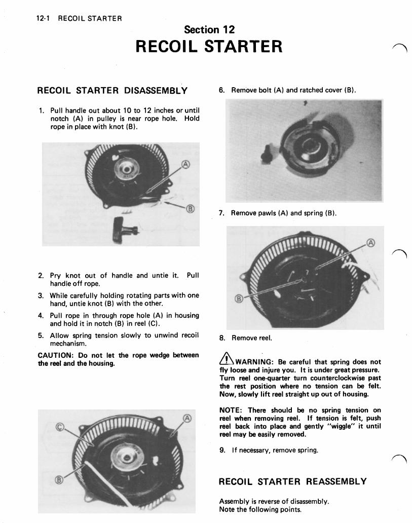
12-1 RECOIL STARTER
Section 12
RECOIL STARTER
RECOIL STARTER DISASSEMBLY 6. Remove bolt (A) and ratched cover (B).
1. Pull handle out about 10 to 12 inches or until notch (A) in pulley is near rope hole. Hold rope in place with knot (B).
7. Remove pawls (A) and spring (B).
2. Pry knot out of handle and untie it. Pull
3. While carefully holding rotating parts with one
4. Pull rope in through rope hole (A) in housing
5. Allow spring tension slowly to unwind recoil 8. Remove reel.
CAUTION: Do not let the rope wedge between the reel and the housing. Be careful that spring does not
fly loose and injure you. It is under great pressure. Turn reel one-quarter turn counterclockwise past the rest position where no tension can be felt. Now, slowly l i f t reel straight up out of housing.
handle off rope.
hand, untie knot (B) with the other.
and hold it in notch (B) in reel (C).
mechanism.
NOTE: There should be no spring tension on reel when removing reel. I f tension is felt, push reel back into place and gently "wiggle" it until reel may be easily removed.
9. If necessary, remove spring.
RECOIL STARTER REASSEMBLY
Assembly is reverse of disassembly. Note the following points.
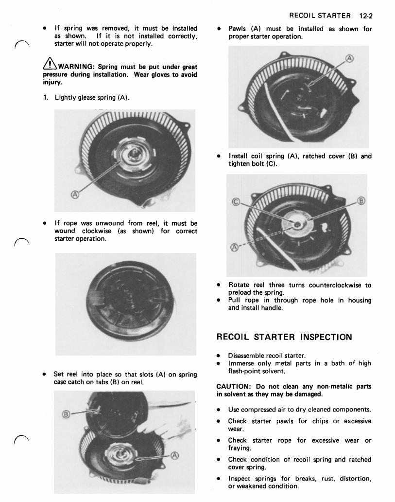
RECOIL STARTER 12-2
I f spring was removed, it must be installed Pawls (A) must be installed as shown for as shown. If it is not installed correctly, proper starter operation. starter will not operate properly.
//\WARNING: Spring must be put under great pressure during installation. Wear gloves to avoid injury.
1. Lightly glease spring (A).
Install coil spring (A), ratched cover (B) and tighten bolt (C).
I f rope was unwound from reel, it must be wound clockwise (as shown) for correct starter operation.
Rotate reel three turns counterclockwise to
Pull rope in through rope hole in housing preload the spring.
and install handle.
RECOIL STARTER INSPECTION
Disassemble recoil starter. Immerse only metal parts in a bath of high
Set reel into place so that slots (A) on spring flash-point solvent.
case catch on tabs (B) on reel. CAUTION: Do not clean any non-metalic parts in solvent as they may be damaged.
Use compressed air to dry cleaned components.
Check starter pawls for chips or excessive
Check starter rope for excessive wear or
Check condition of recoil spring and ratched
Inspect springs for breaks, rust, distortion,
wear.
fraying.
cover spring.
or weakened condition.