Katalog ADLER 10-2013 ENsml-group.ru/f/katalogklapanaadler-dietrichschwabe.pdf · (modified...
56
ADLER DIETRICH SCHWABE GESELLSCHAFT FÜR STEUER-REGEL-ARMATURENTECHNIK M.B.H.
Transcript of Katalog ADLER 10-2013 ENsml-group.ru/f/katalogklapanaadler-dietrichschwabe.pdf · (modified...
ADLER
DIETRICH SCHWABE GESELLSCHAFT FÜR STEUER-REGEL-ARMATURENTECHNIK M.B.H.


IND
EX
D. Schwabe GmbH ADLER Ball Valves Index 110912 Specification Subjects without prior notice
INDEX
Page
1
2
3
4
6
8
10
14
16
17
18
22
24
26
28
30
32
34
36
38
42
44
46
48
49
50
51
Descriptions
Index
Preposotion
Article-Code
Socket Ball Valve
Socket Ball Valve
Ball Valve, 3 pieces
Ball Valve, Wafer-Type
Ball Valve, Wafer-Type
Ball Valve, Wafer-Type with Heating Jacket
Ball Valve, Wafer-Type with Heating Jacket
Ball Valve, Wafer-Type
Ball Valve, Wafer-Type
Ball Valve, Wafer-Type
Ball Valve, Wafer-Type
Ball Valve, Wafer-Type
Ball Valve, Wafer-Type
Ball Valve, Wafer-Type
Ball Valve, 3-Way
Ball Valve, 3-Way
Ball Valve, 3-Way
Ball Valve, 4-Way
Socket Ball Valve, 3-Way
Socket Ball Valve, 4-Way
ADLER-Gear Box
Standard- and Special Device
Pressure-Temperature-Diagram
Flange Dimensions acc. to EN 1092
full
Passage
full
full
full
full
full
full
full
full
full
full
reduced
reduced
reduced
full
full
voll
full/reduced
full
full/reduced
T
FA1/F
RT7
ype
FP2
FS2
FP3
A2
FB1/FB2
FC1/FC2
FX1/FX2
FY1/FY2
FM2/FN2
FE2/FF2
FG2
FH2/FN2
VM2/VN2
VE27VF2
VG2
FU4
FV4
FZ4/FT4
FT5/VT5
FZ6/FT6
FT7/
AG10-60
DN
06-50
06-50
06-100
10-250
125-200
15-200
10-200
125-200
15-300
1/2"-12"
1/2"-8"
1/2"-6"
15-300
1/2"-12"
1/2"-12"
10-200
40-200
15-150
15-100
1/4"-2"
1/4"-2"
PN
40-100
40-100
16-100
6-40 **)
6-40 **)
63-100 **)
6-40 **)
6-40 **)
6-40
ANSI150
ANSI300
ANSI600/
PN63-100
6-40
ANSI150
ANSI150
10-16 *)
10-16 *)
10-40 **)
10-16 *)
25-63
25-63
*) available in ANSI 150
**) available in ANSI 150 /ANSI 300 ***) available in ANSI 600
1

D. Schwabe GmbH ADLER Ball Valves Preface 110912 Specification Subjects without prior notice
PREFACE
ADLER BALL VALVES are high-quality fittings that are produced in Northern Italy according to ASTM and
DIN-standards, mainly of rolled or forged material. The standard design includes, among others, the
mechanical processing of all medium-contacting parts, an antistatic equipment to discharge any static
charges and the blow-off-protected installation of the shafts. Fittings with "FIRE-SAFE"-equipment corres-
ponding to B.S. 6755 part 2 can be delivered on request.
All ADLER ball valves have the connection dimensions according to EN ISO 5211 to set up swivel drives;
on request, the ball valves can be delivered completely with pneumatic, electrical or electro-hydraulic drives
for OPEN-CLOSED or controlled operation, with position feedback or as self-closing fittings with over-
temperature trigger or according to the Deadman principle. ADLER ball valves are generally produced of
materials according to ASTM standards. The catalogue sheets show the respective German equivalent.
The flange ball valves FM2 and FN2 are preferably produced of DIN materials for the German market in the
light of type testing.
Machining of almost all ADLER ball valves enables offering ball valves of special materials such as MONEL,
HASTELLOY or titanium to you as well if required. Our compact flanged ball valves are perfect as boiler-drain fittings.
We deliver these fittings with passage bores or provide matching screw bolts with collars.
If it is important that as little medium as possible can collet in the dead space of a fitting (separation problems), ADLER
ball valves with reduced dead space can be used. The dead space reduction takes place either by spherical processing
of the housing inside or by installation of PTFE half-shells, depending on fitting type.
ADLER BALL VALVES can also be offered with flushing connections. Ball valves may become hard-moving specifically
at larger rated widths, higher pressure stages and/or viscous, powder- or granulate-shaped media. We offer a number
of hand-gears for such cases or at detrimental installation situations.
Ball valves of type FP3 for welding require highest accuracy at installation – particularly for DN65 and up – and the
corresponding specialist know-how among the assembly staff.
For certain applications where the medium within the pocket tends to expand, due to temperature differences, state
change, chemical reactions or any other reason; we offer ball valves with a overpressure hole on request. This kind
of hole unloads the pocket in the direction of the connecting pipe with higher pressure.
For special cases we offer one of our custom-built seats that consist of PTFE alloy with glass, coal, graphite, stainless
steel or bronze and seats that are made of a PTFE sintered metal core.
For cases where media enclosed in the dead space tend to expand – by temperature differences, chemical reactions,
etc. – we offer ball valves with relief bores on request. These bores relieve the dead space towards the connection
line subject to higher pressure.
For special cases, ADLER offers a number of special ball seals (seats) made of alloys of PTFE with glass, coal,
graphite, stainless steel or bronze, as well as seats made of a metal core sinter-coated with PTFE.
Since the production month 09/97, all ADLER ball valves of C-steel have been applied with a changed coating
(modified epoxide/polyamide primer, colour blue according to RAL 5012, layer thickness of at least 0.030mm). For use
outdoors, a proper interim and final coating must be applied no later than after 90 days (see TDA11).
If systems are subject to the ordinance on pressure vessels, individual fittings may also be subject to the ordinance on
pressure vessels as equipment parts. In this case, TRB 801 no. 45 must be applied for the fittings.
The ADLER ball valves of the type series FM2 and FN2 comply with this TRB.
Observe that the screws and nuts of strength classes 8.8 or 8 are subject to an operating temperature limitation of 50°C.
For higher temperatures, ADLER provides screws and nuts of the A2 classes.
We offer installation, maintenance and operating instructions in German, English, French and Italian for all
ADLER ball valves.
IMPORTANT
Our liability at use of our fittings, drives, adjustment or control devices requires that the relevant operating data are
always in the range of secured engineering insights. In doubt, we will assume liability only if all relevant usage data
have been submitted to us and if we have expressly agreed to the use of our products under these conditions in writing
without reservations.
We shall only be liable for the compliance with official or technical provisions if delivery and inspection
basics were reported to us in detail according to the applicable rules, provisions, regulations and/or laws
before the offer was made or confirmed and accepted by us in writing.
PR
EF
AC
E
2

Art
icle
-Code
Ball
Valv
es
Ball Valves - Article-Code
D. Schwabe GmbH ADLER Ball Valves-Code 240912 Specification subjects to modification without prior notice 3
.. ..
Type
Mat
eria
l
Bod
y B
all
Ste
m
DN
Rat
ing
Sea
ts
1
2
3
4
5
6
7
8
9
10
1
1
12
1
3
14
1
5
16
1
7
18
1
9
20
2
1
22
E
xam
ple
F
A
1
C
C
0
1
5
D
T P
A
4
P
B
Po
siti
on
1
F =
full
V =
ven
tur
R =
red
uced
Po
siti
on
2
A =
Bal
l Val
ve “
Waf
er T
ype”
PN
6-4
0; A
NS
I 150
-300
B =
Bal
l Val
ve “
Waf
er T
ype”
PN
6-4
0; A
NS
I 150
-300
C =
Bal
l Val
ve “
Waf
er T
ype”
PN
63-
100;
AN
SI 6
00
E =
Bal
l Val
ve, S
plit
Bod
y
AN
SI 1
50, F
TF
ISO
575
2S
F =
Bal
l Val
ve, S
plit
Bod
y
AN
SI 1
50, F
TF
ISO
575
2M
G =
Bal
l Val
ve, S
plit
Bod
y
AN
SI 3
00, F
TF
ISO
575
2S
H =
Bal
l Val
ve, S
plit
Bod
y
PN
63-
100;
AN
SI 6
00
M =
Bal
l Val
ve, S
plit
Bod
y
PN
6-4
0, F
TF
EN
558
N =
Bal
l Val
ve, S
plit
Bod
y
PN
6-4
0, F
TF
EN
558
P =
Bal
l Val
ves
with
Thr
eade
d or
But
twel
d E
nds,
PN
16-
100,
800
WO
G
R =
Bal
l Val
ves
with
Thr
eade
d or
But
twel
d
End
s w
ith e
xten
ded
ends
, PN
16-
100
S =
Bal
l Val
ves
with
Thr
eade
d E
nds
PN
40-
100
U =
3-W
ay-B
all V
alve
s,
120°
Way
Out
, 120
° S
witc
hing
Pos
ition
s
V =
3-W
ay-B
all V
alve
s,
90°
Way
Out
, 120
° S
witc
hing
Pos
ition
s
T =
Mul
ti-W
ay B
all V
alve
,
90°
Way
Out
, 4 S
eats
, 90°
Sw
itchi
ng P
ositi
ons
Z =
3-W
ay-B
all V
alve
s,
90°
Way
Out
, 2 S
eats
, 90°
Sw
itchi
ng P
ositi
ons
X =
Typ
e A
with
Hea
ting
Jack
et
Y =
Typ
e B
with
Hea
ting
Jack
et
J =
Typ
e M
with
Hea
ting
Jack
et
K =
Typ
e N
with
Hea
ting
Jack
et
Po
siti
on
3
1 =
One
-Pie
ce H
ousi
ng
2 =
Tw
o-P
iece
Hou
sing
3 =
Thr
ee-P
iece
Hou
sing
4 =
3-W
ay F
lang
e C
onne
ctio
ns
5 =
4-W
ay F
lang
e C
onne
ctio
ns
6 =
3-W
ay F
emal
e T
hrea
d
7 =
4-W
ay F
emal
e T
hrea
d
Po
siti
on
4 a
nd
5
A =
A10
5
B =
304
/ C
F8
C =
316
/ C
F8M
D =
1.4
401
E =
C22
.8
F =
G =
H =
Has
tello
y C
276
I = J =
Has
tello
y C
22
K =
2R
E69
L =
LF
2
M =
Mon
el 4
00
N =
1.4
439
O =
Bra
ss
P =
SA
F 2
507
Q =
420
R =
Bro
nce
S =
SA
F 2
205
T =
Tita
n
U =
1.4
539
V =
321
W =
X =
316
Ti
Y =
Z =
Po
siti
on
9
A =
PN
6
B =
PN
10
C =
PN
16
D =
PN
40
E =
PN
63
F =
PN
100
G =
PN
160
H =
PN
250
I = A
NS
I 150
J =
PN
20
K =
PN
25
L =
AN
SI 3
00
M =
AN
SI 6
00
N =
AN
SI 9
00
O =
AN
SI 1
500
P =
SA
E 6
000
Q =
AN
SI 4
00
R =
S =
T =
AN
SI 2
500
Po
siti
on
10
and
11
AM
= P
TF
E w
ith M
etal
Cor
e
TG
= P
TF
E 1
5% G
raph
it
TP
= P
TF
E
TS
= P
TF
E In
ox
TV
= P
TF
E-r
einf
orce
d
TN
= P
TF
E N
icke
l
PK
= P
eek
PC
= P
CT
FE
TF
= T
FM
PE
= P
E
WP
= P
ocke
t Les
s S
eart
s
P
TF
E-H
alf-
She
lls (
pure
)
WV
= P
ocke
t Les
s S
eart
s
(
rein
forc
ed)
PT
FE
-Hal
f-S
hells
WG
= P
ocke
t Les
s S
eart
s (g
raph
it-
r
einf
orce
d) P
TF
E-H
alf-
She
lls
DL
= D
elrin
GG
= P
TF
E w
ith G
raph
it B
lock
BR
= B
ronc
e
TB
= P
TF
E B
ronc
e P
owde
r
TC
= P
TF
E H
ardc
arbo
n
PF
= P
FA
Po
siti
on
12
an
d 1
3
FG
= G
AS
FN
= N
PT
TC
= T
ri cl
amp
BW
= B
W
SW
= S
W
PW
= p
lain
end
s
BG
= B
W+
GA
S
BS
= B
W +
SW
BN
= B
W +
NP
T
GN
= G
AS
+ N
PT
GS
= G
AS
+ S
W
NS
= N
PT
+ S
W
Po
siti
on
12,
13
and
14
CA
0 =
Hea
ting
Jack
et (
C21
) w
ithou
t Con
nect
ions
CA
1 =
Hea
ting
Jack
et (
C21
) w
ith F
emal
e T
hrea
d B
SP
F/F
CA
2 =
Hea
ting
Jack
et (
C21
) w
ith B
uttw
eld
End
s
CA
3 =
Hea
ting
Jack
et (
C21
) w
ith F
lang
e C
onne
ctio
n P
N16
CA
4 =
Hea
ting
Jack
et (
C21
) w
ith F
lang
e C
onne
ctio
n A
NS
I 150
CA
5 =
Hea
ting
Jack
et (
C21
) w
ith F
lang
e C
onne
ctio
n A
NS
I 300
CA
6 =
Hea
ting
Jack
et (
C21
) w
ith P
lain
End
s
CA
7 =
Hea
ting
Jack
et (
C21
) iw
th S
ocke
t Con
nect
ion
CA
8 =
Hea
ting
Jack
et (
C21
) w
ith F
lang
e C
onne
ctio
n A
NS
I 600
CB
.... =
Sta
inle
ss S
teel
Hea
ting
Jack
et (
1.43
01)
see
abov
e
CC
.... =
Sta
inle
ss S
teel
Hea
ting
Jack
et (
1.44
01)
see
abov
e
Op
tio
ns
A2
=
Hou
sing
Scr
ews
A2
A4
=
Hou
sing
Scr
ews
A4
AG
R =
Sea
l in
Gra
phit
(O-R
ing)
AP
=
O-R
ing
in P
TF
E
AV
=
Sea
l in
VIT
ON
(O
-Rin
g)
B
=
Spe
cial
304
BC
=
Bus
sola
PT
FE
car
bone
CA
=
Cry
ogen
ic S
tem
Ext
ensi
on C
21
CB
=
Cry
ogen
ic S
tem
Ext
ensi
on 1
.430
1
CC
=
Cry
ogen
ic S
tem
Ext
ensi
on 1
.440
1
LT
= L
arge
Ton
gue
MF
=
Mal
e/F
emal
e
MO
=
Han
d W
heel
ova
l
MT
=
Red
uced
Dea
d S
pace
(
sphe
rical
bor
e)
NT
=
Pos
itive
Ove
rlap
O
= O
-Rin
g V
iton
(Ste
m S
eal)
PA
=
Ste
m E
xten
sion
C21
PB
=
Ste
m E
xten
sion
1.4
301
PE
=
Sea
ts a
nd S
eals
are
in P
E
Po
siti
on
6, 7
an
d 8
006
=
6 =
1/4"
010
=
10 =
3/8
"
015
=
15 =
1/2
"
020
=
20 =
3/4
"
025
=
25 =
1"
032
=
32 =
1
1/4
"
040
=
40 =
1
1/2
"
050
=
50 =
2"
065
=
65 =
2
1/2
"
080
=
80 =
3"
100
= 1
00 =
4"
125
= 1
25 =
5"
150
= 1
50 =
6"
200
= 2
00 =
8"
250
= 2
50 =
10"
300
= 3
00 =
12"
350
= 3
50 =
14"
400
= 4
00 =
16"
Th
e o
pti
on
s o
f b
all v
alv
es a
re s
ort
ed
alp
hab
eti
cally, in
sert
ed
at
po
sit
ion
12 in
th
e c
od
e.
Opt
ions
CK
= C
onne
ctio
n w
ith C
AM
LOC
K-C
oupl
ing
EF
= S
tud
Bol
t (m
etric
al)
C21
EF
B
= S
tud
Bol
t (m
etric
al)
1.43
01
EF
U
= S
tud
Bol
t (m
etric
al)
UN
C
EF
BU
= S
tud
Bol
t (m
etric
al)
1.43
01 U
NC
EQ
= O
ver
Pre
ssur
e H
ole
into
the
Bal
l
FS
= F
ire S
afe
LF
=
Lar
ge F
emal
e
LG
=
Lar
ge G
roov
e
LM
=
Lar
ge M
ale
PI
= H
ousi
ng S
crew
s, S
prin
g W
ashe
rs,
N
uts
and
Sto
p P
in a
re in
Sta
inle
ss S
teel
PIV
= e
s. P
IVO
T
PU
=
Sea
ts, S
eals
and
Che
vron
-Rin
gs
are
in P
TF
E (
pure
)
PV
P =
Che
vron
Rin
gs in
PT
FE
(pu
re)
SC
=
Bal
l, ha
rd c
hrom
ed
SF
=
Sm
all F
emal
e
SG
=
Sm
all G
roov
e

Measured with 40bar water
and room temperature.
Another nominal pressure
to inquiry.
SO
CK
ET
BA
LL V
ALV
E
TY
PE
FP
2 fu
ll bore
Specifications
Nominal Width
Material
Flow Direction
Fitting Position
Operation
Working Pressure
max. Working Overpressure
The maximum allowable working pressure (corresponding to the normal pressure)
can only be exploited in temperature range of gasket material.
Utilities- Mounting Flange Dimensions acc.t o EN ISO 5211
- Shaft Seal with Chevron Rings
- Anti-Blow-Out Stem
- Antistatic Device
- Face to FAce acc. to DIN 3202
- Chevron Rings
- Double Seals
- All Broach Surfaces are Mechanical Shaped
- "fire-safe" - Design
Special Design
- Spring Washers, Nuts and Stop Pin are Stainless Steel
- "O"-Ring on Stem (patended)
- Stem Extensions
- Gland Extensions
- Fire Safe (patended)
Material
: DN 06 to 50
: acc. to material list
: any
: any
: Wrench
: PN 40 to 100
: acc. to Pressure-Temperature-Diagram
(page 50)
D. Schwabe GmbH ADLER Ball Valve Type FP2 120608 Specification subjects to modification without prior notice
SOCKET BALL VALVE TYPE FP2 full bore
Face to Face acc. to DIN 3202 M3
Torque
(with PTFE-Seats)
DN Nm
06 9,6
10 9,6
15 13,0
20 25,0
25 29,0
32 36,0
40 66,0
50 88,0
4
ASTM A 351 CF8M
ASTM A 351 CF8M
PTFE
ASTM A 182 F316/351 CF8M
PTFE
ASTM A 182 F316
ASTM A 182 F316
PTFE
PTFE/Graphit
ASTM A 182 F316L
C72*
UNI 3740 6S*
ASTM A 182 F304
UNI 3740 8.8
1.4401
1.4401
P.T.F.E.
1.4401/1.4408
P.T.F.E.
1.4401
1.4401
P.T.F.E.
P.T.F.E./Graphit
1.4404
50CrV4 *
1.4301
DIN EN ISO 4762
Stainless Steel
Material dt. EquivalentDescription Piece
Body
End
Seal
Ball
Seat
Stem
Antistatic Device
Stem Seal
Chevron Rings
Pressing Bush
Spring Washer
Nut
Wrench
Stop Pin
1
1
1
1
2
1
2
1
1
1
2
2
1
1
1
2
3
5
6
8
9
10
11
12
13
14
15
16
Carbon-Steel
Material dt. Equivalent
Material
No.
*) electroplated zinc coating

SO
CK
ET
BA
LL V
ALV
E
TY
Pe F
P2 fu
ll bore
SOCKET BALL VALVE TYPE FP2 full bore
Face to Face acc. to DIN3202 M3
M
Ø D1
E
Ø DR
L
H
V
h4
Ø d2
Ø d3
d1
S
PF
±1
T ±
1
SW
Internal Thread
(DIN EN 10226)
4 Mounting Holes d4
1
2
3
5
6
8
9
10
11
12
13
14
16
15
Dimensions in mm
DN PN R*)
1/4"
3/8"
1/2"
3/4"
1"
1 1/4"
1 1/2"
2"
ØD
10
10
15
19
25
30
38
51
D1
31
31
39
44
53
61
72
93
E
25
30
37,5
40
45
55
60
70
H
46
46
66
68
85
91
106
116
L
50
60
75
80
90
110
120
140
F
11
11
13,5
13,5
16,5
16,5
19,5
19,5
SW
22
22
26
32
38
47
54
66
M
120
120
145
145
185
185
280
280
P
17,5
17,5
26
28,5
41
45,5
50,5
60,5
S
5
5
6
6
8
8
10
10
T
5,5
5,5
7
7
9,5
9,5
14,5
14,5
V
8
8
10
10
12
12
16
16
06 .. ..
10
15
20
25
32
40
50
*) R = Internal Thread acc. to DIN EN 10226
100
100
63
63
63
63
63
63
d1
33
33
36
36
36
36
51
51
d2
25
25
25
25
25
25
35
35
d3
36
36
36
36
36
36
50
50
d4
M5
M5
M5
M5
M5
M5
M6
M6
h4
1,5
1,5
1,5
1,5
2
2
2
2
EN ISO
5211
F03
F03
F03
F03
F03
F03
F05
F05
Weight
(kg)
0,3
0,35
0,45
0,60
0,90
1,25
2,10
3,60
D. Schwabe GmbH ADLER Ball Valve Type FP2 120608 Specification subjects to modification without prior notice5
SO
CK
ET
BA
LL V
ALV
E
TY
PE
FS
2 fu
ll bore
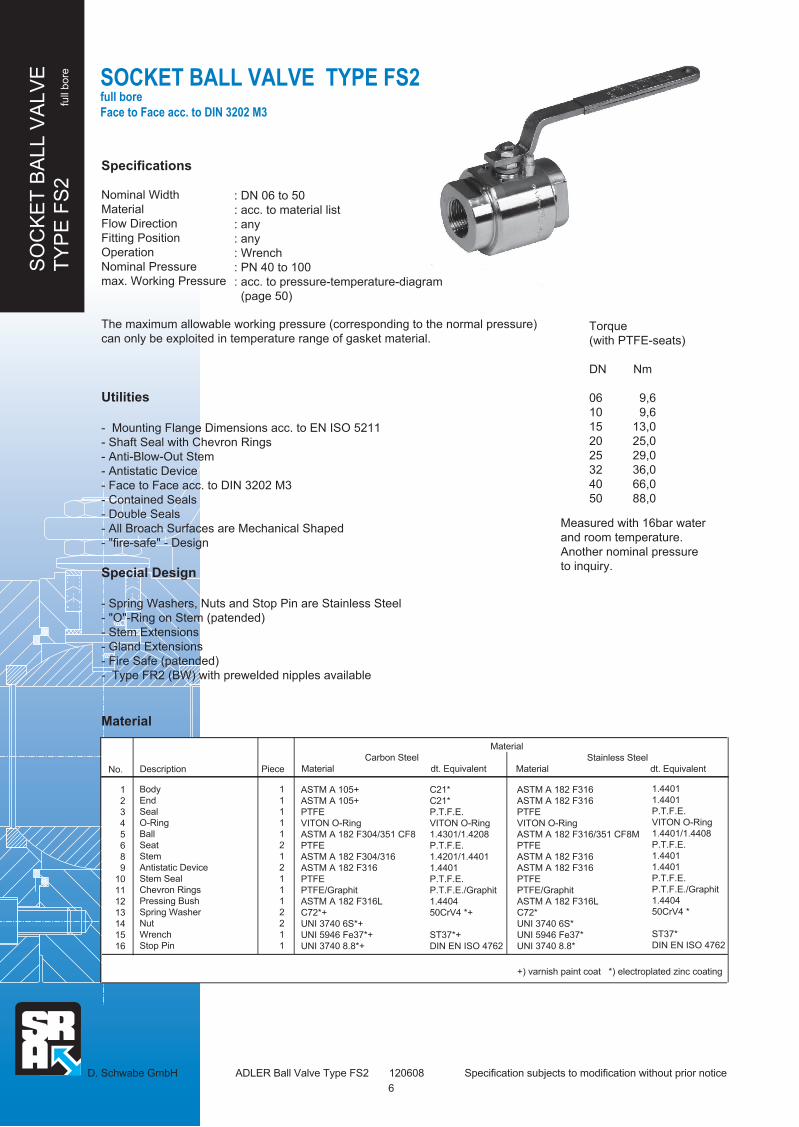
Specifications
Nominal Width
Material
Flow Direction
Fitting Position
Operation
Nominal Pressure
max. Working Pressure
The maximum allowable working pressure (corresponding to the normal pressure)
can only be exploited in temperature range of gasket material.
Utilities
- Mounting Flange Dimensions acc. to EN ISO 5211
- Shaft Seal with Chevron Rings
- Anti-Blow-Out Stem
- Antistatic Device
- Face to Face acc. to DIN 3202 M3
- Contained Seals
- Double Seals
- All Broach Surfaces are Mechanical Shaped
- "fire-safe" - Design
Special Design
- Spring Washers, Nuts and Stop Pin are Stainless Steel
- "O"-Ring on Stem (patended)
- Stem Extensions
- Gland Extensions
- Fire Safe (patended)
- Type FR2 (BW) with prewelded nipples available
Material
: DN 06 to 50
: acc. to material list
: any
: any
: Wrench
: PN 40 to 100
: acc. to pressure-temperature-diagram
(page 50)
D. Schwabe GmbH ADLER Ball Valve Type FS2 120608 Specification subjects to modification without prior notice
SOCKET BALL VALVE TYPE FS2 full bore
Face to Face acc. to DIN 3202 M3
Torque
(with PTFE-seats)
DN Nm
06 9,6
10 9,6
15 13,0
20 25,0
25 29,0
32 36,0
40 66,0
50 88,0
Measured with 16bar water
and room temperature.
Another nominal pressure
to inquiry.
Description Piece
Body
End
Seal
O-Ring
Ball
Seat
Stem
Antistatic Device
Stem Seal
Chevron Rings
Pressing Bush
Spring Washer
Nut
Wrench
Stop Pin
1
1
1
1
1
2
1
2
1
1
1
2
2
1
1
1
2
3
4
5
6
8
9
10
11
12
13
14
15
16
Carbon Steel
Material dt. Equivalent
Material
No.
C21*
C21*
P.T.F.E.
VITON O-Ring
1.4301/1.4208
P.T.F.E.
1.4201/1.4401
1.4401
P.T.F.E.
P.T.F.E./Graphit
1.4404
50CrV4 *+
ST37*+
DIN EN ISO 4762
1.4401
1.4401
P.T.F.E.
VITON O-Ring
1.4401/1.4408
P.T.F.E.
1.4401
1.4401
P.T.F.E.
P.T.F.E./Graphit
1.4404
50CrV4 *
ST37*
DIN EN ISO 4762
Stainless Steel
Material dt. Equivalent
ASTM A 105+
ASTM A 105+
PTFE
VITON O-Ring
ASTM A 182 F304/351 CF8
PTFE
ASTM A 182 F304/316
ASTM A 182 F316
PTFE
PTFE/Graphit
ASTM A 182 F316L
C72*+
UNI 3740 6S*+
UNI 5946 Fe37*+
UNI 3740 8.8*+
+) varnish paint coat *) electroplated zinc coating
ASTM A 182 F316
ASTM A 182 F316
PTFE
VITON O-Ring
ASTM A 182 F316/351 CF8M
PTFE
ASTM A 182 F316
ASTM A 182 F316
PTFE
PTFE/Graphit
ASTM A 182 F316L
C72*
UNI 3740 6S*
UNI 5946 Fe37*
UNI 3740 8.8*
6

SO
CK
ET
BA
LL V
ALV
E
TY
PE
FS
2 fu
ll bore
SOCKET BALL VALVE TYPE FS2 full bore
Face to Face acc. to DIN 3202 M3
C
Ø D1
M
H
14
16
15
13
12
11
10
8
6
5
4
1
2
3
9
DIN EN 10226
Internal Thread
L
Ø DR
V
h4
T ±1
F ±1
P
NS
4 Mounting Holes d4
O
Ø d
2
Ø d
3
D. Schwabe GmbH ADLER Ball Valve Type FS2 120608 Specification subjects to modification without prior notice
7
Dimensions in mm
DN PNSeats Seats **)
PTFE PTFE with
Metal Core
R*)
1/4"
3/8"
1/2"
3/4"
1"
1 1/4"
1 1/2"
2"
ØD
10
10
15
19
25
30
38
51
ØD1
49,5
49,5
59
64
74
80
99
119
C
30
30
38
42
50
55
70
85
H
46
46
63
65
76
80
98
108
L
50
60
75
80
90
110
120
140
M
120
120
145
145
185
185
280
280
P
17,5
17,5
23
25,5
32
36
44
54
T
5,5
5,5
7
7
8,5
8,5
10,5
10,5
P
17,5
17,5
26
28,5
41
45,5
50,5
60,5
F
11
11
14
14
16,5
16,5
19,5
19,5
S
5
5
6
6
8
8
10
10
V
8
8
10
10
12
12
16
16
06
10
15
20
25
32
40
50
*) R = Internal Thread acc. to DIN EN 10226
100 100
100 100
63 100
63 100
40 100
40 100
40 100
40 100
O
33
33
42
46
55
58
71
79
N
35
35
37
38
37
35
46
50
d2
25
25
25
25
25
25
35
35
d4
M5
M5
M5
M5
M5
M5
M6
M6
h4
1,5
1,5
1,5
1,5
2
2
2
2
EN ISO
5211
F03
F03
F03
F03
F03
F03
F05
F05
Weight
(kg)
0,6
0,65
1,2
1,4
2,2
3,2
5,2
7,8
d3
36
36
36
36
36
36
50
50

BA
LL V
ALV
E "
3 P
IEC
E"
TY
PE
FP
3
full
bore
Specifications
Nominal Width
Material
Flow Direction
Fitting Position
Operation
Nominal Pressure
max. Working Pressure
The maximum allowable working pressure (corresponding to the normal pressure)
can only be exploited in temperature range of gasket material.
Utilities
- Mounting Flange Dimensions acc. to EN ISO 5211
- Shaft Seal with Chevron Rings
- Anti Blow-out Stem
- Antistatic Device
- Guided Bolts
- Self Adjusting Ends
- Face to Face acc. to DIN 3202
- All Broach Surfaces are Mechanical Shaped
Special Design
- Spring Washers, Nuts and Stop Pin are Stainless Steel
- "O"-Ring on Stem (patended)
- Stem Extensions
- Gland Extensions
- Fire Safe (patended)
- Pocket Less Seats in PTFE
Material
: DN 06 to 100
: acc. to material list
: any
: any
: Wrench
: PN 16 to 100
: acc. to pressure-temperature-diagram
(page 50)
D. Schwabe GmbH ADLER Ball Valve Type FP3 120608 Specification subjects to modification without prior notice
BALL VALVE "3 PIECE BOLTED" TYPE FP3 with internal thread or B.W
full bore
face to face dimensions acc. to DIN 3202
Torque
(with PTFE-Seats)
DN Nm
06 9,0
10 9,0
15 11,0
20 22,0
25 27,0
32 32,0
Measured with 16bar water
and room temperature.
Another nominal pressure
to inquiry.
DN Nm
40 62
50 80
65 132
80 156
100 280
Material
No.
1
2
3
5
6
8
9
10
11
12
13
14
15
16
17
18
Descriptions
Body
End
Seal
Seat
Ball
Stem
Antistatic Device
Stem Seal
Chevron Rings
Pressing Bush
Spring Washer
Nut/Lock Nut
Wrench
Stop Pin
Screws (DIN EN 24014)
Nut (DIN EN 24032)
Piece
1
2
2
1
2
1
2
1
2
1
2
2
1
1
4 - 6
4 - 6
1.0619 +C 21/
1.0619 +
P.T.F.E.
1.4301/1.4308
P.T.F.E.
1.4001/
1.4301/1.4401
1.4401
P.T.F.E.
P.T.F.E./Graphit
1.4404
50CrV4 *+
St 37 *+
DIN EN ISO 4762
Carbon Steel
Material dt. Equivalent
Stainless Steel
Material dt. Equivalent
1.4408
1.4401/1.4408
P.T.F.E.
1.4401/1.4408
P.T.F.E.
1.4401
1.4401
P.T.F.E.
P.T.F.T./Graphit
1.4404
50CrV4 *
St 37 *
DIN EN ISO 4762
ASTM A 216 WCB+
ASTM A 105/216 WCB+
PTFE
ASTM A 182 F304/351 CF8
PTFE
ASTM A 182 F6/304/316
ASTM A 182 F316
PTFE
PTFE/Graphit
ASTM A 182 F316L
C72*+
UNI 3740 6S*+
UNI 5946 Fe37*+
UNI 3740 8.8*+
UNI 3740 8.8*+
UNI 3740 8.8*+
ASTM A 351 CF8M
ASTM A 182 F316/351 CF8M
PTFE
ASTM A 182 F316/351 CF8M
PTFE
ASTM A 182 F316
ASTM A 182 F316
PTFE
PTFE/Graphit
ASTM A 182 F316L
C72*
UNI 3740 6S*
UNI 5946 Fe37*
UNI 3740 8.8*
A2-70
A2-70
+) varnish paint coat *) electroplated zinc coating
8

BA
LL V
ALV
E "
3 P
IEC
E"
TY
PE
FP
3
full
bore
BALL VALVE "3 PIECE BOLTED" TYPE FP3
Dimensions in mm
DN PN R
1/4"
3/8"
1/2"
3/4"
1"
1 1/4"
1 1/2"
2"
2 1/2"
3"
4"
ØD
10
10
15
19
25
30
38
51
64
76
101
X
13
17
22
28
32
43
54
70
82
106
Y
18
22
28
34
42
49
61
77
90
115
E
20
20
26
28,5
37
44,6
53,6
70,5
83
96,2
118,2
L
50
60
75
80
90
110
120
140
185
205
240
M
120
120
145
145
185
185
280
280
370
370
470
G
35
35
43
49
61
67
84
102
123
143
176
H
46
46
66
68
85
91
106
116
140
148
174
N
M5
M5
M6
M6
M8
M8
M10
M10
M12
M14
M14
K
40
40
55
55
70
80
90
110
120
140
170
d1
33
33
36
36
36
36
51
51
65
65
70
d4
M5
M5
M5
M5
M5
M5
M6
M6
M8
M8
M8
06
10
15
20
25
32
40
50
65
80
100
R = Internal Thread acc. to DIN EN 10226 X/Y = Weld-on End acc. to DIN EN 12627
100
100
63
63
40
40
40
40
25
25
16
S
5
5
6
6
8
8
10
10
14
14
18
F
6,5
6,5
7,5
7,5
16,5
16,5
19,5
19,5
23,5
23,5
26,5
P
22,2
22,2
32,5
35
41
45,5
50,5
60,5
77,5
86
99,5
T
5,5
5,5
7
7
9,5
9,5
14,5
14,5
16,5
16,5
16,5
V
8
8
10
10
12
12
16
16
22
22
30
EN ISO
5211
F03
F03
F03
F03
F03
F03
F05
F05
F07
F07
F07
Gewicht
(kg)
0,30
0,35
0,75
0,85
1,35
1,75
3,30
4,90
11,00
15,00
23,50
Ø W
Ø G
H
h4
H
G
VT ±
1F
±1
P
Ø G
Ø W
H
Carbon Steel Device
Carbon Steel Device
Stainless Steel Device
N=Screw Size
K=Screw Length
N=Screw Size
K=Screw Length
M
h4
H
G
V
T ±
1F
±1
P
S
4 Mounting Holes d4
E
L
Ø d3
d1
DIN EN 10226
Ø X
Ø
DRØ
Y
Weld-on End DIN EN 12627
Internal Thread
Ø d2
15
16
Stainless Steel Device
13
1112
10
8 9
17
6
3 5
1 2
18 14
R 2 1/2" - 4"
DN 65 - 100
d2
25
25
25
25
25
25
35
35
55
55
55
d3
36
36
36
36
36
36
50
50
70
70
70
h4
1,5
1,5
1,5
1,5
2
2
2
2
2
2
2
W
44
44
54,5
63
78
84
103,5
120
148
168,5
199
M
SL
E
d1
Ø d2
Ø d3
DIN EN 10226
RØ
Y
Weld-on End
Ø D
Ø X
Internal Thread
DIN EN 12627
4 Mounting Holes d4
R 1/4" - 2"
DN 10 - 50
15
16
13
1112
9
6 8
10
3
1 2
5
17
18 14
D. Schwabe GmbH ADLER Ball Valve Type FP3 120608 Specification subjects to modification without prior notice
9

Specifications
Nominal Width
Material
Flow Direction
Fitting Position
Operation
Nominal Pressure
max. Working Pressure
The maximum allowable working pressure (corresponding to the normal pressure)
can only be exploited in temperature range of gasket material.
Utilities
- Mounting Flange acc. to EN ISO 5211
- Shaft Seal with Chevron Rings
- Anti Blow-out Stem
- Antistatic Device
- Face to Face acc. to DIN EN 558
- Contained Seats
- Double Seals
- all broach surface are mechanical shaped
- "fire-safe" - Design
Special Design
- Spring Washers, Nuts and Stop Pin are Stainless Steel
- "O"-Ring on Stem (patended)
- Stem Extensions
- Gland Extensions
- Fire Safe (patended)
: DN 10 to 250
: acc. to material list
: any
: any
: Wrench
: PN 10 to 40
: acc. to pressure-temperature-diagram
(page 50)
D. Schwabe GmbH ADLER Ball Valve Type FA1/2 FB1/2 200912 Specification subjects to modification without prior notice
BALL VALVE “WAFER TYPE”
TYPE FA1 / FA2
TYPE FB1 / FB2 full bore, split body
10
BA
LL V
ALV
E “
WA
FE
R ”
TY
PE
FA
B1/2
fu
ll bore
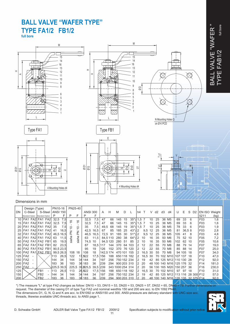
BALL VALVE “WAFER TYPE”
TYPE FA1/2 FB1/2 full bore
M
Ø D
on Ø K PCD
N Mounting Holes Q
V
h4
T ±1
F ±1
P
Ø d
3
Ø d
2
U1
M
A
H
LL
H
A
E
SØ GØ D
1
UØ d
3
Ø d
2
S
E
Ø D
1
Ø G
15
16
13
14
11
12
8
9
10
3 5 6
1
2 4
Type FB1
1613
14
15
8
9
10
11
12
5
3
6
1
2
4
Type FA1
4 Mounting Holes d44 Mounting Holes d4
Dimensions in mm
DN
10
15
20
25
32
40
50
65
80
100
125
150
200
250
125
150
200
*) The measure "L" at type FA2 changes as follow: DN10 = 53, DN15 = 53, DN20 = 53, DN25 = 57, DN32 = 65, DN40 = 79. Further dimensions on
request. The diameter of the casing D1 of type Typ FA2 und nominal weidhts 150 and 200 are acc. to EN 1092 PN40.
The dimensions D1, G, N, Q and K are acc. to EN1092 or ANSI150 und 300. ANSI-pressure are delivery standard with UNC-size acc.
threads, likewise available UNC-threads acc. to ANSI page 1.
EN ISO
5211
F03
F03
F03
F03
F03
F05
F05
F07
F07
F07
F10
F12
F14
F16
F10
F12
F14
Weight
(kg)
1,6
1,6
1,9
2,8
4,8
7,2
10,6
19,0
25,0
34,0
47,0
92,0
181,0
230,0
31,0
57,0
92,0
Design (Type)
C-Steel S-SteelStandard Option Standard Option
FA1 FA2
FA1 FA2
FA1 FA2
FA1 FA2
FA1 FA2
FA1 FA2
FA2 FA1
FA2 FA1
FA2 FA1
FA2 FA1
FA2 -
FA2 -
FA2 -
FA2 -
FA1 FA2
FA1 FA2
FA1 FA2
FA1 FA2
FA1 FA2
FA1 FA2
FA2 FB1
FA2 FB1
FA2 FB1
FA2 FB1
FB1 -
FB2 -
FB2 -
PN10-16
ANSI 150
P F
32,5 7,5
32,5 7,5
35 7,5
41 16,5
46,5 16,5
63 11,5
65 19,5
82 23,5
90,5 23,5
99,5 26,5
113 26,5
144 34
183 36
225,5 39,5
113 26,5
144 34
183 36
PN25-40
P F
108 18
122 17,5
144 34
183 36
225,5 39,5
113 26,5
144 34
183 36
sie
he
PN
10
- 1
6
sie
he
PN
10
- 1
6
ANSI 300
P F
32,5 7,5
32,5 7,5
35 7,5
42,5 16,5
46,5 16,5
63 11,5
74,5 10
87 18,5
95 19
108 18
122 17,5
144 34
183 36
225,5 39,5
122 17,5
144 34
183 36
A
47
47
49,5
67
72,5
84,5
94,5
117
126
142,5
156
197
239
239
156
197
239
H
66
66
68
85
91
110
120
144
152
174
188
256
294
343
188
256
294
M
145
145
145
185
185
280
280
370
370
470
650
750
900
1000
650
750
900
D
15
15
19
25
30
38
51
64
76
101
118
152
203
254
118
152
203
L
35*)
35*)
35*)
43*)
51*)
64*)
85
103
120
155
182
234
310
314
182
234
310
h4
1,5
1,5
1,5
2
2
2
2
2
2
2
2
2
2
2
2
2
2
T
7
7
7
9,5
9,5
10
10
12
12
16,5
16,5
19
20
20
16,5
19
20
V
10
10
10
12
12
16
16
22
22
30
30
42
48
56
30
42
48
d2
25
25
25
25
25
35
35
55
55
55
70
85
100
130
70
85
100
d3
36
36
36
36
36
50
50
70
70
70
102
125
140
165
102
125
140
d4
M5
M5
M5
M5
M5
M6
M6
M8
M8
M8
M10
M12
M16
M20
M10
M12
M16
U
69
69
78
81
105
75
102
88
85
94
107
110
125
150
97
113
135
E
33
33
33
36,5
41
52
62
79
88
105
137
130
176
257
97
116
135
S
6
6
6
8
8
10
10
14
14
18
18
28
32
36
18
28
32
D2
300
375
D. Schwabe GmbH ADLER Ball Valve Type FA1/2 FB1/2 200912 Specification subjects to modification without prior notice
BA
LL V
ALV
E “
WA
FE
R ”
TY
PE
FA
B1/2
fu
ll bore
11

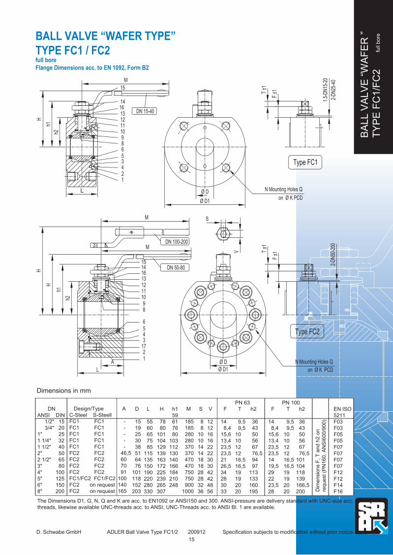
BALL VALVE “WAFER TYPE”
TYPE FA1/2 FB1/2 full bore
D. Schwabe GmbH ADLER Ball Valve Type FA1/2 FB1/2 200912 Specification subjects to modification without prior notice
Ø D
h4
V
PF
±1T
±1
E
L
h4
Ø D
V
T ±1
PF
±1
M
Ø D
1
Ø d
2
U
L
AS
Ø D
2
Ø G
E
H
1415
16
101112
6
98
3
4
1
2
5
17
13
Type FB2
4 Mounting Holes d4
on Ø K PCD
N Mounting Holes Q
on Ø d3 PCD
N Mounting Holes Q
on Ø K PCD
M
M
H
A
H
Ø G
Ø D
1
S
Ø d
2
Ø d
3
U
1415
16
DN 150 - 200
DN 50 - 125
11
12
13
8
9
10
5
6
34
17
1
2
Type FA2
4 Mounting
Holes d4
BA
LL V
ALV
E “
WA
FE
R ”
TY
PE
FA
B1/2
fu
ll bore
12

BALL VALVE “WAFER TYPE”
TYPE FA1/2 FB1/2 full bore
TECHNICAL DETAILS
Material of Type FB1/FB2
Pos.
1
2
3
4
5
6
8
9
10
11
12
13
14
15
16
17
Description
Body
End
Seal
O-Ring
Ball
Seat
Stem
Antistatic Device
Stem Seal
Chevron Rings
Pressing Bush
Spring Washer
Nut
Wrench
Stop Pin
Screws
Material
Carbon-Steel
Torque
DN Nm
10 9
15 11
20 22
25 27
32 32
40 62
50 80
Measured with 16bar water and room temperature. Another nominal pressure to inquiry.
D. Schwabe GmbH ADLER Ball Valve Type FA1/2 FB1/2 200912 Specification subjects to modification without prior notice
BA
LL V
ALV
E “
WA
FE
R ”
TY
PE
FA
B1/2
fu
ll bore
Material of Type FA1/FA2
Pos.
1
2
3
4
5
6
8
9
10
11
12
13
14
15
16
17
Description
Body
End
Seal
O-Ring
Ball
Seat
Stem
Antistatic Device
Stem Seal
Chevron Rings
Pressing Bush
Spring Washer
Nut
Wrench
Stop Pin
Screws
Piece
1
1
1
1
1
2
1
2
1
1
1
2
2
1
1
div.
ASTM A 105+
ASTM A 105+
PTFE
VITON O-Ring
ASTM A 182 F304/351 CF
PTFE
ASTM A 182 F304/316
ASTM A 182 F316
PTFE
PTFE/Graphit
ASTM A 182 F316L
C72*+
UNI 3740 6S*+
UNI 5946 Fe37*+
UNI 3740 8.8*+
UNI 3740 8.8*+
ASTM A 182 F316
ASTM A 182 F316
PTFE
VITON O-Ring
ASTM A 182 F316/351 CF8M
PTFE
ASTM A 182 F316
ASTM A 182 F316
PTFE
PTFE/Graphit
ASTM A 182 F316L
C72*+
UNI 3740 6S*+
UNI 5946 Fe37*+
UNI 3740 8.8*+
A2-70*+
Material
Carbon-Steel
Material german Equivalent
Stainless-Steel
Material german Equivalent
1.4401
1.4401
PTFE
VITON O-Ring
1.4401/1.4408
PTFE
1.4401
1.4401
PTFE
PTFE/Graphit
1.4404
50CrV4 *
DIN EN ISO 4762 *
St 37 *+
DIN EN ISO 4762 *
DIN EN ISO 4762
C 21 +
C 21 +
PTFE
VITON O-Ring
1.301/1.4308
PTFE
1.4301/1.4401
1.4401
PTFE
PTFE/Graphit
1.4404
50CrV4 *+
DIN EN ISO 4762
St 37 *+
DIN EN ISO 4762*+
DIN EN ISO 4762*+
+) lacquered *) electrogalvanize
1.4401
1.4401
PTFE
VITON O-Ring
1.4401/1.4408
PTFE
1.4401
1.4401
PTFE
PTFE/Graphit
1.4404
50CrV4 *
DIN EN ISO 4762 *
St 37 *+
DIN EN ISO 4762 *
DIN EN ISO 4762
Piece
1
1
1
1
1
2
1
2
1
1
1
2
2
1
1
div.
+) lacquered *) electrogalvanize
ASTM A 351 CF8/CF8M
ASTM A 351 F316/351 CF8M
PTFE
VITON O-Ring
ASTM A 182 F316/351 CF8M
PTFE
ASTM A 182 F316
ASTM A 182 F316
PTFE
PTFE/Graphit
ASTM A 182 F316L
C72*+
UNI 3740 6S*+
UNI 5946 Fe37*+
UNI 3740 8.8*+
A2-70*+
Stainless-Steel
Material german Equivalent
DN Nm
65 132
80 156
100 280
125 316
150 680
200 1020
13

Specifications
Nominal Width
Material
Flow Direction
Fitting Position
Operation
Nominal Pressure
max. Working Pressure
The maximum allowable working pressure (corresponding to the normal pressure)
can only be exploited in temperature range of gasket material.
Utilities
- Mounting Flange acc. to EN ISO 5211
- Chevron Rings
- Anti Blow-out Stem
- Antistatic Device
- Double Seals and Metal Beating End
- Contents Ball
- Contained Seats
- all broach surface are mechanical shaped
- "fire-safe" - Design
Special Design
- Spring Washers, Nuts and Stop Pin are Stainless Steel
- "O"-Ring on Stem (patended)
- Stem Extensions
- Gland Extensions
- Fire Safe (patended)
- End Tank ssembling
- Metallic Pocket Less Seats (FC2)
: DN 15 to100
: acc. to material list
: any
: any
: Wrench (optional gearbox)
: PN 63 to 100 bzw. ANSI 600
: acc. to pressure-temperature-diagram
(page 50)
D. Schwabe GmbH ADLER Ball Valve Type FC1/2 200912 Specification subjects to modification without prior notice
BALL VALVE “WAFER TYPE”
TYPE FC1 / FC2 full bore
Flange Dimensions acc. to EN 1092, Form B2
Material
BA
LL V
ALV
E “
WA
FE
R ”
TY
PE
FC
1/F
C2
fu
ll bore
Pos.
1
2
3
4
5
6
8
9
10
11
12
13
14
15
16
17
Descriptions
Body
End
Seal
O-Ring
Ball
Seat
Stem
Antistatic Device
Stem Seal
Chevron Rings
Pressing Bush
Spring Washer
Nut
Wrench
Stop Pin
Screw
Anzahl
1
1
1
1
1
2
1
2
1
1
1
2
2
1
1
1
ASTM A 105+
ASTM A 105+
PTFE
VITON O-Ring
ASTM A 182 F304/351 CF8
PTFE with Metal Core
ASTM A 182 F304/316/6
ASTM A 182 F304
PTFE
PTFE/Graphit
ASTM A 182 F316L
C72*+
UNI 3740 6S*+
UNI 5946 Fe37*+
UNI 3740 8.8*+
UNI 3740 8.8*+
Carbon-Steel
Material german Equivalent
C 21 +
C 21 +
PTFE
VITON O-Ring
1.4301/1.4308
PTFE with Metal Core
1.4301/1.4401/1.4001
1.4301
PTFE
PTFE/Graphit
1.4404
50CrV4 *+
St 37 *+
DIN EN ISO 4762 *+
DIN EN ISO 4762 *+
ASTM A 182 F316/351 CF8M
ASTM A 182 F316/351 CF8M
PTFE
VITON O-Ring
ASTM A 182 F316/351 CF8M
PTFE with Metal Core
ASTM A 182 F316
ASTM A 182 F316
PTFE
PTFE/Graphit
ASTM A 182 F316L
C72*+
UNI 3740 6S*+
UNI 5946 Fe37*+
UNI 3740 8.8*+
UNI 3740 8.8*+
1.4401/1.4408
1.4401/1.4408
PTFE
VITON O-Ring
1.4401/1.4408
PTFE with Metal Core
1.4401
1.4401
PTFE
PTFT/Graphit
1.4404
50CrV4 *
St 37 *
DIN EN ISO 4762 *
DIN EN ISO 4762 *
Material
Stainless-Steel
Material german Equivalent
+) lacquered *) electrogalvanize
14
BA
LL V
ALV
E “
WA
FE
R ”
TY
PE
FC
1/F
C2
fu
ll bore
Dimensions in mm
DN
ANSI DIN
1/2" 15
3/4" 20
1" 25
1 1/4" 32
1 1/2" 40
2" 50
2 1/2" 65
3" 80
4" 100
5" 125
6" 150
8" 200
The Dimensions D1, G, N, Q and K are acc. to EN1092 or ANSI150 and 300. ANSI-pressure are delivery standard with UNC-size acc.
threads, likewise available UNC-threads acc. to ANSI; UNC-Threads acc. to ANSI Bl. 1 are available.
EN ISO
5211
F03
F03
F05
F05
F07
F07
F07
F07
F12
F12
F14
F16
Design/Type
C-Steel S-Steell
FC1 FC1
FC1 FC1
FC1 FC1
FC1 FC1
FC1 FC1
FC2 FC2
FC2 FC2
FC2 FC2
FC2 FC2
FC1/FC2 FC1/FC2
FC2 on request
FC2 on request
A
-
-
-
-
-
46,5
60
70
91
100
140
165
H
78
80
101
104
129
139
163
172
225
239
265
307
M
185
185
280
280
370
370
470
470
750
750
900
1000
D
15
19
25
30
38
51
64
76
101
118
152
203
L
55
60
65
75
85
115
135
150
190
220
280
330
F
14
8,4
15,6
13,4
23,5
23,5
21
26,5
34
28
30
33
PN 63
T
9,5
9,5
10
10
12
12
16,5
16,5
19
19
20
20
V
12
12
16
16
22
22
30
30
42
42
48
56
h1
59
61
76
80
103
112
130
140
166
184
210
248
h2
36
43
50
56
67
76,5
94
97
113
133
160
195
F
14
8,4
15,6
13,4
23,5
23,5
14
19,5
29
22
23,5
28
PN 100
T
9,5
9,5
10
10
12
12
16,5
16,5
19
19
20
20
h2
36
43
50
56
67
76,5
101
104
118
139
166,5
200
S
8
8
10
10
14
14
18
18
28
28
32
36 Dim
ensio
ns F
, T
and h
2 o
n
request (P
N160, A
NS
I600/9
00)
1.5-
DN
15-2
0
2-D
N25
-40
F ±1T
±1
BALL VALVE “WAFER TYPE”
TYPE FC1 / FC2 full bore
Flange Dimensions acc. to EN 1092, Form B2
M
H
Ø D
Ø D1
L
h2
h1
N Mounting Holes Q
on Ø K PCD
DN 15-40
15
16
1213
14
11
910
6 5 3
8
4
1 2
S
V
M
M
H
Ø D1
Ø D
h1
H
h2
L
A
on Ø K PCD
N Mounting Holes Q
141613
15
12
1011
89
5
34
17
12
6
DN 100-200
DN 50-80
Type FC1
2-D
N50
-200
F ±1
T ±1
Type FC2
15
D. Schwabe GmbH ADLER Ball Valve Type FC1/2 200912 Specification subjects to modification without prior notice

BALL VALVE “WAFER TYPE”
WITH HEATING JACKET TYPE FX1 / FX2 full bore
L
DN 10 - 40
Base Model
Type FX1
FA1
Ø D
2
Ø F
E
Ø D
4
R
H
FlangeConnection Heating Jacket
Internal ThreadConnection Heating Jacket
Ø F
Ø D
2
Ø D
E
4
H
R
FlangeConnection Heating JacketConnection Heating Jacket
Internal Thread
L1
L
DN 150 - 200
DN 50 - 125
Type FX2
Base Model
FA2
D. Schwabe GmbH ADLER Ball Valve Type FX1/2 200912 Specification subjects to modification without prior notice
DN
Type/ C-Steel
Description S-Steel
D
E
H
L
L1
D2
F
R
10 15 20 25 32 40 50 65 80 100 125 150 200
FX1 FX1 FX1 FX1 FX1 FX1 FX2 FX2 FX2 FX2 FX2 FX2 FX2
FX1 FX1 FX1 FX1 FX1 FX1 FX2 FX2 FX2 FX2 see page 15
15 15 19 25 30 38 51 64 76 101 118 152 203
170 170 180 190 210 230 250 270 300 340 360 420 500
0 0 0 0 25 30 30 45 50 70 80 95 130
35 35 35 43 51 64 85 103 120 155 182 234 310
- - - - - - 34 43 47 56 70 117 155
15 15 15 15 15 15 15 15 15 25 25 25 25
95 95 95 95 95 95 95 95 95 115 115 115 115
1/2" 1/2" 1/2" 1/2" 1/2" 1/2" 1/2" 1/2" 1/2" 1" 1" 1" 1"
BA
LL V
ALV
E “
WA
FE
R ”
TY
PE
FX
1/F
X2
fu
ll bore
16

BALL VALVE “WAFER TYPE”
WITH HEATING JACKET TYPE FY1 / FY2 full bore
Ø D E H L Z F D2 R
118 360 80 182 110 115 25 1"
152 420 95 234 120 115 25 1"
203 500 130 310 180 115 25 1"
Stainless Steel in
Nominal Width 10 - 100
acc. to FX1 / FX2
Ø F
4
Ø D
E
Ø D
2
Ø F
Ø D
2
4
R
H
Z
L
R
FlangeConnection Heating JacketConnection Heating Jacket
Internal Thread
Type FY1 Base Model FB1
DN 125
Ø D
E
FlangeInternal ThreadConnection Heating Jacket
H
Type FY2 Base Model FB2
All dimension and material description acc. to ball valve type FB1 and FB2
DN
125
150
200
L
Z
DN 150 - 200
BA
LL V
ALV
E “
WA
FE
R ”
TY
PE
FY
1/F
Y2
fu
ll bore
17
D. Schwabe GmbH ADLER Kugelhahn Typ FY1/2 200912 Specification subjects to modification without prior notice
Connection Heating Jacket

BALL VALVE “WAFER TYPE”
TYPE FM2 / FN2
full bore, split body
BA
LL V
ALV
E “
WA
FE
R ”
TY
PE
FM
2/F
N2
full
bore
18
Specifications
Nominal Width
Material
Flow Direction
Fitting Position
Operation
Nominal Pressure
max. Working Pressure
The maximum allowable working pressure (corresponding to the normal pressure)
can only be exploited in temperature range of gasket material.
Utilities
- Mounting Flange acc. to EN ISO 5211
- Shaft Seal with Chevron Rings
- Anti Blow-out Stem
- Antistatic Device
- Contained Seats
- Double Seals
- Body - End Centering
- all broach surface are mechanical shaped
- "fire-safe" - Design
Special Design
- Spring Washers, Nuts and Stop Pin are Stainless Steel
- "O"-Ring on Stem (patended)
- Stem Extensions
- Gland Extensions
- Fire Safe (patended)
- Pocketless Seats
- Overpressure Hole into Ball
: DN 15 to 300
: acc. to material list
: any
: any
: Wrench (optional Gear Box)
: PN 10 to 40
: acc. to pressure-temperature-diagram
(page 50)
D. Schwabe GmbH ADLER Ball Valve Type FM/N2 240912 Specification subjects to modification without prior notice

BALL VALVE “WAFER TYPE”
TYPE FM2 / FN2full bore, split body
Dimensions in mm
Types FM2/FN2 DN 15 - DN 80
M
E
L = FM2
L1 = FN2
H
Ø D
acc. to DIN EN 558-1
Flange Dimensions
15
14
13
16
22
11
10
9
6
5
4
8
3
2
1
17
12
O
S
Ø d
2
N
4 Mounting Holes d4
on Ød3 PCD h4
V
F ±1
P
T ±1
D. Schwabe GmbH ADLER Ball Valve Type FM/N2 240912 Specification subjects to modification without prior notice
ØD
15
19
25
30
38
51
64
76
E
49
51,5
50
51,5
59
61,5
70,5
73
H
86
88
113
119
110
120
144
152
L
115
120
125
130
140
150
170
180
N
58
58
58
58
72,5
72,5
90
90
O
35
35
35
35
46,5
46,5
64,5
64,5
M
145
145
185
185
280
280
370
370
S
6
6
8
8
10
10
14
14
Ød2
25
25
25
25
35
35
55
55
Ød3
36
36
36
36
50
50
70
70
d4
M5
M5
M5
M5
M6
M6
M8
M8
.. ..
F
6,6
6,6
8,2
8,2
9,7
9,7
11
11
h4
1,5
1,5
1,5
1,5
2
2
2
2
P
33,1
35,4
49,3
54,8
64,8
74,8
93,5
102
T
7
7
9,5
9,5
10
10
12
12
V
10
10
12
12
16
16
22
22
EN ISO
5211
F03
F03
F03
F03
F05
F05
F07
F07
Weight
(kg)
3,0
4,0
5,2
7,0
10,0
13,5
21,5
26,0
DN
15
20
25
32
40
50
65
80
L1
130
150
160
180
200
230
290
310
BA
LL V
ALV
E “
WA
FE
R ”
TY
PE
FM
2/F
N2
full
bore
19

D. Schwabe GmbH ADLER Ball Valve Type FM/N2 240912 Specification subjects to modification without prior notice
BALL VALVE “WAFER TYPE”
TYPE FM2 / FN2full bore, split body
Types FM2/FN2 DN 100 - DN 300
Dimensions in mm
ØD
101
118
152
203
254
305
387
E
85
100
144
180
196
237
381
H
174
188
256
294
343
381
L
190
325
350
400
450
500
762
N
70
97
112
130
153
153
288
O
65
93
113
130
153
153
288
M
470
650
750
900
1000
1000
S
18
18
28
32
36
36
Ød2
55
70
85
100
130
130
200
Ød3
70
102
125
140
165
165
254
d4
M8
M10
M12
M16
M20
M20
Ø18
.. ..
F
26,5
26,5
34
36
44
44
h4
2
2
2
2
3
3
3
P
99,5
113
144
183
220
258,5
419
T
16,5
16,5
19
20
20
20
V
30
30
42
48
56
56
EN ISO
5211
F07
F10
F12
F14
F16
F16
F25
Weight
(kg)
30,5
61 50*)
96 70*)
157 120*)
215 175*)
255 200*)
930
DN
100
125
150
200
250
300
400
*) different weight for stainless steel device
L1
350
400
480
600
730
850
V
h4
F ±1
T ±1
P
O
N
Ø d
2
S
4 Mounting Holes d4
on Ød3 PCD
Ø D
acc. to DIN EN 558-1
Flange Dimensions
M
H
H
L = FM2
E
L1 = FN2
DN 150-300
DN 100-125
15
14
13
12
11
10
9
8
6
16
4
3
2
1
17
5
M
BA
LL V
ALV
E “
WA
FE
R ”
TY
PE
FM
2/F
N2
full
bore
20

BALL VALVE “WAFER TYPE”
TYPE FM2 / FN2full bore, split body
Material
Pos.
1
2
3
4
5
6
8
9
10
11
12
13
14
15
16
17
22
Description
Body
End
Seal
O-Ring
Ball
Seat
Stem
Antistatic Device
Stem Seal
Chevron Rings
Pressing Bush
Spring Washer
Nut
Wrench
Stop Pin
Screw
DIN-Adapter Plate
Piece
1
1
1
1
2
1
2
1
1
1
2
2
1
1
1
div.
1
german Equivalent
C 21/1.0619 +
C 21/1.0619 +
PTFE
VITON O-Ring
1.301/1.4308
PTFE
1.4301/1.4401
1.4401
PTFE
PTFE/Graphit
1.4404
50CrV4 *+
DIN EN ISO 4762
St 37 *+
DIN EN ISO 4762 *+
DIN EN ISO 4762 *+
ASTM A 351 CF8M +
Torque
DN Nm
15 11
20 22
25 27
32 32
40 62
50 80
65 132
Measured with 16bar water and room temperature. Another nominal pressure to inquiry.
DN Nm
80 156
100 280
125 318
150 680
200 1020
250 1600
300 2400
TECHNICAL DETAILS
Material
ASTM A 105/216 WCB+
ASTM A 105/216 WCB+
PTFE
VITON O-Ring
ASTM A 182 F304/351 CF8
PTFE
ASTM A 182 F304/316
ASTM A 182 F316
PTFE
PTFE/Graphit
ASTM A 182 F316L+
C72*+
UNI 3740 6S*+
UNI 5946 Fe37*+
UNI 3740 8.8*+
UNI 3740 8.8*+
ASTM A 351 CF8M+
Material
Carbon-Steel Stainless-Steel
Material
ASTM A 182 F316/351 CF8M
ASTM A 182 F316/351 CF8M
PTFE
VITON O-Ring
ASTM A 182 F316/351 CF8M
PTFE
ASTM A 182 F316
ASTM A 182 F316
PTFE
PTFE/Graphit
ASTM A 182 F316L
C72*
UNI 3740 6S*
UNI 5946 Fe37*+
UNI 3740 8.8*
A2-70
ASTM A 351 CF8M
+) lacquered *) electrogalvanize
german Equivalent
1.4401/1.4408
1.4401/1.4408
PTFE
VITON O-Ring
1.4401/1.4408
PTFE
1.4401
1.4401
PTFE
PTFE/Graphit
1.4404
50CrV4 *
DIN EN ISO4762 *
St 37 *+
DIN EN ISO 4762*
DIN EN 24017
1.4408
BA
LL V
ALV
E “
WA
FE
R ”
TY
PE
FM
2/F
N2
full
bore
21
D. Schwabe GmbH ADLER Ball Valve Type FM/N2 240912 Specification subjects to modification without prior notice
BA
LL V
ALV
E “
WA
FE
R ”
TY
PE
FE
2/F
F2
full
bore
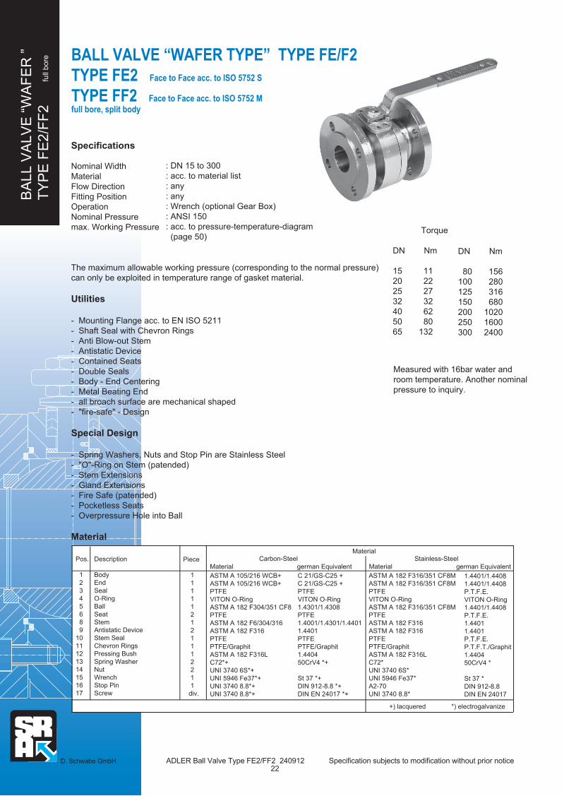
Torque
DN Nm
15 11
20 22
25 27
32 32
40 62
50 80
65 132
Measured with 16bar water and
room temperature. Another nominal
pressure to inquiry.
BALL VALVE “WAFER TYPE” TYPE FE/F2
TYPE FE2 Face to Face acc. to ISO 5752 S
TYPE FF2 Face to Face acc. to ISO 5752 M full bore, split body
Specifications
Nominal Width
Material
Flow Direction
Fitting Position
Operation
Nominal Pressure
max. Working Pressure
The maximum allowable working pressure (corresponding to the normal pressure)
can only be exploited in temperature range of gasket material.
Utilities
- Mounting Flange acc. to EN ISO 5211
- Shaft Seal with Chevron Rings
- Anti Blow-out Stem
- Antistatic Device
- Contained Seats
- Double Seals
- Body - End Centering
- Metal Beating End
- all broach surface are mechanical shaped
- "fire-safe" - Design
Special Design
- Spring Washers, Nuts and Stop Pin are Stainless Steel
- "O"-Ring on Stem (patended)
- Stem Extensions
- Gland Extensions
- Fire Safe (patended)
- Pocketless Seats
- Overpressure Hole into Ball
Material
: DN 15 to 300
: acc. to material list
: any
: any
: Wrench (optional Gear Box)
: ANSI 150
: acc. to pressure-temperature-diagram
(page 50)
DN Nm
80 156
100 280
125 316
150 680
200 1020
250 1600
300 2400
D. Schwabe GmbH ADLER Ball Valve Type FE2/FF2 240912 Specification subjects to modification without prior notice 22
Pos.
1
2
3
4
5
6
8
9
10
11
12
13
14
15
16
17
Description
Body
End
Seal
O-Ring
Ball
Seat
Stem
Antistatic Device
Stem Seal
Chevron Rings
Pressing Bush
Spring Washer
Nut
Wrench
Stop Pin
Screw
Piece
1
1
1
1
1
2
1
2
1
1
1
2
2
1
1
div.
ASTM A 105/216 WCB+
ASTM A 105/216 WCB+
PTFE
VITON O-Ring
ASTM A 182 F304/351 CF8
PTFE
ASTM A 182 F6/304/316
ASTM A 182 F316
PTFE
PTFE/Graphit
ASTM A 182 F316L
C72*+
UNI 3740 6S*+
UNI 5946 Fe37*+
UNI 3740 8.8*+
UNI 3740 8.8*+
1.4401/1.4408
1.4401/1.4408
P.T.F.E.
VITON O-Ring
1.4401/1.4408
P.T.F.E.
1.4401
1.4401
P.T.F.E.
P.T.F.T./Graphit
1.4404
50CrV4 *
St 37 *
DIN 912-8.8
DIN EN 24017
+) lacquered *) electrogalvanize
Carbon-Steel
Material german Equivalent
Material Stainless-Steel
Material german Equivalent
C 21/GS-C25 +
C 21/GS-C25 +
PTFE
VITON O-Ring
1.4301/1.4308
PTFE
1.4001/1.4301/1.4401
1.4401
PTFE
PTFE/Graphit
1.4404
50CrV4 *+
St 37 *+
DIN 912-8.8 *+
DIN EN 24017 *+
ASTM A 182 F316/351 CF8M
ASTM A 182 F316/351 CF8M
PTFE
VITON O-Ring
ASTM A 182 F316/351 CF8M
PTFE
ASTM A 182 F316
ASTM A 182 F316
PTFE
PTFE/Graphit
ASTM A 182 F316L
C72*
UNI 3740 6S*
UNI 5946 Fe37*
A2-70
UNI 3740 8.8*

BA
LL V
ALV
E “
WA
FE
R ”
TY
PE
FE
2/F
F2
full
boreBALL VALVE “WAFER TYPE” TYPE FE/F2
TYPE FE2 Face to Face acc. to ISO 5752 S
TYPE FF2 Face to Face acc. to ISO 5752 M full bore, split body
D. Schwabe GmbH ADLER Ball Valve Type FE2/FF2 240912 Specification subjects to modification without prior notice
Dimensions in mm
DN D
15
19
25
30
38
51
64
76
101
118
152
203
254
305
387
E
46
48,5
49
52
58
76
72
75
77
100
117
155
196
237
381
H
86
88
113
119
110
120
144
152
174
188
256
294
343
381
L
108
117
127
140
165
178
190
203
229
254
267
419
L1
203
241
305
394
457
533
610
762
N
35
35
37
45
46
48
63
63
70
97
112
130
153
153
288
O
33
33
33
33
45
45
62
62
65
93
113
130
153
153
288
S
6
6
8
8
10
10
14
14
18
18
28
32
36
36
Ød2
25
25
25
25
35
35
55
55
55
70
85
100
130
130
200
Ød3
36
36
36
36
50
50
70
70
70
102
125
140
165
165
254
d4
M5
M5
M5
M5
M6
M6
M8
M8
M8
M10
M12
M16
M20
M20
Ø18
15 .. ..
20
25
32
40 50
65 80
100
125
150
200
250
300
400
Flange dimensions acc. to respective ANSI-Norm *) different weight for stainless steel device
F
7,5
7,5
16,5
16,5
19,5
19,5
23,5
23,5
26,5
26,5
34
36
44
44
h4
1,5
1,5
2
2
2
2
2
2
2
2
2
2
3
3
3
P
32,5
35,5
41
46,5
55
65
82
86
99,5
113
144
183
220
258,5
419
T
7
7
9,5
9,5
10
10
12
16,5
16,5
16,5
19
20
20
20
V
10
10
12
12
16
16
22
22
30
30
42
48
56
56
EN ISO
5211
F03
F03
F03
F03
F05
F05
F07
F07
F07
F10
F12
F14
F16
F16
F25
Weight
(kg)
2,7
3,6
4,5
6,2
9
14,3
21,3
25
34
56 48*)
91 67*)
159 121*)
DN15 -125
DN150 - 300
DØ
O
Sd2Ø
d3Ø
N
4 Mounting Holes d4
V
h4
F ±1
T ±1
P
H
L1
E
15
1614
12
1011
13
6
8 9
5
4
1
2 17
3
M
= FF2
M
H
L = FE2
M
145
145
185
185
280
280
370
370
470
650
750
900
1000
1000
23

BA
LL V
ALV
E “
WA
FE
R ”
TY
PE
FG
2
full
bore
Torque
DN Nm
1/2" 11
3/4" 22
1" 27
1 1/4" 32
1 1/2" 62
2" 80
Measured with 16bar water
and room temperature.
Another nominal pressure to
inquiry.
BALL VALVE “WAFER TYPE” TYPE FG2
Face to Face acc. to DIN EN 558-2 full bore
: DN 1/2" to 8"
: ac. to material list
: any
: any
: Wrench (optional Gear Box)
: ANSI 300
: acc. to pressure-temperature-diagram
(page 50)
D. Schwabe GmbH ADLER Ball Valve Type FG2 240912 Specification subjects to modification without prior notice
DN Nm
2 1/2" 132
3" 156
4" 280
5" 316
6" 680
8" 1020
24
Specifications
Nominal Width
Material
Flow Direction
Fitting Position
Operation
Nominal Pressure
max. Working Pressure
The maximum allowable working pressure (corresponding to the normal pressure)
can only be exploited in temperature range of gasket material.
Utilities
- Mounting Flange acc. to EN ISO 5211
- Shaft Seal with Chevron Rings
- Anti Blow-out Stem
- Antistatic Device
- Contained Seats
- Double Seals
- Body - End Centering
- all broach surface are mechanical shaped
- "fire-safe" - Design
Special Design
- Spring Washers, Nuts and Stop Pin are Stainless Steel
- "O"-Ring on Stem (patended)
- Stem Extensions
- Gland Extensions
- Fire Safe (patended)
- Pocketless Seats
- Overpressure Hole into Ball
Material
Pos.
1
2
3
4
5
6
8
9
10
11
12
13
14
15
16
17
Description
Body
End
Seal
O-Ring
Ball
Seat
Stem
Antistatic Device
Stem Seal
Chevron Rings
Pressing Bush
Spring Washer
Nut
Wrench
Stop Pin
Screw
Piece
1
1
1
1
1
2
1
2
1
1
1
2
2
1
1
div.
german Equivalent
C 21 +
C 21 +
PTFE
VITON O-Ring
1.4301/1.4308
PTFE
1.4001/1.4301/1.4401
1.4401
PTFE
PTFE/Graphit
1.4404
50CrV4 *+
St 37 *+
DIN EN ISO 4762 *+
DIN EN ISO 24017 *+
Material
ASTM A 105+
ASTM A 105+
PTFE
VITON O-Ring
ASTM A 182 F304/351 CF8
PTFE
ASTM A 182 F304/316/6
ASTM A 182 F316
PTFE
PTFE/Graphit
ASTM A 182 F316L
C72*+
UNI 3740 6S*+
UNI 5946 Fe37*+
UNI 3740 8.8*+
UNI 3740 8.8*+
Material
Carbon-Steel Stainless-Steel
Material
ASTM A 182 F316/351 CF8M
ASTM A 182 F316/351 CF8M
PTFE
VITON O-Ring
ASTM A 182 F316/351 CF8M
PTFE
ASTM A 182 F316
ASTM A 182 F316
PTFE
PTFE/Graphit
ASTM A 182 F316L
C72*
UNI 3740 6S*
UNI 5946 Fe37*+
A2-70UNI 3740 8.8*
UNI 3740 8.8*
+) lacquered *) electrogalvanize
german Equivalent
1.4401/1.4408
1.4401/1.4408
PTFE
VITON O-Ring
1.4401/1.4408
PTFE
1.4401
1.4401
PTFE
PTFE/Graphit
1.4404
50CrV4 *
St 37 *+
DIN EN ISO 4762*
DIN EN 24017

BA
LL V
ALV
E “
WA
FE
R ”
TY
PE
FG
2
full
boreBALL VALVE “WAFER TYPE” TYPE FG2
Face to Face acc. to DIN EN 558-2 full bore
D. Schwabe GmbH ADLER Ball Valve Type FG2 240912 Specification subjects to modification without prior notice
Dimensions in mm
.. ..
DN
1/2"
3/4"
1"
1 1/4"
1 1/2"
2"
2 1/2"
3"
4"
5"
6"
8"
D
15
19
25
30
38
51
64
76
101
118
152
203
E
57,5
58,5
59,5
71
69
82
89
109
94
135
154
180,5
H
86
88
113
119
110
120
144
152
174
188
256
294
L
140
151
165
179
191
216
241
283
305
381
403
502
N
50
48
54
73
67
64
79
80
94
96
125
123
O
34
33
34
43
46
48
65
80
67
92
143,5
180
S
6
6
8
8
10
10
14
14
18
18
28
32
Ød2
25
25
25
25
35
35
55
55
55
70
85
100
Ød3
36
36
36
36
50
50
70
70
70
102
125
140
d4
M5
M5
M5
M5
M6
M6
M8
M8
M8
M10
M12
M16
Flange dimensions acc. with the respective ANSI-Norm *) difference weight in stainless steel device
F
7,5
7,5
16,5
16,5
19,5
19,5
23,5
23,5
26,5
26,5
34
36
h4
1,5
1,5
2
2
2
2
2
2
2
2
2
2
P
32,5
35
41
46,5
55
65
82
90,5
99,5
113
144
183
T
7
7
9,5
9,5
10
10
12
16,5
16,5
16,5
19
20
V
10
10
12
12
16
16
22
22
30
30
42
48
EN ISO
5211
F03
F03
F03
F03
F05
F05
F07
F07
F07
F10
F12
F14
Weight
(kg)
4,0
5,2
6,8
11
14
19
28
38
54
70
130 82*)
190 130*)
M
145
145
185
185
280
280
370
370
470
650
750
900
Ø D
H
E
DN 6"-8"
DN 1/2"-5"
1416
12
10
11
13
15
9
8
5
4
6
3
2
1
17
M
M
H
L
V
h4
T ±1
F ±1
P
O
S
Ø d
2
Ø d
3
N
4 Mounting Holes d4
25

BA
LL V
ALV
E “
WA
FE
R ”
TY
PE
FH
/N2 fu
ll bore
BALL VALVE “WAFER TYPE” TYPE FH/FN2
TYPE FH2 Face to Face acc. to ISO 5752 S
TYPE FN2 Face to Face acc. to DIN EN 558 full bore
Specifications
Nominal Width
Material
Flow Direction
Fitting Position
Operation
Nominal Pressure
max. Working Pressure
The maximum allowable working pressure (corresponding to the normal pressure)
can only be exploited in temperature range of gasket material.
Utilities
- Mounting Flange acc. to EN ISO 5211
- Shaft Seal with Chevron Rings
- Anti Blow-out Stem
- Antistatic Device
- Contained Seats
- Double Seals
- Body - End Centering
- all broach surface are mechanical shaped
- "fire-safe" - Design
Special Design
- Spring Washers, Nuts and Stop Pin are Stainless Steel
- "O"-Ring on Stem (patended)
- Stem Extensions
- Gland Extensions
- Fire Safe (patended)
- Pocketless Seats
Material
: DN 15 to 150 or 1/2" bis 6"
: acc. to material list
: any
: any
: Wrench (optional Gear Box)
: PN 63 - 100 or ANSI 600 - 900
: acc. to pressure-temperature-diagram
(page 50)
Pos.
1
2
3
4
5
6
8
9
10
11
12
13
14
15
16
17
Description
Body
End
Seal
O-Ring
Ball
Seat
Stem
Antistatic Device
Stem Seal
Chevron Rings
Pressing Bush
Spring Washer
Nut
Wrench
Stop Pin
Screw
Piece
1
1
1
1
1
2
1
2
1
1
1
2
2
1
1
div.
ASTM A 105+
ASTM A 105+
PTFE
VITON O-Ring
ASTM A 182 F304/351 CF8
PTFE with Metal Core
ASTM A 182 F6/316
ASTM A 182 F316
PTFE
PTFE/Graphit
ASTM A 182 F316L
C72*+
UNI 3740 6S*+
UNI 5946 Fe37*+
UNI 3740 8.8*+
UNI 3740 8.8*+
Carbon-Steel
Material german Equivalent
D. Schwabe GmbH ADLER Ball Valve Type FH/N2 240912 Specification subjects to modification without prior notice
Material Stainless-Steel
Material german Equivalent
1.4401/1.4408
1.4401/1.4408
PTFE
VITON O-Ring
1.4401/1.4408
PTFE with Metal Core
1.4401
1.4401
PTFE
PTFT/Graphit
1.4404
50CrV4 *
St 37 *
DIN EN ISO 4762
DIN EN 24017
+) lacquered *) electrogalvanize
C 21+
C 21+
PTFE
VITON O-Ring
1.4301/1.4308
PTFE with Metal Core
1.4001/1.4401
1.4401
PTFE
PTFE/Graphit
1.4404
50CrV4 *+
St 37 *+
DIN EN ISO 4762 *+
DIN EN 24017 *+
ASTM A 182 F316/351 CF8M
ASTM A 182 F316/351 CF8M
PTFE
VITON O-Ring
ASTM A 182 F316/351 CF8M
PTFE with Metal Core
ASTM A 182 F316
ASTM A 182 F316
PTFE
PTFE/Graphit
ASTM A 182 F316L
C72*+
UNI 3740 6S*
UNI 5946 Fe37*
UNI 3740 8.8*
A2-70
26

BA
LL V
ALV
E “
WA
FE
R ”
TY
PE
FH
/N2 fu
ll bore
BALL VALVE “WAFER TYPE” TYPE FH/FN2
TYPE FH2 Face to Face acc. to ISO 5752 S
TYPE FN2 Face to Face acc. to DIN EN 558 full bore
D. Schwabe GmbH ADLER Ball Valve Type FH/N2 240912 Specification subjects to modification without prior notice
Dimensions in mm
.. ..
Flange dimensions acc. with the respective DIN- or ANSI-Norm (DN20 and 32 acc. to UNI)
*) difference weight in stainless steel device
Ø D
O
S
Ø d
2
Ø d
3
N
4 Mounting Holes d4
V
h4
F ±1
T ±1
Praised faceE
2 17
F1 (FN2)
H
ring joint
DN 4" u. 6"
DN 1/2"-3"
9
14
1011
1312
16
15
8
5
6
4
3
1
M
M
H
L = raised face (FH2)
L1 = ring joint (FH2)
DN
1/2"
3/4"
1"
1 1/4"
1 1/2"
2"
2 1/2"
3"
4"
6"
D
15
19
25
30
38
51
64
76
101
152
E
65,5
78,5
77
80
99
98,5
134
155
180
194
H
104
106
100
104
128
138
151
160
223
274
L
165
190
216
229
241
292
330
356
432
559
N
43
66
48
50
70
70
106
92
120
135
O
38
47
47
47
65
67
95
110
150
139
S
8
8
10
10
14
14
18
18
28
32
Ød2
25
25
35
35
55
55
55
70
85
100
Ød3
36
36
50
50
70
70
70
102
125
140
d4
M5
M5
M6
M6
M8
M8
M8
M10
M12
M16
F
14
14
19,5
19,5
23,5
23,5
26,5
26,5
34
26,5
h4
2
2
2
2
2
2
2
2
2
2
P
35,5
37,5
46
50
66,5
76,5
77,5
86
113
163
T
8,5
8,5
10
10
12
12
16,5
16,5
19
20
V
12
12
16
16
22
22
30
30
42
48
EN ISO
5211
F03
F03
F05
F05
F07
F07
F07
F10
F12
F14
Weight
(kg)
5,5
7,4
9
14
18
25
37
50
92
210 130*)
M
185
185
280
280
370
370
470
650
750
900
L1
165
191
216
229
241
295
333
359
435
562
F1
130
150
160
180
200
230
290
310
350
480
27
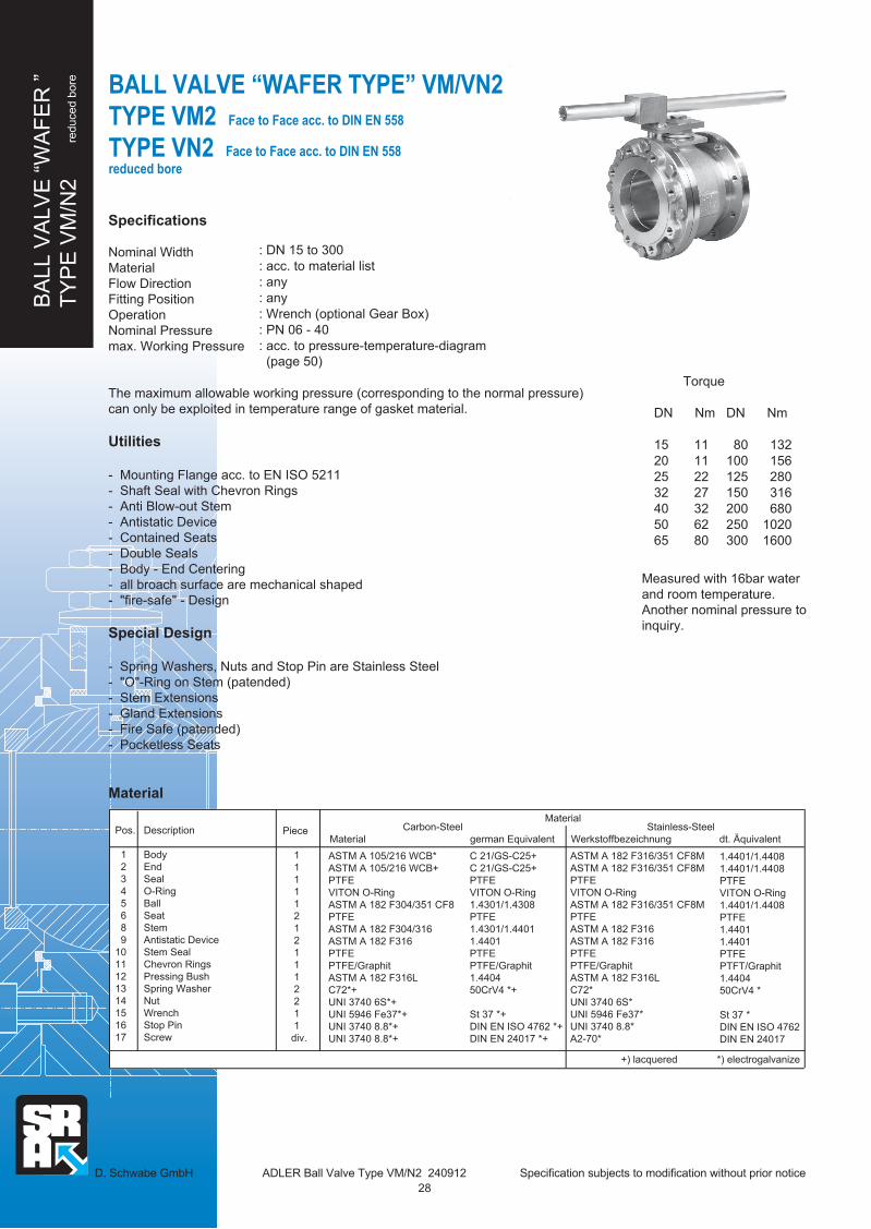
DN Nm
80 132100 156125 280150 316200 680250 1020300 1600
BA
LL V
ALV
E “
WA
FE
R ”
TY
PE
VM
/N2
reduce
d b
ore BALL VALVE “WAFER TYPE” VM/VN2
TYPE VM2 Face to Face acc. to DIN EN 558
TYPE VN2 reduced bore
Specifications
Nominal WidthMaterialFlow DirectionFitting PositionOperationNominal Pressuremax. Working Pressure
The maximum allowable working pressure (corresponding to the normal pressure)can only be exploited in temperature range of gasket material.
Utilities
- Mounting Flange acc. to EN ISO 5211- Shaft Seal with Chevron Rings- Anti Blow-out Stem- Antistatic Device- Contained Seats- Double Seals- Body - End Centering - all broach surface are mechanical shaped- "fire-safe" - Design
Special Design
- Spring Washers, Nuts and Stop Pin are Stainless Steel- "O"-Ring on Stem (patended)- Stem Extensions- Gland Extensions- Fire Safe (patended)- Pocketless Seats
Material
: DN 15 to 300: acc. to material list: any: any: Wrench (optional Gear Box): PN 06 - 40: acc. to pressure-temperature-diagram (page 50)
Pos.
1 2 3 4 5 6 8 91011121314151617
Description
BodyEndSealO-RingBallSeatStemAntistatic DeviceStem SealChevron RingsPressing BushSpring WasherNutWrenchStop PinScrew
Piece
1 1 1 1 1 2 1 2 1 1 1 2 2 1 1 div.
Carbon-SteelMaterial german Equivalent
D. Schwabe GmbH ADLER Ball Valve Type VM/N2 240912 Specification subjects to modification without prior notice
Face to Face acc. to DIN EN 558
ASTM A 105/216 WCB*ASTM A 105/216 WCB+PTFEVITON O-RingASTM A 182 F304/351 CF8PTFEASTM A 182 F304/316ASTM A 182 F316PTFEPTFE/GraphitASTM A 182 F316LC72*+UNI 3740 6S*+UNI 5946 Fe37*+UNI 3740 8.8*+UNI 3740 8.8*+
Material Stainless-SteelWerkstoffbezeichnung dt. Äquivalent
1.4401/1.4408 1.4401/1.4408 PTFE VITON O-Ring 1.4401/1.4408 PTFE 1.4401 1.4401 PTFE PTFT/Graphit 1.4404 50CrV4 *
St 37 * DIN EN ISO 4762 DIN EN 24017
+) lacquered *) electrogalvanize
C 21/GS-C25+C 21/GS-C25+PTFEVITON O-Ring1.4301/1.4308PTFE 1.4301/1.44011.4401PTFEPTFE/Graphit1.440450CrV4 *+
St 37 *+DIN EN ISO 4762 *+DIN EN 24017 *+
ASTM A 182 F316/351 CF8MASTM A 182 F316/351 CF8MPTFEVITON O-RingASTM A 182 F316/351 CF8MPTFEASTM A 182 F316ASTM A 182 F316PTFEPTFE/GraphitASTM A 182 F316LC72*UNI 3740 6S*UNI 5946 Fe37*UNI 3740 8.8*A2-70*
Torque
DN Nm
15 1120 1125 2232 2740 3250 6265 80
Measured with 16bar water and room temperature. Another nominal pressure toinquiry.
28

BA
LL V
ALV
E “
WA
FE
R ”
TY
PE
VM
/N2
reduced b
ore
D. Schwabe GmbH ADLER Ball Valve Type VM/N2 240912 Specification subjects to modification without prior notice
Face to Face acc. to DIN EN 558
Dimensions in mm
DN D
15
15
19
25
30
38
51
64
76
101
118
152
203
254
E
49
51,5
50
51,5
55
61
65
74
74
119
109
122
191
220
H
86
86
88
113
119
110
120
144
152
174
188
256
294
343
L
115
120
125
130
140
150
170
180
190
350
350
400
450
500
L1
130
150
160
180
200
230
290
310
350
480
480
600
730
850
N
58
58
58
58
37
60
62
74
74
82
98
139
140
166
O
35
35
35
35
34
45
46
62
62
80
98
128
140
160
S
6
6
6
8
8
10
10
14
14
18
18
28
32
36
Ød2
25
25
25
25
25
35
35
55
55
55
70
85
100
130
Ød3
36
36
36
36
36
50
50
70
70
70
102
125
140
165
d4
M5
M5
M5
M5
M5
M6
M6
M8
M8
M8
M10
M12
M16
M20
15 .. .. 20
25
32
40 50
65
80
100
125
150
200
250
300
Flange dimensions acc. with the respective ANSI-Norm *) difference weight in stainless steel device
F
6,6
6,6
8,2
8,2
16,5
19,5
19,5
23,5
23,5
26,5
26,5
34
36
44
h4
1,5
1,5
1,5
1,5
2
2
2
2
2
2
2
2
2
3
P
33,1
35,4
49,3
54,8
46,5
55
65
82
90,5
99,5
113
144
183
220
T
7
7
9,5
9,5
9,5
10
10
12
12
16,5
16,5
19
20
20
V
10
10
10
12
12
16
16
22
22
30
30
42
48
56
EN ISO
5211
F03
F03
F03
F03
F03
F05
F05
F07
F07
F07
F10
F12
F14
F16
Weight
VM2 (kg) VN2
3,0 3,1
4,0 4,1
5,2 5,4
7,0 7,3
9,0 13,0
11,9 17,0
16,6 21,6
19,6 32,0
25,0 40,0
76,6 100,0
72,6 95,0
114,0 140,0
160,0 220,0
220,0 250,0
M
145
145
145
185
185
280
280
370
370
470
650
750
900
1000
BALL VALVE “WAFER TYPE” VM/VN2
TYPE VM2 Face to Face acc. to DIN EN 558
TYPE VN2reduced bore
Ø D
L1
H
E
Flange Dimensions
acc. to DIN EN 1092-1
DN 200-300
DN 15-150
1415
16
1213
11
9
10
8
6
4
5
2
1
3 17
M
= VN2
M
H
L = VM2
V
h4
T ±1
F ±1
P
O
S
Ø d
3
Ø d
2
N
4 Mounting Holes d4
29

BALL VALVE “WAFER TYPE” TYPE VE/F2
TYPE VE2 Face to Face acc. to ISO 5752 S
TYPE VF2 Face to Face acc. to ISO 5752 M reduced bore
Specifications
Nominal Width
Material
Flow Direction
Fitting Position
Operation
Nominal Pressure
max. Working Pressure
The maximum allowable working pressure (corresponding to the normal pressure)
can only be exploited in temperature range of gasket material.
Utilities
- Mounting Flange acc. to EN ISO 5211
- Shaft Seal with Chevron Rings
- Anti Blow-out Stem
- Antistatic Device
- Contained Seats
- Double Seals
- Body - End Centering
- all broach surface are mechanical shaped
- "fire-safe" - Design
Special Design
- Spring Washers, Nuts and Stop Pin are Stainless Steel
- "O"-Ring on Stem (patended)
- Stem Extensions
- Gland Extensions
- Fire Safe (patended)
- Pocketless Seats
Material
: DN 1/2" to 12"
: acc. to material list
: any
: any
: Wrench (optional Gear Box)
: ANSI 150
: acc. to pressure-temperature-diagram
(page 50)
Pos.
1
2
3
4
5
6
8
9
10
11
12
13
14
15
16
17
Description
Body
End
Seal
O-Ring
Ball
Seat
Stem
Antistatic Device
Stem Seal
Chevron Rings
Pressing Bush
Spring Washer
Nut
Wrench
Stop Pin
Screw
Piece
1
1
1
1
1
2
1
2
1
1
1
2
2
1
1
div.
D. Schwabe GmbH ADLER Ball Valve Type VE/F2 240912 Specification subjects to modification without prior notice
DN Nm
3" 132
4" 156
5" 280
6" 316
8" 680
10" 1020
12" 1600
Torque
DN Nm
1/2" 11
3/4" 11
1" 22
1 1/4" 27
1 1/2" 32
2" 62
2 1/2" 80
Measured with 16bar water
and room temperature.
Another nominal pressure to
inquiry.
ASTM A 105/216 WCB+
ASTM A 105/216 WCB+
PTFE
VITON O-Ring
ASTM A 182 F304/351 CF8
PTFE
ASTM A 182 F304/316
ASTM A 182 F316
PTFE
PTFE/Graphit
ASTM A 182 F316L
C72*+
UNI 3740 6S*+
UNI 5946 Fe37*+
UNI 3740 8.8*+
UNI 3740 8.8*+
Carbon-Steel
Material german Equivalent
Material Stainless-Steel
Material german Equivalent
1.4401/1.4408
1.4401/1.4408
P.T.F.E.
VITON O-Ring
1.4401/1.4408
P.T.F.E.
1.4401
1.4401
P.T.F.E.
P.T.F.T./Graphit
1.4404
50CrV4 *
St 37 *
DIN 912-8.8
DIN EN 24017
+) lacquered *) electrogalvanize
C 21/GS-C25 +
C 21/GS-C25 +
P.T.F.E.
VITON O-Ring
1.4301/1.4308
P.T.F.E.
1.4301/1.4401
1.4401
P.T.F.E.
P.T.F.E./Graphit
1.4404
50CrV4 *+
St 37 *+
DIN 912-8.8 *+
DIN EN 24017 *+
ASTM A 182 F316/351 CF8M
ASTM A 182 F316/351 CF8M
PTFE
VITON O-Ring
ASTM A 182 F316/351 CF8M
PTFE
ASTM A 182 F316
ASTM A 182 F316
PTFE
PTFE/Graphit
ASTM A 182 F316L
C72*
UNI 3740 6S*
UNI 5946 Fe37*
UNI 3740 8.8*
A2-70
BA
LL V
ALV
E “
WA
FE
R ”
TY
PE
VE
/F2
reduced b
ore
30

BA
LL V
ALV
E “
WA
FE
R ”
TY
PE
VE
/F2
reduced b
ore
D. Schwabe GmbH ADLER Ball Valve Type VE/F2 240912 Specification subjects to modification without prior notic
Dimensions in mm
DN
1/2"
3/4"
1"
1 1/4"
1 1/2"
2"
2 1/2"
3"
4"
5"
6"
8"
10"
12"
D
15
15
19
25
30
38
51
64
76
101
118
152
203
254
E
46
48,5
49
52
78
82
88
107
109
171
157
160
135
158
H
86
86
88
113
119
110
120
144
152
174
188
256
256
294
L
108
117
127
140
165
178
190
203
229
267
267
292
330
356
L1
457
533
610
N
35
35
37
45
40
60
62
84
73
115
100
139
140
141
O
33
33
33
33
34
45
46
63
75
80
98
128
144
170
S
6
6
6
8
8
10
10
14
14
18
18
28
28
32
Ød2
25
25
25
25
25
35
35
55
55
55
70
85
85
100
Ød3
36
36
36
36
36
50
50
70
70
70
102
125
125
140
d4
M5
M5
M5
M5
M5
M6
M6
M8
M8
M8
M10
M12
M12
M16
.. ..
Flange dimensions acc. with the respective ANSI-Norm
F
7
7
7
16,5
16,5
19,5
19,5
23,5
23,5
26,5
26,5
34
34
26
h4
1,5
1,5
1,5
1,5
2
2
2
2
2
2
2
2
2
3
P
32,5
32,5
35
41
46,5
55
65
82
90,5
99,5
113
144
144
193
T
7
7
9,5
9,5
9,5
10
10
12
12
16,5
16,5
19
19
20
V
10
10
10
12
12
16
16
22
22
30
30
42
42
48
EN ISO
5211
F03
F03
F03
F03
F03
F05
F05
F07
F07
F07
F10
F12
F12
F14
Weight
VE2 (kg) VF2
2,7 3,6
3,6 3,6
4,5 5,0
6,2 6,5
7,7 8,0
12,0 10,0
17,0 13,0
20,0 19,0
32,8 27,0
55,7 40,0
52,6 72,0
85,0 80,0
145,0 125,0
210,0 180,0
M
145
145
145
185
185
280
280
370
370
470
650
750
900
1000
BALL VALVE “WAFER TYPE” TYPE VE/F2
TYPE VE2 Face to Face acc. to ISO 5752 S
TYPE VF2 Face to Face acc. to ISO 5752 M reduced bore
V
Ø D
O
N
Ø d
2
Ø d
3
S
L1
H
E
T ±1
4 Mounting Holes d4
F ±1 h4
DN 8"-12"
DN 1/2"-6"
15
16
14
13
12
10
9
5
6
8
11
4
3
2
1
17
M
= VF2
M
H
L = VE2
P
31

D. Schwabe GmbH ADLER Ball Valve Type VG2 240912 Specification subjects to modification without prior notice
BA
LL V
ALV
E “
WA
FE
R ”
TY
PE
VG
2 re
duced b
ore
BALL VALVE “WAFER TYPE” TYPE VG2
Face to Face acc. to ISO 5752 S reduced bore
Specifications
Nominal Width
Material
Flow Direction
Fitting Position
Operation
Nominal Pressure
max. Working Pressure
The maximum allowable working pressure (corresponding to the normal pressure)
can only be exploited in temperature range of gasket material.
Utilities
- Mounting Flange acc. to EN ISO 5211
- Shaft Seal with Chevron Rings
- Anti Blow-out Stem
- Antistatic Device
- Contained Seats
- Double Seals
- Body - End Centering
- all broach surface are mechanical shaped
- "fire-safe" - Design
Special Design
- Spring Washers, Nuts and Stop Pin are Stainless Steel
- "O"-Ring on Stem (patended)
- Stem Extensions
- Gland Extensions
- Fire Safe (patended)
- Pocketless Seats
Material
: DN 1/2" to 12"
: acc. to material list
: any
: any
: Wrench (optional Gear Box)
: ANSI 300
: acc. to pressure-temperature-diagram
(page 50)
Pos.
1
2
3
4
5
6
8
9
10
11
12
13
14
15
16
17
Description
Body
End
Seal
O-Ring
Ball
Seat
Stem
Antistatic Device
Stem Seal
Chevron Rings
Pressing Bush
Spring Washer
Nut
Wrench
Stop Pin
Screw
Piece
1
1
1
1
1
2
1
2
1
1
1
2
2
1
1
div.
Torque
DN Nm
1/2" 11
3/4" 11
1" 22
1 1/4" 27
1 1/2" 32
2" 62
2 1/2" 80
Measured with 16bar water
and room temperature.
Another nominal pressure to
inquiry.
DN Nm
3" 132
4" 156
5" 280
6" 316
8" 680
10" 1020
12" 1600
ASTM A 105/216 WCB+
ASTM A 105/216 WCB+
PTFE
VITON O-Ring
ASTM A 182 F304/351 CF8
PTFE
ASTM A 182 F304/316/6
ASTM A 182 F316
PTFE
PTFE/Graphit
ASTM A 182 F316L
C72*+
UNI 3740 6S*+
UNI 5946 Fe37*+
UNI 3740 8.8*+
UNI 3740 8.8*+
Carbon-Steel
Material german Equivalent
Material Stainless-Steel
Material german Equivalent
1.4401/1.4408
1.4401/1.4408
PTFE
VITON O-Ring
1.4401/1.4408
PTFE
1.4401
1.4401
PTFE
PTFT/Graphit
1.4404
50CrV4 *
St 37 *
DIN EN ISO 4762
DIN EN 24017
+) lacquered *) electrogalvanize
C 21+/GS-C25+
C 21+/GS-C25+
PTFE
VITON O-Ring
1.4301/1.4308
PTFE
1.4001/1.4301/1.4401
1.4401
PTFE
PTFE/Graphit
1.4404
50CrV4 *+
St 37 *+
DIN EN ISO 4762 *+
DIN EN 24017 *+
ASTM A 182 F316/351 CF8M
ASTM A 182 F316/351 CF8M
PTFE
VITON O-Ring
ASTM A 182 F316/351 CF8M
PTFE
ASTM A 182 F316
ASTM A 182 F316
PTFE
PTFE/Graphit
ASTM A 182 F316L
C72*
UNI 3740 6S*
UNI 5946 Fe37*
UNI 3740 8.8*
A2-70
32

BA
LL V
ALV
E “
WA
FE
R ”
TY
PE
VG
2 re
duced b
ore
BALL VALVE “WAFER TYPE” TYPE VG2
Face to Face acc. to ISO 5752 S reduced bore
D. Schwabe GmbH ADLER Ball Valve Type VG2 240912 Specification subjects to modification without prior notice
Dimensions in mm
DN
1/2"
3/4"
1"
1 1/4"
1 1/2"
2"
2 1/2"
3"
4"
5" *)
6"
8"
10"
12"
D
15
15
19
25
30
38
51
64
76
101
118
152
203
254
E
57,5
58,5
59,5
71
78
82
88
107
109
171
157
160
135
158
H
86
88
113
119
119
110
120
144
152
174
188
256
256
294
L
140
151
165
178
191
216
241
283
305
403
403
419
457
N
35
35
37
45
40
60
62
84
73
115
100
139
140
141
O
33
33
33
33
34
45
46
63
75
80
98
128
144
170
S
6
6
6
8
8
10
10
14
14
18
18
28
28
32
Ød2
25
25
25
25
25
35
35
55
55
55
70
85
85
100
Ød3
36
36
36
36
36
50
50
70
70
70
102
125
125
140
d4
M5
M5
M5
M5
M5
M6
M6
M8
M8
M8
M10
M12
M12
M16
.. ..
Flange dimensions acc. with the respective ANSI-Norm
*) EXCEPTION: ball valve specified with RG2
F
7,5
7,5
16,5
16,5
16,5
19,5
19,5
23,5
23,5
26,5
26,5
34
34
26
h4
1,5
1,5
1,5
1,5
2
2
2
2
2
2
2
2
2
3
P
32,5
32,5
35
41
46,5
55
65
82
90,5
99,5
113
144
144
193
T
7,5
7,5
7,5
9,5
9,5
10
10
12
12
16,5
16,5
19
19
20
V
10
10
10
12
12
16
16
22
22
30
30
42
42
48
EN ISO
5211
F03
F03
F03
F03
F03
F05
F05
F07
F07
F07
F10
F12
F12
F14
Weight
(kg)
2,7
3,6
4,5
6,2
7,7
12,0
17,0
20,0
32,8
55,7
52,6
85,0
145,0
210,0
M
145
145
145
185
185
280
280
370
370
470
650
750
900
1000
Ø D
V
O
S
Ø d
3
Ø d
2
N
H
E
h4
T ±1
F ±1
4 Mounting Holes d4
DN 1/2"-6"
DN 8"-12"
1514
13
1112
10
9
16
6
5
4
3
2
1
8
17
M
M
H
L P
33

1.4401/1.4408
1.4401/1.4408
P.T.F.E.
VITON O-Ring
1.4401/1.4408
P.T.F.E.
1.4401
1.4401
P.T.F.E.
P.T.F.T./Graphit
1.4404
50CrV4 *
St 37 *
DIN 912-8.8
Specifications
Nominal Width
Material
Flow Direction
Fitting Position
Operation
Nominal Pressure
max. Working Pressure
The maximum allowable working pressure (corresponding to the normal pressure)
can only be exploited in temperature range of gasket material.
Utilities
- Mounting Flange Dimensions acc. to EN ISO 5211
- Shaft Seal with Chevron Rings
- Anti-Blow-Out Stem
- Antistatic Device
- Contents Ball
- Metal Beating Ring
- Double Seals
- All broach surfaces are mechanical shaped
- "Fire-Safe" - Design
Special Design
- Spring Washers, Nuts and Stop Pin are Stainless Steel
- "O"-Ring on Stem (patended)
- Stem Extensions
- Gland Extensions
- Fire Safe (patended)
Material
: DN 40 bis 200
: acc. to material list
: any
: any
: Wrench
: PN 10 to16 or ANSI 150
: acc. to pressure-temperature-diagram
(page 50)
D. Schwabe GmbH ADLER Ball Valve Type FU4 290813 Specification Subject To Modification Without Prior Notice
BALL VALVE “3 WAY WAFER” 120°
TYPE FU4 full bore
Pos.
1
2
3
4
5
6
8
9
10
11
12
13
14
15
16
Description
Body
Insert
Seal
O-Ring
Ball
Seat
Stem
Antistatic Device
Stem Seal
Chevron Rings
Pressing Bush
Spring Washer
Nut
Wrench
Stop Pin
Piece
1
3
3
3
1
2
1
2
1
1
1
2
2
1
1
ASTM A 105+
ASTM A 105+
PTFE
VITON O-Ring
ASTM A 182 F304/351 CF8
PTFE
ASTM A 182 F6/304/316
ASTM A 182 F316
PTFE
PTFE/Graphit
ASTM A 182 F316L
C72*+
UNI 3740 6S*+
UNI 5946 Fe37*+
UNI 3740 8.8*+
Carbon Steel
Material german Equivalent
DN Nm
65 191
80 226
100 410
125 460
150 986
200 1480
Torque
DN Nm
10 15
15 16
20 32
25 40
32 46
40 90
50 116
Measured with 16bar water
and room temperature.
Another nominal pressure
to inquiry.
Description Stainless Steel
Material german Equivalent
+)varnish paint coat *) electroplated zinc coating
C 21 +
C 21 +
PTFE
VITON O-Ring
1.4301/1.4308
PTFE
1.4001/1.4301/1.4401
1.4401
PTFE
PTFE/Graphit
1.4404
50CrV4 *+
St 37 *+
DIN 912-8.8 *+
ASTM A 182 F316/351 CF8M
ASTM A 182 F316/351 CF8M
PTFE
VITON O-Ring
ASTM A 182 F316/351 CF8M
PTFE
ASTM A 182 F316
ASTM A 182 F316
PTFE
PTFE/Graphit
ASTM A 182 F316L
C72*
UNI 3740 6S*
UNI 5946 Fe37*
UNI 3740 8.8*
BA
LL V
ALV
E “
3 W
AY
”
TY
PE
FU
4
34
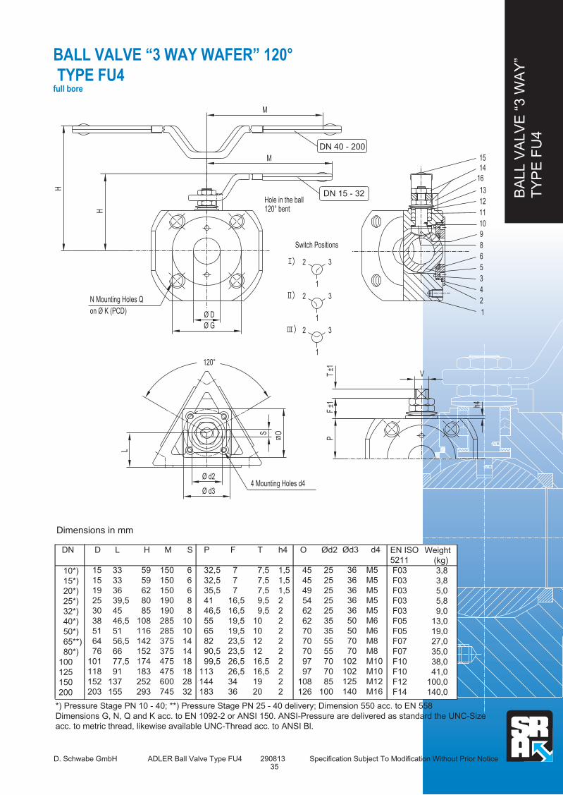
BA
LL V
ALV
E “
3 W
AY
”
TY
PE
FU
4
D. Schwabe GmbH ADLER Ball Valve Type FU4 290813 Specification Subject To Modification Without Prior Notice
BALL VALVE “3 WAY WAFER” 120°
TYPE FU4 full bore
Dimensions in mm
DN D
15
15
19
25
30
38
51
64
76
101
118
152
203
H
59
59
62
80
85
108
116
142
152
174
183
252
293
L
33
33
36
39,5
45
46,5
51
56,5
66
77,5
91
137
155
P
32,5
32,5
35,5
41
46,5
55
65
82
90,5
99,5
113
144
183
F
7
7
7
16,5
16,5
19,5
19,5
23,5
23,5
26,5
26,5
34
36
T
7,5
7,5
7,5
9,5
9,5
10
10
12
12
16,5
16,5
19
20
Ød2
25
25
25
25
25
35
35
55
55
70
70
85
100
Ød3
36
36
36
36
36
50
50
70
70
102
102
125
140
d4
M5
M5
M5
M5
M5
M6
M6
M8
M8
M10
M10
M12
M16
10*)
15*)
20*)
25*)
32*)
40*)
50*)
65**)
80*)
100
125
150
200
.. ..
*) Pressure Stage PN 10 - 40; **) Pressure Stage PN 25 - 40 delivery; Dimension 550 acc. to EN 558
Dimensions G, N, Q and K acc. to EN 1092-2 or ANSI 150. ANSI-Pressure are delivered as standard the UNC-Size
acc. to metric thread, likewise available UNC-Thread acc. to ANSI Bl.
O
45
45
49
54
62
62
70
70
70
97
97
108
126
h4
1,5
1,5
1,5
2
2
2
2
2
2
2
2
2
2
EN ISO
5211
F03
F03
F03
F03
F03
F05
F05
F07
F07
F10
F10
F12
F14
Weight
(kg)
3,8
3,8
5,0
5,8
9,0
13,0
19,0
27,0
35,0
38,0
41,0
100,0
140,0
S
6
6
6
8
8
10
10
14
14
18
18
28
32
h4
VT ±1
F ±1
P
15
14
16
13
12
10
9
11
6
5
3
2
4
1
8
3
3
1
2
2
3
1
1
2
Switch Positions
Hole in the ball120° bent
DN 15 - 32
DN 40 - 200
M
M
Ø D
Ø G
H
H
on Ø K (PCD)
N Mounting Holes Q
O
120°
S
Ø d3
Ø d2
L
4 Mounting Holes d4
M
150
150
150
190
190
285
285
375
375
475
475
600
745
35
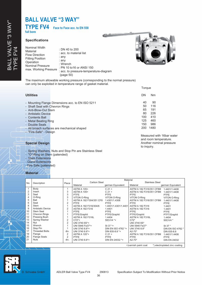
BA
LL V
ALV
E “
3 W
AY
”
TY
PE
FV
4
Specifications
Nominal Width
Material
Flow Direction
Fitting Position
Operation
Nominal Pressure
max. Working Pressure
The maximum allowable working pressure (corresponding to the normal pressure)
can only be exploited in temperature range of gasket material.
Utilities
- Mounting Flange Dimensions acc. to EN ISO 5211
- Shaft Seal with Chevron Rings
- Anti-Blow-Out Stem
- Antistatic Device
- Contents Ball
- Metal Beating Ring
- Double Seals
- All broach surfaces are mechanical shaped
- "Fire-Safe" - Design
Special Design
- Spring Washers, Nuts and Stop Pin are Stainless Steel
- "O"-Ring on Stem (patended)
- Stem Extensions
- Gland Extensions
- Fire Safe (patended)
Material
: DN 40 to 200
: acc. to material list
: any
: any
: Wrench
: PN 10 to16 or ANSI 150
: acc. to pressure-temperature-diagram
(page 50)
D. Schwabe GmbH ADLER Ball Valve Type FV4 290813 Specification Subject To Modification Without Prior Notice
BALL VALVE “3 WAY”
TYPE FV4 Face to Face acc. to EN 558 full bore
Torque
DN Nm
40 90
50 116
65 191
80 226
100 410
125 460
150 986
200 1480
Measured with 16bar water
and room temperature.
Another nominal pressure
to inquiry.
No.
1
2
3
4
5
6
8
9
10
11
12
13
14
15
16
17
19
20
21
Description
Body
Insert
Seal
O-Ring
Ball
Seat
Stem
Antistatic Device
Stem Seal
Chevron Rings
Pressing Bush
Spring Washer
Nut
Wrench
Stop Pin
Threaded Bolts
Flange
Flange Seals
Nuts
Piece
1
3
3
3
1
2
1
2
1
1
1
2
2
1
1
div.
2
2
div.
ASTM A 105+
ASTM A 105+
PTFE
VITON O-Ring
ASTM A 182 F304/351 CF8
PTFE
ASTM A 182 F316/304/6
ASTM A 182 F316
PTFE
PTFE/Graphit
ASTM A 182 F316L
C72*+
UNI 3740 6S*+
UNI 5946 Fe37*+
UNI 3740 8.8*+
UNI 3740 8.8*+
ASTM A 105*+
PTFE
UNI 3740 8.8*+
Carbon Steel
Material german Equivalent
Stainless Steel
Material german Equivalent
1.4401/1.4408
1.4401/1.4408
PTFE
VITON O-Ring
1.4401/1.4408
PTFE
1.4401
1.4401
PTFE
PTFT/Graphit
1.4404
50CrV4 *
St 37 *
DIN EN ISO 4762 *
DIN 835-8.8
1.4401/1.4408
PTFE
DIN EN 24032
+)varnish paint coat *) electroplated zinc coating
C 21 +
C 21 +
PTFE
VITON O-Ring
1.4301/1.4308
PTFE
1.4001/1.4301/1.4401
1.4401
PTFE
PTFE/Graphit
1.4404
50CrV4 *+
St 37 *+
DIN EN ISO 4762 *+
DIN 835-8.8 *+
C 21 +
PTFE
DIN EN 24032 *+
ASTM A 182 F316/351 CF8M
ASTM A 182 F316/351 CF8M
PTFE
VITON O-Ring
ASTM A 182 F316/351 CF8M
PTFE
ASTM A 182 F316
ASTM A 182 F316
PTFE
PTFE/Graphit
ASTM A 182 F316L
C72*
UNI 3740 6S*
UNI 5946 Fe37*
UNI 3740 8.8*
A2-70*
ASTM A 182 F316/351 CF8M
PTFE
A2-70*
Material
36

BA
LL V
ALV
E “
3 W
AY
”
TY
PE
FV
4
BALL VALVE “3 WAY”
TYPE FV4 ace to Face acc. to EN 558 full bore
D. Schwabe GmbH ADLER Ball Valve Type FV4 290813 Specification Subject To Modification Without Prior Notice
Dimensions in mm
DN D
38
51
64
76
101
118
152
203
H
108
116
142
152
174
183
252
293
L
200
230
290
310
350
400
550**)
600
P
55
65
82
90,5
99,5
113
144
183
F
19,5
19,5
23,5
23,5
26,5
26,5
34
36
T
10
10
12
12
16,5
16,5
19
20
Ød2
35
35
55
55
70
70
85
100
Ød3
50
50
70
70
102
102
125
140
d4
M6
M6
M8
M8
M10
M10
M12
M16
40*)
50*)
65**)
80*)
100
125
150
200
.. ..
*) Pressure Stage PN 10 - 40; **) Pressure Stage PN 25 - 40 delivery; Dimension 550 acc. to EN 558
Dimensions G, N, Q and K acc. to EN 1092-2 or ANSI 150. ANSI-Pressure are delivered as standard the UNC-Size
acc. to metric thread, likewise available UNC-Thread acc. to ANSI Bl.
O
62
70
70
70
97
97
108
126
h4
2
2
2
2
2
2
2
2
EN ISO
5211
F05
F05
F07
F07
F10
F10
F12
F14
Weight
(kg)
16,0
23,0
31,0
40,0
50,0
60,0
125,0
180,0
S
10
10
14
14
18
18
28
32
M
285
285
375
375
475
475
600
745
h4
VT ±1
F ±1
P
3
3
1
3
1
2
2
2
Switch Positions
1
15
Ø D
1on Ø K (PCD)N Mounting Holes Q
16
9
6
5
8
11
4
2
3
1
14
13
12
10
DN 40-200
H
Ø D
Ø G
L
M
O
S
Ø d2
Ø d3
1/2
L
Bore (in the ball)120° bent 19
17
20
21
4 Mounting Holes d4
37
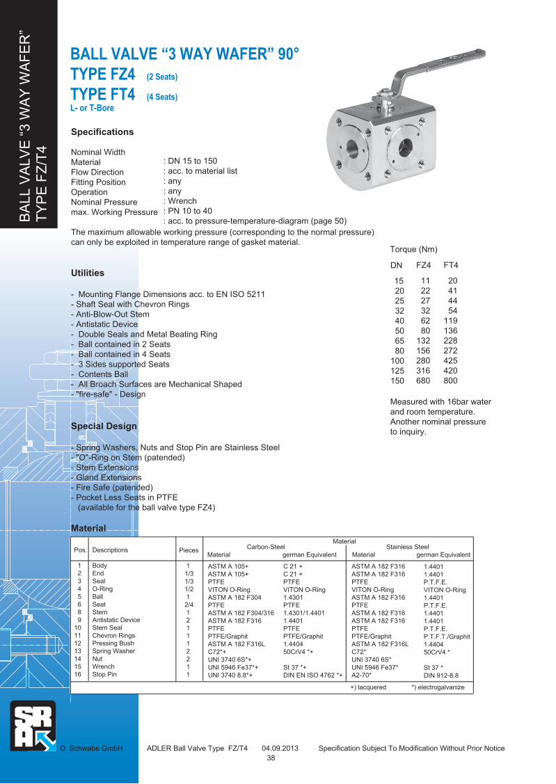
BA
LL V
ALV
E “
3 W
AY
WA
FE
R”
TY
PE
FZ
/T4
: DN 15 to 150
: acc. to material list
: any
: any
: Wrench
: PN 10 to 40
: acc. to pressure-temperature-diagram (page 50)
BALL VALVE “3 WAY WAFER” 90°
TYPE FZ4 (2 Seats)
TYPE FT4 (4 Seats)
L- or T-Bore
D. Schwabe GmbH ADLER Ball Valve Type FZ/T4 04.09.2013 Specification Subject To Modification Without Prior Notice
Measured with 16bar water
and room temperature.
Another nominal pressure
to inquiry.
DN
15
20
25
32
40
50
65
80
100
125
150
FZ4
11
22
27
32
62
80
132
156
280
316
680
FT4
20
41
44
54
119
136
228
272
425
420
800
Torque (Nm)
Specifications
Nominal Width
Material
Flow Direction
Fitting Position
Operation
Nominal Pressure
max. Working Pressure
The maximum allowable working pressure (corresponding to the normal pressure)
can only be exploited in temperature range of gasket material.
Utilities
- Mounting Flange Dimensions acc. to EN ISO 5211
- Shaft Seal with Chevron Rings
- Anti-Blow-Out Stem
- Antistatic Device
- Double Seals and Metal Beating Ring
- Ball contained in 2 Seats
- Ball contained in 4 Seats
- 3 Sides supported Seats
- Contents Ball
- All Broach Surfaces are Mechanical Shaped
- "fire-safe" - Design
Special Design
- Spring Washers, Nuts and Stop Pin are Stainless Steel
- "O"-Ring on Stem (patended)
- Stem Extensions
- Gland Extensions
- Fire Safe (patended)
- Pocket Less Seats in PTFE
(available for the ball valve type FZ4)
Material
Pos.
1
2
3
4
5
6
8
9
10
11
12
13
14
15
16
Descriptions
Body
End
Seal
O-Ring
Ball
Seat
Stem
Antistatic Device
Stem Seal
Chevron Rings
Pressing Bush
Spring Washer
Nut
Wrench
Stop Pin
Pieces
1
1/3
1/3
1/2
1
2/4
1
2
1
1
1
2
2
1
1
ASTM A 105+
ASTM A 105+
PTFE
VITON O-Ring
ASTM A 182 F304
PTFE
ASTM A 182 F304/316
ASTM A 182 F316
PTFE
PTFE/Graphit
ASTM A 182 F316L
C72*+
UNI 3740 6S*+
UNI 5946 Fe37*+
UNI 3740 8.8*+
Stainless Steel
Material german Equivalent
1.4401
1.4401
P.T.F.E.
VITON O-Ring
1.4401
P.T.F.E.
1.4401
1.4401
P.T.F.E.
P.T.F.T./Graphit
1.4404
50CrV4 *
St 37 *
DIN 912-8.8
Carbon-Steel
Material german Equivalent
Material
+) lacquered *) electrogalvanize
C 21 +
C 21 +
PTFE
VITON O-Ring
1.4301
PTFE
1.4301/1.4401
1.4401
PTFE
PTFE/Graphit
1.4404
50CrV4 *+
St 37 *+
DIN EN ISO 4762 *+
ASTM A 182 F316
ASTM A 182 F316
PTFE
VITON O-Ring
ASTM A 182 F316
PTFE
ASTM A 182 F316
ASTM A 182 F316
PTFE
PTFE/Graphit
ASTM A 182 F316L
C72*
UNI 3740 6S*
UNI 5946 Fe37*
A2-70*
38
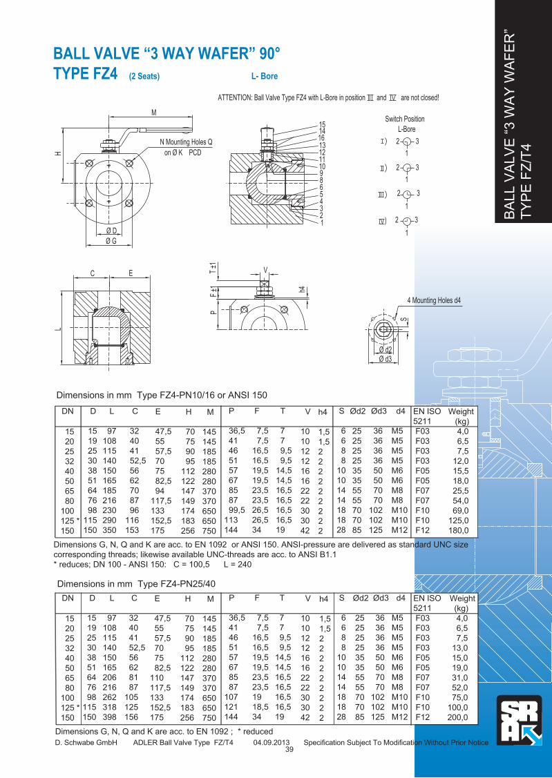
BA
LL V
ALV
E “
3 W
AY
WA
FE
R”
TY
PE
FZ
/T4
BALL VALVE “3 WAY WAFER” 90°
TYPE FZ4 (2 Seats) L- Bore
D. Schwabe GmbH ADLER Ball Valve Type FZ/T4 04.09.2013 Specification Subject To Modification Without Prior Notice
Dimensions in mm Type FZ4-PN10/16 or ANSI 150
DN D
15
19
25
30
38
51
64
76
98
115
150
C
32
40
41
52,5
56
62
70
87
96
116
153
L
97
108
115
140
150
165
185
216
230
290
350
P
36,5
41
46
51
57
67
85
87
99,5
113
144
F
7,5
7,5
16,5
16,5
19,5
19,5
23,5
23,5
26,5
26,5
34
T
7
7
9,5
9,5
14,5
14,5
16,5
16,5
16,5
16,5
19
Ød2
25
25
25
25
35
35
55
55
70
70
85
Ød3
36
36
36
36
50
50
70
70
102
102
125
d4
M5
M5
M5
M5
M6
M6
M8
M8
M10
M10
M12
15
20
25
32
40
50
65
80
100
125 *
150
.. ..
Dimensions G, N, Q and K are acc. to EN 1092 or ANSI 150. ANSI-pressure are delivered as standard UNC size
corresponding threads; likewise available UNC-threads are acc. to ANSI B1.1
* reduces; DN 100 - ANSI 150: C = 100,5 L = 240
S
6
6
8
8
10
10
14
14
18
18
28
h4
1,5
1,5
2
2
2
2
2
2
2
2
2
EN ISO
5211
F03
F03
F03
F03
F05
F05
F07
F07
F10
F10
F12
Weight
(kg)
4,0
6,5
7,5
12,0
15,5
18,0
25,5
54,0
69,0
125,0
180,0
E
47,5
55
57,5
70
75
82,5
94
117,5
133
152,5
175
M
V
h4
S
Ø d2Ø d3
PF
±1T
±1
on Ø K PCDH
Ø D
Ø G
EC
L
N Mounting Holes Q
L-Bore1514
16
12
10 9
11
8 6
4 5
2 1
3
13
ATTENTION: Ball Valve Type FZ4 with L-Bore in position and are not closed!
4 Mounting Holes d4
32
1
Switch Position
3
3
1
2
2
1
1
2 3
V
10
10
12
12
16
16
22
22
30
30
42
H
70
75
90
95
112
122
147
149
174
183
256
M
145
145
185
185
280
280
370
370
650
650
750
Dimensions in mm Type FZ4-PN25/40
DN D
15
19
25
30
38
51
64
76
98
115
150
C
32
40
41
52,5
56
62
81
87
105
125
156
L
97
108
115
140
150
165
206
216
262
318
398
P
36,5
41
46
51
57
67
85
87
107
121
144
F
7,5
7,5
16,5
16,5
19,5
19,5
23,5
23,5
19
18,5
34
T
7
7
9,5
9,5
14,5
14,5
16,5
16,5
16,5
16,5
19
Ød2
25
25
25
25
35
35
55
55
70
70
85
Ød3
36
36
36
36
50
50
70
70
102
102
125
d4
M5
M5
M5
M5
M6
M6
M8
M8
M10
M10
M12
15
20
25
32
40
50
65
80
100
125 *
150
.. ..
Dimensions G, N, Q and K are acc. to EN 1092 ; * reduced
S
6
6
8
8
10
10
14
14
18
18
28
h4
1,5
1,5
2
2
2
2
2
2
2
2
2
EN ISO
5211
F03
F03
F03
F03
F05
F05
F07
F07
F10
F10
F12
Weight
(kg)
4,0
6,5
7,5
13,0
15,0
19,0
31,0
52,0
75,0
100,0
200,0
E
47,5
55
57,5
70
75
82,5
110
117,5
133
152,5
175
V
10
10
12
12
16
16
22
22
30
30
42
H
70
75
90
95
112
122
147
149
174
183
256
M
145
145
185
185
280
280
370
370
650
650
750
39

BA
LL V
ALV
E “
3 W
AY
WA
FE
R”
TY
PE
FZ
/T4
D. Schwabe GmbH ADLER Ball Valve Type FZ/T4 04.09.2013 Specification Subject To Modification Without Prior Notice
Dimensions in mm Type FT4-PN10/16 or ANSI 150
DN D
15
19
25
30
38
51
64
69
87
108
136
C
32
40
41
52,5
56
62
70
87
96
116
180
L
97
108
115
140
150
165
185
216
230
290
370
P
36,5
41
46
51
57
67
85
87
99,5
113
144
F
7,5
7,5
16,5
16,5
19,5
19,5
23,5
23,5
26,5
26,5
34
T
7
7
9,5
9,5
14,5
14,5
16,5
16,5
16,5
16,5
19
Ød2
25
25
25
25
35
35
55
55
70
70
85
Ød3
36
36
36
36
50
50
70
70
102
102
125
d4
M5
M5
M5
M5
M6
M6
M8
M8
M10
M10
M12
15
20
25
32
40
50
65
80 *
100 *
125 *
150 *
.. ..
Dimensions G, N, Q and K are acc. to EN 1092 or ANSI 150. ANSI-pressure are delivered as standard UNC size
corresponding threads; likewise available UNC-threads are acc. to ANSI B1.1
* reduces; DN 100 - ANSI 150: C = 100,5 L = 240
S
6
6
8
8
10
10
14
14
18
18
28
h4
1,5
1,5
2
2
2
2
2
2
2
2
2
EN ISO
5211
F03
F03
F03
F03
F05
F05
F07
F07
F10
F10
F12
Weight
(kg)
4,0
6,5
7,5
12,0
15,5
18,0
25,5
54,0
69,0
125,0
200,0
E
47,5
55
57,5
70
75
82,5
94
117,5
133
152,5
175
V
10
10
12
12
16
16
22
22
30
30
42
H
70
75
90
95
112
122
147
149
174
183
256
M
145
145
185
185
280
280
370
370
650
650
750
Dimensions in mm Type FT4-PN25/40
DN D
15
19
25
30
38
51
64
69
87
108
C
32
40
41
52
56
62
81
87
105
125
L
97
108
115
140
150
165
206
216
262
318
P
36,5
41
46
51
57
67
85
87
107
121
F
7,0
7,0
16,5
16,5
19,5
19,5
23,5
23,5
19,0
18,5
T
7,5
7,5
9,5
9,5
14,5
14,5
16,5
16,5
16,5
16,5
Ød2
25
25
25
25
35
35
55
55
70
70
Ød3
36
36
36
36
50
50
70
70
102
102
d4
M5
M5
M5
M5
M6
M6
M8
M8
M10
M10
15
20
25
32
40
50
65
80 *
100 *
125 *
.. ..
Dimensions G, N, Q and K are acc. to EN 1092 ; * reduced
S
6
6
8
8
10
10
14
14
18
18
h4
1,5
1,5
2
2
2
2
2
2
2
2
EN ISO
5211
F03
F03
F03
F03
F05
F05
F07
F07
F10
F10
Weight
(kg)
4,0
6,0
7,5
13,0
15,0
19,0
31,0
52,0
75,0
100,0
E
47,5
55
57,5
70
75
82,5
110
117,5
133
152,5
V
10
10
12
12
16
16
22
22
30
30
H
70
75
90
95
112
122
147
149
174
183
M
145
145
185
185
280
280
370
370
650
650
BALL VALVE “3 WAY WAFER” 90°
TYPE FT4 (4 Seats) L- or T-Bore
G
M
h4
F ±1
T ±1
V
P
H
Ø D
on Ø K PCD
S
Ø d3
Ø d2
EC
L
N Mounting Holes Q
T-Bore L-Bore15
1614
12
91011
6 8
5 4
2 1
3
13
4 Mounting Holes d4
Switch Position
32
1
3
1
2
1
32
1
2 3
32
1
3
1
11
2
2 3 32
40
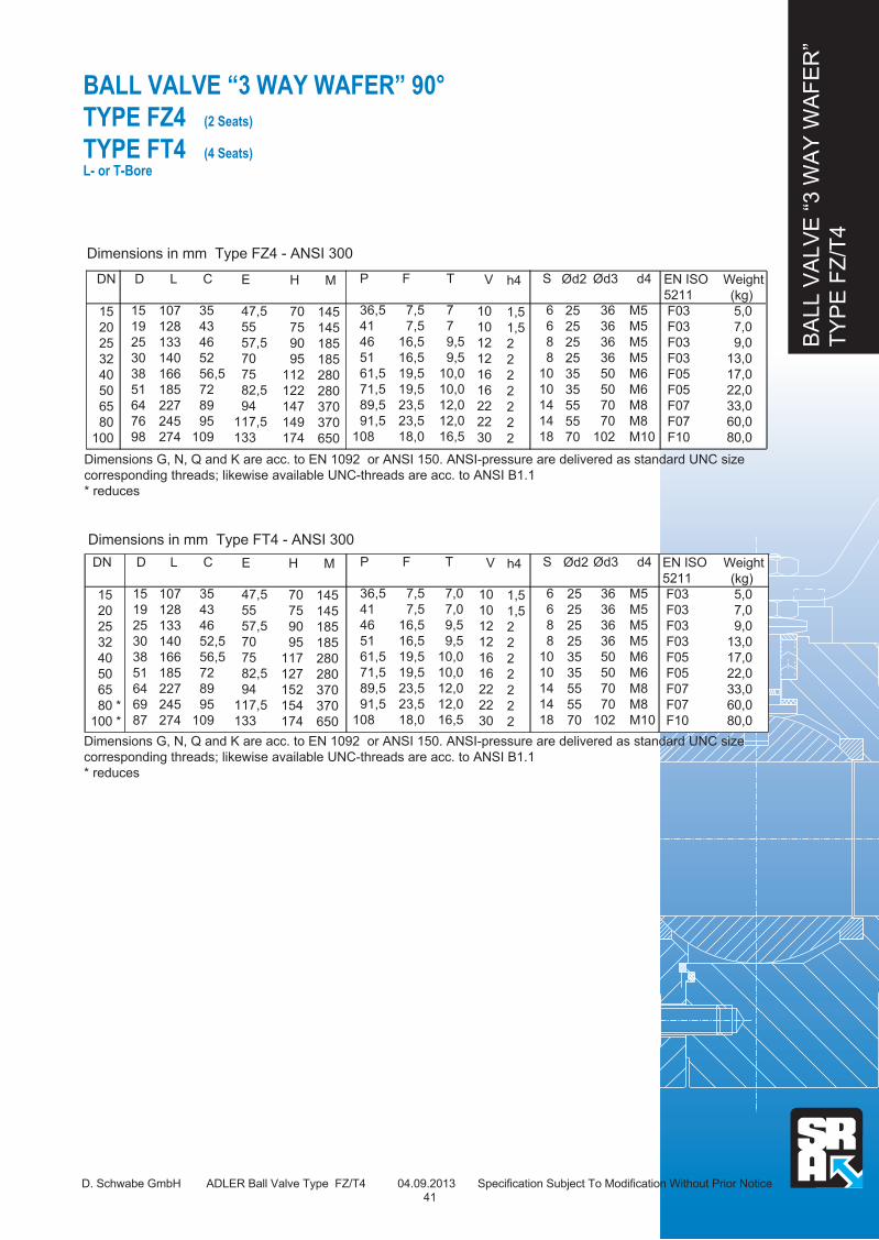
BA
LL V
ALV
E “
3 W
AY
WA
FE
R”
TY
PE
FZ
/T4
BALL VALVE “3 WAY WAFER” 90°
TYPE FZ4 (2 Seats)
TYPE FT4 (4 Seats)
L- or T-Bore
D. Schwabe GmbH ADLER Ball Valve Type FZ/T4 04.09.2013 Specification Subject To Modification Without Prior Notice
Dimensions in mm Type FZ4 - ANSI 300
DN D
15
19
25
30
38
51
64
76
98
C
35
43
46
52
56,5
72
89
95
109
L
107
128
133
140
166
185
227
245
274
P
36,5
41
46
51
61,5
71,5
89,5
91,5
108
F
7,5
7,5
16,5
16,5
19,5
19,5
23,5
23,5
18,0
T
7
7
9,5
9,5
10,0
10,0
12,0
12,0
16,5
Ød2
25
25
25
25
35
35
55
55
70
Ød3
36
36
36
36
50
50
70
70
102
d4
M5
M5
M5
M5
M6
M6
M8
M8
M10
15
20
25
32
40
50
65
80
100
.. ..
Dimensions G, N, Q and K are acc. to EN 1092 or ANSI 150. ANSI-pressure are delivered as standard UNC size
corresponding threads; likewise available UNC-threads are acc. to ANSI B1.1
* reduces
S
6
6
8
8
10
10
14
14
18
h4
1,5
1,5
2
2
2
2
2
2
2
EN ISO
5211
F03
F03
F03
F03
F05
F05
F07
F07
F10
Weight
(kg)
5,0
7,0
9,0
13,0
17,0
22,0
33,0
60,0
80,0
E
47,5
55
57,5
70
75
82,5
94
117,5
133
V
10
10
12
12
16
16
22
22
30
H
70
75
90
95
112
122
147
149
174
M
145
145
185
185
280
280
370
370
650
Dimensions in mm Type FT4 - ANSI 300
DN D
15
19
25
30
38
51
64
69
87
C
35
43
46
52,5
56,5
72
89
95
109
L
107
128
133
140
166
185
227
245
274
P
36,5
41
46
51
61,5
71,5
89,5
91,5
108
F
7,5
7,5
16,5
16,5
19,5
19,5
23,5
23,5
18,0
T
7,0
7,0
9,5
9,5
10,0
10,0
12,0
12,0
16,5
Ød2
25
25
25
25
35
35
55
55
70
Ød3
36
36
36
36
50
50
70
70
102
d4
M5
M5
M5
M5
M6
M6
M8
M8
M10
15
20
25
32
40
50
65
80 *
100 *
.. ..
Dimensions G, N, Q and K are acc. to EN 1092 or ANSI 150. ANSI-pressure are delivered as standard UNC size
corresponding threads; likewise available UNC-threads are acc. to ANSI B1.1
* reduces
S
6
6
8
8
10
10
14
14
18
h4
1,5
1,5
2
2
2
2
2
2
2
EN ISO
5211
F03
F03
F03
F03
F05
F05
F07
F07
F10
Weight
(kg)
5,0
7,0
9,0
13,0
17,0
22,0
33,0
60,0
80,0
E
47,5
55
57,5
70
75
82,5
94
117,5
133
V
10
10
12
12
16
16
22
22
30
H
70
75
90
95
117
127
152
154
174
M
145
145
185
185
280
280
370
370
650
41
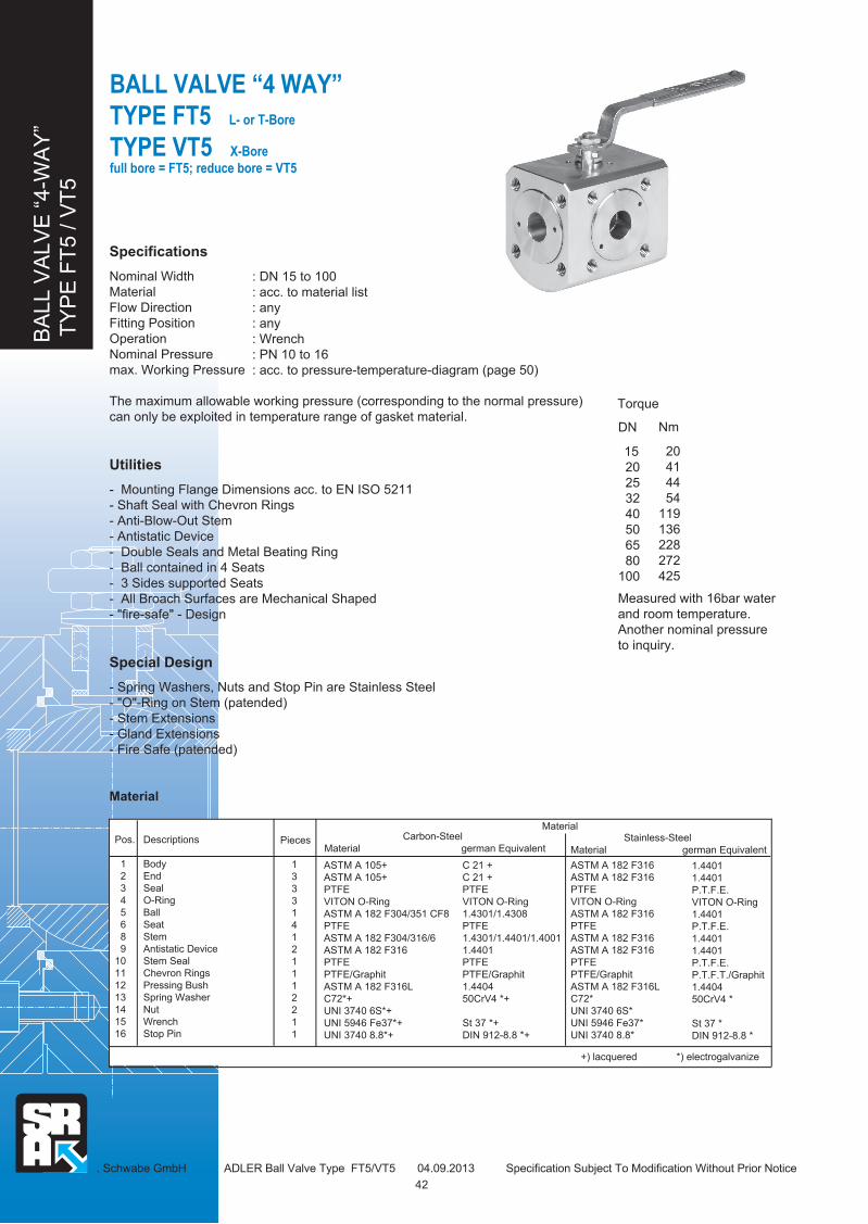
BA
LL V
ALV
E “
4-W
AY
”
TY
PE
FT
5 / V
T5
BALL VALVE “4 WAY”
TYPE FT5 L- or T-Bore
TYPE VT5 X-Bore
full bore = FT5; reduce bore = VT5
Measured with 16bar water
and room temperature.
Another nominal pressure
to inquiry.
. Schwabe GmbH ADLER Ball Valve Type FT5/VT5 04.09.2013 Specification Subject To Modification Without Prior Notice
DN
15
20
25
32
40
50
65
80
100
Nm
20
41
44
54
119
136
228
272
425
Torque
Specifications
Nominal Width
Material
Flow Direction
Fitting Position
Operation
Nominal Pressure
max. Working Pressure
The maximum allowable working pressure (corresponding to the normal pressure)
can only be exploited in temperature range of gasket material.
Utilities
- Mounting Flange Dimensions acc. to EN ISO 5211
- Shaft Seal with Chevron Rings
- Anti-Blow-Out Stem
- Antistatic Device
- Double Seals and Metal Beating Ring
- Ball contained in 4 Seats
- 3 Sides supported Seats
- All Broach Surfaces are Mechanical Shaped
- "fire-safe" - Design
Special Design
- Spring Washers, Nuts and Stop Pin are Stainless Steel
- "O"-Ring on Stem (patended)
- Stem Extensions
- Gland Extensions
- Fire Safe (patended)
Material
: DN 15 to 100
: acc. to material list
: any
: any
: Wrench
: PN 10 to 16
: acc. to pressure-temperature-diagram (page 50)
Pos.
1
2
3
4
5
6
8
9
10
11
12
13
14
15
16
Descriptions
Body
End
Seal
O-Ring
Ball
Seat
Stem
Antistatic Device
Stem Seal
Chevron Rings
Pressing Bush
Spring Washer
Nut
Wrench
Stop Pin
Pieces
1
3
3
3
1
4
1
2
1
1
1
2
2
1
1
ASTM A 105+
ASTM A 105+
PTFE
VITON O-Ring
ASTM A 182 F304/351 CF8
PTFE
ASTM A 182 F304/316/6
ASTM A 182 F316
PTFE
PTFE/Graphit
ASTM A 182 F316L
C72*+
UNI 3740 6S*+
UNI 5946 Fe37*+
UNI 3740 8.8*+
Carbon-Steel
Material german Equivalent Stainless-Steel
Material german Equivalent
+) lacquered *) electrogalvanize
C 21 +
C 21 +
PTFE
VITON O-Ring
1.4301/1.4308
PTFE
1.4301/1.4401/1.4001
1.4401
PTFE
PTFE/Graphit
1.4404
50CrV4 *+
St 37 *+
DIN 912-8.8 *+
Material
ASTM A 182 F316
ASTM A 182 F316
PTFE
VITON O-Ring
ASTM A 182 F316
PTFE
ASTM A 182 F316
ASTM A 182 F316
PTFE
PTFE/Graphit
ASTM A 182 F316L
C72*
UNI 3740 6S*
UNI 5946 Fe37*
UNI 3740 8.8*
42
1.4401
1.4401
P.T.F.E.
VITON O-Ring
1.4401
P.T.F.E.
1.4401
1.4401
P.T.F.E.
P.T.F.T./Graphit
1.4404
50CrV4 *
St 37 *
DIN 912-8.8 *

BA
LL V
ALV
E “
4-W
AY
”
TY
PE
FT
5 / V
T5
BALL VALVE “4 WAY”
TYPE FT5 L- or T-Bore
TYPE VT5 X-Bore
full bore = FT5; reduce bore = VT5
Schwabe GmbH ADLER Ball Valve Type FT5/VT5 04.09.2013 Specification Subject To Modification Without Prior Notice
Dimensions in mm
DN D
FT5
15
19
25
30
38
51
64
69
87
E
64
80
82
104
112
124
140
174
192
L
97
108
115
140
150
165
185
216
230
P
36,5
41
46
51
57
67
85
87
99,5
F
7,0
7,0
16,5
16,5
19,5
19,5
23,5
23,5
26,5
T
7,5
7,5
9,5
9,5
14,5
14,5
16,5
16,5
16,5
Ød2
25
25
25
25
35
35
55
55
70
Ød3
36
36
36
36
50
50
70
70
102
d4
M5
M5
M5
M5
M6
M6
M8
M8
M10
15
20
25
32
40
50
65
80
100
.. ..
Dimensions G, N, Q and K are acc. to EN 1092 or ANSI 150. ANSI-pressure are delivered as standard UNC size
corresponding threads; likewise available UNC-threads are acc. to ANSI B1.1
S
6
6
8
8
10
10
14
14
18
h4
1,5
1,5
2
2
2
2
2
2
2
H
63
67
88
93
111
121
146
148
174
M
145
145
185
185
280
280
370
370
470
V
h4
S
4 Mounting
Holes d4
Ø d3
Ø d2
L
E
PF
±1T
±1
on Ø K PCD
N Mounting Holes Q
X-BoreT-BoreL-Bore
14
16
15
13
11
12
10
8
9
6
5
3
2
4
1
4
32
4
1
4
32
4
1
4
2
4
1
3
Switch Positions
32
1
32
4
1
32
1
32
1
4
2
4
1
3
2
1
3
2
1
3
4
V
10
10
12
12
16
16
22
22
30
VT5
10
14
18
23
29
38
50
60
66
D
M
H
Ø D
Ø G
43
EN ISO
5211
F03
F03
F03
F03
F05
F05
F07
F07
F10
Weight
(kg)
3,8
5,7
7,1
12,5
14,2
18,0
26,0
48,0
60,0

BA
LL V
ALV
E “
3 W
AY
WA
FE
R”
TY
PE
FZ
/T6
BALL VALVE “3 WAY WAFER”
TYPE FZ6 (2 Seats) L- or T-Bore
TYPE FT6 (4 Seats)
full bore
D. Schwabe GmbH ADLER Ball Valve Type FZ/T6 04.09.2013 Specification Subject To Modification Without Prior Notice
Measured with 16bar water
and room temperature.
Another nominal pressure
to inquiry.
DN
06
10
15
20
25
32
40
50
Nm
11
11
11
22
27
32
62
80
Torque (Nm)
Specifications
Nominal Width
Material
Flow Direction
Fitting Position
Operation
Nominal Pressure
max. Working Pressure
The maximum allowable working pressure (corresponding to the normal pressure)
can only be exploited in temperature range of gasket material.
Utilities
- Mounting Flange Dimensions acc. to EN ISO 5211
- Shaft Seal with Chevron Rings
- Anti-Blow-Out Stem
- Antistatic Device
- Double Seals and Metal Beating Ring
- Ball contained in 2 Seats
- Ball contained in 4 Seats
- 3 Sides supported Seats
- All Broach Surfaces are Mechanical Shaped
- "fire-safe" - Design
Special Design
- Spring Washers, Nuts and Stop Pin are Stainless Steel
- "O"-Ring on Stem (patended)
- Stem Extensions
- Gland Extensions
- Fire Safe (patended)
- Pocket Less Seats in PTFE
(available for the ball valve type FZ6)
Material
: DN 1/4" to 2"
: acc. to material list
: any
: any
: Wrench (Gearbox optional)
: PN 25 to 40
: acc. to pressure-temperature-diagram (page 50)
Pos.
1
2
3
5
6
8
9
10
11
12
13
14
15
16
Descriptions
Body
End
Seal
Ball
Seat
Stem
Antistatic Device
Stem Seal
Chevron Rings
Pressing Bush
Spring Washer
Nut
Wrench
Stop Pin
Pieces
1
1/3
1/3
1
2/4
1
2
1
1
1
2
2
1
1
ASTM A 105+
ASTM A 105+
PTFE
ASTM A 182 F304/316
PTFE
ASTM A 182 F304/316
ASTM A 182 F316
PTFE
PTFE/Graphit
ASTM A 182 F316L
C72*+
UNI 3740 6S*+
UNI 5946 Fe37*+
UNI 3740 8.8*+
Carbon-Steel
Material german Equivalent Stainless Steel
Material german Equivalent
1.4401
1.4401
PTFE
1.4401/1.4408
PTFE
1.4401
1.4401
PTFE
PTFT/Graphit
1.4404
50CrV4 *
St 37 *
DIN EN ISO 4762 *
+) lacquered *) electrogalvanize
Material
C 21 +
C 21 +
PTFE
1.4301/1.4401
PTFE
1.4301/1.4401
1.4401
PTFE
PTFE/Graphit
1.4404
50CrV4 *+
St 37 *+
DIN EN ISO 4762 *+
ASTM A 182 F316
ASTM A 182 F316
PTFE
ASTM A 182 F316/351 CF8M
PTFE
ASTM A 182 F316
ASTM A 182 F316
PTFE
PTFE/Graphit
ASTM A 182 F316L
C72*
UNI 3740 6S*
UNI 5946 Fe37*
UNI 3740 8.8*
44

BA
LL V
ALV
E “
3 W
AY
WA
FE
R”
TY
PE
FZ
/T6
BALL VALVE “3 WAY WAFER”
TYPE FZ6 (2 Seats) L- or T-Bore full bore
D. Schwabe GmbH ADLER Ball Valve Type FZ/T6 04.09.2013 Specification Subject To Modification Without Prior Notice
Dimensions in mm
DN PN R*)
1/4"
3/8"
1/2"
3/4"
1"
1 1/4"
1 1/2"
2"
ØD
10
10
15
19
25
30
38
51
L
60
60
75
80
90
110
120
140
H
50
50
70
74
90
96,5
112,5
122,5
M
120
120
145
145
185
185
280
280
E
32
32
39,5
42
49,5
59,5
64,5
77
E1
24,5
24,5
30
32,5
39
43,5
51,5
60,5
G
32
32
39,5
42
49,5
59,5
64,5
77
P
21,5
21,5
30
34,5
46
51
57
67
F
11
11
13,5
13,5
16,5
16,5
19,5
19,5
T
5,5
5,5
7
7
9,5
9,5
14,5
14,5
V
8
8
10
10
12
12
16
16
h4
1,5
1,5
1,5
1,5
2
2
2
2
06 .. ..
10
15
20
25
32
40
50
*) R = Internal Thread acc. to DIN EN 10226
40
40
40
40
40
40
25
25
S
5
5
6
6
8
8
10
10
d2
25
25
25
25
25
25
35
35
d3
36
36
36
36
36
36
50
50
d4
M5
M5
M5
M5
M5
M5
M6
M6
EN ISO
5211
F03
F03
F03
F03
F03
F03
F05
F05
Weight
(kg)
1,5
1,5
2,3
3,1
4,4
6,2
9,5
15,0
TYPE FT6 (4 Seats)
Ø D
h4
VT ±1
PF
±1
M
HG
Ø d
3Ø
d2
S
EL/2
R
=
L
=
15
16
1213
14
1110 9
6
3 5
8
2 1
4 Mounting Holes d4
3
1
2
3
1
2
2 3
L-BoreSwitch Positions
1
32
1
T-BoreL-BoreSwitch Positions
3
1
31
3
23
23
3 2
1
3
1
23
2
1
21
2
1
2
1
S
Ø d
3Ø
d2
4 Mounting Holes d4
M
H
Ø D
VT ±1
F ±1
P
h4
E1L/2R
G=
L
=
14
13 16
1110
12
15
8
5 6
2 1
3
9
ATTENTION: Ball Valve Type FZ4 with
L-Bore in position and
are not closed!
45

BALL VALVE “4 WAY”
TYPE FT7 (L-or T-Bore)
TYPE RT7 (X-Bore)
full bore = FT7
reduce bore = RT7
D. Schwabe GmbH ADLER Ball Valve Type FT7/RT7 090913 Specification Subject To Modification Without Prior Notice
Specifications
Nominal Width
Material
Flow Direction
Fitting Position
Operation
Nominal Pressure
max. Working Pressure
The maximum allowable working pressure (corresponding to the normal pressure)
can only be exploited in temperature range of gasket material.
Utilities
- Mounting Flange Dimensions acc. to EN ISO 5211
- Shaft Seal with Chevron Rings
- Anti-Blow-Out Stem
- Antistatic Device
- Double Seals and Metal Beating Ring
- Ball contained in 4 Seats
- 3 Sides supported Seats
- All Broach Surfaces are Mechanical Shaped
- "fire-safe" - Design
Special Design
- Spring Washers, Nuts and Stop Pin are Stainless Steel
- "O"-Ring on Stem (patended)
- Stem Extensions
- Gland Extensions
- Fire Safe (patended)
Material
: DN 06 to 50
: acc. to material list
: any
: any
: Wrench
: PN 25 to 40
: siehe Druck-Temp.-Diagramm Seite 50
Pos.
1
2
3
5
6
8
9
10
11
12
13
14
15
16
Descriptions
Body
End
Seal
Ball
Seat
Stem
Antistatic Device
Stem Seal
Chevron Rings
Pressing Bush
Spring Washer
Nut
Wrench
Stop Pin
Torque (Nm)
Measured with 16bar water
and room temperature.
Another nominal pressure
to inquiry.
DN
06
10
15
20
25
32
40
50
Nm
20
20
20
41
44
54
119
136
Pieces
1
3
3
1
4
1
2
1
1
1
2
2
1
1
ASTM A 105+
ASTM A 105+
PTFE
ASTM A 182 F304/351 CF8
PTFE
ASTM A 182 F304/316
ASTM A 182 F316
PTFE
PTFE/Graphit
ASTM A 182 F316L
C72*+
UNI 3740 6S*+
UNI 5946 Fe37*+
UNI 3740 8.8*+
Carbon-Steel
Material german Equivalent
Stainless-Steel
Material german Equivalent
1.4401
1.4401
PTFE
1.4401/1.4408
PTFE
1.4401
1.4401
PTFE
PTFT/Graphit
1.4404
50CrV4 *
St 37 *
DIN EN ISO 4762 *
+) lacquered *) electrogalvanize
C 21 +
C 21 +
PTFE
1.4301/1.4308
PTFE
1.4301/1.4401
1.4401
PTFE
PTFE/Graphit
1.4404
50CrV4 *+
St 37 *+
DIN EN ISO 4762 *+
ASTM A 182 F316
ASTM A 182 F316
PTFE
ASTM A 182 F316/351 CF8M
PTFE
ASTM A 182 F316
ASTM A 182 F316
PTFE
PTFE/Graphit
ASTM A 182 F316L
C72*
UNI 3740 6S*
UNI 5946 Fe37*
UNI 3740 8.8*
Material
BA
LL V
ALV
E “
4-W
AY
”
TY
PE
FT
7/R
T7
46
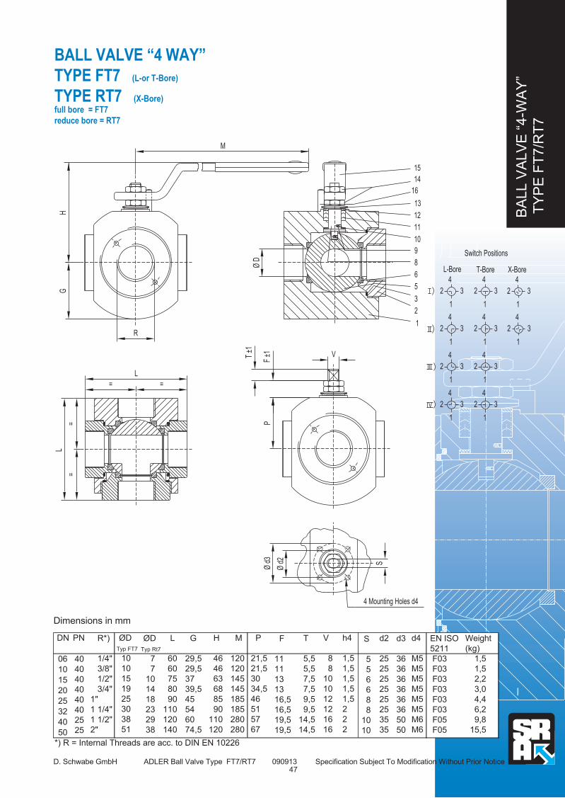
BA
LL V
ALV
E “
4-W
AY
”
TY
PE
FT
7/R
T7
BALL VALVE “4 WAY”
TYPE FT7 (L-or T-Bore)
TYPE RT7 (X-Bore)
full bore = FT7
reduce bore = RT7
D. Schwabe GmbH ADLER Ball Valve Type FT7/RT7 090913 Specification Subject To Modification Without Prior Notice
Dimensions in mm
DN PN R*)
1/4"
3/8"
1/2"
3/4"
1"
1 1/4"
1 1/2"
2"
ØD
Typ FT7
10
10
15
19
25
30
38
51
L
60
60
75
80
90
110
120
140
H
46
46
63
68
85
90
110
120
M
120
120
145
145
185
185
280
280
G
29,5
29,5
37
39,5
45
54
60
74,5
P
21,5
21,5
30
34,5
46
51
57
67
F
11
11
13
13
16,5
16,5
19,5
19,5
T
5,5
5,5
7,5
7,5
9,5
9,5
14,5
14,5
V
8
8
10
10
12
12
16
16
h4
1,5
1,5
1,5
1,5
1,5
2
2
2
06 .. ..
10
15
20
25
32
40
50
*) R = Internal Threads are acc. to DIN EN 10226
40
40
40
40
40
40
25
25
S
5
5
6
6
8
8
10
10
d2
25
25
25
25
25
25
35
35
d3
36
36
36
36
36
36
50
50
d4
M5
M5
M5
M5
M5
M5
M6
M6
EN ISO
5211
F03
F03
F03
F03
F03
F03
F05
F05
Weight
(kg)
1,5
1,5
2,2
3,0
4,4
6,2
9,8
15,5
==
L
=
L
=
T ±1
F ±1
P
V
S
Ø d
2
Ø d
3
4 Mounting Holes d4
Ø D
15
14
13
12
16
10
9
8
5
6
11
3
2
1
Switch Positions
X-Bore4
32
1
3
4
1
2
L-Bore
3
4
2
3
3
1
2
4
1
2
4
3
1
2
4
1
T-Bore
32
4
3
3
3
1
2
1
2
1
2
1
4
4
4
M
HG
R
ØD
Typ Rt7
7
7
10
14
18
23
29
38
47

GE
AR
BO
X
TY
PE
AG
-101 -
AG
-160
GEARBOX
TYPE AG-101 bis AG-160 with Mounting Bracket
for ADLER-BAll Valves
Dimensions in mm
Typ
AG-101
AG-110
AG-120
AG-130
AG-140
AG-160
A
50,5
50,5
79,5
99,0
129,5
148,5
B
117
131
250
274
365
411
C
106
146
205
274
396
455
D
60
60
80
80
100
100
E
56
56
73
97
106
100
F
34
34
35
48
55
48
G
57
57
100
120
150
186
H
98
98
143
188
237
260
ØH
95
95
127
178
215
223
L
46
46
55
74
96
105
ØW
.. ..
M
M6x10/M8x12
M6x10/M8x12
M10x15
M16x20
M20x26
M20x26
EN ISO
5211
F05/07
F05/07
F10
F14
F16
F16
Nm
100
150
500
1000
2000
3250
48D. Schwabe GmbH ADLER Gearbox Type AG 090913 Specification Subject To Modification Without Prior Notice
DE
F
W
A
H
ØH
B
ØW
G
M
EN ISO 5211
120
200
300
400
600
700
Q
22x22
22x22
22x22
27x27
36x36
36x36
q
L
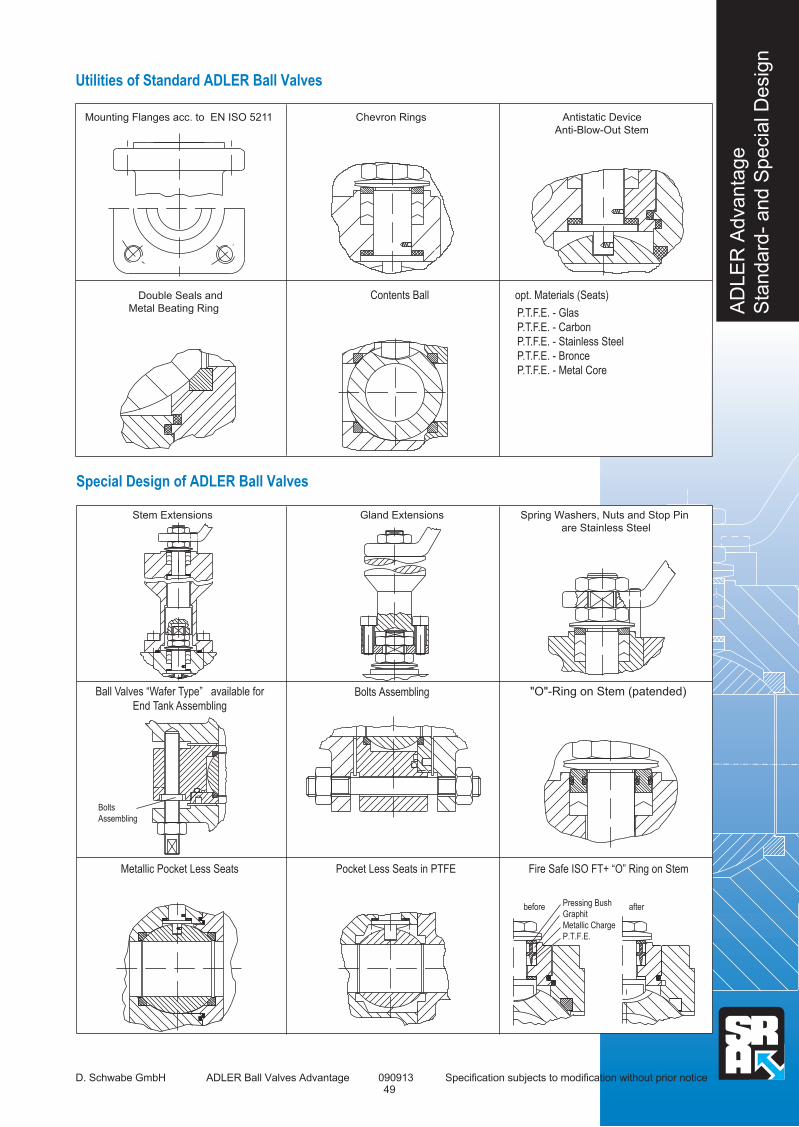
AD
LE
R A
dvanta
ge
Sta
ndard
- and S
pecia
l D
esig
n
Utilities of Standard ADLER Ball Valves
D. Schwabe GmbH ADLER Ball Valves Advantage 090913 Specification subjects to modification without prior notice
Mounting Flanges acc. to EN ISO 5211 Chevron Rings Antistatic Device
Anti-Blow-Out Stem
P.T.F.E. - Glas
P.T.F.E. - Carbon
P.T.F.E. - Stainless Steel
P.T.F.E. - Bronce
P.T.F.E. - Metal Core
Special Design of ADLER Ball Valves
49
Stem Extensions Gland Extensions
Bolts
Assembling
before after Pressing Bush
Graphit
Metallic Charge
P.T.F.E.
Double Seals and
Metal Beating Ring
Contents Ball opt. Materials (Seats)
Ball Valves “Wafer Type” available for
End Tank Assembling
Spring Washers, Nuts and Stop Pin
are Stainless Steel
Bolts Assembling "O"-Ring on Stem (patended)
Metallic Pocket Less Seats Pocket Less Seats in PTFE Fire Safe ISO FT+ “O” Ring on Stem
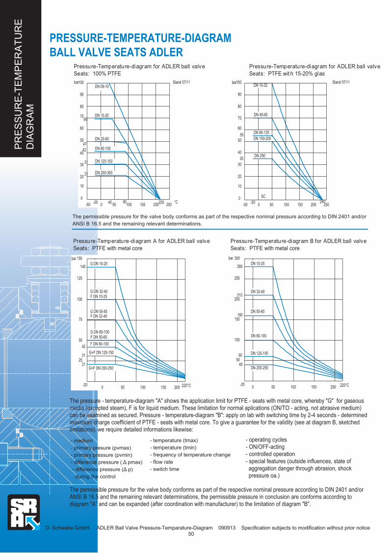
PR
ES
SU
RE
-TE
MP
ER
AT
UR
E
DIA
GR
AM
D. Schwabe GmbH ADLER Ball Valve Pressure-Temparature-Diagram 090913 Specification subjects to modification without prior notice
PRESSURE-TEMPERATURE-DIAGRAM
BALL VALVE SEATS ADLER
Pressure-Temperature-diagram for ADLER ball valve
Seats: 100% PTFE
Stand 07/11
°C250
DN 06-10100 bar
90
80
DN 15-20
DN 25-65
69 70
60
47 50
2001501005090
40
31 30
21
10
20
400
-200
-50
DN 125-150
DN 200-300
42 DN 80-100
220
DN 10-32
DN 40-65
DN 80-125
DN 150-200
ßC
250200150240
DN 250
1000-20
50
100 bar
90
80
70
60
55
50
40
30
35
20
10
0
-50
Stand 07/11
220°C20015010050
300
280
250
bar
210 200
150 160
100
6050
0-20
40
DN 80-100
DN 200-250
DN 125-150
DN 50-65
DN 32-40
DN 10-25
220°C200
G DN 10-25 150 bar
140
125
G DN 32-40F DN 10-25
G DN 50-65F DN 32-40
100
75
15010050
G DN 80-100F DN 50-65
F DN 80-10050
42
2531
0-20
21
G+F DN 125-150
G+F DN 200-250
50
Pressure-Temperature-diagram for ADLER ball valve
Seats: PTFE wit h 15-20% glas
The permissible pressure for the valve body conforms as part of the respective nominal pressure according to DIN 2401 and/or
ANSI B 16.5 and the remaining relevant determinations.
Pressure-Temperature-diagram A for ADLER ball valve
Seats: PTFE with metal core
Pressure-Temperature-diagram B for ADLER ball valve
Seats: PTFE with metal core
The pressure - temperature-diagram "A" shows the application limit for PTFE - seats with metal core, whereby "G" for gaseous media (excepted steam), F is for liquid medium. These limitation for normal aplications (ON/TO - acting, not abrasive medium) can be examined as secured. Pressure - temperature-diagram "B": apply on lab with switching time by 2-4 seconds - determined maximum charge coefficient of PTFE - seats with metal core. To give a guarantee for the validity (see at diagram B, sketched limitations), we require detailed informations likewise:
- medium
- primary presure (pvmax)
- primary pressure (pvmin)
- difference pressure ( 〉 pmax) - difference pressure (〉 p) during the control
- temperature (tmax)
- temperature (tmin)
- frequency of temperature change
- flow rate
- switch time
- operating cycles- ON/OFF-acting- controlled operation- special features (outside influences, state of aggregation danger through abrasion, shock pressure oa.)
The permissible pressure for the valve body conforms as part of the respective nominal pressure according to DIN 2401 and/or ANSI B 16.5 and the remaining relevant determinations, the permissible pressure in conclusion are conforms according to diagram "A" and can be expanded (after coordination with manufacturer) to the limitation of diagram "B".
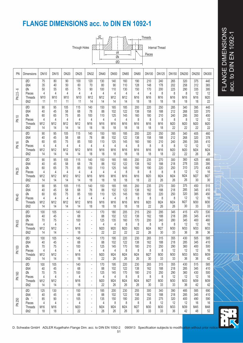
FLA
NG
E D
IME
NS
ION
S
acc. to
DIN
EN
1092-1
FLANGE DIMENSIONS acc. to DIN EN 1092-1
.. ..
D. Schwabe GmbH ADLER Kugelhahn Flange Dim. acc. to DIN EN 1092-2 090913 Specification subjects to modification without prior notice
Threadsd2
Øk
ØD
d4
DN300DN150 DN200 DN250DN100DN80DN50 DN40 DN65 DN125DN25DN15 DN20DN10 DimensionsPN
PN 2
.5 -
6PN
10
PN 1
6
DN32
PN 2
5PN
40
PN 6
3PN
100
PN 1
60PN
250
Pieces
Internal Thread
365395
M2022
12
440312335
258290
M1618
M1618
8 12
202225
18M16
8
265 320 375
370400
12M20
22
378410
12M24
26
485
460
320
12350
268295
8M20
22M20
22
8
212240
22M20
320
12355
268
12295
M24
425
26M20
360
22
8
212240
22M20
285 340 405
285 340 395 445
148170
M1618
4
128150
18M16
4 4
190 21090
110
M1214
4
80100
7090
M121414
4 4
130 140 160110130
M1214
158
8180
M1618
138160
84
18M16
158
8180
M1618
138
8160
4
18M16
200 220
102
4125
M1618
88
4110
78
4M16
1818
102
4125
M1618
88
4110
78
4M16
1818
150 165
122145
M1618
M1618
122145
185
150 165 185 200 220
240178200
8M16
18
250188210
8M16
18
M1618
188
8210
250
Through Holes
6075
M1011
4
5065
4055
M1011
M1011
4 4
80 90 1003550
M1011
4
Ød4Øk
Ød2
PiecesThreads
ØD 75
6885
4M12
14
58
475
4565
4M12
14M12
14
6885
4M12
14
58
475
45
465
M1214
M1214
95 105 115
4
4060
M1214
Ød4Øk
Ød2ThreadsPieces
4
4060
M1214
Ød4Øk
ØD
Ød2ThreadsPieces
ØD 90
ØD 90 95 105 115
120
M12
140
100
M16
M16
100
140
395430
16M27
30
515410
16450
33M30
530
335
12370
278
12310
M27
450
30M24
375
26
8250218
26M24
300345
12385
285
12320
33M30
470
30
415
M278
250218
26M24
345410460
16
36
585
M33
410500
16
42
585
M39
345
12400
285
12345
36
505
36
430
M33 M338
218280
33
355
M30
345400
12
285360
12
36
515
36
430
M33 M3312
218290
33
355
M30
162
8190
M20
235
22
138
8160
8
18M16
200162
8190
22M20
250
138
8160
8
18
215
M16
102
4125
M16
165
18
88
4110
78
4M16
150
1818
102
4125
18M16
180
88
4110
78
4
18M16
170
18
-
18
122
M16
145
18
122
M16
145
185
205162
8200
26
265
M24
138
8170
8
22
230
M20
162210
8
30
265
M27
138180
88
26
230
M24
102
4135
22
195
M20
88
4125-
-
-
22
170
--
-
M20
102145
4
26
195
M24
12588
4
---
22
170
--
-
M20
122160
M2022
220122170
M2426
220
26
188220
M248
26
188
M24
2208
270
295188240
8M27
30
315188250
8M30
33
315
16500
690
42M39
16590
52M48
410
43012
36012
42
585
36
485
M33 M3912
290
33
390
M30
49016
40012
4842M39 M45
12320
36M33
218 285 345
2108
30
300
M27
18088
26
255
M24
2358
33M30
88200
30M27
138 162
1454
26
200
M24
1254
----
22
185
-
-
M20
1508
26M24
1354
--
--
26-M24
10288
M2426
180122230
M2426
170
M3033
275188
12
340
M3033
2508
12288 102 188162138 218 410345285
68
485
14M12
115
58
475
45
465
M12
105
14M12
95
14
68
485
14M12
140
58
475
45
465
14M12
-
14M12
105
4
4060
14M12
90
Ød4Øk
ØD
Ød2
PiecesThreads
4
4060
14M12
100
Ød4Øk
Ød2
ØD
ThreadsPieces
68100
4
18
140
M16
---
45
475
--
-
14
105
M12
1004
68
18
140
M16
---
7545
4--
-
14
105
M12
4
4070
14
100
M12
Ød4Øk
Ød2
ØD
PiecesThreads
47040
14
100
M12
ØkØd4
Ød2
ØD
ThreadsPieces
4100
150
18M16
----
754
-
-
14
130
M12
4105
22M20
--
--
904
-18M16
45 68
470
14
125
M12
Øk
Ød2
ØD
ThreadsPieces
485
18M16
Øk
Ød2ThreadsPieces
Ød4 40
Ød4 40 45 68
100
M16
M16
100
140
14090 95 105 115 300165150 185 200 235 270
51

Notice
Notice
D. Schwabe GmbH ADLER Ball Notice 240912 Specification subjects to modification without prior notice 3

Postfach 1141
D-64854 Eppertshausen
DIETRICH SCHWABE GESELLSCHAFT FÜR STEUER-REGEL-ARMATURENTECHNIK M.B.H.
phone: +49(0)6071-92229- 0
fax: +49(0)6071-92229-11
mail: [email protected]
web: www.schwabe-sra.de
Issue 0913