Asteroid Initiative Opportunities Forum Update on Asteroid - NASA

Icarus 183 (2006) 296–311www.elsevier.com/locate/icarus
Karin cluster formation by asteroid impact
David Nesvorný a,∗, Brian L. Enke a, William F. Bottke a, Daniel D. Durda a, Erik Asphaug b,Derek C. Richardson c
a Department of Space Studies, Southwest Research Institute, 1050 Walnut St., Suite 400, Boulder, CO 80302, USAb Earth Sciences Department, University of California, 1156 High St., Santa Cruz, CA 95064, USA
c Department of Astronomy, University of Maryland, College Park, MD 20742-2421, USA
Received 19 August 2005; revised 14 March 2006
Available online 2 May 2006
Abstract
Insights into collisional physics may be obtained by studying the asteroid belt, where large-scale collisions produced groups of asteroid frag-ments with similar orbits and spectra known as the asteroid families. Here we describe our initial study of the Karin cluster, a small asteroid familythat formed 5.8 ± 0.2 Myr ago in the outer main belt. The Karin cluster is an ideal ‘natural laboratory’ for testing the codes used to simulate large-scale collisions because the observed fragments produced by the 5.8-Ma collision suffered apparently only limited dynamical and collisionalerosion. To date, we have performed more than 100 hydrocode simulations of impacts with non-rotating monolithic parent bodies. We found goodfits to the size–frequency distribution of the observed fragments in the Karin cluster and to the ejection speeds inferred from their orbits. These re-sults suggest that the Karin cluster was formed by a disruption of an ≈33-km-diameter asteroid, which represents a much larger parent body massthan previously estimated. The mass ratio between the parent body and the largest surviving fragment, (832) Karin, is ≈0.15–0.2, corresponding toa highly catastrophic event. Most of the parent body material was ejected as fragments ranging in size from yet-to-be-discovered sub-km membersof the Karin cluster to dust grains. The impactor was ≈5.8 km across. We found that the ejections speeds of smaller fragments produced by thecollision were larger than those of the larger fragments. The mean ejection speeds of >3-km-diameter fragments were ≈10 m s−1. The model andobserved ejection velocity fields have different morphologies perhaps pointing to a problem with our modeling and/or assumptions. We estimatethat ∼5% of the large asteroid fragments created by the collision should have satellites detectable by direct imaging (separations larger than 0.1arcsec). We also predict a large number of ejecta binary systems with tight orbits. These binaries, located in the outer main belt, could potentiallybe detected by lightcurve observations. Hydrocode modeling provides important constraints on the interior structure of asteroids. Our currentwork suggests that the parent asteroid of the Karin cluster may have been an unfractured (or perhaps only lightly fractured) monolithic object.Simulations of impacts into fractured/rubble pile targets were so far unable to produce the observed large gap between the first and second largestfragment in the Karin cluster, and the steep slope at small sizes (≈6.3 differential index). On the other hand, the parent asteroid of the Karincluster was produced by an earlier disruptive collision that created the much larger, Koronis family some 2–3 Gyr ago. Standard interpretationof hydrocode modeling then suggests that the parent asteroid of the Karin cluster should have been formed as a rubble pile from Koronis familydebris. We discuss several solutions to this apparent paradox.© 2006 Elsevier Inc. All rights reserved.
Keywords: Asteroids; Collisional physics
1. Introduction
Our understanding of the Solar System’s past and presentevolution relies, in large part, on numerical codes that are ableto simulate outcomes of large-scale collisions (e.g., Benz and
* Corresponding author. Fax: +1 303 546 9687.E-mail address: [email protected] (D. Nesvorný).
0019-1035/$ – see front matter © 2006 Elsevier Inc. All rights reserved.doi:10.1016/j.icarus.2006.03.008
Asphaug, 1994). These numerical codes are used in a varietyof problems including planetary accretion (e.g., Agnor and As-phaug, 2004; Leinhardt and Richardson, 2004), formation ofplanetary and asteroid satellites (Canup and Asphaug, 2001;Canup, 2004; Durda et al., 2004), collisional evolution of as-teroids (Durda et al., 1998; Bottke et al., 2005), formation ofasteroid families (Michel et al., 2001, 2002, 2003, 2004), andimpact cratering (e.g., Asphaug et al., 1996). The numerical

Karin cluster formation via impact 297
codes, however, are limited in important ways, particularly bythe difficulty to define appropriate failure modes for variousmaterials (see Holsapple et al., 2002).
Insight into the collisional physics may be obtained bystudying the asteroid belt where numerous collisions have in-fluenced the distributions of sizes and spins of asteroids, andhave led to heavily cratered surfaces as evidenced by spacecraftimaging. Asteroid families are probably the most useful struc-tures in the asteroid belt for studying large-scale impacts. Anasteroid family is a group of asteroids with similar orbits andspectra that was produced by a collisional breakup of a largeparent body (Hirayama, 1918). About fifty families have beenidentified in the asteroid belt to date (Zappalà et al., 1994, 2002;Nesvorný et al., 2005). Most of these families are ancient whichmakes it difficult to separate the effects of secondary collisionsand dynamical evolution of family members via thermal effectsfrom the state produced by the original impact (e.g., Marzari etal., 1995; Bottke et al., 2001).
We have recently identified several asteroid families withformation ages <10 Myr (Nesvorný et al., 2002, 2003). Thesefamilies represent nearly pristine examples of ejected frag-ments produced by disruptive asteroid collisions, because theobserved remnants of recent breakups have apparently sufferedlimited dynamical and collisional erosion (Nesvorný and Bot-tke, 2004; Bottke et al., 2005). Studies of the families may helpus to obtain important insights into the physics of large-scalecollisions and may also validate the numerical codes used inother applications listed above.
Recently formed asteroid families may also help us to getimportant insights into our understanding of asteroid interi-ors. Disruptions of monolithic, fractured and ‘rubble-pile’ ob-jects produce characteristic and distinct size–frequency dis-tributions (SFDs) of debris (e.g., Michel et al., 2003, 2004).Therefore, clues to the interior structure of asteroids may beobtained by a careful comparison of the results of impact exper-iments/simulations with the SFDs of observed large fragments.
Here we report the results of our initial study of the as-teroid breakup that led to the formation of the Karin cluster,a ∼5.8 Myr old main-belt asteroid family located at ∼2.866 AU(Nesvorný et al., 2002; Fig. 1). Our analysis is in many wayssimilar to that used by Michel et al. (2003, 2004).
Michel et al. (2003, 2004) were breakthrough works on thissubject. These authors originally proposed that the parent bodyof the Karin cluster was a fractured/rubble pile asteroid. Webelieve this conclusion is not supported by the most recent ob-servational data (Nesvorný and Bottke, 2004). We know nowthat the second largest fragment used by Michel et al., (4507)1990 FV, is in fact a background asteroid with no relation what-soever to the recent breakup (Nesvorný and Bottke, 2004). Oncethis body is removed, a large gap opens between the size of thelargest fragment in the Karin cluster, ≈17-km-diameter (832)Karin, and smaller fragments that have an extremely steep SFDslope (≈6.3 differential power index). Simulation results re-ported by Michel et al. (2003, 2004) for fractured/rubble piletargets do not produce these characteristics.
Interestingly, Michel et al.’s simulations with (unfractured)monolithic parent bodies produced SFDs of fragments which
Fig. 1. Proper orbital elements of ninety Karin cluster members: (a) aP, eP, and(b) aP, iP. The size of each blue symbol is proportional to the diameter of a clus-ter member. Golden dots indicate the background bodies in the Koronis family.The black ellipses show the proper orbital elements of test bodies launchedwith 15 m s−1 speed from aP = 2.8661 AU, eP = 0.04449 and iP = 0.03692,assuming f = 30◦ , and ω + f = 45◦ , where f and ω are the true anomalyand perihelion argument of the parent body. Figure from Nesvorný and Bottke(2004).
show a large gap between the sizes of the largest and smallerfragments. These SFDs are more similar to the revised SFD ofthe Karin cluster and may indicate that the disrupted asteroidwas in fact a monolith. Unfortunately, Michel et al. reportedonly five simulations for monolithic parent bodies (all with a24.5-km diameter; Nesvorný et al., 2002). This small numberof tests makes it difficult to draw firm conclusions about thesize and interior structure of the disrupted asteroid from Michelet al.’s results alone. For this reason, we conducted a detailedstudy of the impact parameter space. Here we report results formonolithic parent bodies.
To date, we performed more than 100 simulations of impactsinto unfractured, monolithic targets. Some of these simulationsproduced strikingly good matches to the observed SFD of theKarin cluster and to the magnitude of the ejection speeds thathas been inferred from the observed orbits. Based on theseresults, we propose that the Karin cluster may have been pro-duced by a disruption of a monolithic (or perhaps only lightlyfractured) parent asteroid. We also determined that this as-teroid had ∼33-km diameter and represented a much largerparent-body mass than suggested by previous estimates [e.g.,

298 D. Nesvorný et al. / Icarus 183 (2006) 296–311
Nesvorný et al. (2002) estimated a ∼25-km diameter of theparent body based on the debiased SFD of observed large mem-bers]. Most mass dispersed into space by this collision is appar-ently contained in <1-km-sized fragments.
We describe our method in Section 2, test it in Section 3,present results and their comparison with observations in Sec-tion 4. We discuss the results in Section 5.
2. Method
We divided the impact and post-impact evolution into threestages and used three different tools to follow the evolution ofthe system in each phase (see also Durda et al., 2004):
• Stage 1: We used a Smooth-Particle Hydrodynamic code(SPH3D; Benz and Asphaug, 1995) to model the initialstage of the impact where processes like shock propaga-tion, fracture and fragmentation determine the evolution ofthe system. The effects of gravity, other than the gravita-tional self-compression of the target, were neglected at thisstage.
• Stage 2: We used an efficient N -body code (pkdgrav;Richardson et al., 2000) to track the gravitational re-accumulation of fragments in the phase following Stage 1.The code simulates the self-gravity and low-speed colli-sions between fragments.
• Stage 3: This stage follows the evolution of bodies froma few days after impact to times where most fragmentsleave the effective Hill sphere. The gravitational force oflargest fragments and the solar gravity are the most impor-tant physical processes during this phase. Hence, we usedan efficient, symplectic N -body code (SyMBA; Duncan etal., 1998) to track the evolution of the system.
We describe these methods in more detail below. The methodof coupling of the SPH calculations with a fast hierarchicalN -body code (used here in Stages 1 and 2) was originally de-veloped by Michel et al. (2001, 2002).
2.1. Stage 1
We modeled the initial stages of impacts between two aster-oids with the 3D SPH code SPH3D (Benz and Asphaug, 1995).SPH3D is a Lagrangian code that solves the mass, momentumand energy conservation equations. It models shock propaga-tion in elastic solids, utilizing a plastic yield criterion for intensedeformation together with an explicit fracture and dynamicfragmentation model acting on the principal tensile componentof the stress tensor during brittle deformation. We adopt frac-ture parameters appropriate for terrestrial basalt (Asphaug etal., 2002). The equation of state used is that of Tillotson (1962),which is based upon the linear relationship between shock andparticle speeds (Melosh, 1989). The Tillotson equation of stategives excellent results in comparison to ejecta speeds derivedfrom laboratory impact experiments (Benz and Asphaug, 1994,1995). Comparison simulations using the ANEOS equation ofstate (Michel et al., 2003, 2004) have shown that for collisions
that do not include significant phase transitions, the details ofthe equation of state do not matter much.
The code ignores gravity because the time scale for shockpropagation through the body and fragmentation is muchshorter than the gravitational time scale (Asphaug, 1997). Weincorporate gravitational self-compression of the target duringthe impact phase as an overburden stress that must be exceededbefore fracture can initiate (Asphaug and Melosh, 1993). Thesimulations were run for 100 real world seconds.
To model the target body we typically used 10,000, 100,000or 200,000 SPH particles. The low resolution runs were usedto explore the parameter space at low CPU cost. The high res-olution runs were used to verify results obtained with 100,000SPH particles. Tests of accuracy are described in Section 3. Wefound that 100,000 or more particles provide sufficient accu-racy.
2.2. Stage 2
When the initial stage of fragmentation/damage is complete,the end states of the SPH models are handed off as the initialstate for the N -body simulations, which follow the trajectoriesof fragments that interact with each other by gravity. We used amodified version of the cosmological N -body code pkdgrav(Stadel, 2001), described in Richardson et al. (2000) (also seeLeinhardt et al., 2000; Leinhardt and Richardson, 2002). pkd-grav is a scalable, parallel tree code that is the fastest codeavailable for this type of simulation. An unique feature of thiscode is the ability to rapidly detect and accurately treat low-speed collisions between particles. This allows for realisticmodeling of the formation of rubble pile accumulations amongejected fragments. See Durda et al. (2004), Richardson et al.(2005) and Leinhardt and Richardson (2005a) for examples ofrecent applications of this code.
The tree component of the code provides a convenient meansto reduce the computational cost. The code uses a second-order leapfrog scheme for the integration and computes gravitymoments from tree cells to hexadecapole order. Particles areconsidered to be finite-sized hard spheres and collisions areidentified during each time step using a fast neighbor searchalgorithm. Low-speed collisions between debris fragments aretreated as mergers resulting in a new spherical particle of ap-propriate combined mass and equivalent diameter.
Different approximations for mergers of debris fragmentswere used by Michel et al. (2002). These tests showed that in-elastic bouncing of colliding fragments may lead to somewhatshallower SFD of small fragments than that produced by fullyinelastic collisions. It is difficult, however, to determine whetherinelastic bouncing of fragments used by Michel et al.’s is anaccurate parametrization of low-speed collisions unless thesecollisions are analyzed in detail (e.g., via SPH simulations). Inthis work, we adopt the simplest approximation where all colli-sions lead to perfect sticking of the colliding fragments.
We used a hierarchical 3D tree code (companion; Lein-hardt and Richardson, 2005b) to search for bound pairs in theoutput. These data were used to estimate the number and prop-erties of binary systems produced by an impact.

Karin cluster formation via impact 299
The N -body simulations were run with a 50-s time step tot = 17 days after the impact (i.e., to 30,000 time steps). Thetime step is a small fraction (about 1/50th) of the relevant dy-namical time defined as (Gρ)−1/2, where G is the gravitationalconstant and ρ is the particle density. We found that the reaccu-mulation in the late stages (t � 8 days) was minimal.
To convert the SPH3D output into input parameters forpkdgrav, we adopted several approximations. First, the SPHparticles were converted into the hard-sphere particles utilizedin pkdgrav. We ensured that the mass was conserved andused density ρ = 2.7 g cm−3 to calculate the radius. Second, wemerged all SPH particles that overlap. When the merger takesplace, we use the conservation of mass and volume to producethe new SPH particle that is then converted into the pkdgravparticle. The velocity of the pkdgrav particle is equal to thatof the corresponding SPH particle. We used a cutoff on densityof SPH particles to detect extended SPH distributions repre-senting vapor. These low-density SPH particles were ignored atthe transition to the pkdgrav because of their generally smallmass.
2.3. Stage 3
During the initial phases of debris cloud expansion, mostfragments are still deep in the effective Hill sphere of the largestfragment, making it possible to neglect the gravitational effectsof the Sun. To estimate the time when the gravity of the Sunstarts to be important, we calculated the mean distance, 〈r〉,of the 100 largest fragments from the largest body and deter-mined its evolution with time. We then compared 〈r〉 to the Hillradius, rH = a(μ/3)1/3, where a = 2.866 AU, μ = mlr/mSun,and where mlr is the mass of the largest fragment and mSun isthe mass of the Sun.
We then hand off the state of the system from pkdgravto SyMBA (Duncan et al., 1998; Levison and Duncan, 2000)when 〈r〉 ∼ 0.5rH, which typically happens about 6–10 daysafter the impact. This value of 〈r〉 was chosen for the follow-ing reasons: (i) The effects of solar tides are negligible forr � 0.5rH, making it possible to ignore solar gravity in sim-ulations with pkdgrav; (ii) The effect of reaccumulation isminimal for t > 6–10 days after impact because the cloud ofdebris is already dispersed in a large space volume; (iii) Thesmall fragments produced by the breakup generally have largervej than large fragments (see Section 4.2). For this reason, att ∼ 6–10 days, small fragments are dispersed in a large volumemaking it possible to neglect the effects of their gravity on thetrajectories of the largest surviving fragments. This allows usto speed up the calculation by tracking only the trajectories ofseveral hundreds of gravitationally interacting large fragments.This allowed us to run many Stage-3 simulations with differ-ent impact locations/orientations in the Sun-centered referenceframe.
SyMBA is a symplectic integrator that has the desirableproperties of the sophisticated and highly efficient numerical al-gorithm known as Wisdom–Holman Map (WHM; Wisdom andHolman, 1991) and that, in addition, can handle close encoun-ters (Duncan et al., 1998). This technique is based on a variant
of the standard WHM, but it handles close encounters by em-ploying a multiple time step technique (Biesiadecki and Skeel,1993). When bodies are well separated, the algorithm has thespeed of the WHM method, and whenever two bodies suffer amutual encounter, the time step for the relevant bodies is recur-sively subdivided.
We follow the trajectories of self-gravitating largest frag-ments from within the Hill sphere to distances where their be-havior is controlled by solar gravity. The resulting orbits areconverted back to ejection velocities using Gauss’ equations(see below). We then compare these values with the originalejection velocities. This procedure allows us to determine theeffect of collective interactions in late stages of debris evolutionand the validity of the usual Gauss-equation-based procedure toderive ejection velocities from the observed orbital parametersof an asteroid family.
3. Tests
3.1. Reproducibility
To test the reproducibility of our results, we ran several sim-ulations twice on different processors. We also used differentstep sizes and changed error control parameters. We found thatthe results were almost exactly the same. This means the resultsof our simulations are reproducible when the initial parametersof the impact are the same.
3.2. Dependence on SPH resolution
We tested the dependence of our results on SPH resolutionby: (i) performing several simulations with exactly the sameimpact parameters except for the target’s diameter, which wechanged by ∼1 cm between individual runs, and (ii) varyingthe number of SPH particles between 10,000 and 200,000.
Results from (i) with only 10,000 SPH particles showed sig-nificant variability. The diameters of the 1st and 2nd largestfragments varied by as much as ≈1 km and ≈2 km, respec-tively, between individual runs. This variability was suppressedwhen 100,000 particles were used. With 100,000 particles, d1stand d2nd fluctuated only by ≈0.2 km and ≈0.7 km, respectively,and were similar to values obtained in our experiments with200,000 SPH particles. This is an indication of an improvedconvergence of results when �100,000 particles are used. Wealso found a similar dependence on resolution when comparingthe momentum imparted in the largest escaping fragments.
While encouraging, these tests are inconclusive because thenumber of SPH particles may not have been varied sufficiently.W. Benz (personal communication) has conduced similar testsof convergence of the SPH code in the regime of laboratoryimpacts. By using up to 2,240,000 SPH particles he showedthat the size of the largest fragment may vary when differentnumbers of SPH particles are used. He attributed these resultsto the fact that the average explicit fracture threshold increaseswith the number of particles.
It is not clear whether our code may suffer from the sameproblem. The tests of W. Benz described above do not include

300 D. Nesvorný et al. / Icarus 183 (2006) 296–311
Stage 2 where the size of the largest fragment increases by reac-cumulation of fragments. Moreover, uncertainties in the albedovalues of Karin cluster members (discussed below) appear to bemore important than the effects of the SPH resolution.
4. Results
The non-rotating targets were assumed to be spherical andwere composed of unfractured, monolithic basalt with a densityof 2.7 g cm−3. We used spherical basalt impactors. To set up theSPH simulation, we selected the target and impactor sizes, dtarand dimp, respectively, the impact speed, vimp, and the impactangle, θ . We performed more than 100 simulations with differ-ent dtar, dimp, vimp and θ . These simulations were divided intofive classes:
• Class 1: nominal case with vimp = 5 km s−1 and θ = 45◦.• Class 2: low-speed impact case with vimp = 3 km s−1 and
θ = 45◦.• Class 3: high-speed impact case with vimp = 7 km s−1 and
θ = 45◦.• Class 4: nearly head-on impacts with vimp = 5 km s−1 and
θ = 15◦.• Class 5: oblique impacts with vimp = 5 km s−1 and θ = 75◦.
According to Bottke et al. (1994), vimp = 5 km s−1 isroughly the mean collision speed between main belt aster-oids. Collisions with vimp = 3 km s−1 and vimp = 7 km s−1 areabout 30% and 50% less likely, respectively, than a collisionwith vimp = 5 km s−1. Also, (832) Karin has ≈4.1 km s−1 rmscollision speed with the main belt asteroids (intrinsic collisionprobability Pi ≈ 4 × 10⁻¹⁸ km−2 yr−1). Therefore, values ofvimp used here span the interesting range of impact speeds.
The rate of collisions with θ is proportional to sin θ . Thus,collisions with θ = 75◦ and θ = 15◦ are about 40% moreand 60% less likely, respectively, than a collision with θ = 45◦.This argument cannot be used to favor grazing impacts as themost likely collision geometries for the Karin cluster forma-tion because high-probability near-grazing impacts on a targetbody can produce catastrophic breakups only if the impactor isbig. Because the number of relevant-size asteroid impactors inthe main belt strongly decreases with d , however, catastrophicnear-grazing impacts are relatively rare compared to those withsmaller θ .
We performed simulations in each class with many dif-ferent dtar and dimp. First, we selected dtar and dimp using atrial and error method and comparing our results to the size-distribution of the Karin cluster. In all cases except for Class-2parameters, we were able to find an acceptable fit after 4 to 7test simulations. The outcomes of low-speed Class-2 impactsimulations are sensitive to small changes in dtar and/or dimp,which makes it difficult to converge toward a desired solution.
In the second step, we have run exploratory, low-resolutionsimulations with 10,000 SPH particles to test the behavior ofthe SFD for impact parameters near the solution found above.This effort helped us establish the envelope of values that mayprovide good fits to the observed SFD. For example, the best
solution for Class 1 found above is dtar = 30 km and dimp =5 km. Hence, we used dtar = 26, 28, and 32 km and dimp =4.0,4.5,5.0,5.5 and 6.0 km in step two, 20 simulations in total.
We analyzed these low-resolution results and selected theinitial parameters for high-resolution simulations (100,000 SPHparticles) that were designed to map the interesting part ofthe parameter space. The simulation outcomes with impact pa-rameters that provided the best matches to the observationaldata were selected for further analysis, including additional200,000-SPH-particle simulations, a detailed comparison of theejection velocity fields, search for binaries, and discussion ofthe rotation of the largest fragment. We describe these resultsbelow.
Our best-fit solutions to the observed parameters of the Karincluster are not unique because we explore only five representa-tive planes in the four-dimensional space of parameters (dtar,dimp, vimp, and θ ). Moreover, we limited our initial study ofthis problem to spherical, monolithic, basaltic, and non-rotatingtargets and impactors. Other setups, including different assump-tions on the interior structure of the parent body, rotating tar-gets, low-density C-type impactors, etc., will be described inforthcoming papers.
4.1. Size–frequency distribution
4.1.1. Observed SFDThe size–frequency distribution (SFD) of the Karin cluster
is shown in Fig. 2. We used 90 members selected by Nesvornýand Bottke (2004) from a catalog of ∼220,000 asteroid or-bits. Given the restrictive criterion for membership used by
Fig. 2. The cumulative size–frequency distribution of Karin cluster mem-bers identified in Nesvorný and Bottke (2004). Absolute magnitudes listed inthe Minor Planet Center catalog were converted into diameters using albedopV = 0.2; each individual member’s diameter is labeled by a circle. The best-fitpower index to the slope between 3 and 5.5 km diameters is ∼5.3 (dashed line).This very steep slope changes for diameter <3 km due to the observationalincompleteness. Left and right solid lines show SFDs that we obtained withpV = 0.26 and pV = 0.14, respectively.

Karin cluster formation via impact 301
Nesvorný and Bottke very few of these asteroids should be in-terlopers. Also, given the young age of the family, we assumethat: (i) secondary fragmentation events among the originalfragments did not change the SFD of diameter d > 1 km mem-bers in significant ways (Bottke et al., 2005), and (ii) the orbitsand spins of the fragments were not modified in important waysby the Yarkovsky and YORP effects (Nesvorný and Bottke,2004). Therefore, these asteroid fragments present a clear-cutcase of debris distribution produced by a disruptive collisionbetween asteroids.
To determine the size of an object from the absolute magni-tude, H , we need to know its visual albedo, pV . Unfortunately,albedo values of Karin cluster members are unknown. To es-timate these values, we used the fact that the parent body ofthe Karin cluster was an S-type member of the Koronis family(Jedicke et al., 2004; Nesvorný et al., 2003, 2005). The SIMPScatalog (Tedesco et al., 2002) lists albedo values for 24 Koronisfamily members. Their mean albedo is 0.198 ± 0.012. The rmsvariation is 0.061, illustrating the large spread of albedo val-ues in the Koronis family. To account for this uncertainty, weused pV = 0.14, 0.2 and 0.26 as three possible values of albedofor the Karin cluster members. pV = 0.2 is our nominal case,pV = 0.14 and pV = 0.26 were chosen to span the rms varia-tion in the Koronis family.
Corresponding to H = 11.18, the diameter of (832) Karin is17.1 km for pV = 0.2. It is 15.0 km for pV = 0.26 and 20.5 kmfor pV = 0.14. Similarly, the second largest fragment, (13907)1998 XE13, has H = 13.7 and the mean, minimal and maximaldiameters d2nd = 5.4, 4.7 and 6.4 km, respectively.
Our sample of Karin cluster members is observationally in-complete. This is clearly seen at the transition from d > 3 km,where the observed SFD is characterized by a steep slope, tod < 2 km, where very few Karin cluster members are known(Fig. 2). We did not try to debias the sample because that wouldrequire that we make several non-trivial assumptions about theefficiency of observational surveys. Instead, we used only mem-bers with d > 3 km for which the effects of incompleteness areless severe.
We assumed that the cumulative size distribution, N(> d),can be locally described by a power law, N(> d) ∝ d−α , withthe best-fit α found by the least-squares method. The best fits tothe observed distribution between 3- and 5.4-km diameters (forpV = 0.2) occurs for α = 5.3 ± 0.5.
With pV = 0.2, the total volume of 90 fragments corre-sponds to a sphere with a ≈20 km diameter. Assuming a 20-km-diameter parent body, mlr/mpb ∼ 0.63, suggesting a sub-catastrophic event. In fact, we will show below that mlr/mpb ≈0.15–0.2, corresponding to a highly catastrophic impact, witha large fraction of the parent body hiding in small fragmentsbeyond the observational detection limit.
4.1.2. Model SFDsWith vimp = 3 km s−1 and θ = 45◦ (Class 2 impacts), we
did not find dtar and dimp values that would produce a SFDsimilar to that observed in the Karin cluster (2). This probablymeans that these parameter choices are unlikely to match theconstraints. We also noticed that the momentum imparted into
the large fragments by our Class-2, low-speed impacts is gen-erally much larger than the one inferred from observations ofthe Karin cluster (see Section 4.2.2). Consequently, the ejectionspeeds are too large. Given these results, we find it unlikely thatClass-2, low-speed impacts might produce reasonable analogsfor the Karin cluster. We will not discuss low-speed impactsfurther in this paper.
Fig. 3 shows the result of our fifteen 100,000-SPH-particlesimulations of Class-3 impacts (vimp = 7 km s−1 and θ = 45◦).To cope with uncertainties in pV , we have spread these sim-ulations in parameter space to produce fragments that are assmall as 15.2 km and as large as 20.0 km. The red regions inFig. 3 correspond to values of dtar and dimp that produce goodmatches to the observed SFD. A good match is defined hereas one producing 15.0 � dlr � 20.5 km (panel a), 4.7 � d2nd �6.4 km, where d2nd is the diameter of the second largest frag-ment (panel b), and 4.6 � α � 5.8 (panel c). The mean ejectionspeed (panel d) will be discussed in Section 4.2
Fig. 4 shows an example of a Class-3 simulation where wehave obtained a good match to the observed SFD (Table 1).The initial parameters of this simulation were dtar = 33 kmand dimp = 5.75 km (denoted by star in Fig. 3). The largestsurviving fragment has d = 17.0 km (to be compared to ob-served d = 17.1 km for pV = 0.2), the second largest frag-ment has d = 4.8 km (compare to observed d = 5.4 for pV =0.2), the power index, α, of the cumulative sized distribution,N(> d) ∝ d−α , is ≈5.3 (compare to observed α = 5.3 ± 0.5).
The best fits to the size of the largest fragment occur alonga diagonal area in dtar and dimp space (Fig. 3a). Apparently,a larger impactor is needed for a larger target body to pro-duce observed dlr ≈ 17 km. The linear dependence betweendtar and dimp may be empirically described by d∗
imp = 4.6 km +0.33(dtar − 30 km). Impactors that are significantly larger thand∗
imp for fixed dtar produce dlr that are too small, and viceversa.
It is possible to match dlr over a large range of dtar but a morelimited range of dtar produces good matches to both dlr andd2nd. Fig. 3b illustrates this result. To match d2nd, dimp needs tobe between ≈4.5 and ≈6 km (for a basaltic, ρ = 2.7 g cm−3,Class-3 impactor). If the impactor’s diameter is larger than≈6 km, model d2nd becomes significantly larger than the ob-served d2nd ≈ 5.4 km. If dimp < 4.5 km, model d2nd becomessignificantly smaller than observed d2nd. The range of plausibledtar corresponding to 4.5 � dimp � 6 km is 29 � dtar � 35 km.
A tighter range of dtar values is required to match the ob-served SFD’s slope (Fig. 3c). In general, the model slopes areshallower than those observed. The model SFD’s slope indexexceeds α ≈ 4.8 for only a special combination of dtar anddimp. Most steep slopes occur for 31 � dtar � 34 km, withdtar ≈ 33 km and dimp ≈ 5.8 km producing best fits to observedα ≈ 5.3.
These results are encouraging. We were able to identify onepossible set of impact parameters that produces a satisfactorymatch to the observed SFD (see Fig. 4). These parameters are:dtar ≈ 33 km, dimp ≈ 5.8 km, vimp ≈ 7 km s−1 and θ ≈ 45◦.Moreover, we will show below that the magnitude of the ejec-tion speeds inferred from observations can be also fit by using

302 D. Nesvorný et al. / Icarus 183 (2006) 296–311
Fig. 3. Location of good model fits to the Karin cluster as a function of target and impactor diameters for vimp = 7 km s−1 and θ = 45◦ (our Class-3 impactsimulations). A good fit (denoted in red) is defined here as the one producing 15.0 � dlr � 20.5 km (a), 4.7 � d2nd � 6.4 km (b), 4.6 � α � 5.8 (c), and9.8 � 〈vej〉 � 16.8 m s−1 (d), where mean speed 〈vej〉 was calculated as the average over ejection speeds of the 2nd to 90th largest fragments with respect tothe 1st largest fragment. The solid lines in (a) and (b) denote Class-3 simulations with dtar and dimp that produce dlr = 17.1 km and d2nd = 5.4 km, which are theestimated sizes of the largest and second largest members of the Karin cluster for pV = 0.2. The place where these two lines cross (near the location of star) iswhere the best fits were obtained for pV = 0.2. The SFD for dtar and dimp denoted by the star is shown in Fig. 4. Shaded regions were not sampled.
the model parameters described above. Taken together, our re-sults indicate that the parent body of the Karin cluster couldhave been a d ≈ 33-km monolithic asteroid that collided witha high-speed, d ≈ 5.8-km impactor. We will discuss this resultand its implications in more detail in Section 5.
The best results of our Class-1 simulations (vimp = 5 km s−1
and θ = 45◦) occur for dtar ≈ 30 km and dimp ≈ 5 km. Thesesimulations typically produce dlr and d2nd that are in the sameballpark as the observed values. Interestingly, these simulationsproduce shallow SFD slopes with α � 4 that are incompatiblewith α = 5.3 ± 0.5 inferred from observations. This may be ex-plained by one or more of the following reasons: (i) We maynot have sampled parameter space sufficiently with our twenty10,000 and ten 100,000 SPH particle simulations in Class 3;other (non-sampled) combinations of dtar and dimp could pro-duce steeper slopes. (ii) vimp ≈ 5 km s−1 impacts generallyproduce shallower slopes than impacts with higher vimp. If (ii)applies, a high-speed collision may better explain the SFD ofthe Karin cluster than vimp = 5 km s−1. Further work will beneeded to resolve this issue.
The best result for Class-1 impacts was obtained with dtar =32 km and dimp = 5 km. This simulation produced dlr =
18.5 km, d2nd = 6.2 km and α = 4.2 (Table 1). Except for aslightly shallower slope, the fit to the observed SFD is good(Fig. 5).
Fig. 6 illustrates the difficulty in fitting the observed distrib-ution with Class-4 impacts (θ = 15◦; nearly head-on impacts).We were able to find impact parameter values that produce cor-rect sizes for the 1st and 2nd largest fragments in the Karin clus-ter but incorrect distribution at small d . In Fig. 6, the model SFDdoes not sharply increase from d2nd ∼ 5.4 km as the observedSFD but instead continues with a shallow slope to d ∼ 2.8 km,where it has an inflection point. This behavior is typical for allnearly head-on impacts that produce desired values of dlr andd2nd. For this reason, we believe that the Karin cluster was morelikely produced by an impact with larger θ .
The best result for Class-4 impacts was obtained with dtar =28 km and dimp = 4 km. This simulation produced dlr =16.6 km, d2nd = 4.8 km and α = 4.7 (Table 1). The model SFD,however, suffers from the same problem as the one shown inFig. 6, where model fragments are smaller than the observedones for d < 5 km.
Our Class-5 simulations (θ = 75◦; oblique impacts) requirelarger impactors than more centered impacts to produce the ob-

Karin cluster formation via impact 303
Fig. 4. Example of a good model fit to the observed size–frequency distribu-tion that we obtained for dtar = 33 km, dimp = 5.75 km, vimp = 7 km s−1 andθ = 45◦ . The observed (for pV = 0.24) and model SFDs are denoted by circlesand a line, respectively. For smaller pV , the observed SFD would shift slightlyto the right (see Fig. 2) and would require a slightly larger dtar and dimp.
Table 1Impact parameters and results for three selected simulations
(obs.) (1) (2) (3)
dtar (km) 32 33 28dimp (km) 5.5 5.75 4.0vimp (km s−1) 5 7 5θ (◦) 45 45 15dlr (km) 17.1 18.5 17.1 16.6d2nd (km) 5.4 6.2 4.8 4.8α 5.3 4.2 5.3 4.7mlr/mpb 0.19 0.14 0.21vlr (m s−1) 10.5 6.9 5.0〈vej〉 (m s−1) 12.7 10.1 11.2 10.0
Notes. The rows are: diameter of the target body (dtar); diameter of the im-pactor (dimp); impact speed (vimp); impact angle (θ ); diameter of the largestfragment (dlr); diameter of the second largest fragment (d2nd); cumulative SFDslope index (α); largest remnant to parent body mass ratio (mlr/mpb); post-impact speed of the largest remnant (vlr); and the mean ejection speed of the2nd to 90th largest fragments with respect to the largest fragment (〈vej〉). Thecolumns show: (obs.) values obtained from observations; (1) Class 1 simu-lation with dtar = 32 km and dimp = 5.5 km; (2) Class 3 simulation withdtar = 33 km and dimp = 5.75 km; (3) Class 4 simulation with dtar = 28 kmand dimp = 4.0 km. Observed quantities were derived from orbits and sizes ofninety Karin cluster members with f = 30◦ , ω+f = 50.5◦ and pV = 0.2. Ourpreferred model parameters and results are denoted in bold.
served dtar and dimp values. For example, dtar = 27.5 km anddimp = 9 km produce SFDs that have roughly the correct val-ues of dlr and d2nd, and a steep, slightly concave distributionat small d . We have two reasons, however, to believe that anoblique impact is a less likely scenario for the origin of theKarin cluster. First, the likelihood of an impact of an ≈9-km-diameter asteroid is ∼5–10 times less likely than an impact ofan ≈5-km-diameter asteroid because smaller asteroids are moreabundant in the main belt than the larger ones (Bottke et al.,
Fig. 5. Example of a model fit to the observed size–frequency distribution thatwe obtained for dtar = 32 km, dimp = 5.5 km, vimp = 5 km s−1 and θ = 45◦ .The observed (for pV = 0.2) and model SFDs are denoted by circles and a line,respectively. The model SFD is slightly shallower than the observed one for3 < d < 6 km.
Fig. 6. Example of a model SFD that we obtained for dtar = 30 km,dimp = 4.5 km, vimp = 5 km s−1 and θ = 15◦ . The observed (for pV = 0.2)and modeled SFDs are denoted by circles and a line, respectively. The modeldistribution fits very well the sizes of 1st and 2nd largest fragments but fails toproduce the observed SFD at small d .
2005). Second, the ejection speeds of fragments produced byoblique impacts are substantially larger than the observed ones(see next section). This happens because only a small part ofthe target and impactor bodies overlap along the impact path.Therefore, there is less opportunity to convert the kinetic en-ergy of the impactor into other energy forms. Also, for obliqueimpacts, the impactor material typically contributes to the massof the second largest fragment.
304 D. Nesvorný et al. / Icarus 183 (2006) 296–311
4.2. Ejection velocity
4.2.1. vej deduced from observationsThe ejection velocity of fragments may be determined from
the observed distribution of proper orbital elements of Karincluster members. We assume that the proper elements have notsignificantly changed over the family’s age. Indeed, given theyoung age of the Karin cluster, the effects thermal forces andgravitational encounters with large asteroids are negligible inthe current context (Nesvorný and Bottke, 2004).
We used Gauss equations (e.g., Murray and Dermott, 1999,p. 54) to relate the orbital elements of a Karin cluster member(aP, eP and iP) to the components of its ejection velocity, vej,along the direction of the orbital motion, vt , in the radial direc-tion, vr , and perpendicular to the orbital plane, vw:
δa/a = 2
na(1 − e2)1/2
[(1 + e cosf )δvt + (e sinf )δvr
],
δe = (1 − e2)1/2
na
[e + 2 cosf + e cos2 f
1 + e cosfδvt + (sinf )δvr
],
(1)δi = (1 − e2)1/2
na
cos(ω + f )
1 + e cosfδvw.
Here, δa = aP − aref, δe = eP − eref and δi = iP − iref, wherearef, eref and iref define a reference orbit, and f and ω are thetrue anomaly and the perihelion argument of the disrupted par-ent body at the instant of the impact.
A natural reference frame for our impact simulations is theone fixed at the target body. Unfortunately, it is difficult to usethis frame for the observed fragments without a priori knowl-edge of the impact parameters. We therefore use a differentframe which can be easily defined for both the SPH-derivedand observed velocities. In our SPH simulations, we fix thereference frame at the largest surviving fragment and calcu-late the velocities of smaller fragments with respect to thelargest fragment. To determine ejections velocities from the ob-served orbits, we use aref = 2.8644 AU, eref = 0.043921 andiref = 2.11203◦, corresponding to (832) Karin, and calculate vt ,vr and vw from inverted Eq. (1).
The transformation from a, e, i to vt , vr , vw depends on thetrue anomaly, f , and the argument of perihelion, ω, of the refer-ence orbit. The exact values of these parameters are unknown.From the tilt of the distribution in a, e (Fig. 1), it has been sug-gested that |f | � 30◦ (Nesvorný et al., 2002). We experimentedwith f = 10◦ and f = 30◦. Values of f < 10◦ produce ejectionvelocity fields with unrealistically large vt .
The value of ω is not constrained unless we make explicitassumptions about the ejection velocity field. For example,isotropic ejection velocity fields produce the observed distri-bution of orbits if |ω + f | � 45◦ or |ω + f + 180◦| � 45◦(Nesvorný et al., 2002). In Eq. (1), δi ∝ vw cos(ω + f ). Weused ω+f = arccos〈cos(ω+f )〉 = 50.5◦, where 〈cos(ω+f )〉is the average over randomly distributed ω. The inferred val-ues of vw would be about 1.5 times smaller if ω + f ∼ 0◦ or180◦ and much larger if ω + f ∼ 90◦ or 270◦. We believe thatω + f ∼ 90◦ or 270◦ did not occur because vw would be muchlarger than vt and vr . None of our Karin impact experiments to
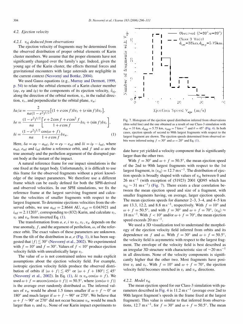
Fig. 7. Histogram of the ejection speed distribution inferred from observations(thin solid line) and the one obtained as a result of our Class-3 simulation withdtar = 33 km, dimp = 5.75 km, vimp = 7 km s−1 and θ = 45◦ (Fig. 4). In bothcases, ejection speeds of second to 90th largest fragments with respect to thelargest fragment are shown. The ejection speeds determined from observed or-bits were inferred using f = 30◦ and ω = 20◦ and Eq. (1).
date have yet yielded a velocity component that is significantlylarger than the other two.
With f = 30◦ and ω + f = 50.5◦, the mean ejection speedof the 2nd to 90th largest fragments with respect to the 1stlargest fragment, is 〈vej〉 = 12.7 m s−1. The distribution of ejec-tion speeds is broadly shaped with values of vej between 0 and26 m s−1 (with exception of (51923) 2001 QD95 which hasvej ∼ 31 m s−1) (Fig. 7). There exists a clear correlation be-tween the mean ejection speed and size of a fragment, withsmaller fragments having, on average, larger ejection speeds.The mean ejections speeds for diameter 2–3, 3–4, and 4–5 kmare 13.3, 12.2, and 8.8 m s−1, respectively. With f = 10◦ andω + f = 50.5◦, and with f = 30◦ and ω + f = 70◦, 〈vej〉 ≈18 m s−1. With f < 10◦ and/or ω +f = 70◦, the mean ejectionspeed exceeds 20 m s−1.
We used a 3D visualization tool to understand the morphol-ogy of the ejection velocity field inferred from orbits and itsdependence on f and ω. With f = 30◦ and ω + f = 50.5◦,the velocity field is asymmetric with respect to the largest frag-ment. The envelope of the velocity field is best described asan irregular 3D structure with characteristic size of ∼20 m s−1
in all directions. None of the velocity components is signifi-cantly higher that the other two. Most fragments have posi-tive vt and vr . With f = 10◦ and ω + f = 70◦, the ejectionvelocity field becomes stretched in vr and vw directions.
4.2.2. Model vej
The mean ejection speed for our Class-3 simulation with pa-rameters described in Fig. 4 is 11.2 m s−1 (average over 2nd to90th largest fragment’s speeds in the frame fixed at the largestfragment). This value is similar to that inferred from observa-tions, 12.7 m s−1, for f = 30◦ and ω + f = 50.5◦. The mean

Karin cluster formation via impact 305
Fig. 8. The ejection velocities of hundred largest fragments produced by our Class-3 simulation with dtar = 33 km, dimp = 5.75 km. Panels show three differentprojections of vej. The size of a symbol is proportional to the fragment’s diameter. In this experiment, the target with vx = 0, vy = 0, vz = 0 was impacted at a 45◦angle by a projectile with vx = −7 km s−1 and vy = 0, vz = 0. Accordingly, the impact produced negative vx and vy of the largest fragment. Characteristic raysthat resemble the rays of larger craters on the Moon can be seen in panels (a) and (c).
ejections speeds for diameter 2–3, 3–4, and 4–5 km are 12.3,10.7, and 7.6 m s−1, respectively, which is also in good agree-ment (slightly lower) with the observed values (13.3, 12.2, and8.8 m s−1 for f = 30◦ and ω + f = 50.5◦; see previous sec-tion). This shows that our Class-3 simulations are able to pre-dict the correct magnitude of the ejection speeds and the size-ejection speed correlation observed in the Karin cluster.
Similarly good agreement between magnitudes of the modeland observed speeds exists for simulations in Classes 1 and 4(Table 1). Conversely, Class-2 and Class-5 impacts (low impactspeed and oblique impacts) produce ejection speeds in excessof 20 m s−1. These ejection speeds cannot be ruled out a prioribecause of the uncertainty produced by unknown f and ω + f .Yet, combined with our difficulties to produce correct SFD withClass-2 and Class-5 parameters, and the large dimp required inClass 5 (see Section 4.1.2), we believe that these impact para-meters (low vimp and/or large θ ) are unlikely.
All simulations conducted here produced ejection velocityfields with characteristic morphology (Fig. 8). For θ = 15◦ andθ = 45◦, the distribution of vej is a flat, warped structure that isnearly perpendicular to the velocity vector of the largest frag-ment. The individual ejection velocity vectors are distributednon-randomly in the disk forming nearly radial rays that re-semble the rays of large craters on the Moon. Oblique impactsproduce velocity field morphologies that are more bowl-shaped.Conversely, the velocity field inferred from Karin members’ or-bits is generally a more isotropic, 3D structure (Section 4.2.1).
We can think of several ways to explain the difference be-tween the morphologies of the model and observed velocityfields. One possibility is that our estimate of f and ω is in-correct. If f ∼ 0◦ and ω + f ∼ 90◦, the ejection velocity fieldinferred from the observations would become more similar tothe simulated one. Moreover, 2002 CX104, 1994 EX, 2000UV4, (40510) 1999 RU87 could form a ray in velocity spacelike the ones produced in our simulations. Another option isthat our modeling may be missing some important componentof debris evolution. For example, the solar gravity may modify
the velocity field of escaping fragments in the later stages of thedebris cloud’s expansion.
To test this possibility, we have performed a series of Phase-3 simulations (see Section 2.3). To set up the initial con-ditions these simulations, we used the distributions of frag-ments at time t ≈ 8 days after impact, when some particlesare still deep within the effective Hill sphere of the largestfragment. For example, for our preferred Class-3 impact para-meters (dtar = 33 km and dimp = 5.75 km), the mean distanceat t = 8 days of the 100 largest fragments from the largest frag-ment is ≈8000 km. This turns out to be about rH/2, whererH ≈ 16,000 km is the Hill radius of a d ≈ 17 km largest frag-ment at 2.865 AU (assuming 2.7 g cm−3 density).
At t ≈ 8 days, we include the Sun’s gravity in the simulationand track the evolution of fragments to times where most largefragments become separated by several of their effective Hillradii. The gravitational attraction between the large fragmentsand solar gravity determines the final orbits. We then use theGauss equations [Eq. (1)] to map the final orbits back to ejectionvelocities and compare them with the original velocity field likethat shown in Fig. 8. The integration method is described inSection 2.3.
We found that in a few instances typical for fragments thathave barely enough speed to escape from the largest fragment,solar perturbations can be important. In general, however, theejection velocity field is well represented by our Phase 2 sim-ulations and is not substantially modified by Sun’s gravity.This result can be explained by comparing the ejection speedsof fragments with the Hill velocity, vH = vK/2(μ/3)1/3 ≈0.3 m s−1, where vK is the Kepler velocity. Because the ejec-tion speeds are typically at least one order in magnitude largerthan vH, we conclude, in agreement with our Phase 3 results,that the solar gravity should not modify the velocity field offragments in important ways (at least for Karin-cluster formingimpacts). We discuss other, more plausible options that may ex-plain the difference between model and observed velocity fieldsin Section 5.

306 D. Nesvorný et al. / Icarus 183 (2006) 296–311
Fig. 9. The orbits of largest fragments produced by an impact experiment de-fined by dtar = 33 km, dimp = 5.75 km, vimp = 7 km s−1, θ = 45◦ , f = 10◦and ω + f = 50.5◦ . The size of a symbol is proportional to the fragment’s di-ameter. The impact was set to occur along r direction. This model result showsa remarkable similarity to the distribution of observed orbits of Karin clustermembers (see Fig. 1).
To set up a Phase 3 simulation, we must choose f , ω and theorientation of the impact in the heliocentric reference frame. Byvarying these parameters, we found that impacts along the ra-dial direction (roughly perpendicular to both the normal to theorbital plane and the orbit velocity vector) can best explain theorbits of the Karin cluster. For this orientation, the referenceframe of the SPH/pkdgrav simulations (x, y, z; impact occur-ring along x and toward negative x; target hit at positive y andz = 0) coincides with a local orbital frame defined by r , t , w,where r , t , w are radial, tangential and orbit-normal vectors atthe instant of impact.
Fig. 9 illustrates a result of one such impact experiment.In this figure, the largest fragment is offset toward smaller a
with respect to the center of the family in the same way (832)Karin is offset from the center of the Karin cluster (Fig. 1).This happens because vy of the largest fragment is negative(see Fig. 8b). Therefore, vt is also negative due to the choiceof the impact orientation in the orbital frame, and δa < 0 fromGauss equations [Eq. (1)]. The largest fragment is more sym-metrically placed in i with respect to other fragments becauseits vz ≈ 0 (see Fig. 8a). Together, these impact conditions createthe desired effect where the appearance of the synthetic family
in a, e, i (Fig. 9) looks very similar to that of the observed Karincluster (Fig. 1).
The impact orientation discussed above is not unique. Im-pacts along vt may also produce a good match to observa-tions. These impacts between main belt asteroids, however, aremuch less likely than those along vr (Bottke et al., 1994). Im-pacts along vw direction produce an asymmetric position of thelargest fragment in proper inclination which is not observed.Thus, we believe impacts along vw can be ruled out.
4.3. Binary formation
Hydrocode simulations show that a large number of initialbinaries can be produced among escaping ejecta by an aster-oid collision (so-called Escaping Ejecta Binaries or EEBs; seeDurda et al., 2004). Our expectation was that a very youngfamily like the Karin cluster might have a significantly higherfrequency of EEBs than the background because satellites maynot yet been removed by subsequent impacts or long-term grav-itational perturbations. To our surprise, Merline et al. (2004a),using Hubble Space Telescope (HST) observations, have notfound a binary in the Karin cluster out of 17 imaged, small fam-ily members (832 Karin was not imaged).
To determine the number of initial binaries produced byour SPH simulations, we used a hierarchical 3D tree code(companion; see Section 2.2) to search for bound pairs inthe output at t = 17 days after impact. In the following, wedescribe the result obtained with our preferred Class 3 simula-tion (dtar = 33 km, dimp = 5.75 km, vimp = 7 km s−1, θ = 45◦).Other simulations that fit the size–frequency and velocity dis-tributions of Karin cluster members produce similar results.
Fig. 10 shows sizes of binary components and their orbits.In total, the simulation produced 717 EEBs (out of 72477 frag-ments), where the binary components were separated by morethan 2 physical radii and less than 1 Hill radius of the primary.Binary systems with separations not in this range are dynami-cally unstable. Most of the selected, potentially long-lived bi-nary pairs have semimajor axes smaller than 120 km and largeeccentricities (denoted by diamonds in Fig. 10). These binarypairs are unlikely to be detected by HST imaging because oftheir small separations. A few binary pairs have large separa-tions, including 4 pairs with a > 150 km and primary/secondarycomponent diameters ranging from 1.5/0.8 to 4.4/1.2 km. Bi-nary systems like these could be potentially detected by Merlineet al.’s HST search.
Fig. 11 shows the difference in the apparent visual mag-nitude between components of each EEB shown in Fig. 10and their separation on the sky. Observations at oppositionwere assumed. In the same plot, we also show two satellitesystems found in the Koronis family: (1) S/2003(22899)1 isabout 1.5 km diameter (the size of Dactyl) and orbits (22899)(1999 TO14) at about 170 km (Merline et al., 2004b); and(2) S/2004(17246)1 is about 2 km diameter and orbits (17246)(2000 GL74) at about 230 km (Tamblyn et al., 2004). The pri-maries of both these systems have approximate diameter 4.5 kmand the apparent visual magnitude at the time of observation ofabout 18.

Karin cluster formation via impact 307
Fig. 10. The Escaping Ejecta Binaries produced in a single simulation withdtar = 33 km, dimp = 5.75 km, vimp = 7 km s−1, θ = 45◦ . The labels showthe diameters of the primary and secondary components in km (e.g., 4.80.7
stands for a binary pair with 4.8-km-diameter primary and 0.7-km-diametersecondary components). For clarity, numerous binary pairs with the semima-jor axis smaller than 120 km and with the closest separation (i.e., pericenter)smaller than 15 km are denoted by diamonds.
These two binary systems serve us as a guide into what typeof an EEB would be detected in the Karin cluster by HST.For example, five of our EEBs have a separation larger than0.1 arcsec and magnitude difference smaller than 4. We believethat these systems could be detectable with HST. The primariesof these EEBs have diameters d > 2 km. Because about 100fragments produced by the impact exist in this size range, weestimate that roughly 1 out of 20 Karin cluster members withd > 2 km should have a companion detectable by HST. Thisresult may explain the lack of satellite detection in the Karincluster by Merline et al. and Tamblyn et al., who only imaged17 objects. According to our estimated ≈5% frequency of po-tentially detectable satellites in the Karin cluster, their samplewas apparently not large enough to guarantee a satellite discov-ery.
An interesting byproduct of our analysis is the large propen-sity of binaries on close orbits (Fig. 10). These satellites mightbe detected by lightcurve observations. Indeed, it has been pro-posed from the rate of satellite discovery by lightcurve obser-vations of the main belt asteroids, that close satellites may existaround a relatively large fraction (>5%) of main belt asteroids(P. Pravec, personal communication).
4.4. Spin rates
Yoshida et al. (2004) found from lightcurve observations thatthe rotational period of (832) Karin is P = 18.35±0.02 h. Thisslow rotation of the largest fragment in the Karin cluster is puz-zling when compared to the model results described below.
Love and Ahrens (1997) determined the rotation speed ofthe largest fragment after an initially non-rotating target bodysuffered an impact. Love and Ahrens did not explicitly fol-
Fig. 11. The separation on the sky and magnitude difference for EEBs shown inFig. 10. We assumed observations in the opposition and pV = 0.2 albedo. Thelabels show the apparent visual magnitude of the primary component. EEBswith a < 120 km and a(1 − e) < 15 km are denoted by diamonds. Also shownhere are two satellites discovered by Merline et al. (2004b) and Tamblyn etal. (2004) in the Koronis family: S/2003(22899)1 and (2) S/2004(17246)1. Pri-maries in these binary systems had the visual apparent magnitude of about 18at the time of observation. The vertical dashed line is drawn at 0.1 arcsec. FiveKarin cluster EEBs separated by more than 0.1 arcsec should be detectable bythe HST (Merline et al., 2002).
low gravitational reaccumulation among the fragments but in-stead estimated the rotation speed from the angular momentumof the bound swarm of debris immediately after the impact.The impact parameters from their runs that are most closelymatch our best fit parameters are: 31.6-km-diameter target, 5-km-diameter projectile, 5 km s−1 impact speed, and 45◦ im-pact angle. They obtained mlr/mpb = 0.12, which is close toour mlr/mpb = 0.19 for our preferred Class-1 simulation setup[(1) in Table 1]. The spin period of the largest fragment es-timated for this and similarly destructive impacts is ≈3 h,about six times shorter than P of (832) Karin inferred fromobservations. [Note that the YORP torque (Rubincam, 2000;Vokrouhlický et al., 2003) cannot despin an asteroid of the sizeof (832) Karin on a <10 Myr time scale.]
A problem with some of the results from Love and Ahrens(1997) may be that they based their calculation on considera-tions of the total angular momentum shortly after the impactwhen it is not exactly clear how the momentum will distributedamong the final fragments. To test this possibility, we trackedthe evolution of the spin of the largest fragment during the reac-cumulation phase to 17 days after impact. We found that P

308 D. Nesvorný et al. / Icarus 183 (2006) 296–311
ranges between 6 and 30 h in different experiments. For ourpreferred Class-3 impact parameters, however, P < 10 h, againmuch shorter than the one (832) Karin. Our model, however,is limited in important ways because it treats all collisions asinelastic mergers. Another problem may be that we have onlyconsidered non-rotating parent bodies; an impact with the righttrajectory could have ‘stopped’ the original rotation. A moreextensive modeling effort will be needed to systematically ex-plore the effect of different parameters on the rotation rate offragments.
Future results can be compared with the spin periods andobliquities of Karin cluster members (Sasaki et al., 2004, 2005;Yoshida et al., 2004; Nesvorný and Bottke, 2004). For example,Nesvorný and Bottke (2004) found that most large membersof the Karin cluster are retrograde rotators. These additionalconstraints on impact conditions may help us to remove someuncertainty that we face due to the unknown geometry of thestudied impact.
5. Discussion
To date, we performed >100 simulations of impacts intounfractured, monolithic targets. Some of these simulations pro-duced strikingly good matches to the observed size–frequencydistribution of the Karin cluster and to the magnitude of theejection speeds that has been inferred from the observed orbits.Conversely, impacts into fractured/rubble pile targets thus fardid not produce reasonable fits to the SFD of the Karin clusteralthough limited number of simulations have been done (seebelow) (Michel et al., 2003, 2004). In particular, the impactsimulations with fractured targets are unable to account for thelarge gap between the sizes of the 1st and 2nd largest fragmentsobserved in the Karin cluster (Fig. 2), and produce SFDs thatare much shallower than the observed one. Together, these re-sults may suggest that the parent body of the Karin cluster wasa monolithic (or perhaps only lightly fractured) asteroid ratherthan a (heavily) fractured/rubble pile body [see Richardson etal. (2002) for a definition of the internal structure correspond-ing to these terms].
These results are puzzling because the parent asteroid of theKarin cluster was produced by an earlier disruptive collisionthat created the much larger, Koronis family some ∼2 Gyr ago(Bottke et al., 2001; Nesvorný et al., 2002). [Note there is only∼0.3% chance that the parent body of the Karin cluster wasan interloper in the Koronis family (Migliorini et al., 1995).]It was estimated that the Koronis family formed by a colli-sional disruption of a ≈160-km-diameter asteroid (Tanga et al.,1999). SPH3D/pkdgravmodeling then predicts that the largeparent object was fractured into small pieces that were ejectedand later reaccumulated in space into objects with a rubble-pilestructure (Michel et al., 2001, 2002). Therefore, as pointed outabove, the parent body of the Karin cluster should have reac-cumulated from smaller debris some 2–3 Gyr ago. Yet, whenhit by an impactor ≈5.8 Myr ago, it produced the SFD andejection speeds characteristic for a disruption of a monolithicobject (again based on SPH3D/pkdgravmodeling; Fig. 2 andMichel et al., 2003).
We can think of two solutions to this problem.Solution 1. These results may suggest that the parent body ofthe Karin cluster somehow consolidated into a more coherentbody from a gravitationally bound aggregate of rubble. For ex-ample, internal voids could have be partly filled by regolith byimpact-induced seismic shaking (Richardson et al., 2004), andthe regolith and fragmental breccias may have been lithified bymild or moderate impact-induced shocks (e.g., Scott and Wil-son, 2005). It is not clear, however, whether these processeswill affect the whole body or only its surface layers, becauseimpact-induced shocks may not produce the required pressures(∼20 GPa) across the asteroid interior.Solution 2. Michel et al. (2003) reported only 5 simulationswith fractured/rubble-pile 25-km-diameter targets. Given ourexperience with impacts into monolithic targets, we believemore experimenting may be necessary to determine how differ-ent impact parameters (target/projectile size, impact speed andangle, etc.) affect the results. Note, for example, that a 5.75-km-diameter projectile was needed to obtain our fit in Fig. 4,while Michel et al. used �3-km-diameter impactors. It is alsounclear how the internal size–frequency distribution of rubble-pile components affects the impact outcome.
These results will have important implications for our un-derstanding of asteroid interiors. They may be placed in thecontext of other constraints on the interior structure of aster-oids such as: (i) the Galileo and NEAR/Shoemaker spacecraftdata on Eros, Mathilde and Ida (reviewed by Sullivan et al.,2002), (ii) meteoritical data [see Scott and Wilson (2005) fora discussion], (iii) asteroid densities (e.g., Britt et al., 2002;Hilton et al., 2002), and (iv) the new results on asteroid rotation(Holsapple, 2005). Interestingly, these data/results are consis-tent with a picture where km-sized and larger asteroids, includ-ing those produced by large scale collisions (like Ida which is amember of the Koronis family), are not rubble piles.
Another puzzling result that we obtained by experimentingwith monolithic targets is related to the ejection velocity fieldof the fragments. While the magnitudes of the model ejectionspeeds nicely match the orbit distribution of Karin members,there is a significant difference between the morphology ofthe modeled and observed ejection velocity fields. The ejec-tion fields obtained in our simulations are highly anisotropic2D structures with characteristic rays that resemble the raysof large craters on the Moon. The velocity field inferred fromKarin members’ orbits is more an isotropic, 3D structure.
Our modeling may be missing some important componentof debris evolution: (i) the inelastic bouncing of fragments dur-ing the reaccumulation phase that lasts typically until severaldays after impact may be important means of randomizing theinitial ejection field. [In this paper we assumed that collidingfragments always merge into a single spherical particle withthe mass and velocity that are determined by the mass and mo-mentum conservation.] (ii) The morphology of the ejection fieldmay depend in critical ways on the interior structure of the tar-get, and/or on its rotation prior to the impact. Alternatively, wemay still be missing some other important effect perhaps relatedto the ways fractures propagate through the target, to details of

Karin cluster formation via impact 309
Fig. 12. The pre-impact location of the material distributed among the largest fragments. Left: side view; spherical target, impactor and impact direction are shown.Righ: top view. We show the location of ten largest fragments produced by the impact simulation with dtar = 33 km, dimp = 5.75 km, vimp = 7 km s−1 and θ = 45◦ .Different colors denote different fragments: (1) white, (2) red, (3) green, (4) magneta, (5) dark blue, (6) turquoise, (7) yellow, (8) grey, (9) gold and (10) lightred, where the number in parenthesis identifies the fragment (1 is the 1st largest, 2 is the 2nd largest, etc.). To make this figure, we determined all mergers of thepkdgrav particles that produced nth largest fragment and show the location of the corresponding SPH particles before the impact.
the equation of state, etc. More experimenting will be neededto resolve these issues.
The largest fragments produced by our impact simulationsare probably produced by a physical process similar to the onedescribed by Melosh (1984). This process, known as spall, canbe briefly described as follows.
The disturbance produced by the impact propagates awayfrom the point of initial contact as a stress pulse of a largeamplitude (a shock). The front side of the target is crushed tofragments the size of individual grains or smaller. The energydensity in the stress wave declines both because of dilution (asit expands it is spread over a greater volume) and because ofenergy losses form inelastic processes in the wave. The stresswave interferes with its own tensile image as it reflects fromthe free surface boundary. Stresses are lower in the interferencezone producing lower shock levels and larger fragments.
Fig. 12 illustrates the original locations of the largest frag-ments produced by the impact simulation with dtar = 33 km,dimp = 5.75 km, vimp = 7 km s−1 and θ = 45◦. It is clear fromthis figure that the largest fragments sample the rear hemisphereof the parent body. It is also interesting to find that each largestfragment represents material from a specific location. For ex-ample, one side of the largest fragment coincides with the sur-face on the rear side of the target body. The other side of thelargest fragment samples the material that was originally deepin the interior.
This result may help to explain the recent spectroscopic ob-servations of (832) Karin (Sasaki et al., 2004; Vernazza et al.,2005). Both these groups have found that the reflectance spec-trum of this asteroid varies with its rotational phase. One sideof (832) Karin looks ‘fresh’ showing deep absorption bands andshallow spectral slopes in infrared wavelengths; the other side isprobably more ‘space-weathered’ and ancient [see, e.g., Clark
et al. (2002) and Chapman (2004) for reviews on space weath-ering]. It is tempting to identify these two faces of (832) Karinwith the two sides of the largest fragment shown in Fig. 12.In this scenario, the ‘fresh’ side of (832) Karin would be com-posed from the rock that was excavated from the interior ofthe parent body only about ≈5.8 Myr ago. In addition, the co-herent appearance of the largest fragments in Fig. 12 may alsohelp to explain why Gaspra, Eros and Ida seem to have par-tially competent interiors (composed from fractured but intactrock materials) rather then being collections of gravitationallybound aggregates (rubble piles) (Sullivan et al., 2002).
These results, however, are at odds with the high degree ofdamage produced by the SPH code in all fragments. At facevalue, the SPH code shows that all fragments are completelydamaged (by ‘completely damaged’ we mean here a fragmentfor which the material strength does not play an important rolein its cohesive properties). If true, the shape of the fragmentsand their coherent appearance in Fig. 12 are misleading; with-out a cohesive strength these fragments will fall apart and re-assemble by gravitational reaccumulation at later times [as firstproposed by Michel et al. (2001)]. This scenario would predictthat surfaces of the final fragments represent a complex mixtureof interior and near-surface rocks of the original object. Appar-ently, new observations and improved numerical codes will beneeded to determine the exact degree of damage and role ofreaccumulation in catastrophic collisions of asteroids.
Acknowledgments
This paper is based upon work supported by the NSF undergrant No. 0307926 and by the NASA under grant No. NAG-513038. Work by E. Asphaug was funded by the NASA PG&Ggrant entitled Small Bodies & Planetary Collisions. Research

310 D. Nesvorný et al. / Icarus 183 (2006) 296–311
funds for W. Bottke were provided by NASA’s OSS pro-gram (grant NAG510658). D.C. Richardson was supported byNASA’s OSS program (grant NAG511722).
References
Agnor, C., Asphaug, E., 2004. Accretion efficiency during planetary collisions.Astrophys. J. 613, L157–L160.
Asphaug, E., 1997. Impact origin of the Vesta family. Meteorit. Planet. Sci. 32,965–980.
Asphaug, E., Melosh, H.J., 1993. The Stickney impact of PHOBOS—A dy-namical model. Icarus 101, 144–164.
Asphaug, E., Moore, J.M., Morrison, D., Benz, W., Nolan, M.C., Sullivan,R.J., 1996. Mechanical and geological effects of impact cratering on Ida.Icarus 120, 158–184.
Asphaug, E., Ryan, E., Zuber, M., 2002. Asteroid interiors. In: Bottke, W.F.,Cellino, A., Paolicchi, P., Binzel, P.R. (Eds.), Asteroids III. Univ. of ArizonaPress, Tucson, pp. 463–484.
Benz, W., Asphaug, E., 1994. Impact simulations with fracture. I. Method andTests. Icarus 107, 98–116.
Benz, W., Asphaug, E., 1995. Simulations of brittle solids using smooth particlehydrodynamics. Comput. Phys. Commun. 87, 253–265.
Biesiadecki, J.J., Skeel, R.D., 1993. J. Comput. Phys. 109, 318–328.Bottke, W.F., Nolan, M.C., Greenberg, R., Kolvoord, R.A., 1994. Velocity dis-
tributions among colliding asteroids. Icarus 107, 255–268.Bottke, W.F., Vokrouhlický, D., Brož, M., Nesvorný, D., Morbidelli, A., 2001.
Dynamical spreading of asteroid families via the Yarkovsky effect. Sci-ence 294, 1693–1696.
Bottke, W.F., Durda, D., Nesvorný, D., Jedicke, R., Morbidelli, A., Levison, H.,2005. The fossilized size distribution of the main asteroid belt. Icarus 175,111–140.
Britt, D.T., Yeomans, D., Housen, K., Consolmagno, G., 2002. Asteroid density,porosity, and structure. In: Bottke, W.F., Cellino, A., Paolicchi, P., Binzel,P.R. (Eds.), Asteroids III. Univ. of Arizona Press, Tucson, pp. 485–500.
Canup, R.M., 2004. Simulations of a late lunar-forming impact. Icarus 168,433–456.
Canup, R.M., Asphaug, F., 2001. Origin of the Moon in a giant impact near theend of the Earth’s formation. Nature 412, 708–712.
Chapman, C.R., 2004. Space weathering of asteroid surfaces. Ann. Rev. EarthPlanet. Sci. 32, 539–567.
Clark, B.E., Hapke, B., Pieters, C., Britt, D., 2002. Asteroid space weatheringand regolith evolution. In: Bottke, W.F., Cellino, A., Paolicchi, P., Binzel,R. (Eds.), Asteroids III. Univ. of Arizona Press, Tucson, pp. 585–599.
Duncan, M.J., Levison, H.F., Lee, M.H., 1998. A multiple time step symplecticalgorithm for integrating close encounters. Astron. J. 116, 2067–2077.
Durda, D.D., Greenberg, R., Jedicke, R., 1998. Collisional models and scal-ing laws: A new interpretation of the shape of the main-belt asteroid sizedistribution. Icarus 135, 431–440.
Durda, D.D., Bottke, W.F., Enke, B.L., Merline, W.J., Asphaug, E., Richardson,D.C., Leinhardt, Z.M., 2004. The formation of asteroid satellites in largeimpacts: Results from numerical simulations. Icarus 170, 243–257.
Hilton, J.L., 2002. Asteroid masses and densities. In: Bottke, W.F., Cellino,A., Paolicchi, P., Binzel, P.R. (Eds.), Asteroids III. Univ. of Arizona Press,Tucson, pp. 103–112.
Hirayama, K., 1918. Groups of asteroids probably of common origin. Astron.J. 31, 185–188.
Holsapple, K., Giblin, I., Housen, K., Nakamura, A., Ryan, E., 2002. Aster-oid impacts: Laboratory experiments and scaling laws. In: Bottke, W.F.,Cellino, A., Paolicchi, P., Binzel, P.R. (Eds.), Asteroids III. Univ. of Ari-zona Press, Tucson, pp. 443–462.
Holsapple, K.A., 2005. Asteroid spin data: No evidence of rubble-pile struc-tures. Lunar Planet. Sci. 36. Abstract 2329.
Jedicke, R., Nesvorný, D., Whiteley, R., Ivezic, Ž., Juric, M., 2004. An age–colour relationship for main-belt S-complex asteroids. Nature 429, 275–277.
Leinhardt, Z.M., Richardson, D.C., 2002. N -body simulations of planetesimalevolution: Effect of varying impactor mass ratio. Icarus 159, 306–313.
Leinhardt, Z.M., Richardson, D.C., 2004. The growth of terrestrial planets: Re-sults from high resolution N -body simulations. AAS/Division for PlanetarySciences Meeting Abstracts 36, 1176.
Leinhardt, Z.M., Richardson, D.C., 2005a. Planetesimals to protoplanets. I. Ef-fect of fragmentation on terrestrial planet formation. Astrophys. J. 625,427–440.
Leinhardt, Z.M., Richardson, D.C., 2005b. A fast method for finding boundsystems in numerical simulations: Results from the formation of asteroidbinaries. Icarus 176, 432–439.
Leinhardt, Z., Richardson, D.C., Quinn, T., 2000. Direct N -body simulationsof rubble pile collisions. Icarus 146, 133–151.
Levison, H.F., Duncan, M.J., 2000. Symplectically integrating close encounterswith the Sun. Astron. J. 120, 2117–2123.
Love, S.G., Ahrens, T.J., 1997. Origin of asteroid rotation rates in catastrophicimpacts. Nature 386, 154–156.
Marzari, F., Davis, D., Vanzani, V., 1995. Collisional evolution of asteroid fam-ilies. Icarus 113, 168–187.
Melosh, H.J., 1984. Impact ejection, spallation, and the origin of meteorites.Icarus 59, 234–260.
Melosh, H.J., 1989. Impact Cratering: A Geologic Process. Oxford Univ. Press,New York.
Merline, W.J., and 10 colleagues, 2004a. Discovery of binaries among smallasteroids in the Koronis dynamical family using the HST Advanced Camerafor Surveys. AAS/Division for Planetary Sciences Meeting Abstracts 36,1179.
Merline, W.J., Tamblyn, P.M., Dumas, C., Menard, F., Close, L.M., Chapman,C.R., Duvert, G., Ageorges, N., 2004b. S/2004 (4674) 1. IAU Circ. 8297, 1.
Michel, P., Benz, W., Tanga, P., Richardson, D., 2001. Collisions and gravita-tional reaccumulation: A recipe for forming asteroid families and satellites.Science 294, 1696–1700.
Michel, P., Tanga, P., Benz, W., Richardson, D.C., 2002. Formation of aster-oid families by catastrophic disruption: Simulations with fragmentation andgravitational reaccumulation. Icarus 160, 10–23.
Michel, P., Benz, W., Richardson, D.C., 2003. Disruption of fragmented parentbodies as the origin of asteroid families. Nature 421, 608–611.
Michel, P., Benz, W., Richardson, D.C., 2004. Catastrophic disruption of pre-shattered parent bodies. Icarus 168, 420–432.
Migliorini, F., Zappalá, V., Vio, R., Cellino, A., 1995. Interlopers within aster-oid families. Icarus 118, 271–291.
Murray, C.D., Dermott, S.F., 1999. Solar System Dynamics. Cambridge Univ.Press, Cambridge.
Nesvorný, D., Bottke, W.F., 2004. Detection of the Yarkovsky effect for main-belt asteroids. Icarus 170, 324–342.
Nesvorný, D., Bottke, W.F., Levison, H., Dones, L., 2002. A recent asteroidbreakup in the main belt. Nature 417, 720–722.
Nesvorný, D., Bottke, W.F., Levison, H.F., Dones, L., 2003. Recent origin ofthe Solar System dust bands. Astrophys. J. 591, 486–497.
Nesvorný, D., Jedicke, R., Whiteley, R.J., Ivezic, Ž, 2005. Evidence for asteroidspace weathering from the Sloan Digital Sky Survey. Icarus 173, 132–152.
Richardson, D.C., Quinn, T., Stadel, J., Lake, G., 2000. Direct large-scale N -body simulations of planetesimal dynamics. Icarus 143, 45–59.
Richardson, D.C., Leinhardt, Z.M., Melosh, H.J., Bottke, W.F., Asphaug, E.,2002. Gravitational aggregates: Evidence and evolution. In: Bottke, W.F.,Cellino, A., Paolicchi, P., Binzel, P.R. (Eds.), Asteroids III. Univ. of ArizonaPress, Tucson, pp. 501–515.
Richardson, J.E., Melosh, H.J., Greenberg, R., 2004. Impact-induced seismicactivity on Asteroid 433 Eros: A surface modification process. Science 306,1526–1529.
Richardson, D.C., Elankumaran, P., Sanderson, R.E., 2005. Numerical experi-ments with rubble piles: Equilibrium shapes and spins. Icarus 173, 349–361.
Rubincam, D.P., 2000. Radiative spin-up and spin-down of small asteroids.Icarus 148, 2–11.
Sasaki, T., Sasaki, S., Watanabe, J., Sekiguchi, T., Yoshida, F., Kawakita, H.,Fuse, T., Takato, N., Dermawan, B., Ito, T., 2004. Mature and fresh surfaceson the newborn Asteroid Karin. Astrophys. J. 615, L161–L164.
Sasaki, T., Sasaki, S., Watanabe, J.I., Sekiguchi, T., Yoshida, F., Ito, T.,Kawakita, H., Fuse, T., Takato, N., Dermawan, B., 2005. Difference in de-gree of space weathering on the newborn Asteroid Karin. Lunar Planet.Sci. 36. Abstract 1590.

Karin cluster formation via impact 311
Scott, E.R.D., Wilson, L., 2005. Meteoritic and other constraints on the internalstructure and impact history of small asteroids. Icarus 174, 46–53.
Stadel, J., 2001. Cosmological N -body simulations and their analysis. Thesis.University of Washington, Seattle, 126 pp.
Sullivan, R.J., Thomas, P.C., Murchie, S.L., Robinson, M.S., 2002. Asteroidgeology from Galileo and NEAR Shoemaker data. In: Bottke, W.F., Cellino,A., Paolicchi, P., Binzel, R. (Eds.), Asteroids III. Univ. of Arizona Press,Tucson, pp. 331–350.
Tamblyn, P.M., Merline, W.J., Chapman, C.R., Nesvorny, D., Durda, D.D., Du-mas, C., Storrs, A.D., Close, L.M., Menard, F., 2004. S/2004 (17246) 1.IAU Circ. 8293, 3.
Tanga, P., Cellino, A., Michel, P., Zappalà, V., Paolicchi, P., Dell’Oro, A.,1999. On the size distribution of asteroid families: The role of geometry.Icarus 141, 65–78.
Tedesco, E.F., Noah, P.V., Noah, M., Price, S.D., 2002. The supplemental IRASminor planet survey. Astron. J. 123, 1056–1085.
Tillotson, J.H., 1962. Metallic equations of state for hypervelocity impact. Gen-eral Atomic Report GA-3216.
Vernazza, P., Fulchignoni, M., Birlan, M., Dotto, E., Rossi, A., Fornasier,S., Marzari, F., Nesvorny, D., 2005. Spectroscopic characterization of theKarin family. AAS/Division for Planetary Sciences Meeting Abstracts 37,644.
Vokrouhlický, D., Nesvorný, D., Bottke, W.F., 2003. The vector alignments ofasteroid spins by thermal torques. Nature 425, 147–151.
Wisdom, J., Holman, M., 1991. Symplectic maps for the N -body problem. As-tron. J. 102, 1528–1538.
Yoshida, F., and 16 colleagues, 2004. Photometric observations of Karin familyasteroids. In: Asteroid Dynamics Workshop. Arecibo Observatory, Arecibo,Puerto Rico.
Zappalà, V., Cellino, A., Farinella, P., Milani, A., 1994. Asteroid families. II.Extension to unnumbered multiopposition asteroids. Astron. J. 107, 772–801.
Zappalà, V., Cellino, A., dell’Oro, A., Paolicchi, P., 2002. Physical and dynam-ical properties of asteroid families. In: Bottke, W.F., Cellino, A., Paolic-chi, P., Binzel, P.R. (Eds.), Asteroids III. Univ. of Arizona Press, Tucson,pp. 619–631.