Ka Band Hardware and Wideband Multibeam Antennas
19
Roberto J. Acosta e-mail: R. [email protected] Web Page: http://kronos.lerc.nasa.gov/acts/tve.html NASA Glenn Research Center Cleveland, Ohio Ka Band Hardware and Wideband Multibeam Antennas
Transcript of Ka Band Hardware and Wideband Multibeam Antennas

Roberto J. Acostae-mail: R. [email protected]
Web Page: http://kronos.lerc.nasa.gov/acts/tve.html
NASA Glenn Research CenterCleveland, Ohio
Ka Band Hardware and WidebandMultibeam Antennas

• ACTS MBA system• Thermal analysis ACTS MBA• On-orbit test results• ACTS Lessons Learned• Recommendation for future MBA designs
Summary of Presentation

MULTIBEAM ANTENNA DIAGRAM

AUTOTRACK BEAM FORMING NETWORK

FRONT AND BACK SUBREFLECTORS

BIAX-DRIVE MOTOR ON TRANSMIT MAIN
REFLECTOR

Total Availability* 95.766% 95.727% 90.455% 94.986% 83.636% 89.637% 69.335% 90.783%
VSAT Rain (DL) 99.972% 99.611% 99.809% 99.981% 99.041% 99.738% 97.024% 99.599%
VSAT Rain (UL & DL) 99.834% 99.232% 99.516% 99.638% 98.388% 99.402% 96.947% 99.256%
Avg. Rainfall (in) 9.20 53.00 50.80 25.60 65.50 35.00 29.50 38.37
Pasadena CA
Reston VAClarksburg
MDBoulder
COBoca
Raton FLBogota
ColumbiaQuito
EcuadorAvg. of 7 VSATs
ACTS-System/Propagation Results Lessons Learned
U n k n o w n
11.2%
Other
6.3%
Equipment Hung/
Reboot
7.2%
CMOS Values
Corrupted
3.0%
Temporary LOS (<10
min.)
1.1%
Rain a t VSAT
3.7% Rain at Master Control
Stat ion
3.3%
S/C or Control Station
Outage
8.1%
Equipment Failure
56.0%

PROPAGATION AND SYSTEM EFFECTS AT
Ka-BAND
Ground Station System Degradation Effects
FADE AVAILABILITY FOR CLEVELAND - 1996
• Antenna wetting• Snow accumulation• Antenna pointing errors - during rain• De-Icers thermal effect• Ground station thermal stability - LNA,LO, etc.• Measurement error
THEORY vs.
EXPERIMENT

PROPAGATION AND SYSTEMEFFECTS AT Ka-BAND
THEORY VS.
EXPERIMENT
FADE AVAILABILITY FOR CLEVEAND - 1996
GROUND STATION AND SPACECRAFTDEGRADATION EFFECTS
• Multibeam antenna pointing errors• Attitude control errors• Measurement errors

Structural Analysis

Thermal Analysis
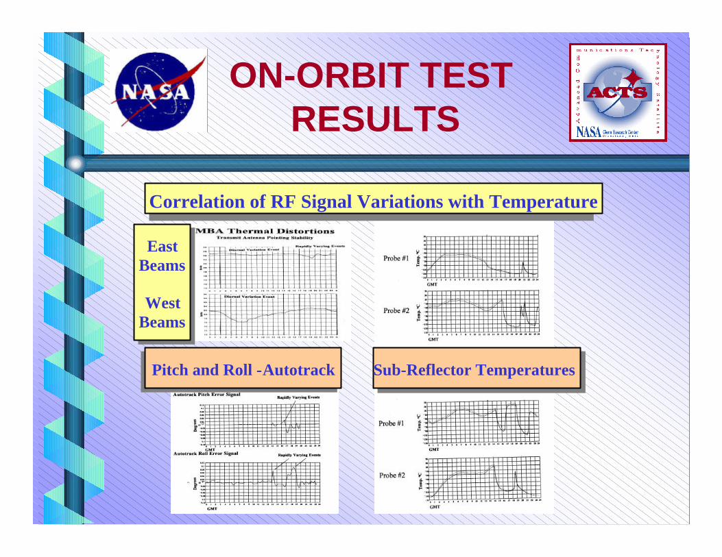
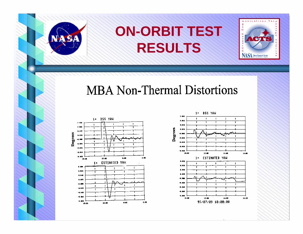
ON-ORBIT TEST RESULTS
Sub-Reflector TemperaturesSub-Reflector TemperaturesPitch and Roll - AutotrackPitch and Roll - Autotrack
EastBeams
WestBeams
EastBeams
WestBeams
Correlation of RF Signal Variations with TemperatureCorrelation of RF Signal Variations with Temperature

Sub-Reflector TemperaturesSub-Reflector TemperaturesPitch and Roll - AutotrackPitch and Roll - Autotrack
EastBeams
WestBeams
EastBeams
WestBeams
ON-ORBIT TESTRESULTS

Pitch Angle (East-West)Pitch Angle (East-West)Roll Angle (North- South)Roll Angle (North- South)
ON-ORBIT TESTRESULTS

ON-ORBIT TESTRESULTS
ON-ORBIT TESTRESULTS

ON-ORBIT TESTRESULTS

• Provide means of easily offsetting the S/C in pitch and roll to establish beam centers
•Continuous yaw sensing (vs. estimating) and a more direct yaw & roll control (momentum wheel vs. torquers) should be considered for precise spot beam
•Perform a careful; thermal distortion analysis for narrow spot beam antenna systems (Beam wondering may occur at other than at
maximum temperature gradients or extremes)
• Conduct low frequency dynamic analysis to ensure structural members do not cause spot beam wondering
(Micro disturbances from spacecraft control system can cause large antennas to oscillate)
• For separate transmit and receive antenna systems, provide a means for adjustingreceive and transmit beam alignments
ACTS LESSONSLEARNED

Small Beam TechnologySmall Beam Technology
Small Beam Technology (Light weight, low cost). Higher ratesusing GEO Satellites will require small spot beams (<1.0° ).
- ACTS utilizes 0.3 ° spot beams but had difficulties with thermaldistortions and antenna systems weights. (>30 lb/sq. m)
Reflector Antenna Technology• Antenna Modeling - Thermal• Light Weight , < 20 lb/sq. m.• Low Cost• Gridded reflector technology• BFN SW < 1 msec• Thermally Stable Ref., Structures
Future Ka-Band Systems