+K8U-X Front Matter Estatic.highspeedbackbone.net/pdf/Asus_K8U-X_Manual.pdf · ASUS K8U-X...
80
Motherboard K8U-X User Guide
Transcript of +K8U-X Front Matter Estatic.highspeedbackbone.net/pdf/Asus_K8U-X_Manual.pdf · ASUS K8U-X...

Mot
herb
oardK8U-X
User Guide

ii
E2010
No part of this manual, including the products and software described in it, may be reproduced, transmitted, transcribed, stored in a retrieval system, or translated into any language in any form or by any means, except documentation kept by the purchaser for backup purposes, without the express written permission of ASUSTeK COMPUTER INC. (“ASUS”).Product warranty or service will not be extended if: (1) the product is repaired, modified or altered, unless such repair, modification of alteration is authorized in writing by ASUS; or (2) the serial number of the product is defaced or missing.ASUS PROVIDES THIS MANUAL “AS IS” WITHOUT WARRANTY OF ANY KIND, EITHER EXPRESS OR IMPLIED, INCLUDING BUT NOT LIMITED TO THE IMPLIED WARRANTIES OR CONDITIONS OF MERCHANTABILITY OR FITNESS FOR A PARTICULAR PURPOSE. IN NO EVENT SHALL ASUS, ITS DIRECTORS, OFFICERS, EMPLOYEES OR AGENTS BE LIABLE FOR ANY INDIRECT, SPECIAL, INCIDENTAL, OR CONSEQUENTIAL DAMAGES (INCLUDING DAMAGES FOR LOSS OF PROFITS, LOSS OF BUSINESS, LOSS OF USE OR DATA, INTERRUPTION OF BUSINESS AND THE LIKE), EVEN IF ASUS HAS BEEN ADVISED OF THE POSSIBILITY OF SUCH DAMAGES ARISING FROM ANY DEFECT OR ERROR IN THIS MANUAL OR PRODUCT.SPECIFICATIONS AND INFORMATION CONTAINED IN THIS MANUAL ARE FURNISHED FOR INFORMATIONAL USE ONLY, AND ARE SUBJECT TO CHANGE AT ANY TIME WITHOUT NOTICE, AND SHOULD NOT BE CONSTRUED AS A COMMITMENT BY ASUS. ASUS ASSUMES NO RESPONSIBILITY OR LIABILITY FOR ANY ERRORS OR INACCURACIES THAT MAY APPEAR IN THIS MANUAL, INCLUDING THE PRODUCTS AND SOFTWARE DESCRIBED IN IT.Products and corporate names appearing in this manual may or may not be registered trademarks or copyrights of their respective companies, and are used only for identification or explanation and to the ownersʼ benefit, without intent to infringe.
Copyright© 2005 ASUSTeK COMPUTER INC. All Rights Reserved
First Edition V1 July 2005

iiiASUS K8U-X Motherboard
ContentsNotice ................................................................................................................ viSafety Information ............................................................................................ vii
Electrical safety ...................................................................................... viiOperation safety ..................................................................................... vii
About This Guide .............................................................................................viiiLayout in this guide ................................................................................viiiConventions used in this guide ..............................................................viiiWhere to find more information ..............................................................viii
K8U-X specifications summary ......................................................................... ix
Chapter 1: Product introduction1.1 Welcome! ..................................................................................................1-21.2 Package Contents .....................................................................................1-21.3 Special Features ......................................................................................1-2
1.3.1 Product highlights .........................................................................1-21.3.2 Unique ASUS features .................................................................1-4
1.4 Before You Proceed .................................................................................1-5Onboard LED ........................................................................................1-5
1.5 Motherboard Overview ..............................................................................1-61.5.1 Motherboard layout ......................................................................1-61.5.2 Placement direction ......................................................................1-71.5.3 Screw holes ..................................................................................1-7
1.6 Central Processing Unit (CPU) .................................................................1-81.6.1 Overview ......................................................................................1-81.6.2 Installing the CPU ........................................................................1-9
1.7 System Memory .....................................................................................1-101.7.1 DIMM sockets location ...............................................................1-101.7.2 Memory configurations ..............................................................1-101.7.3 Installing a DIMM ......................................................................1-13
1.8 Expansion Slots ......................................................................................1-131.8.1 Standard interrupt assignments .................................................1-141.8.2 IRQ assignments for this motherboard .....................................1-141.8.3 PCI slots ....................................................................................1-151.8.4 AGP SlotDIMM sockets location ................................................1-15
iv
1.9 Jumpers ..................................................................................................1-161.10 Connectors ............................................................................................1-181.10.1 Rear panel connectors .......................................................................1-181.10.2 Internal connectors .............................................................................1-20
Chapter 2: BIOS Information2.1 Managing and Updating Your BIOS ..........................................................2-2
2.1.1 Creating a bootable floppy disk ....................................................2-22.1.2 Using AFUDOS to update the BIOS .............................................2-32.1.3 Using AFUDOS to copy BIOS from PC ........................................2-42.1.4 Using ASUS EZ Flash to update the BIOS ..................................2-52.1.5 Recovering the BIOS with CrashFree BIOS 2 .............................2-6
2.2 BIOS Setup Programm .............................................................................2-82.2.1 BIOS menu screen .......................................................................2-92.2.2 Menu bar ......................................................................................2-92.2.3 Navigation keys ...........................................................................2-92.2.4 Menu items ................................................................................2-102.2.5 Sub-menu items .........................................................................2-102.2.6 Configruation .............................................................................2-102.2.7 Pop-up window ...........................................................................2-102.2.8 Scroll bar ....................................................................................2-102.2.9 General help ...............................................................................2-10
2.3 Main Menu .............................................................................................2-112.3.1 System Time .............................................................................2-112.3.2 System Date ..............................................................................2-112.3.3 Legacy Diskeete A, B ................................................................2-112.3.4 Primary/Secondary/Third/Fourth IDE Master/Slave ...................2-122.3.5 System Information ....................................................................2-13
2.4 Advanced Menu ......................................................................................2-142.4.1 JumperFree Configuration .........................................................2-142.4.2 CPU Configuration .....................................................................2-152.4.3 Chipset .......................................................................................2-162.4.4 Onboard Devices Configuration .................................................2-212.4.5 PCI PnP .....................................................................................2-22
2.5 Power Menu ............................................................................................2-242.5.1 Suspend Mode ..........................................................................2-24
vASUS K8U-X Motherboard
2.5.2 Repost Video on S3 Resume ....................................................2-242.5.3 ACPI 2.0 Support ......................................................................2-242.5.4 ACPI APIC Support ...................................................................2-242.5.5 APM Configuration .....................................................................2-252.5.6 Hardware Monitor .......................................................................2-27
2.6 Boot Menu ...............................................................................................2-282.6.1 Boot Device Priority ...................................................................2-282.6.2 Hard Disk Drives ........................................................................2-282.6.3 Boot Settings Configuration .......................................................2-292.6.4 Security ......................................................................................2-30
2.7 Exit Menu ................................................................................................2-32
Chapter 3: Software support3.1 Install an Operating System ......................................................................3-23.2 Support CD Information ............................................................................3-2
3.2.1 Running the support CD ...............................................................3-23.2.2 Drivers menu ................................................................................3-33.2.3 Utilities menu ................................................................................3-43.2.4 Manual menu ...............................................................................3-53.2.5 ASUS Contact Information ...........................................................3-6
3.3 RAID Configurations .................................................................................3-73.3.1 Installing hard disks ......................................................................3-7
3.4 Creating a VIA RAID Driver Disk ...............................................................3-83.5 Cool ʻnʼ Quiet!™ Technology .....................................................................3-9
3.5.1 Opening Cool ʻnʼ Quiet!™ Technology .........................................3-93.5.2 Running Cool ʻnʼ Quiet!™ Software ..........................................3-11
vi
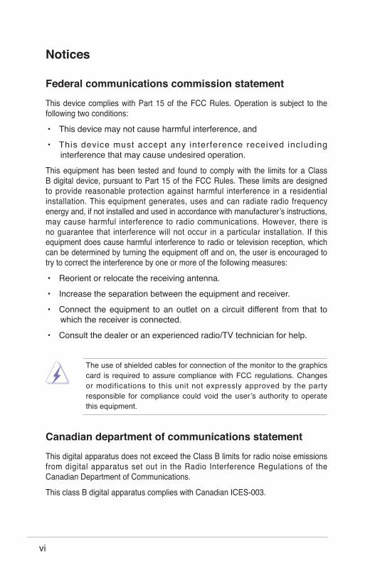
The use of shielded cables for connection of the monitor to the graphics card is required to assure compliance with FCC regulations. Changes or modifications to this unit not expressly approved by the party responsible for compliance could void the userʼs authority to operate this equipment.
Notices
Federal communications commission statement
This device complies with Part 15 of the FCC Rules. Operation is subject to the following two conditions:
• This device may not cause harmful interference, and
• This device must accept any interference received including interference that may cause undesired operation.
This equipment has been tested and found to comply with the limits for a Class B digital device, pursuant to Part 15 of the FCC Rules. These limits are designed to provide reasonable protection against harmful interference in a residential installation. This equipment generates, uses and can radiate radio frequency energy and, if not installed and used in accordance with manufacturerʼs instructions, may cause harmful interference to radio communications. However, there is no guarantee that interference will not occur in a particular installation. If this equipment does cause harmful interference to radio or television reception, which can be determined by turning the equipment off and on, the user is encouraged to try to correct the interference by one or more of the following measures:
• Reorient or relocate the receiving antenna.
• Increase the separation between the equipment and receiver.
• Connect the equipment to an outlet on a circuit different from that to which the receiver is connected.
• Consult the dealer or an experienced radio/TV technician for help.
Canadian department of communications statement
This digital apparatus does not exceed the Class B limits for radio noise emissions from digital apparatus set out in the Radio Interference Regulations of the Canadian Department of Communications.
This class B digital apparatus complies with Canadian ICES-003.

viiASUS K8U-X Motherboard
Safety Information
Electrical safety
• To prevent electrical shock hazard, disconnect the power cable from the electrical outlet before relocating the system.
• When adding or removing devices to or from the system, ensure that the power cables for the devices are unplugged before the signal cables are connected. If possible, disconnect all power cables from the existing system before you add a device.
• Before connecting or removing signal cables from the motherboard, ensure that all power cables are unplugged.
• Seek professional assistance before using an adapter or extension cord. These devices could interrupt the grounding circuit.
• Make sure that your power supply is set to the correct voltage in your area. If you are not sure about the voltage of the electrical outlet you are using, contact your local power company.
• If the power supply is broken, do not try to fix it by yourself. Contact a qualified service technician or your retailer.
Operation safety• Before installing the motherboard and adding devices on it, carefully
read all the manuals that came with the package.
• Before using the product, make sure all cables are correctly connected and the power cables are not damaged. If you detect any damage, contact your dealer immediately.
• To avoid short circuits, keep paper clips, screws, and staples away from connectors, slots, sockets and circuitry.
• Avoid dust, humidity, and temperature extremes. Do not place the product in any area where it may become wet.
• Place the product on a stable surface.
• If you encounter technical problems with the product, contact a qualified service technician or your retailer.
viii
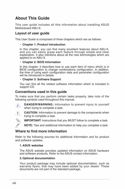
DANGER/WARNING: Information to prevent injury to yourself when trying to complete a task.CAUTION: Information to prevent damage to the components when trying to complete a task.
NOTE: Tips and additional information to help you complete a task.IMPORTANT: Instructions that you MUST follow to complete a task.
Conventions used in this guideTo make sure that you perform certain tasks properly, take note of the following symbols used throughout this manual.
About This GuideThis user guide includes all tthe information about installing ASUS Motherboard K8U-X.
Layout of user guideThis User Guide is composed of three chapters which are as follows:
• Chapter 1: Product IntroductionIn this chapter, you can find many excellent features about K8U-X, and you can easily grasp each feature through simple and clear explanation. It also mentions about all the new technologies which are applied to on K8U-X.• Chapter 2: BIOS InformationIn this chapter, it describes how to use each item of menu which is in BIOS configuration to change combinations configuration. In addition, the time of using each configuration data and parameter configuration will be introduced in details.• Chapter 3: Software SupportYou can find all the related software information which is included in support CD.
Where to find more informationRefer to the following sources for additional information and for product and software updates.
1. ASUS websites
The ASUS website provides updated information on ASUS hardware and software products. Refer to the ASUS contact information.2. Optional documentation
Your product package may include optional documentation, such as warranty flyers, that may have been added by your dealer. These documents are not part of the standard package.

ixASUS K8U-X Motherboard
K8U-X Specifications Summary
CPU Socket 754 for AMD Athlon 64 / Sempron CPU Support AMD 64 architecture that enables simultaneous 32-biit and 64-bit computing Supports AMD Cool 'n' Quiet Technology
Chipset ULi M1689
System bus 800 MHz (1600 MT/s)
Memory 2 x 184-pin DIMM Sockets support up to 2GB PC3200/PC2700/PC2100 non-ECC un-buffered DDR SDRAM memory
Expansion slots 1 x AGP 8X 4 x PCI
Storage 2 x UltraATA 133/100 2 x SATA with RAID 0, RAID 1and JBOD
Audio ADI AD1888 SoundMAX 6-channel audio Codec support for S/PDIF out interfafce
Lan Realtek 8201CL 10/100 Mbps Ethernet Controller
USB 8 USB 2.0/1.1 ports
Overclocking SFS (Stepless Frequency Selection) from 200 MHz up to 300 MHz at 1 MHz increment
Adjustable FSB/DDR ratio ASUS JumperFree ASUS C.P.R. (CPU Parameter Recall)
ASUS EZ FlashSpecial features ASUS CrashFree BIOS2 ASUS MyLogoTM AMD Cool ʻnʼ QuietTM Technology
Back panel I/O 1 x Parallel port 1 x Serial port 1 x PS/2 keyboard port 1 x PS/2 mouse port 4 x USB 2.0 ports 1 x S/PDIF out 1 x RJ-45 Line In/Line Out/Microphone ports

x
K8U-X Specifications Summary
Internal I/O 2 x USB 2.0 connectors for 4 additional USB 2.0 Ports CPU/Chassis fan connectors 20-pin ATX/4-pin ATX 12V power connectors CD/AUX audio in connectors Front panel audio connector System pannel connector GAME/MIDI connector Chassis intrusion
BIOS features 4Mb Flash EEPROM AMI BIOS, ACPI, PnP, DMI2.0, WfM 2.0, SM BIOS
2.3, ASUS EZ Flash, CrashFree BIOS 2
Industry standard PCI 2.2, USB 2.0/1.1
Manageability WOL by PME, WOR by PME
Power Requirement ATX power supply (with 20-pin and 4-pin 12V plugs) ATX 12V 2.0 compliant
Form Factor ATX form factor: 12 in x 7 in (30.5 cm x 17.8 cm)
Support CD contents Device drivers ASUS PC Probe Anti-virus utility (OEM Version)

This chapter describes the features of the motherboard. It includes brief descriptions of the motherboard components, and illustrations of the layout, jumper settings, and connectors.
Product Introduction
Chapter 1
Chapter 1: Product Introduction1-2
1.1 Welcome!Thank you for buying the ASUS® K8U-X motherboard!
The motherboard delivers a host of new features and latest technologies making it another standout in the long line of ASUS quality motherboards!
The motherboard combines the powers of the AMD Athlon™ 64 processor and the ULi M1689 chipset to set a new benchmark for an effective desktop platform solution.
Supporting up to 2GB of system memory with PC3200/PC2700/PC2100/PC1600 DDR SDRAM, high-resolution graphics via an AGP 8X slot, Serial ATA RAID, USB 2.0, and 6-channel audio features, the motherboard takes you ahead in the world of power computing!
Before you start installing the motherboard, and hardware devices on it, check the items in your package with the list below.
If any of the above items is damaged or missing, contact your retailer.
1.2 Package ContentsCheck your motherboard package for the following items.
ASUS K8U-X motherboardASUS motherboard support CD1 x Ultra DMA 133/100/66 cables1 x Serial ATA cables1 x Serial ATA power cables1 x 3.5” Floppy disk cableI/O shieldUser guide
1.3 Special Features1.3.1 Product HighlightsLatest processor technologyThe AMD Athlon™ 64 desktop processor is based on AMDʼs 64-bit architecture, which represents the landmark introduction of the industryʼs first x86-64 technology. This processor provides a dramatic leap forward in compatibility, performance, investment protection, and reduced total cost of ownership and development.
ASUS K8U-X Motherboard 1-3
HyperTransport™ TechnologyHyperTransport™ Technology is a high-speed, low latency, point-to-point link designed to increase the communication speed between integrated circuits in computers, networking and telecommunicatons equipment up to 48 times faster than other existing technologies.
Cool ʻn ̓Quiet!™ TechnologyThe motherboard supports the AMD® Cool ʻnʼ Quiet!™ Technology that dynamically and automatically changes the CPU speed, voltage and amount of power depending on the task the CPU performs.
Serial ATA solutionThe motherboard supports two interfaces compliant to the Serial ATA (SATA) specification, an evolutionary replacement of the Parallel ATA storage interface. The Serial ATA specification allows for thinner, more flexible cables with lower pin count, reduced voltage requirement, up to 150 MB/s data transfer rate.
Serial ATA RAID solutionThe motherboard provides a high-performance Serial ATA RAID controller that enhance hard disk performance and data backup protection without the cost of additional RAID cards. The onboard ULI M1689 RAID controller provides two Serial ATA connectors for RAID 0, 1 and JBOD functions.
AGP 8X supportAGP 8X (AGP 3.0) is the VGA interface specification that enables enhanced graphics performance with maximum bandwidth speeds of up to 2.12 GB/s.
S/PDIF outThe motherboardʼs S/PDIF out function turns your computer into a high-end entertainment system with digital connectivity to powerful speaker systems.
USB 2.0 technologyThe motherboard implements the new Universal Serial Bus (USB) 2.0 specification, extending the connection speed from 12 Mbps on USB 1.1 to a fast 480 Mbps on USB 2.0 - supporting up to eight USB 2.0 ports. The higher bandwidth of USB 2.0 allows connection of devices such as high resolution video conferencing cameras, next generation scanners and printers, and fast storage units. USB 2.0 is backward compatible with USB 1.1.

Chapter 1: Product Introduction1-4
6-Channel Audio solution The motherboard uses an onboard audio CODEC that lets you enjoy high-quality 6-channel audio without having to buy advanced sound cards.
1.3.2 Unique ASUS features CrashFree BIOS 2This feature allows you to restore the original BIOS data from the ASUS support CD in case when the BIOS codes and data are corrupted. This protection eliminates the need to buy a replacement ROM chip. See page 2-6.
C.P.R. (CPU Parameter Recall)The C.P.R. feature of the motherboard BIOS allows automatic re-setting to the BIOS default settings in case the system hangs due to overclocking. When the system hangs due to overclocking, C.P.R. eliminates the need to open the system chassis and clear the RTC data. Simply shut down and reboot the system, and BIOS automatically restores the CPU previous setting for each parameter.
ASUS MyLogo™This new feature present in the motherboard allows you to personalize and add style to your system with customizable boot logos. See pages 2-31.
ASUS EZ Flash BIOSWith the ASUS EZ Flash, you can easily update the system BIOS even before loading the operating system. No need to use a DOS-based utility or boot from a floppy disk. See page 2-5.
ASUS K8U-X Motherboard 1-5
1.4 Before You ProceedTake note of the following precautions before you install motherboard components or change any motherboard settings.
K8U
-X
®
K8U-X Onboard LED
SB_PWR
ONStandbyPower
OFFPowered
Off
1. Unplug the power cord from the wall socket before touching any component.
2. Use a grounded wrist strap or touch a safely grounded object or to a metal object, such as the power supply case, before handling components to avoid damaging them due to static electricity.
3. Hold components by the edges to avoid touching the ICs on them.
4. Whenever you uninstall any component, place it on a grounded antistatic pad or in the bag that came with the component.
5. Before you install or remove any component, ensure that the ATX power supply is switched off or the power cord is detached from the power supply. Failure to do so may cause severe damage to the motherboard, peripherals, and/or components.
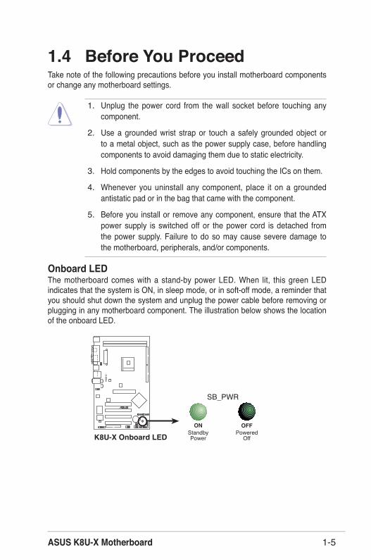
Onboard LEDThe motherboard comes with a stand-by power LED. When lit, this green LED indicates that the system is ON, in sleep mode, or in soft-off mode, a reminder that you should shut down the system and unplug the power cable before removing or plugging in any motherboard component. The illustration below shows the location of the onboard LED.

Chapter 1: Product Introduction1-6
1.5 Motherboard Overview1.5.1 Motherboard layout
K8U
-X
R
PCI1
PANEL
K8U
-X
R
CR2032 3VLithium Cell
CMOS Power
CD
AUX
Supe
rI/O
4MbitBIOS
Accelerated Graphics Port (AGP)FP_AUDIO
ADIAD1888
ATX12V
CH
ASSI
SC
LRTC
ATXP
WR
USB56
SB_P
WR
CHA_FAN
USB
PW12
USB
PW34
USBPW56USBPW78
18.3cm (7in)
30.5
cm (1
2in)
SATA1
FLOPPY
ULIM1689
USB78
SATA2
CPU_FAN
PAR
ALL
EL P
OR
T
COM1
SPDIF_O
PS/2KBMST: MouseB: Keyboard
Below:Mic InCenter:Line OutTop:Line In
F_USB12
RJ-45Top:USB3
USB4
Bottom:
DDR DIMM1 (64 bit,184-pin module)DDR DIMM2 (64 bit,184-pin module)
Socket 754
PCI2
PCI3
PCI4
RTL8201CL
PRI_
IDE
SEC
_ID
E
GAME
ASUS K8U-X Motherboard 1-7
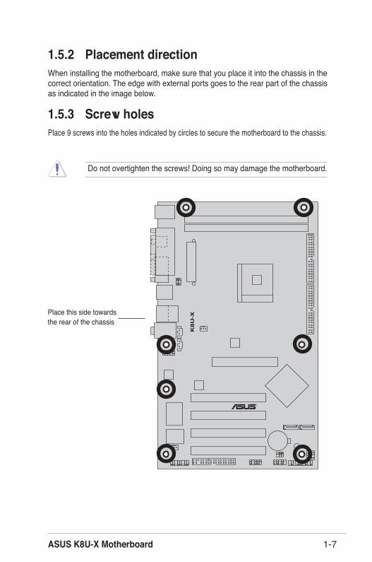
1.5.2 Placement directionWhen installing the motherboard, make sure that you place it into the chassis in the correct orientation. The edge with external ports goes to the rear part of the chassis as indicated in the image below.
1.5.3 Screw holesPlace 9 screws into the holes indicated by circles to secure the motherboard to the chassis.
Do not overtighten the screws! Doing so may damage the motherboard.
Place this side towards the rear of the chassis
K8U
-X
®
Chapter 1: Product Introduction1-8
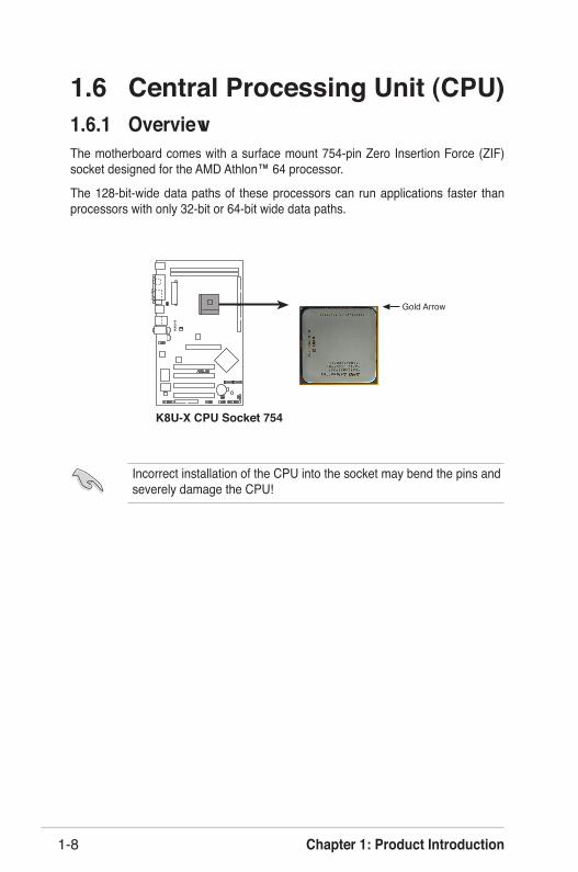
1.6 Central Processing Unit (CPU)1.6.1 OverviewThe motherboard comes with a surface mount 754-pin Zero Insertion Force (ZIF) socket designed for the AMD Athlon™ 64 processor.
The 128-bit-wide data paths of these processors can run applications faster than processors with only 32-bit or 64-bit wide data paths.
Incorrect installation of the CPU into the socket may bend the pins and severely damage the CPU!
K8U
-X
®
K8U-X CPU Socket 754
Gold Arrow
ASUS K8U-X Motherboard 1-9
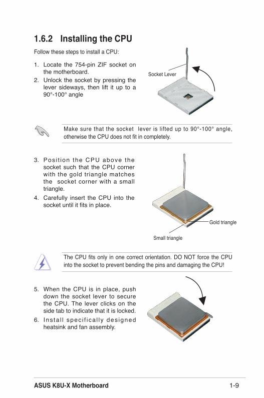
1.6.2 Installing the CPUFollow these steps to install a CPU:
1. Locate the 754-pin ZIF socket on the motherboard. Socket Lever
2. Unlock the socket by pressing the lever sideways, then lift it up to a 90°-100° angle
Make sure that the socket lever is lifted up to 90°-100° angle, otherwise the CPU does not fit in completely.
3. Pos i t ion the CPU above the socket such that the CPU corner with the gold triangle matches the socket corner with a small triangle.
4. Carefully insert the CPU into the socket until it fits in place.
The CPU fits only in one correct orientation. DO NOT force the CPU into the socket to prevent bending the pins and damaging the CPU!
5. When the CPU is in place, push down the socket lever to secure the CPU. The lever clicks on the side tab to indicate that it is locked.
6. Ins ta l l spec i f i ca l l y des igned heatsink and fan assembly.
Gold triangle
Small triangle

Chapter 1: Product Introduction1-10
1.7 System Memory1.7.1 DIMM sockets locationThe following figure illustrates the location of the DDR DIMM sockets.
K8U
-X
®
K8U-X 184-pin DDR DIMM sockets
80 Pins104 Pins
DIMM1
DIMM2
1.7.2 Memory configurationsYou may install 64MB, 128MB, 256MB, 512MB DDR DIMMs into the DIMM sockets using the memory configurations in this section.
1. Install ing DDR DIMMs other than the recommended configurations may cause memory sizing error or system boot failure. Use any of the recommended configurations in Table 1.
2. For optimum compatibility, obtain memory modules from qualified vendors. See Qualified Vendors List on page 1-11.
3. Always install DIMMs with the same CAS Latency. For optimum
compatibility, obtain memory modules from the same vendors. See Qualified Vendors List on page 1-11.
4. Obtain DDR DIMMs only from ASUS qualified vendors for better system performance.
Important notes
Make sure to unplug the power supply before adding or removing DIMMs or other system components. Failure to do so may cause severe damage to both the motherboard and the components.

ASUS K8U-X Motherboard 1-11
DDR400 Qualified Vendor List (QVL) Size Vendor Part Number Chip Brand SS/DS Chip Number DIMMs A* B*256MB Kingston KVR333X64C25/256 Kingston SS D3208DH1T-6 V V256MB Kingston KVR333X64C25/256 Hynix SS HY5DU56822BT-J V V512MB Kingston KVR333X64C25/512 Hynix DS HY5DU56822BT-D43 V V512MB Kingston KVR333X64C25/512 Hynix DS HY5DU56822BT-J V V512MB Kingston KVR400X64C3A/512 Hynix DS HY5DU56822BT-D43 V V512MB Kingston KVR400X64C3A/512 Kingston DS D3208DH1T-5 V V256MB Kingston KVR400X64C3A/256 Hynix SS HY5DU56822BT-D43 V V256MB Infineon HYS64D32300GU-5-C Infineon SS HYB25D256800CE-5C V V512MB Infineon HYS64D64320GU-5-C Infineon DS HYB25D256800CE-5C V V256MB Infineon HYS64D32300GU-5-C Infineon SS HYB25D256800CE-5C V V512MB Infineon HYS64D64320GU-6-C Infineon DS HYB25D256800CE-6C V V256MB HY DDR400-256 Hynix SS HY5DU56822BT-D43 V V512MB HY DDR400-512 Hynix DS HY5DU56822BT-D43 V V256MB HY DDR266-256 Hynix SS HY5DU56822AT-H V V256MB HY DDR333-256 Hynix SS HY5DU56822BT-J V V512MB HY DDR333-512 Hynix DS HY5DU56822BT-J V V256MB Corsair VS256MB400 Value select SS VS32M8-5 2B0409 V V512MB Corsair VS512MB400 Value select DS VS32M8-5 2B0402 V V256MB Corsair VS256MB333 Samsung SS K4H5608380-TCB3 V V512MB Corsair VS512MB333 Value select DS VS32M8-6 2B0412 V V512MB Micron MT16VDDT6464AG-335GB Micron DS MT46V32M8TG-6TG V V256MB Micron MT8VDDT3264AG-335GB Micron SS MT46V32M8TG-6TG V V256MB Micron MT8VDDT3264AG-40BGB Micron SS MT46V32M8TG-5BG V V512MB Micron MT16VDDT6464AG-40BCB Micron DS MT46V32M8TG-5BC V V256MB Samsung M368L3223FTN-CCC Samsung SS K4H560838F-TCCC V V512MB Samsung M368L6423FTN-CCC Samsung DS K4H560838F-TCCC V V256MB Samsung M368L3223FTN-CB3 Samsung SS K4H560838F-TCB3 V V512MB Samsung M368L6423FTN-CB3 Samsung DS K4H560838F-TCB3 V V256MB Winbond U24256ADWBG6H20 Winbond SS W942508CH-5 V V256MB Winbond U24256AAWBG6H20 Winbond SS W942508CH-6 V V512MB Winbond DDR333-512 Winbond DS W942508BH-6 V V512MB Winbond U24512ADWBG6H20 Winbond DS W942508CH-5 V V256MB Elpida U24256ADEPG6H20 Elpida SS DD2508AKTA-5C V 512MB Elpida U24512ADEPG6H20 Elpida DS DD2508AMTA V V256MB Transcend DDR400-256 Samsung SS K4H560838F-TCCC V V256MB Transcend DDR400-256 Mosel SS V58C2256804SAT5B V V512MB Transcend DDR400-512 Mosel DS V58C2256804SAT5B V V512MB Transcend DDR400-512 Hynix DS HY5DU56822CT-D43 V V256MB Transcend DDR333-256 Mosel SS V58C2256804SAT6 V V256MB Transcend DDR333-256 Winbond SS W942508CH-6 V V512MB Transcend DDR333-512 Hynix DS HY5DU56822CT-J V V256MB Pmi 3208GATA07-04A7 Pmi SS PM4D328D50406EU V V512MB Pmi 3208GATA01-04A4 Pmi DS PM4D328S50403DU V V256MB Kingmax MPMB62D-38LT3R Mosel SS V58C2256804SAT6 V V512MB Kingmax MPMC22D-38HT3R Hynix DS HY5DU56822BT-J V V256MB Kingmax MPXB62D-38KT3R Kingmax SS KDL388P4LA-50 V V512MB Kingmax MPXC22D-38KT3R Kingmax DS KDL388P4EA-50 V V256MB Mosel V826632K24SATG-D3 Mosel SS V58C2256804SAT5 V V512MB Mosel V826664K24SATG-D3 Mosel DS V58C2256804SAT5 V V256MB Nanya NT256D64S88B1G-6K Nanya SS NT5DS32M8BT-6K V V256MB Nanya NT256D64S88B1G-5T Nanya SS NT5DS32M8BT-5T V V

Chapter 1: Product Introduction1-12
A* supports one module inserted in any slot.B* supports one pair of modules inserted in two slots.
Visit the ASUS website (www.asus.com) for the latest DDR 400 Qualified Vendor List for this motherboard.
Size Vendor Part Number Chip Brand SS/DS Chip Number DIMMs A* B*512MB Nanya NT512D64S8HB1G-5T Nanya DS NT5DS32M8BT-5T V V512MB Apacer 77.90728.U1G Apacer DS AM3A568AJT-6B V V512MB Apacer 77.10736.464 Samsung DS K4H560838E-TCCC V V256MB Apacer 77.10636.46G Samsung SS K4H560838E-TCCC V V256MB Apacer 77.10628.56G Mosel SS V58C2256804SAT6 V V256MB Apacer 77.10628.112 Infineon SS HYB25D256800BT-6B V V256MB Apacer 77.10636.56G Mosel SS V58C2256804SAT5B V V512MB Apacer 77.10736.11G Infineon DS HYB25D256800BT-5B V V256MB Smart U24256ADSRG6H20 Smart SS D32M8XS50H3X4AMV V V256MB Smart U24256ADSRG6H20 Smart SS D32M8XS60HBX4AMV V V512MB Smart U24512ADSRG6H20 Smart DS D32M8XS50H3X4AMV V V512MB Smart U24512ADSRG6H20 Smart DS D32M8XS60HBX4AMV V V256MB Twinmos DDR333-256 Twinmos SS TMD7608F8E60B V V1G Twinmos M2S5016AJAMC5G0811A-J Micron DS MT46V64M8TG-6T V V256MB Twinmos M2S9109BFAPS9F0811A-T PSC SS A2S56D30ATP V V512MB Twinmos M2S9J18BGAPS9F0811A-T PSC DS A2S56D30ATP V V1G Twinmos M2SA016AJAHXAG0811A-T Hynix DS HY5DU12822AT-D43 V 256MB A Data MDOSS1F3G3X10BZL0Z Samsung SS K4H560838E-TCC5 V V512MB A Data MDOSS1F3H4X10BZL0Z Samsung DS K4H560838E-TCC5 V V

ASUS K8U-X Motherboard 1-13
1.8 Expansion SlotsTo install and configure an expansion card:
1. Install an expansion card following the instructions that came with the chassis.2. Turn on the system and change the necessary BIOS settings, if any.
See Chapter 2 for BIOS information.3. Assign an IRQ to the card. Refer to the tables next page.4. Install the drivers and/or software applications for the expansion card
according to the card documentation.
A DDR DIMM is keyed with a notch so that it fits in only one direction. DO NOT force a DIMM into a socket to avoid damaging the DIMM.
1.7.3 Installing a DIMM
1. Unlock a DIMM socket by pressing the retaining clips outward.
2. A l ign a DIMM on the socket such that the notch on the DIMM matches the break on the socket.
3. Firmly insert the DIMM into the socket until the retaining clips snap back in place and the DIMM is properly seated.
Unlocked
Follow these steps to install a DIMM.
Make sure to unplug the power supply before adding or removing DIMMs or other system components. Failure to do so may cause serve damage to both the motherboard and the components.

Chapter 1: Product Introduction1-14
IRQ Priority Standard Function 0 1 System Timer 1 2 Keyboard Controller 2 N/A Programmable Interrupt 3* 11 IRQ holder for PCI steering 4* 12 Communications Port (COM1) 5* 13 IRQ holder for PCI steering 6 14 Floppy Disk Controller 7* 15 Printer Port (LPT1) 8 3 System CMOS/Real Time Clock 9* 4 IRQ holer for PCI steering 10* 5 IRQ holer for PCI steering 11* 6 IRQ holer for PCI steering 12* 7 PS/2 Compatible Mouse Port 13 8 Numeric Data Processor 14* 9 Primary IDE Channel 15* 10 Secondary IDE Channel
1.8.1 Standard interrupt assignments
*﹛These IRQs are usually available for ISA or PCI devices.
When using PCI cards on shared slots, ensure that the drivers support “Share IRQ” or that the cards do not need IRQ assignments. Otherwise, conflicts will arise between the two PCI groups, making the system unstable and the card inoperable.
1.8.2 IRQ assignments for this motherboard INT A INT B INT C INT DPCI slot 1 shared - - -PCI slot 2 - shared - -PCI slot 3 - - shared -PCI slot 4 - - - usedInternal USB 2.0 controller shared shared shared shared10/100 LAN - shared - -AGP slot shared - - -

ASUS K8U-X Motherboard 1-15
Install only +1.5V AGP cards.
1.8.4 AGP slotThe Accelerated Graphics Port (AGP) slot supports AGP 8X/4X (+1.5V) cards. When you buy an AGP card, make sure that you ask for one with +1.5V specification.
Note the notches on the card golden fingers to ensure that they fit the AGP slot on the motherboard.
K8U
-X
®
K8U-X Accelerated Graphics Port (AGP)
Keyed for 1.5v
1.8.3 PCI slotsThe PCI slots support PCI cards such as a LAN card, SCSI card, USB card, and other cards that comply with PCI specifications.
Chapter 1: Product Introduction1-16
1.9 JumpersThe onboard jumpers supply some configurations about special functions, in order to satisfy usersʼ requirements.
Except when clearing the RTC RAM, never remove the cap on the jumper default position. Removing the cap will cause system boot failure!
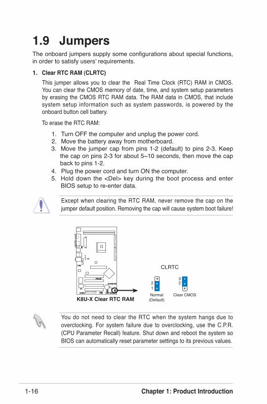
1. Clear RTC RAM (CLRTC)This jumper allows you to clear the Real Time Clock (RTC) RAM in CMOS. You can clear the CMOS memory of date, time, and system setup parameters by erasing the CMOS RTC RAM data. The RAM data in CMOS, that include system setup information such as system passwords, is powered by the onboard button cell battery.
To erase the RTC RAM:
1. Turn OFF the computer and unplug the power cord. 2. Move the battery away from motherboard.
3. Move the jumper cap from pins 1-2 (default) to pins 2-3. Keep the cap on pins 2-3 for about 5~10 seconds, then move the cap back to pins 1-2.
4. Plug the power cord and turn ON the computer.5. Hold down the <Del> key during the boot process and enter
BIOS setup to re-enter data.
K8U
-X
®
K8U-X Clear RTC RAM
CLRTC
Normal Clear CMOS(Default)
12 2
3
You do not need to clear the RTC when the system hangs due to overclocking. For system failure due to overclocking, use the C.P.R. (CPU Parameter Recall) feature. Shut down and reboot the system so BIOS can automatically reset parameter settings to its previous values.
ASUS K8U-X Motherboard 1-17
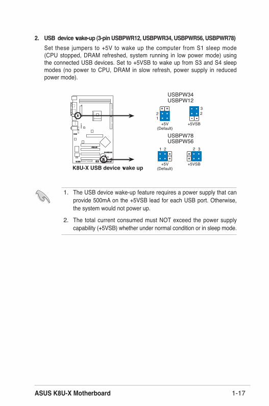
2. USB device wake-up (3-pin USBPWR12, USBPWR34, USBPWR56, USBPWR78)Set these jumpers to +5V to wake up the computer from S1 sleep mode (CPU stopped, DRAM refreshed, system running in low power mode) using the connected USB devices. Set to +5VSB to wake up from S3 and S4 sleep modes (no power to CPU, DRAM in slow refresh, power supply in reduced power mode).
K8U
-X
®
21
K8U-X USB device wake up
3221
+5V(Default)
+5VSB
USBPW56USBPW78
+5V(Default)
+5VSB
USBPW12USBPW34
32
1. The USB device wake-up feature requires a power supply that can provide 500mA on the +5VSB lead for each USB port. Otherwise, the system would not power up.
2. The total current consumed must NOT exceed the power supply capability (+5VSB) whether under normal condition or in sleep mode.

Chapter 1: Product Introduction1-18
1.10 ConnectorsThis section describes and illustrates the motherboard rear panel and internal connectors.
1.10.1 Rear panel connectors1
11
4
5
6
7
2 3
910 8
1. PS/2 mouse port. This green 6-pin connector is for a PS/2 mouse.2. Parallel port. This 25-pin port connects a parallel printer, a scanner, or
other devices.3. RJ-45 port. This port allows connection to a Local Area Network (LAN)
through a network hub. 4. Line In jack. This Line In (light blue) jack connects a tape player
or other audio sources. In 6-channel mode, the function of this jack becomes Bass/Center.
5. Line Out jack. This Line Out (lime) jack connects a headphone or a speaker. In 6-channel mode, the function of this jack becomes Front Speaker Out.
6. Microphone jack. This Mic (pink) jack connects a microphone. In 6-channel mode, the function of this jack becomes Rear Speaker Out.
The functions of the Line Out, Line In, and Microphone jacks change when you select the 6-channel audio configuration as shown in the following table.
Audio 2, 4 or 6-channel configuration
Headphone/2-Speaker
4-Speaker 6-Speaker
Light Blue Line in Line In Bass/CenterLime Line out Front Speaker Out Front Speaker OutPink Mic In Rear Speaker Out Rear Speaker Out
ASUS K8U-X Motherboard 1-19
7. USB 2.0 ports 3 and 4. These two 4-pin Universal Serial Bus (USB) ports are available for connecting USB 2.0 devices.
8. USB 2.0 ports 1 and 2. These two 4-pin Universal Serial Bus (USB) ports are available for connecting USB 2.0 devices.
9. Serial connector. This 9-pin COM1 port is for serial devices.10. S/PDIF out jack. This jack connects to external audio output devices.11. PS/2 keyboard port. This purple connector is for a PS/2 keyboard.

Chapter 1: Product Introduction1-20
1.10.2 Internal connectorsThis section describes and illustrates the internal connectors on the motherboard.
1. IDE connectors (40-1 pin PRI_IDE, SEC_IDE)This connector supports the provided UltraATA133 IDE hard disk ribbon cable. Connect the cableʼs blue connector to the primary (recommended) or secondary IDE connector, then connect the gray connector to the UltraATA133 slave device (hard disk drive) and the black connector to the UltraATA133 master device.
Note: Orient the red markings (usually zigzag) on the IDE ribbon cable to PIN 1.
K8U
-X
®
K8U-X IDE connectors
NOTE: Orient the red markings(usually zigzag) on the IDEribbon cable to PIN 1.
PRI_
IDE
PIN 1 SEC
_ID
E
PIN 1
1. Follow the hard disk drive documentation when setting the device in master or slave mode.
2. Pin 20 on each IDE connector is removed to match the covered hole on the UltraATA cable connector. This prevents incorrect orientation when you connect the cables.
3. The hole near the blue connector on the UltraATA cable is intentional.
ASUS K8U-X Motherboard 1-21
K8U
-X
R
K8U-X Floppy disk drive connector
FLOPPY
PIN 1
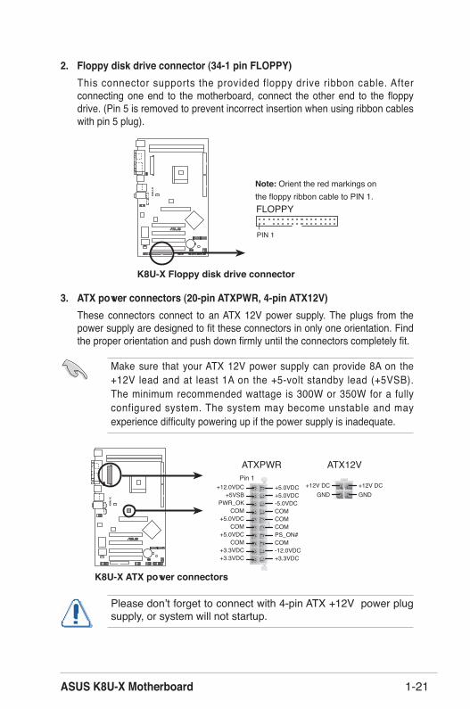
2. Floppy disk drive connector (34-1 pin FLOPPY)This connector supports the provided floppy drive ribbon cable. After connecting one end to the motherboard, connect the other end to the floppy drive. (Pin 5 is removed to prevent incorrect insertion when using ribbon cables with pin 5 plug).
Note: Orient the red markings on the floppy ribbon cable to PIN 1.
3. ATX power connectors (20-pin ATXPWR, 4-pin ATX12V)These connectors connect to an ATX 12V power supply. The plugs from the power supply are designed to fit these connectors in only one orientation. Find the proper orientation and push down firmly until the connectors completely fit.
K8U
-X
®
K8U-X ATX power connectors
ATXPWR ATX12VPin 1
+3.3VDC-12.0VDCCOMPS_ON#
COMCOM
COM-5.0VDC+5.0VDC+5.0VDC
PWR_OK
+12.0VDC
+3.3VDC+3.3VDC
COM
+5.0VDCCOM
+5.0VDC
COM
+5VSB+12V DC
GND+12V DCGND
Make sure that your ATX 12V power supply can provide 8A on the +12V lead and at least 1A on the +5-volt standby lead (+5VSB). The minimum recommended wattage is 300W or 350W for a fully configured system. The system may become unstable and may experience difficulty powering up if the power supply is inadequate.
Please donʼt forget to connect with 4-pin ATX +12V power plug supply, or system will not startup.

Chapter 1: Product Introduction1-22
5. CPU and chassis fan connectors (3-pin CPU_FAN, CHA_FAN)The fan connectors support cooling fans of 350mA~740mA (8.88W max.) or a total of 1A~2.22A (26.64W max.) at +12V. Connect the fan cables to the fan connectors on the motherboard, making sure that the black wire of each cable matches the ground pin of the connector.
Do not forget to connect the fan cables to the fan connectors. Lack of sufficient air flow within the system may damage the motherboard components. These are not jumpers! DO NOT place jumper caps on the fan connectors!
K8U
-X
®
K8U-X Fan connectors
CPU_FAN
CHA_FAN
GN
D
Rot
atio
n+1
2VG
ND
Rot
atio
n+1
2V
4. Internal audio connectors (4-pin CD, AUX)These connectors allow you to receive stereo audio input from sound sources such as a CD-ROM, TV tuner, or MPEG card.
K8U
-X
®
K8U-X Internal audio connectors
AUX (White)Right Audio Channel
Left Audio ChannelGround
CD (Black)Right Audio Channel
Left Audio ChannelGround

ASUS K8U-X Motherboard 1-23
6. USB header (10-1 pin USB56, USB78)If the USB ports on the rear panel are inadequate, a USB header is available for additional USB ports. Connect the USB cable of the USB 2.0 module to this header. You may install the USB module in the chassis front panel. The module has two USB 2.0 ports for connecting next generation USB peripherals such as high resolution cameras, scanners, and printers.
K8U
-X
®
K8U-X USB 2.0 connectors
USB56
USB
+5V
USB
_P6-
USB
_P6+
GN
DN
C
USB
+5V
USB
_P5-
USB
_P5+
GN
D
1USB78
USB
+5V
USB
_P8-
USB
_P8+
GN
DN
C
USB
+5V
USB
_P7-
USB
_P7+
GN
D
1
1. The USB 2.0 module is purchased separately.2. Install the USB 2.0 driver before using the USB 2.0 feature.
7. Front panel audio connector (10-1 pin FP_AUDIO)This is an interface for the front panel cable that allows convenient connection and control of audio devices.
K8U
-X
®
K8U-X Front panel audio connector
FP_AUDIO
BLIN
E_O
UT_
L
MIC
2
Line
out
_R
Line
out
_L
BLIN
E_O
UT_
RN
C
MIC
PWR
+5VA
AGN
D
Be default, the pins labeled LINE OUT_R/BLINE_OUT_R and the pins LINE OUT_L/BLINE_OUT_L are shorted with jumper caps. Remove the caps only when you are connecting the front panel audio cable.

Chapter 1: Product Introduction1-24
9. GAME/MIDI connector (16-1 pin GAME)This connector supports a GAME/MIDI module. If a GAME/MIDI module is available, connect the GAME/MIDI cable to this connector. The GAME/MIDI port on the module connects a joystick or a game pad for playing games, and MIDI devices for playing or editing audio files.
K8U
-X
®
K8U-X GAME connectorGAME
+5V
+5V
J2B1
J2C
XM
IDI_
OU
TJ2
CY
J2B2
MID
I_IN
J1B1
J1C
XG
ND
GN
DJ1
CY
J1B2 +5V
The GAME/MIDI module is purchased separately.
8. Chassis intrusion connector (4-1 pin CHASSIS)This lead is for a chassis designed with intrusion detection feature. This requires an external detection mechanism such as a chassis intrusion sensor or microswitch. When you remove any chassis component, the sensor triggers and sends a high-level signal to this lead to record a chassis intrusion event.
By default, the pins labeled “Chassis Signal” and “Ground” are shorted with a jumper cap. If you wish to use the chassis intrusion detection feature, remove the jumper cap from the pins.
K8U
-X
®
K8U-X Chassis intrusion connector
CHASSIS
+5VSB_MB
Chassis SignalGND (Default)

ASUS K8U-X Motherboard 1-25
10. Serial ATA connectors (7-pin SATA1, SATA2)These next generation connectors support the thin Serial ATA cables for primary internal storage devices. The current Serial ATA interface allows up to 150 MB/s data transfer rate, faster than the standard parallel ATA with 133MB/s (Ultra ATA/133).
K8U
-X
®
K8U-X SATA connectors
SATA2
GND
RSAT
A_TX
P2RS
ATA_
TXN2
GND
RSAT
A_RX
P2RS
ATA_
RXN2
GND
SATA1G
NDRS
ATA_
TXP1
RSAT
A_TX
N1G
NDRS
ATA_
RXP1
RSAT
A_RX
N1G
ND
Important notes on Serial ATA solution:• The Serial ATA cable is smaller and more flexible allowing
easier routing inside the chassis. The lower pin count of the Serial ATA cable eliminates the problem caused by the wide, flat ribbon cables of the Parallet ATA interface.
• Hot plug support for Serial ATA drive and connections are not available in this motherboard.
• Install Windows XP Service Pack 1 when using Serial ATA.• Refer to section "3.3 ULI RAID Configurations" for details on
SATA RAID configuration.
Chapter 1: Product Introduction1-26
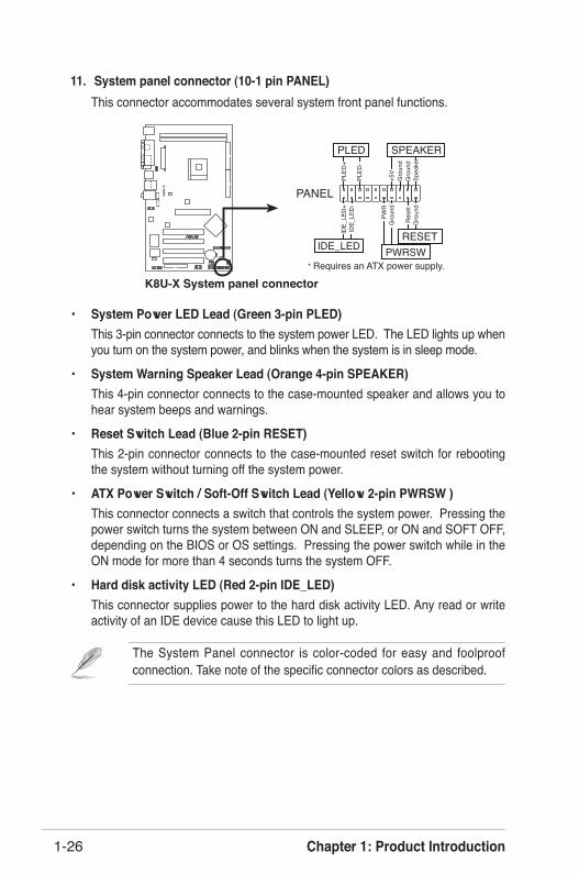
The System Panel connector is color-coded for easy and foolproof connection. Take note of the specific connector colors as described.
K8U
-X
®
K8U-X System panel connector* Requires an ATX power supply.
PLED
-
PWR
+5V
Spea
ker
PLED
Gro
und
RESET
Gro
und
Res
etG
roun
dG
roun
d
PLED
+ID
E_LE
D-
IDE_
LED
+
IDE_LED
SPEAKER
PWRSW
PANEL
11. System panel connector (10-1 pin PANEL)This connector accommodates several system front panel functions.
• System Power LED Lead (Green 3-pin PLED)This 3-pin connector connects to the system power LED. The LED lights up when you turn on the system power, and blinks when the system is in sleep mode.
• System Warning Speaker Lead (Orange 4-pin SPEAKER)This 4-pin connector connects to the case-mounted speaker and allows you to hear system beeps and warnings.
• Reset Switch Lead (Blue 2-pin RESET)This 2-pin connector connects to the case-mounted reset switch for rebooting the system without turning off the system power.
• ATX Power Switch / Soft-Off Switch Lead (Yellow 2-pin PWRSW )This connector connects a switch that controls the system power. Pressing the power switch turns the system between ON and SLEEP, or ON and SOFT OFF, depending on the BIOS or OS settings. Pressing the power switch while in the ON mode for more than 4 seconds turns the system OFF.
• Hard disk activity LED (Red 2-pin IDE_LED)This connector supplies power to the hard disk activity LED. Any read or write activity of an IDE device cause this LED to light up.
This chapter tells how to change system settings through the BIOS Setup menus. De ta i l ed desc r i p t i ons o f t he B IOS parameters are also provided.
BIOS Information
Chapter 2
Chapter 2: BIOS Setup2-2
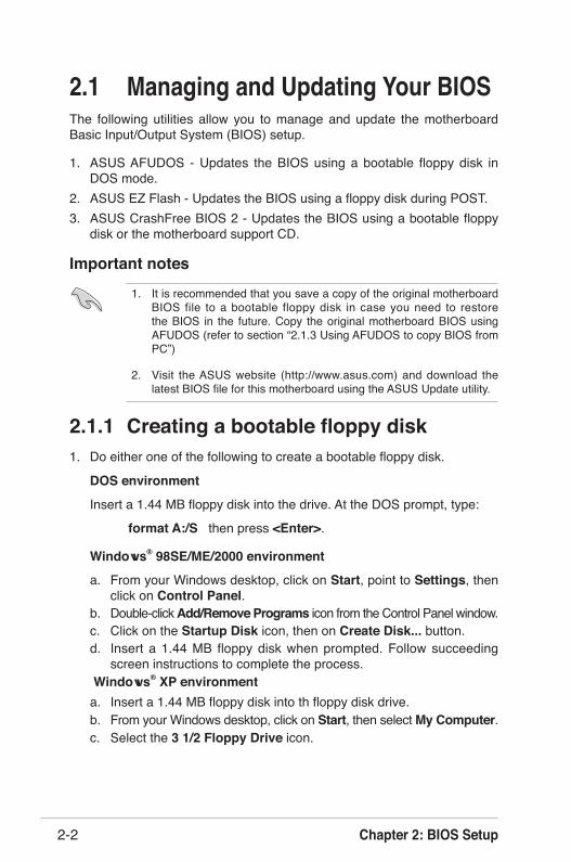
2.1 Managing and Updating Your BIOSThe following utilities allow you to manage and update the motherboard Basic Input/Output System (BIOS) setup.
1. ASUS AFUDOS - Updates the BIOS using a bootable floppy disk in DOS mode.
2. ASUS EZ Flash - Updates the BIOS using a floppy disk during POST. 3. ASUS CrashFree BIOS 2 - Updates the BIOS using a bootable floppy
disk or the motherboard support CD.
1. It is recommended that you save a copy of the original motherboard BIOS file to a bootable floppy disk in case you need to restore the BIOS in the future. Copy the original motherboard BIOS using AFUDOS (refer to section “2.1.3 Using AFUDOS to copy BIOS from PC”)
2. Visit the ASUS website (http://www.asus.com) and download the latest BIOS file for this motherboard using the ASUS Update utility.
Important notes
2.1.1 Creating a bootable floppy disk1. Do either one of the following to create a bootable floppy disk.
DOS environment
Insert a 1.44 MB floppy disk into the drive. At the DOS prompt, type:
format A:/S then press <Enter>.
Windows® 98SE/ME/2000 environment
a. From your Windows desktop, click on Start, point to Settings, then click on Control Panel.
b. Double-click Add/Remove Programs icon from the Control Panel window. c. Click on the Startup Disk icon, then on Create Disk... button.d. Insert a 1.44 MB floppy disk when prompted. Follow succeeding
screen instructions to complete the process. Windows® XP environmenta. Insert a 1.44 MB floppy disk into th floppy disk drive.b. From your Windows desktop, click on Start, then select My Computer.c. Select the 3 1/2 Floppy Drive icon.

ASUS K8U-X Motherboard 2-3
d. Click File from the menu, then select Format. A Format 3 1/2 Floppy Disk window appears.
e. Select Create a MS-DOS startup disk from the format ooptions field, thenn click Start.
2. Copy the original (or the latest) motherboard BIOS to the bootable floppy disk.
2.1.2 Using AFUDOS to update the BIOSUpdate the BIOS using the AFUDOS.EXE utility in DOS enviroment.
1. Visit the ASUS website (www.asus.com) to download the latest BIOS file for your motherboard. Save the BIOS file to a bootable floppy disk.
Write the BIOS file name on a piece of paper. You need to type the exact BIOS file name at the prompt.
2. Copy the AFUDOS.EXE utility from the support CD to the bootable floppy disk that contains the BIOS file.
3. Boot the system from the floppy disk.4. At the DOS prompt, type the command line:
afudos /i[filename]
where [filename] means the latest (or original) BIOS file that you copied to the bootable floppy disk.
5. Press <Enter>. The succeeding screen displays the status of the update process.
The BIOS information on the screen is for reference only. What you see on your screen may not be exactly the same as shown.
A:\>afudos /iK8U-X.ROM
AMI Firmware Update Utility - Version 1.10
Copyright (C) 2002 American Megatrends, Inc. All rights reserved.
Reading file ..... done
Erasing flash .... done
Writing flash .... 0x0008CC00 (9%)
DO NOT shutdown or reset the system while updating the BIOS! Doing so may cause system boot failure!

Chapter 2: BIOS Setup2-4
When the BIOS update process is complete, the utility returns to the DOS prompt
A:\>afudos /iK8U-X.ROM
AMI Firmware Update Utility - Version 1.10
Copyright (C) 2002 American Megatrends, Inc. All rights reserved.
Reading file ..... done
Erasing flash .... done
Writing flash .... 0x0008CC00 (9%)
Verifying flash .. done
A:\>
6. Reboot the system from the hard disk.
2.1.3 Using AFUDOS to copy BIOS from PCYou can use the AFUDOS.EXE utility to copy the current system BIOS to a floppy or hard disk and use it as a backup in case the system BIOS fails or gets corrupted.
1. At the DOS prompt, type the command line:
afudos /o[filename]
where [filename] string of not more than 8 alpha-numeric characters for the main filename and 3 alpha-numeric characters for the extension name.
The BIOS information on the screen is for reference only. What you see on your screen may not be exactly the same as shown..
Main filenameExtension name
A:\>afudos /oMYBIOS03.rom
AMI Firmware Update Utility - Version 1.10
Copyright (C) 2002 American Megatrends, Inc. All rights reserved.
Reading flash ..... 0x0008CC00 (9%)
2. Press <Enter>.

ASUS K8U-X Motherboard 2-5
2.1.4 Using ASUS EZ Flash to update the BIOSThe ASUS EZ Flash feature allows you to easily update the BIOS without having to go through the long process of booting from a diskette and using a DOS-based utility. The EZ Flash is built-in the BIOS firmware so it is accessible by simply pressing <Alt + F2> during the Power-On Self Tests (POST).
User recovery requested. Starting BIOS recovery...
Checking for floppy...
A:\>afudos /oMYBIOS03.rom
AMI Firmware Update Utility - Version 1.10
Copyright (C) 2002 American Megatrends, Inc. All rights reserved.
Reading flash ..... done
A:\>
3. The utility will copy the current system BIOS by default to the floppy disk. Make sure that the floppy disk has at least 600KB of free disk space and is not write-protected.
When the copy process is complete, the utility returns to the DOS prompt.
To update the BIOS using ASUS EZ Flash:
1. Visit the ASUS website (www.asus.com) to download the latest BIOS file for your motherboard and rename the downloaded file as K8U-X.ROM. Save the BIOS file to a floppy disk.
2. Reboot the system.3. To launch EZ Flash, press <Alt+F2> during POST to display the following.
• If there is no floppy disk in the drive, the error message “Floppy not found!” appears.
• If the correct BIOS file is not in the floppy disk, the error message “Floppy not found!” is displayed. Make sure to rename the downloaded BIOS file as “K8U-X.ROM”.

Chapter 2: BIOS Setup2-6
4. Insert the floppy disk that contains the BIOS file. If all the necessary files are found in the floppy disk, EZ Flash performs the BIOS update process and automatically reboots the system when done.
DO NOT shutdown or reset the system while updating the BIOS! Doing so may cause system boot failure!
User recovery requested. Starting BIOS recovery...
Checking for floppy...
Floppy found!
Reading file “K8U-X.ROM”. Completed.
Start flashing...
Flashed successfully. Rebooting.
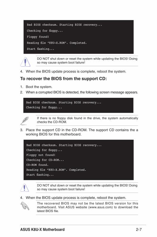
2.1.5 Recovering the BIOS with CrashFree BIOS 2The CrashFree BIOS 2 auto recovery tool allows you to restore BIOS from the motherboard support CD, or from a floppy disk that contains the BIOS file, in case the current BIOS on the motherboard fails or gets corrupted.
1. Prepare the support CD that came with the motherboard or a floppy disk that contains the motherboard BIOS before proceeding with the BIOS update process.
2. If you have saved a copy of the original motherboard BIOS to a bootable floppy disk, you may also use this disk to restore the BIOS. See section “2.1.1 Creating a bootable floppy disk.”
To recover the BIOS from a floppy disk:
1. Boot the system.2. When a corrupted BIOS is detected, the following screen message appears.
Bad BIOS checksum. Starting BIOS recovery...
Checking for floppy...
3. Insert a floppy disk that contains the original or the latest BIOS file for this motherboard. If all the necessary files are found in the floppy disk, the BIOS update process continues.
Make sure that the BIOS file in the floppy disk is renamed as “K8U-X.ROM”.
ASUS K8U-X Motherboard 2-7
DO NOT shut down or reset the system while updating the BIOS! Doing so may cause system boot failure!
DO NOT shut down or reset the system while updating the BIOS! Doing so may cause system boot failure!
If there is no floppy disk found in the drive, the system automatically checks the CD-ROM.
To recover the BIOS from the support CD:
1. Boot the system.2. When a corrupted BIOS is detected, the following screen message appears.
3. Place the support CD in the CD-ROM. The support CD contains the a working BIOS for this motherboard.
4. When the BIOS update process is complete, reboot the system.
Bad BIOS checksum. Starting BIOS recovery...
Checking for floppy...
Floppy found!
Reading file “K8U-X.ROM”. Completed.
Start flashing...
4. When the BIOS update process is complete, reboot the system.The recovered BIOS may not be the latest BIOS version for this motherboard. Visit ASUS website (www.asus.com) to download the latest BIOS file.
Bad BIOS checksum. Starting BIOS recovery...
Checking for floppy...
Bad BIOS checksum. Starting BIOS recovery...
Checking for floppy...
Floppy not found!
Checking for CD-ROM...
CD-ROM found.
Reading file “K8U-X.ROM”. Completed.
Start flashing...

Chapter 2: BIOS Setup2-8
2.2 BIOS Setup ProgramThis motherboard supports a programmable firmware chip that you can update using the provided utility described in section “2.1 Managing and updating your BIOS.”
Use the BIOS Setup program when you are installing a motherboard, reconfiguring your system, or prompted to “Run Setup”. This section explains how to configure your system using this utility.
Even if you are not prompted to use the Setup program, you may want to change the configuration of your computer in the future. For example, you may want to enable the security password feature or change the power management settings. This requires you to reconfigure your system using the BIOS Setup program so that the computer can recognize these changes and record them in the CMOS RAM of the firmware hub.
The firmware hub on the motherboard stores the Setup utility. When you start up the computer, the system provides you with the opportunity to run this program. Press <Del> during the Power-On Self Test (POST) to enter the Setup utility. Otherwise, POST continues with its test routines.
If you wish to enter Setup after POST, restart the system by pressing <Ctrl+Alt+Delete>, or by pressing the reset button on the system chassis. You can also restart by turning the system off and then back on. Do this last option only if the first two failed.
The Setup program is designed to make it as easy to use as possible. It is a menu-driven program, which means you can scroll through the various sub-menus and make your selections from the available options using the navigation keys.
The default BIOS settings for this motherboard apply for most conditions to ensure optimum performance. If the system becomes unstable after changing any BIOS settings, load the default settings to ensure system compatibility and stability. Select the Load Default Settings item under the Exit Menu. See section “2.7 Exit Menu.”
The BIOS setup screens shown in this chapter are for reference purposes only, and may not exactly match what you see on your screen.
Visit the ASUS website (www.asus.com) to download the latest product and BIOS information.
ASUS K8U-X Motherboard 2-9
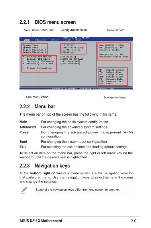
2.2.1 BIOS menu screen
2.2.2 Menu barThe menu bar on top of the screen has the following main items:
Main For changing the basic system configurationAdvanced For changing the advanced system settingsPower For changing the advanced power management (APM)
configurationBoot For changing the system boot configurationExit For selecting the exit options and loading default settings
To select an item on the menu bar, press the right or left arrow key on the keyboard until the desired item is highlighted.
Some of the navigation keys differ from one screen to another.
2.2.3 Navigation keysAt the bottom right corner of a menu screen are the navigation keys for that particular menu. Use the navigation keys to select items in the menu and change the settings.
System Time [11:10:19]System Date [Thu 03/10/2005]Legacy Diskette A [1.44M, 3.5 in]Legacy Diskette B [Disabled]
Primary IDE Master :[ST320413A] Primary IDE Slave :[ASUS CD-S400/A] Secondary IDE Master :[Not Detected] Secondary IDE Slave :[Not Detected]
System Information
Use [ENTER], [TAB]or [SHIFT-TAB] toselect a field.
Use [+] or [-] toconfigure system time.
Select Screen Select Item+- Change FieldTab Select FieldF1 General HelpF10 Save and ExitESC Exit
Navigation keys
General helpMenu bar
Sub-menu items
Configuration fieldsMenu items

Chapter 2: BIOS Setup2-10
2.2.6 Configuration fieldsThese fields show the values for the menu items. If an item is user- configurable, you may change the value of the field opposite the item. You can not select an item that is not user-configurable. A configurable field is enclosed in brackets, and is highlighted when selected. To change the value of a field, select it then press <Enter> to display a list of options. Refer to “2.2.7 Pop-up window.”
2.2.7 Pop-up windowSelect a menu item then press Enter to display a pop-up window with the configuration options for that item.
2.2.8 Scroll barA scroll bar appears on the right side of a menu screen when there are items that do not fit on the screen. Press Up/Down arrow keys or PageUp/PageDown keys to display the other items on the screen.
2.2.9 General helpAt the top right corner of the menu screen is a brief description of the selected item.
Select Screen Select Item+- Change OptionF1 General HelpF10 Save and ExitESC Exit
Advanced Chipset settings
WARNING: Setting wrong values in the sections below may cause system to malfunction.
Configure DRAM Timing by SPD [Enabled]Memory Acceleration Mode [Auto]DRAM Idle Timer [Auto]DRAm Refresh Rate [Auto]
Graphic Adapter Priority [AGP/PCI]Graphics Aperture Size [ 64 MB]Spread Spectrum [Enabled]
ICH Delayed Transaction [Enabled]
MPS Revision [1.4]
2.2.4 Menu itemsThe highlighted item on the menu bar displays the specific items for that menu. For example, selecting Main shows the Main menu items.
The other items (Advanced, Power, Boot, and Exit) on the menu bar have their respective menu items.
2.2.5 Sub-menu itemsAn item with a sub-menu on any menu screen is distinguished by a solid triangle before the item. To display the sub-menu, select the item and press <Enter>.
Main menu items
System Time [11:10:19]System Date [Thu 03/10/2005]Legacy Diskette A [1.44M, 3.5 in]Legacy Diskette B [Disabled]
Primary IDE Master :[ST320413A] Primary IDE Slave :[ASUS CD-S400/A] Secondary IDE Master :[Not Detected] Secondary IDE Slave :[Not Detected]
System Information
Use [ENTER], [TAB]or [SHIFT-TAB] toselect a field.
Use [+] or [-] toconfigure system time.
Select Screen Select Item+- Change FieldTab Select FieldF1 General HelpF10 Save and ExitESC Exit
Pop-up window Scroll bar

ASUS K8U-X Motherboard 2-11
2.3 Main MenuWhen you enter the BIOS Setup program, the Main menu screen appears giving you an overview of the basic system information.
2.3.1 System Time [xx:xx:xxxx]Allows you to set the system time.
2.3.2 System Date [Day xx/xx/xxxx]Allows you to set the system date.
2.3.3 Legacy Diskette A, B [1.44M, 3.5 in.]Sets the type of floppy drive installed. Configuration options: [Disabled] [360K, 5.25 in.] [1.2M , 5.25 in.] [720K, 3.5 in.] [1.44M, 3.5 in.] [2.88M, 3.5 in.]
Refer to section “2.2.1 BIOS menu screen” for information on the menu screen items and how to navigate through them.
System Time [11:51:19] Use [ENTER], [TAB]System Date [Thu 08/05/2003] or [SHIFT-TAB] to Legacy Diskette A [1.44M, 3.5 in] select a field.Legacy Diskette B [Disabled]
Primary IDE Master : [ST320413A] Use [+] or [-] to Primary IDE Slave : [ASUS CD-S340] configure system time. Secondary IDE Master : [Not Detected] Secondary IDE Slave : [Not Detected] System Information
Chapter 2: BIOS Setup2-12
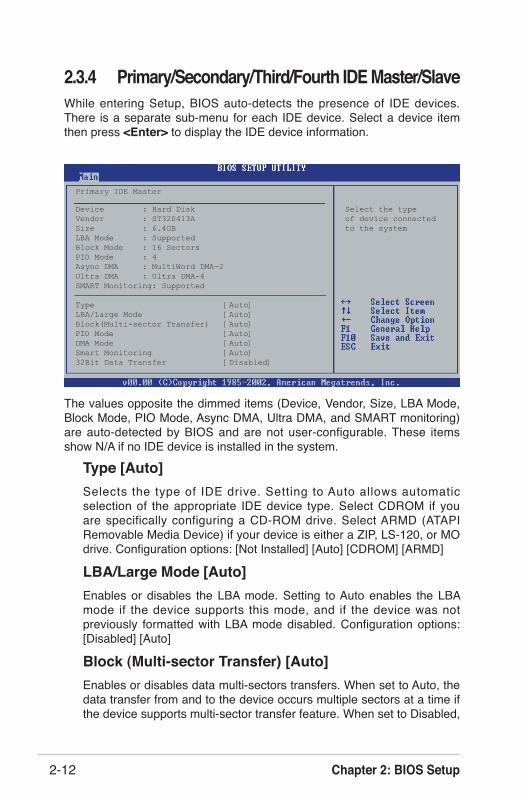
2.3.4 Primary/Secondary/Third/Fourth IDE Master/SlaveWhile entering Setup, BIOS auto-detects the presence of IDE devices. There is a separate sub-menu for each IDE device. Select a device item then press <Enter> to display the IDE device information.
The values opposite the dimmed items (Device, Vendor, Size, LBA Mode, Block Mode, PIO Mode, Async DMA, Ultra DMA, and SMART monitoring) are auto-detected by BIOS and are not user-configurable. These items show N/A if no IDE device is installed in the system.
Type [Auto]Selects the type of IDE drive. Setting to Auto allows automatic selection of the appropriate IDE device type. Select CDROM if you are specifically configuring a CD-ROM drive. Select ARMD (ATAPI Removable Media Device) if your device is either a ZIP, LS-120, or MO drive. Configuration options: [Not Installed] [Auto] [CDROM] [ARMD]
LBA/Large Mode [Auto]Enables or disables the LBA mode. Setting to Auto enables the LBA mode if the device supports this mode, and if the device was not previously formatted with LBA mode disabled. Configuration options: [Disabled] [Auto]
Block (Multi-sector Transfer) [Auto]Enables or disables data multi-sectors transfers. When set to Auto, the data transfer from and to the device occurs multiple sectors at a time if the device supports multi-sector transfer feature. When set to Disabled,
Primary IDE Master
Device : Hard Disk Select the typeVendor : ST320413A of device connectedSize : 6.4GB to the systemLBA Mode : SupportedBlock Mode : 16 SectorsPIO Mode : 4Async DMA : MultiWord DMA-2Ultra DMA : Ultra DMA-4SMART Monitoring: Supported
Type [Auto]LBA/Large Mode [Auto]Block(Multi-sector Transfer) [Auto]PIO Mode [Auto]DMA Mode [Auto]Smart Monitoring [Auto]32Bit Data Transfer [Disabled]

ASUS K8U-X Motherboard 2-13
2.3.5 System InformationThis menu gives you an overview of the general system specifications. The items in this menu are auto-detected by BIOS.
AMI BIOSDisplays the auto-detected BIOS information.
ProcessorDisplays the auto-detected CPU specification.
System MemoryDisplays the auto-detected system memory.
the data transfer from and to the device occurs one sector at a time.Configuration options: [Disabled] [Auto]
PIO Mode [Auto]Selects the PIO mode. Configuration options: [Auto] [0] [1] [2] [3] [4].
DMA Mode [Auto]Selects the DMA mode. Configuration options: [Auto] [SWDMA0] [SWDMA1] [SWDMA2] [MWDMA0] [MWDMA1] [MWDMA2] [UDMA0] [UDMA1] [UDMA2] [UDMA3] [UDMA4] [UDMA5] [UDMA6].
SMART Monitoring [Auto]Sets the Smart Monitoring, Analysis, and Reporting Technology. Configuration options: [Auto] [Disabled] [Enabled].
32Bit Data Transfer [Disabled]Enables or disables 32-bit data transfer. Configuration options: [Disabled] [Enabled]
AMI BIOSVersion : 0122Build Date : 02/23/05
ProcessorType : AMD Athlon(tm) 64 Processor 3200+Speed : 2010MHzCount : 1
System MemorySize : 256MB
Chapter 2: BIOS Setup2-14
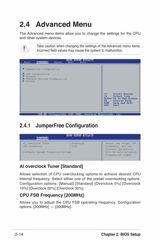
Take caution when changing the settings of the Advanced menu items. Incorrect field values may cause the system to malfunction.
2.4 Advanced MenuThe Advanced menu items allow you to change the settings for the CPU and other system devices.
JumperFree Configuration
CPU ConfigurationChipsetOnboard Devices ConfigurationPCIPnP
2.4.1 JumperFree Configuration
AI Overclock Tuner [Standard] Select the target CPUCPU Frequency [200] frequency, and the relevant parameters Configure System Frequency/Voltage will be auto-adjusted. Frequencies higher
AI overclock Tuner [Standard]Allows selection of CPU overclocking options to achieve desired CPU internal frequency. Select either one of the preset overclocking options. Configuration options: [Manual] [Standard] [Overclock 5%] [Overclock 10%] [Overclock 20%] [Overclock 30%].
CPU FSB Frequency [200MHz]Allows you to adjust the CPU FSB operating frequency. Configuration options: [200MHz] ~ [300MHz].
ASUS K8U-X Motherboard 2-15
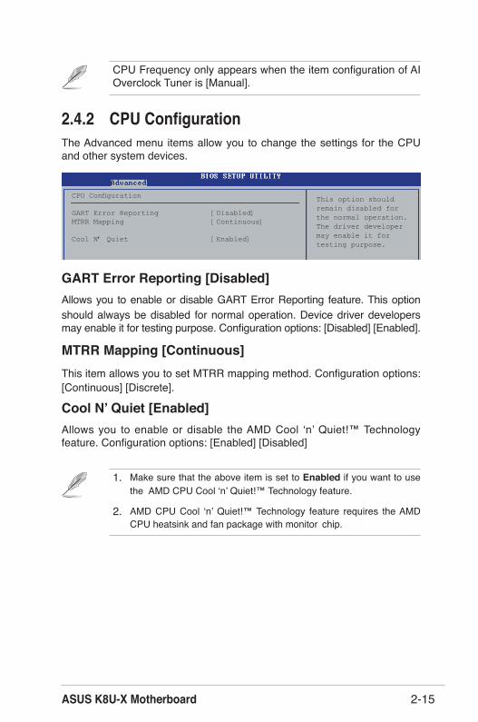
2.4.2 CPU ConfigurationThe Advanced menu items allow you to change the settings for the CPU and other system devices.
This option should remain disabled for the normal operation. The driver developer may enable it for testing purpose.
1. Make sure that the above item is set to Enabled if you want to use the AMD CPU Cool ʻnʼ Quiet!™ Technology feature.
2. AMD CPU Cool ʻnʼ Quiet!™ Technology feature requires the AMD CPU heatsink and fan package with monitor chip.
CPU Configuration GART Error Reporting [Disabled]MTRR Mapping [Continuous]
Cool N’ Quiet [Enabled]
GART Error Reporting [Disabled]Allows you to enable or disable GART Error Reporting feature. This option should always be disabled for normal operation. Device driver developers may enable it for testing purpose. Configuration options: [Disabled] [Enabled].
MTRR Mapping [Continuous]This item allows you to set MTRR mapping method. Configuration options: [Continuous] [Discrete].
Cool N ̓Quiet [Enabled]Allows you to enable or disable the AMD Cool ʻnʼ Quiet!™ Technology feature. Configuration options: [Enabled] [Disabled]
CPU Frequency only appears when the item configuration of AI Overclock Tuner is [Manual].

Chapter 2: BIOS Setup2-16
NorthBridge Configuration
2.4.3 ChipsetThe Chipset menu items allow you to change the advanced chipset settings. Select an item then press <Enter> to display the sub-menu.
Chipset Settings NorthBridge Configuration HyperTransport Configuration SouthBridge Configuration AGP Configuration Spread Spectrum [Enable] MPS Revision [1.1]
NorthBridge Configuration
Memory Configuration
Memory CLK : 200MHz CAS Latency : 2.5 TRCD : 3 CLK TRAS : 8 CLK TRP : 3 CLK
ASUS K8U-X Motherboard 2-17
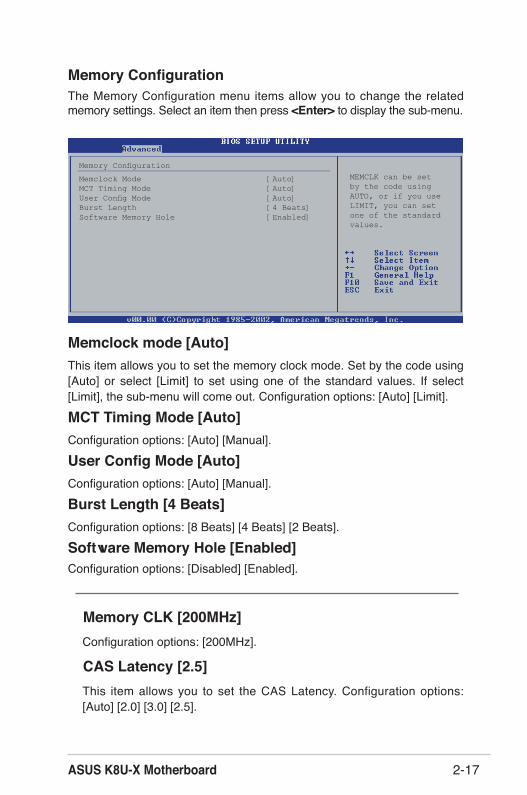
Memory ConfigurationThe Memory Configuration menu items allow you to change the related memory settings. Select an item then press <Enter> to display the sub-menu.
MEMCLK can be set by the code usingAUTO, or if you useLIMIT, you can setone of the standardvalues.
Memory Configuration
Memclock Mode [Auto]MCT Timing Mode [Auto]User Config Mode [Auto]Burst Length [4 Beats]Software Memory Hole [Enabled]
Memclock mode [Auto]This item allows you to set the memory clock mode. Set by the code using [Auto] or select [Limit] to set using one of the standard values. If select [Limit], the sub-menu will come out. Configuration options: [Auto] [Limit].
MCT Timing Mode [Auto]Configuration options: [Auto] [Manual].
User Config Mode [Auto]Configuration options: [Auto] [Manual].
Burst Length [4 Beats]Configuration options: [8 Beats] [4 Beats] [2 Beats].
Software Memory Hole [Enabled]Configuration options: [Disabled] [Enabled].
Memory CLK [200MHz] Configuration options: [200MHz].
CAS Latency [2.5]This item allows you to set the CAS Latency. Configuration options: [Auto] [2.0] [3.0] [2.5].
Chapter 2: BIOS Setup2-18
TRCD [3 CLK]This item displays the TRCD clock setting. Configuration options: [Auto] [2 CLK] [3 CLK] [4 CLK] [5 CLK] [6 CLK].
TRAS [8 CLK]This item displays the TRAS clock setting. Configuration options: [Auto] [5 CLK] [6 CLK] [7 CLK] [8 CLK] [9 CLK] [10 CLK] [11 CLK] [12 CLK] [13 CLK] [14 CLK] [15 CLK].
TRP [3 CLK]This item displays the TRCD clock setting. Configuration options: [Auto] [2 CLK] [3 CLK] [4 CLK] [5 CLK] [6 CLK].
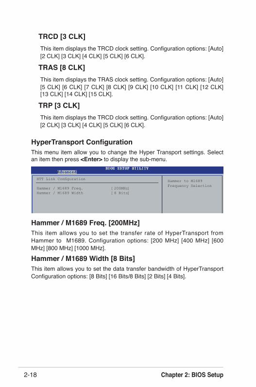
HyperTransport ConfigurationThis menu item allow you to change the Hyper Transport settings. Select an item then press <Enter> to display the sub-menu.
Hammer / M1689 Freq. [200MHz]This item allows you to set the transfer rate of HyperTransport from Hammer to M1689. Configuration options: [200 MHz] [400 MHz] [600 MHz] [800 MHz] [1000 MHz].
Hammer / M1689 Width [8 Bits]This item allows you to set the data transfer bandwidth of HyperTransport Configuration options: [8 Bits] [16 Bits/8 Bits] [2 Bits] [4 Bits].
Hammer to M1689 Frequency Selection
HTT Link Configuration Hammer / M1689 Freq. [200MHz]Hammer / M1689 Width [8 Bits]
ASUS K8U-X Motherboard 2-19
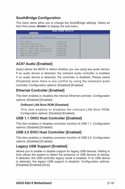
SouthBridge ConfigurationThe menu items allow you to change the SouthBridge settings. Select an item then press <Enter> to display the sub-menu.
SouthBridge Chipset Configuration AC97 Audio [Enabled]Ethernet Controller [Enabled] Onboard LAN Boot ROM [Disabled]USB 1.1 OHCI Host Controller [Enabled]USB 2.0 EHCI Host Controller [Enabled]Legacy USB Support [Enabled]SATA Controller [Enabled]
AC97 Audio [Enabled][Auto] allows the BIOS to detect whether you are using any audio device. If an audio device is detected, the onboard audio controller is enabled; if no audio device is detected, the controller is disabled. Please select [Disabled] when there is any conflict by using the onbaoard audio controller. Configuration options: [Disabled] [Enabled].
Ethernet Controller [Enabled]This item enables or disables the internal Ethernet controler. Configuration options: [Disabled] [Enabled].
OnBoard LAN Boot ROM [Disabled]This i tem enables or d isables the onboard LAN Boot ROM. Configuration options: [Disabled] [Enabled].
USB 1.1 OHCI Host Controller [Enabled]This item enables or disables connector function of USB 1.1. Configuration options: [Disabled] [Enabled].
USB 2.0 EHCI Host Controller [Enabled]This item enables or disables connector function of USB 2.0. Configuration options: [Disabled] [Enabled].
Legacy USB Support [Enabled]Allows you to enable or disable support for legacy USB devices. Setting to Auto allows the system to detect the presence of USB devices at startup. If detected, the USB controller legacy mode is enabled. If no USB device is detected, the legacy USB support is disabled. Configuration options: [Disabled] [Enabled] [Auto].

Chapter 2: BIOS Setup2-20
AGP Configuration
Primary Graphics Adapter [AGP]Switches the PCI Bus scanning order while searching for a video card. This allows you to select the type of Primary VGA in case of multiple video controllers. Configuration options: [PCI] [AGP].
AGP Data Transfer Rate [1x/2x/4x/8x]This motherboard supports the AGP 8X interface that transfers video data at 2.12GB/s. The default and configuration options vary depending on the speed of AGP card you installed. If you installed an AGP 8X graphics card, the configuration options are as follows: [8X] [4X]. Even if you installed an AGP 4X graphics card, you can keep [AGP 8X] as your configuration. In that case, even if you installed AGP 8X graphic card, it only can provide 1.06GB/s as its transfer rate. Configuration options: [1x/2x/4x/8x] [1x/2x/4x].
Aperture Size [256MB]This item sets the Aperture size for the AGP Video controller. Configuration options: [32MB] [64MB] [128MB] [256MB].
FW Enable [Enabled]This item enables or disables the AGP FW function. Configuration options: [Enabled] [Disabled].
AGP Chipset Configuration
Primary Graphics Adapter [AGP]AGP Data Transfer Rate [1x/2x/4x/8x]Aperture Size [256MB]FW Enable [Enabled]
SATA Controller [Enabled]This item enables or disables Serial ATA function. Configuration options: [Disabled] [Enabled],
Spread Spectrum [Enable]This item enables or disables the Spread Spectrum function. Configuration options: [Disabled] [Enabled].
MPS Revision [1.1]Sets the MPS revision value. Configuration options: [1.1] [1.4].
ASUS K8U-X Motherboard 2-21
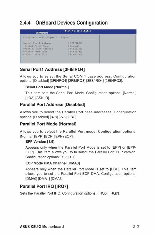
2.4.4 OnBoard Devices Configuration
Configure ITE8712 Super IO Chipset
Serial Port1 Address [3F8/IRQ4] Serial Port1 Mode [Normal]Parallel Port Address [Disabled]OnBoard Game Port [Disabled]OnBoard MIDI Port [Disabled]
Serial Port1 Address [3F8/IRQ4]Allows you to select the Serial COM 1 base address. Configuration options: [Disabled] [3F8/IRQ4] [2F8/IRQ3] [3E8/IRQ4] [2E8/IRQ3].
Serial Port Mode [Normal]This item sets the Serial Port Mode. Configuration options: [Normal] [IrDA] [ASK IR].
Parallel Port Address [Disabled]Allows you to select the Parallel Port base addresses. Configuration options: [Disabled] [378] [278] [3BC].
Parallel Port Mode [Normal]Allows you to select the Parallel Port mode. Configuration options: [Normal] [EPP] [ECP] [EPP+ECP].
EPP Version [1.9]Appears only when the Parallel Port Mode is set to [EPP] or [EPP-ECP]. This item allows you to to select the Parallel Port EPP version. Configuration options: [1.9] [1.7]ECP Mode DMA Channel [DMA3]Appears only when the Parallel Port Mode is set to [ECP]. This item allows you to set the Parallel Port ECP DMA. Configuration options: [DMA0] [DMA1] [DMA3]
Parallel Port IRQ [IRQ7]Sets the Parallel Port IRQ. Configuration options: [IRQ5] [IRQ7].

Chapter 2: BIOS Setup2-22
Take caution when changing the settings of the PCI PnP menu items. Incorrect field values may cause the system to malfunction.
Onboard Game Port [Disabled] Enables or disables the onboard GAME port. C o n f i g u r a t i o n o p t i o n s : [Disabled] [Enabled].
Onboard MIDI Port [Disabled] Enables or disables the onboard MIDI port. Configuration options: [Disabled] [300] [330].
2.4.5 PCI PnPThe PCI PnP menu items allow you to change the advanced settings for PCI/PnP devices. The menu includes setting IRQ and DMA channel resources for either PCI/PnP or legacy ISA devices, and setting the memory size block for legacy ISA devices.
Plug and Play O/S [No]When set to [No], BIOS configures all the devices in the system. When set to [Yes] and if you installed a Plug & Play operating system, the operating system configures the Plug & Play devices not required for boot. Configuration options: [No] [Yes].
PCI Latency Timer [64]Allows you to select the value in units of PCI clocks for the PCI device latency timer register. Configuration options: [32] [64] [96] [128] [160] [192] [224] [248].
Advanced PCI/PnP Settings NO: Lets the BIOS configure all the WARNING: Setting wrong values in below sections devices in the system. may cause system to malfunction. YES: Lets the operating systemPlug And Play O/S [No] configure Plug andPCI Lantency Timer [64] Play (PnP) devices notAllocate IRQ to PCI VGA [Yes] required for boot ifPalette Snooping [Disabled] your system has a Plug and Play operating system.
IRQ-3 assigned to [PCI Device] IRQ-4 assigned to [PCI Device] IRQ-5 assigned to [PCI Device]IRQ-7 assigned to [PCI Device]IRQ-9 assigned to [PCI Device]IRQ-10 assigned to [PCI Device]IRQ-11 assigned to [PCI Device]IRQ-14 assigned to [PCI Device]IRQ-15 assigned to [PCI Device]
ASUS K8U-X Motherboard 2-23
Allocate IRQ to PCI VGA [Yes]When set to [Yes], BIOS assigns an IRQ to PCI VGA card if the card requests for an IRQ. When set to [No], BIOS does not assign an IRQ to the PCI VGA card even if requested. Configuration options: [Yes] [No]
Palette Snooping [Disabled]When set to [Enabled], the pallete snooping feature informs the PCI devices that an ISA graphics device is installed in the system so that the latter can function correctly. Setting to [Disabled] deactivates this feature. Configuration options: [Disabled] [Enabled].
IRQ-xx assigned to [PCI Device]When set to [Available], the specific IRQ is free for use of PCI/PnP devices. When set to [Reserved], the IRQ is reserved for legacy ISA devices. Configuration options: [PCI Device] [Reserved].
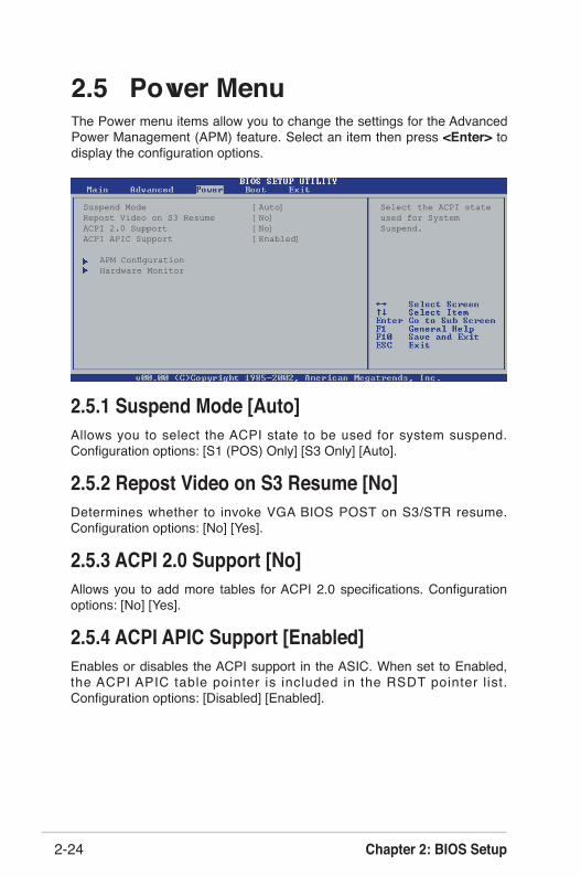
Chapter 2: BIOS Setup2-24
Suspend Mode [Auto] Select the ACPI stateRepost Video on S3 Resume [No] used for SystemACPI 2.0 Support [No] Suspend.ACPI APIC Support [Enabled]
APM Configuration Hardware Monitor
2.5 Power MenuThe Power menu items allow you to change the settings for the Advanced Power Management (APM) feature. Select an item then press <Enter> to display the configuration options.
2.5.1 Suspend Mode [Auto]Allows you to select the ACPI state to be used for system suspend. Configuration options: [S1 (POS) Only] [S3 Only] [Auto].
2.5.2 Repost Video on S3 Resume [No]Determines whether to invoke VGA BIOS POST on S3/STR resume. Configuration options: [No] [Yes].
2.5.3 ACPI 2.0 Support [No]Allows you to add more tables for ACPI 2.0 specifications. Configuration options: [No] [Yes].
2.5.4 ACPI APIC Support [Enabled]Enables or disables the ACPI support in the ASIC. When set to Enabled, the ACPI APIC table pointer is included in the RSDT pointer l ist. Configuration options: [Disabled] [Enabled].
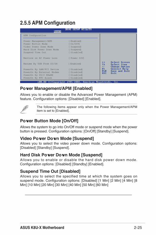
ASUS K8U-X Motherboard 2-25
2.5.5 APM Configuration
Power Management/APM [Enabled]Allows you to enable or disable the Advanced Power Management (APM) feature. Configuration options: [Disabled] [Enabled].
Power Button Mode [On/Off]Allows the system to go into On/Off mode or suspend mode when the power button is pressed. Configuration options: [On/Off] [Standby] [Suspend].
Video Power Down Mode [Suspend]Allows you to select the video power down mode. Configuration options: [Disabled] [Standby] [Suspend].
Hard Disk Power Down Mode [Suspend]Allows you to enable or disable the hard disk power down mode. Configuration options: [Disabled] [Standby] [Enabled].
Suspend Time Out [Disabled]Allows you to select the specified time at which the system goes on suspend mode. Configuration options: [Disabled] [1 Min] [2 Min] [4 Min] [8 Min] [10 Min] [20 Min] [30 Min] [40 Min] [50 Min] [60 Min]
The following items appear only when the Power Management/APM item is set to [Enabled].
APM Configuration
Power Management/APM [Enabled]Power Button Mode [On/Off]Video Power Down Mode [Suspend]Hard Disk Power Down Mode [Suspend]Suspend Time Out [Disabled]
Restore on AC Power Loss [Power Off]
Resume By USB From S3/S4 [Enabled]
PowerOn By LAN/PCI Device [Disabled]PowerOn By External Modem [Disabled]PowerOn By PS/2 KB&MS [Disabled]PowerOn By RTC Alarm [Disabled]

Chapter 2: BIOS Setup2-26
PowerOn By PS/2 KB&MS [Disabled]Allows you to enable or disable the keyboard and mouse wake-up feature. This feature requires an ATX power supply that provides at least 1A on the +5VSB lead. Configuration options: [Disabled] [Enabled].
Power On By RTC Alarm [Disabled]Allows you to enable or disable RTC to generate a wake event. When this item is set to Enabled, the items RTC Alarm Date, RTC Alarm Hour, RTC Alarm Minute, and RTC Alarm Second appear with set values. Configuration options: [Disabled] [Enabled].
The computer cannot receive or transmit data until the computer and applications are fully running. Thus, connection cannot be made on the first try. Turning an external modem off and then back on while the computer is off causes an initialization string that turns the system power on.
Restore on AC Power Loss [Power Off]When set to Power Off, the system goes into off state after an AC power loss. When set to Power On, the system goes on after an AC power loss. When set to Last State, the system goes into either off or on state whatever the system state before the AC power loss. Configuration options: [Power Off] [Power On] [Last State].
Resume By USB From S3/S4 [Enabled]Allows you to enable or disable USB for waking-up S3 or S4 mode. Configuration options: [Disabled] [Enabled].
PowerOn By LAN/PCI Device [Disabled]Allows you to enable or disable power on PCI and LAN device feature. This feature requires an ATX power supply that provides at least 1A on the +5VSB lead. Configuration options: [Disabled] [Enabled]
PowerOn By External Modem [Disabled]Allows either settings of [Enabled] or [Disabled] for powering up the computer when the external modem receives a call while the computer is in Soft-off mode. Configuration options: [Disabled] [Enabled],

ASUS K8U-X Motherboard 2-27
2.5.6 Hardware Monitor
MB Temperature [xxxC/xxxF]CPU Temperature [xxxC/xxxF]The onboard hardware monitor automatically detects and displays the motherboard, CPU and power temperatures. Select Disabled if you do not wish to display the detected temperatures.
CPU Fan Speed [xxxxRPM] or [N/A]Chassis Fan Speed [xxxxRPM] or [N/A]The onboard hardware monitor automatically detects and displays the CPU and chassis fan speeds in rotations per minute (RPM). If any of the fans is not connected to the motherboard, the specific field shows N/A. Configuration options: [xxxC/xxxF] [ignored].
VCORE Voltage, +3.3V Voltage, +5V Voltage, +12V Voltage The onboard hardware monitor automatically detects the voltage output through the onboard voltage regulators.
If any of the monitored items is out of range, the following error message appears: “Hardware Monitor found an error. Enter Power setup menu for details”. You will then be prompted to “Press F1 to continue or DEL to enter SETUP”.
CPU TemperatureMB Temperature [35ºC/95ºF]CPU Temperature [40ªC/104ºF]
CPU Fan Speed [5152RPM]Chassis Fan Speed [N/A]
VCORE Voltage [ 1.504V]3.3V Voltage [ 3.360V]5V Voltage [ 5.160V]12V Voltage [11.328V]

Chapter 2: BIOS Setup2-28
Boot Settings Specifies the Boot Device Priority Boot Device Priority sequence. Boot Settings Configuration Security
Boot Device Priority Specifies the boot sequence from the1st Boot Device [1st FLOPPY DRIVE] available devices.2nd Boot Device [PM-ST320413A] 3rd Boot Device [SM-ASUS CD-S360] A device enclosed in parenthesis has been disabled in the corresponding type menu.
1st˜xxth Boot Device [1st Floopy Drive]This item can let user choose the boot device and it specifies the boot device priority sequence from the available devices. 1st, 2nd, 3rd refer to the sequence of boot device. The names of device items that appear on the screen depend on the devices installed in the system. Configuration options: [xxxxx Drive] [Disabled].
2.6.1 Boot Device Priority
2.6 Boot Menu The Boot menu items allow you to change the system boot options. Select an item then press <Enter> to display the sub-menu.
2.6.2 Hard Disk Drives
1st˜xxth Drive These items specify the hard disk priority sequence from the available hard disk drives. The number of hard disk drive items that appear on the screen
Hard Disk Drives
1st Drive [PM-ST320413A]2nd Drive [xxxxxx Drive]
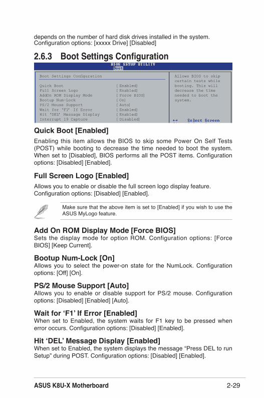
ASUS K8U-X Motherboard 2-29
Make sure that the above item is set to [Enabled] if you wish to use the ASUS MyLogo feature.
depends on the number of hard disk drives installed in the system. Configuration options: [xxxxx Drive] [Disabled]
2.6.3 Boot Settings Configuration
Quick Boot [Enabled]Enabling this item allows the BIOS to skip some Power On Self Tests (POST) while booting to decrease the time needed to boot the system. When set to [Disabled], BIOS performs all the POST items. Configuration options: [Disabled] [Enabled].
Full Screen Logo [Enabled]Allows you to enable or disable the full screen logo display feature. Configuration options: [Disabled] [Enabled].
Add On ROM Display Mode [Force BIOS]Sets the display mode for option ROM. Configuration options: [Force BIOS] [Keep Current].
Bootup Num-Lock [On]Allows you to select the power-on state for the NumLock. Configuration options: [Off] [On].
PS/2 Mouse Support [Auto]Allows you to enable or disable support for PS/2 mouse. Configuration options: [Disabled] [Enabled] [Auto].
Wait for ʻF1 ̓If Error [Enabled]When set to Enabled, the system waits for F1 key to be pressed when error occurs. Configuration options: [Disabled] [Enabled].
Hit ʻDEL ̓Message Display [Enabled]When set to Enabled, the system displays the message “Press DEL to run Setup” during POST. Configuration options: [Disabled] [Enabled].
Boot Settings Configuration Allows BIOS to skip certain tests while Quick Boot [Enabled] booting. This willFull Screen Logo [Enabled] decrease the timeAddOn ROM Display Mode [Force BIOS] needed to boot theBootup Num-Lock [On] system.PS/2 Mouse Support [Auto]Wait for ‘F1’ If Error [Enabled]Hit ‘DEL’ Message Display [Enabled]Interrupt 19 Capture [Disabled]

Chapter 2: BIOS Setup2-30
After you have set a supervisor password, the other items appear to allow you to change other security settings.
2.6.4 SecurityThe Security menu items allow you to change the system security settings. Select an item then press <Enter> to display the configuration options.
Change Supervisor PasswordSelect this item to set or change the supervisor password. The Supervisor Password item on top of the screen shows the default Not Installed. After you have set a password, this item shows Installed.
To set a Supervisor Password:
1. Select the Change Supervisor Password item and press <Enter>.2. From the password box, type a password combination of at least six
(6) letters and/or numbers, then press <Enter>.3. Confirm the password when prompted. The message “Password
Installed” appears after you have successfully set your password.The Supervisor Password item now shows Installed.
To change the supervisor password, follow the same steps as in setting a user password.
To clear the supervisor password, select the Change Supervisor Password then press <Enter>. The message “Password Uninstalled” appears.
Security Settings <Enter> to change password.Supervisor Password : Not Installed <Enter> again to User Password : Not Installed disable password.
Change Supervisor PasswordChange User PasswordClear User Password
Password Check [Setup]
If you forget your BIOS password, you can clear clear it by erasing the CMOS Real Time Clock (RTC) RAM. See section “1.9 Jumpers” for information on how to erase the RTC RAM.
Interrupt 19 Capture [Disabled]When set to [Enabled], this function allows the option ROMs to trap Interrupt 19. Configuration options: [Disabled] [Enabled].
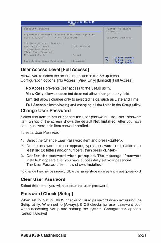
ASUS K8U-X Motherboard 2-31
User Access Level [Full Access]Allows you to select the access restriction to the Setup items. Configuration options: [No Access] [View Only] [Limited] [Full Access].
No Access prevents user access to the Setup utility. View Only allows access but does not allow change to any field.Limited allows change only to selected fields, such as Date and Time.Full Access allows viewing and changing all the fields in the Setup utility.
Change User PasswordSelect this item to set or change the user password. The User Password item on top of the screen shows the default Not Installed. After you have set a password, this item shows Installed.
To set a User Password:
1. Select the Change User Password item and press <Enter>.2. On the password box that appears, type a password combination of at
least six (6) letters and/or numbers, then press <Enter>.3. Confirm the password when prompted. The message “Password
Installed” appears after you have successfully set your password.The User Password item now shows Installed.
To change the user password, follow the same steps as in setting a user password.
Clear User PasswordSelect this item if you wish to clear the user password.
Password Check [Setup]When set to [Setup], BIOS checks for user password when accessing the Setup utility. When set to [Always], BIOS checks for user password both when accessing Setup and booting the system. Configuration options: [Setup] [Always]
Security Settings <Enter> to change password.Supervisor Password : Installed <Enter> again to User Password : Not Installed disabled password.
Change Supervisor PasswordUser Access Level [Full Access]Change User PasswordClear User PasswordPassword Check [Setup]
Boot Sector Virus Protection [Disabled]
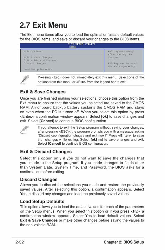
Chapter 2: BIOS Setup2-32
Exit & Discard ChangesSelect this option only if you do not want to save the changes that you made to the Setup program. If you made changes to fields other than System Date, System Time, and Password, the BIOS asks for a confirmation before exiting.
Discard ChangesAllows you to discard the selections you made and restore the previously saved values. After selecting this option, a confirmation appears. Select Yes to discard any changes and load the previously saved values.
Load Setup Defaults This option allows you to load the default values for each of the parameters on the Setup menus. When you select this option or if you press <F5>, a confirmation window appears. Select Yes to load default values. Select Exit & Save Changes or make other changes before saving the values to the non-volatile RAM.
Exit Options Exit system setup after saving theExit & Save Changes changes.Exit & Discard ChangesDiscard Changes F10 key can be used for this operation.Load Setup Defaults
2.7 Exit MenuThe Exit menu items allow you to load the optimal or failsafe default values for the BIOS items, and save or discard your changes to the BIOS items.
Pressing <Esc> does not immediately exit this menu. Select one of the options from this menu or <F10> from the legend bar to exit.
Exit & Save ChangesOnce you are finished making your selections, choose this option from the Exit menu to ensure that the values you selected are saved to the CMOS RAM. An onboard backup battery sustains the CMOS RAM and stays on even when the PC is turned off. When you select this option by press <Enter>, a confirmation window appears. Select [ok] to save changes and exit. Select [Cancel] to continue BIOS configuration.
If you attempt to exit the Setup program without saving your changes, after pressing <ESC>, the program prompts you with a message asking “Discard coonfiguration chages and exit now?” Press <Enter> to save the changes while exiting. Select [ok] not to save changes and exit. Select [Cancel] to continue BIOS configuration.
This chapter describes the contents of the support CD that comes with the motherboard package.
Software Support
Chapter 3

Chapter 3: Software Support3-2
3.1 Install an Operating SystemThis motherboard supports Windows® 98SE/ME/2000/XP operating system (OS). Always install the latest OS version and corresponding updates to maximize the features of your hardware.
3.2 Support CD InformationThe support CD that came with the motherboard contains useful software and several utility drivers that enhance the motherboard features.
Motherboard settings and hardware options vary, so use the setup procedures presented in this chapter for general reference only. Refer to your OS documentation for more information.
The contents of the support CD are subject to change at any time without notice. Visit the ASUS website for updates.
3.2.1 Running the support CDTo begin using the support CD, simply insert the CD into your CD-ROM drive. The CD automatically displays the Drivers menu if Autorun is enabled in your computer. Click on an item to install.
If Autorun is NOT enabled in your computer, browse the contents of the support CD to locate the file ASSETUP.EXE from the BIN folder. Double-click the ASSETUP.EXE to run the CD.
Click an icon to display more informationClick an item to install

ASUS K8U-X Motherboard 3-3
3.2.2 Drivers menuThe drivers menu shows the available device drivers if the system detects installed devices. Install the necessary drivers to activate the devices.
ULi Chipset DriversInstall ULI Chipset drivers.
AD1888 SoundMAX Audio DriverInstall AD1888 AC' 97 compliant audio controller and application.
Make ALi RAID Driver DiskMake a RAID Floppy in order to make related configuration.
Cool 'n' Quiet DriverInstall Cool 'n' Quiet Driver.
In different OS, the screen display may be different with the option of utility driver. The icons are for general reference only.
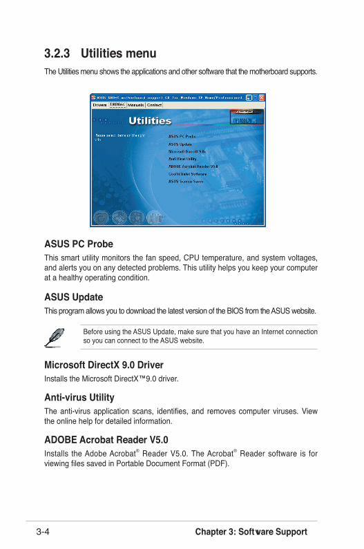
Chapter 3: Software Support3-4
ASUS PC ProbeThis smart utility monitors the fan speed, CPU temperature, and system voltages, and alerts you on any detected problems. This utility helps you keep your computer at a healthy operating condition.
ASUS UpdateThis program allows you to download the latest version of the BIOS from the ASUS website.
Before using the ASUS Update, make sure that you have an Internet connection so you can connect to the ASUS website.
Microsoft DirectX 9.0 DriverInstalls the Microsoft DirectX™9.0 driver.
Anti-virus Utility The anti-virus application scans, identifies, and removes computer viruses. View the online help for detailed information.
ADOBE Acrobat Reader V5.0Installs the Adobe Acrobat® Reader V5.0. The Acrobat® Reader software is for viewing files saved in Portable Document Format (PDF).
3.2.3 Utilities menuThe Utilities menu shows the applications and other software that the motherboard supports.

ASUS K8U-X Motherboard 3-5
Cool' n' Quiet SoftwareInstall Cool' n' Quiet.
ASUS Screen SaverInstalls the ASUS screen saver.
In different OS, the screen display may be different with the option of utility driver. The icons are for general reference only.
3.2.4 Manual menuThe Manual menu contains a list of supplementary user manuals. Click an item to open the manual.
Install the Adobe® Acrobat® Reader from the Utilities menu to open the manual files in PDF.
In different OS, the screen display may be different with the option of utility driver. The icons are for general reference only.
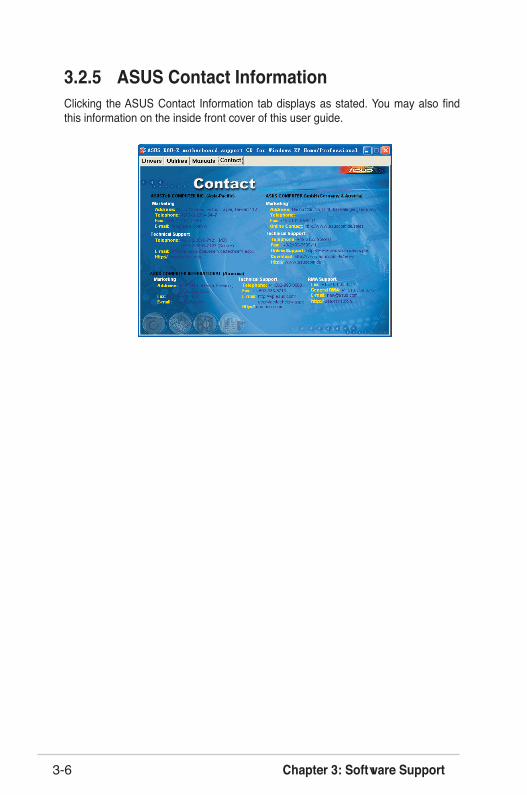
Chapter 3: Software Support3-6
3.2.5 ASUS Contact InformationClicking the ASUS Contact Information tab displays as stated. You may also find this information on the inside front cover of this user guide.
ASUS K8U-X Motherboard 3-7
3.3 RAID ConfigurationsThis onboard Southbridge Chipset ULi M1689 allow you to set HardDisk RAID. It supports RAID as follows:
RAID 0 (called data striping) optimizes two identical hard disk drives to read and write data in parallel, interleaved stacks. Two hard disks perform the same work as a single drive but at a sustained data transfer rate, double that of a single disk alone, thus improving data access and storage.
RAID 1 (called data mirroring) copies and maintains an identical image of data from one drive to a second drive. If one drive fails, the disk array management software directs all applications to the surviving drive as it contains a complete copy of the data in the other drive. This RAID configuration provides data protection and increases fault tolerance to the entire system.
JBOD (for “just a bunch of disks” or sometimes “just a bunch of drives”) is officially termed as “spanning”. This is used to refer to a computerʼs hard disks that havenʼt been configured according the RAID system to increase fault tolerance and improved data access performance. This RAID system stores the same data redundantly on multiple drives by combining the drives into one larger logical drive.
If you use either Windows® XP or Windows® 2000 operating system (OS), copy first the RAID driver from the support CD to a floppy disk before creating RAID configurations. Refer to section “3.4 Creating a RAID driver disk” for details.
3.3.1 Installing hard disksThe motherboard supports Serial ATA hard disk drives. For optimal performance, install identical drives of the same model and capacity when creating a disk array.
Installing SATA hard disksTo install the SATA hard disks for RAID configuration:1. Install the SATA hard disks into the drive bays.2. Connect the SATA signal cables.3. Connect the SATA power cable to the power connector on each drive.

Chapter 3: Software Support3-8
3.4 Creating a RAID Driver DiskTo create a RAID driver disk:
1. Insert the motherboard support CD into the CD-ROM drive and locate the Makedisk.exe utility for your RAID controller. The Makedisk.exe utility for the RAID driver is located in \Drivers\RAID\Makedisk.exe” of the motherboard support CD.
2. Insert a clean floppy disk into the floppy disk drive and execute Makedisk.exe. Follow succeeding screen instructions to complete the process.
3. Write-protect the floppy disk to avoid computer virus infection.
To create a RAID driver disk:
1. During the OS installation, the system prompts to press the F6 key to install third-party SCSI or RAID driver.
2. Press <F6> then insert the floppy disk with RAID driver into the floppy disk drive.3. Follow the succeeding screen instructions to complete the installation.
For additional information on RAID installation and configuration, refer to the readme file which is located in [Drivers\RAID\Readme.txt] in support CD.

ASUS K8U-X Motherboard 3-9
3.5 Cool ʻn ̓Quiet!™ TechnologyThe motherboard supports the AMD Cool ʻnʼ Quiet!™ Technology that dynamically and automatically change the CPU speed and voltage depending on the task the CPU performs.
Make sure to install the Cool ʻn ̓Quiet!™ driver and application when using this feature.
3.5.1 Enabling Cool ʻn ̓Quiet!™ TechnologyTo enable Cool ʻn ̓Quiet!™ technology:
1. Turn on the system and enter BIOS by pressing the <Del> key during the Power On Self-Tests (POST).
2. In the Advanced > CPU Configuration > AMD CPU Cool & Quiet Configuration menu, select the item Cool NʼQuiet and set it to Enabled. See section “2.4 Advanced Menu” for details.
3. In the Power menu, select the item ACPI 2.0 Support and set it to Yes. See section “2.5 Power Menu” for details.
4. Save your changes and exit BIOS Setup.5. Reboot your computer and set your Power Option Properties depending on
your operating system.
Windows® 2000/XP:
1. Make sure the Control Panel is set to Classic View.
2. From the Windows ® 2000/XP operating system, click the Start button. Select Settings , then Control Panel.
3. Double-click the Display icon in the Control Panel then select the Screen Saver tab.
4. Click the Power... button. The following dialog box appears.
5. From the Power schemes combo list box, select Minimal Power Management.
6. Click OK to effect settings.

Chapter 3: Software Support3-10
Windows® 98SE/ME
1. F r o m t h e W i n d o w s ® 9 8 S E / M E operating system, click the Start button. Select Settings, then Control Panel.
2. Double-click the Display icon in the Control Panel then select the Screen Saver tab.
3. From the Energy saving features of monitor group, click the Settings... button.
4. F r o m t h e P o w e r O p t i o n s Properties dialog box, select the AMDʼs Cool ʻn ̓Quiet(tm) Technology tab.
5. Click the Performance combo l i s t b o x t o s e l e c t d e s i r e d mode. Automatic Mode is the recommended setting.
6. Click OK to effect settings.
• Make sure to install the AMD Cool ʻnʼ Quiet!™ driver and application before using this feature.
• The AMD Cool ʻnʼ Quiet!™ Technology feature works only with the AMD heatsink and fan assembly with monitor chip.
• If you purchased a separate heatsink and fan package, use the ASUS Q-Fan Technology feature to automatically adjust your CPU fan speed according to your system loading.

ASUS K8U-X Motherboard 3-11
3.5.2 Launching the Cool ʻn ̓Quiet!™ softwareThe motherboard support CD includes the Cool ʻnʼ Quiet!™ software that enables you to view your systemʼs real-time CPU frequency and voltage.
To launch the Cool ʻn ̓Quiet!™ program:1. If you are using Windows® 98SE/ME/2000, click the Start button. Select
Programs > ASUS > Cool & Quiet > Cool & Quiet.2. If you are using Windows® XP, click the Start button. Select All Programs >
ASUS > Cool & Quiet > Cool & Quiet.3. The Cool ʻnʼ Quiet!™ technology screen appears and displays the current CPU
Frequency and CPU Voltage.
Make sure to install the Cool ʻnʼ Quiet!™ software from the motherboard support CD. Refer to section “3.2.3 Utilities” for details.

Chapter 3: Software Support3-12