K4 drive systems Brilliantly versatile - ebm-papstK4 drive systems K1 motor with control electronics...
24
K4 drive systems Brilliantly versatile Drive solutions | Industrial drive engineering 2017-11
Transcript of K4 drive systems Brilliantly versatile - ebm-papstK4 drive systems K1 motor with control electronics...

K4 drive systemsBrilliantly versatileDrive solutions | Industrial drive engineering 2017-11

2
2017
-11
About ebm-papst.
Six reasons that make us the ideal partner:
Our systems expertise.
You want the best solution for every project. The entire ventilation
system must thus be considered as a whole. And that’s what we
do – with motor technology that sets standards, sophisticated
electronics and aerodynamic designs – all from a single source
and perfectly matched.
Our spirit of invention.
We are also always able to develop customized solutions for you
with our versatile team of over 600 engineers and technicians.
Our lead in technology.
We are pioneers and leaders in the development of high-efficiency
EC technology. Already today almost all our products are also
available with GreenTech EC technology. The list of benefits is
long: higher efficiency, low maintenance, longer service life,
sound reduction, intelligent control characteristics and unrivalled
energy efficiency.
Closeness to our customers.
ebm-papst has 25 production locations worldwide (including facilities
in Germany, China and the USA), together with 49 sales offices, each of
which has a dense network of sales representatives. You will always
have a local contact, someone who speaks your language and knows
your market.
Our standard of quality.
Our quality management is uncompromising, at every step in every
process. This is underscored by our certification according to inter-
national standards including DIN EN ISO 9001, TS declaration of
conformity and DIN EN ISO 14001.
Our sustainable approach.
Assuming responsibility for the environment, for our employees and
for society is an integral part of our corporate philosophy. We develop
products with an eye to maximum environmental compatibility,
in particular resource-preserving production methods. We promote
environmental awareness among our young staff and are actively
involved in sports, culture and education. That’s what makes us a
leading company – and an ideal partner for you.
As technological leader for ventilation and drive engineering, ebm-papst is in demand as an engineering partner in many industries. With over 15,000 different products, we provide the right solution for just about any challenge. Our fans and drives are reliable, quiet and energy-efficient.
2
ebm15060_Toolbox_Unternehmenstext_1/1-Seite_en_20170123.indd 1 10.02.17 11:47

3
2017
-11
Info
rmat
ion
K4 d
rive
syst
ems
K1 m
otor
with
con
trol
ele
ctro
nics
Acce
ssor
ies
ebm
-pap
st a
roun
d th
e w
orld
Information About ebm-papst 2The K4 can do (almost) everything 4
K4 motorsVDC-49.15-K4 8ECI-63.XX-K4 10
K1 Motor combined with external control electronicsECI-80.XX-K1 16VTD-XX.XX-K4S (position) 17
Accessories Commissioning tools 20Integration in Profinet networks 21
ebm-papst around the world 23
Contents.
4
2017
-11
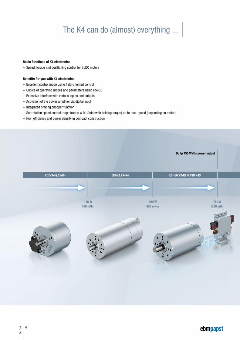
The K4 can do (almost) everything ...
Basic functions of K4 electronics
– Speed, torque and positioning control for BLDC motors
Benefits for you with K4 electronics
– Excellent control mode using field-oriented control
– Choice of operating modes and parameters using RS485
– Extensive interface with various inputs and outputs
– Activation of the power amplifier via digital input
– Integrated braking chopper function
– Set rotation speed control range from n = 0 U/min (with holding torque) up to max. speed (depending on motor)
– High efficiency and power density in compact construction
VDC-3-49.15-K4 ECI-63.XX-K4 ECI-80.XX-K1 & VTD K4S
125 W300 mNm
400 W850 mNm
750 W1800 mNm
Up tp 750 Watts power output

5
2017
-11
Info
rmat
ion
K4 d
rive
syst
ems
K1 m
otor
with
con
trol
ele
ctro
nics
Acce
ssor
ies
ebm
-pap
st a
roun
d th
e w
orld
Operating it is like child's play
– Parameterization and commissioning using PC software „Kickstart”
– Intuitive operation even without knowledge of programming languages
– No BUS knowledge required

6
2017
-11
7
2017
-11
Info
rmat
ion
K4 d
rive
syst
ems
K1 m
otor
with
con
trol
ele
ctro
nics
Acce
ssor
ies
ebm
-pap
st a
roun
d th
e w
orld
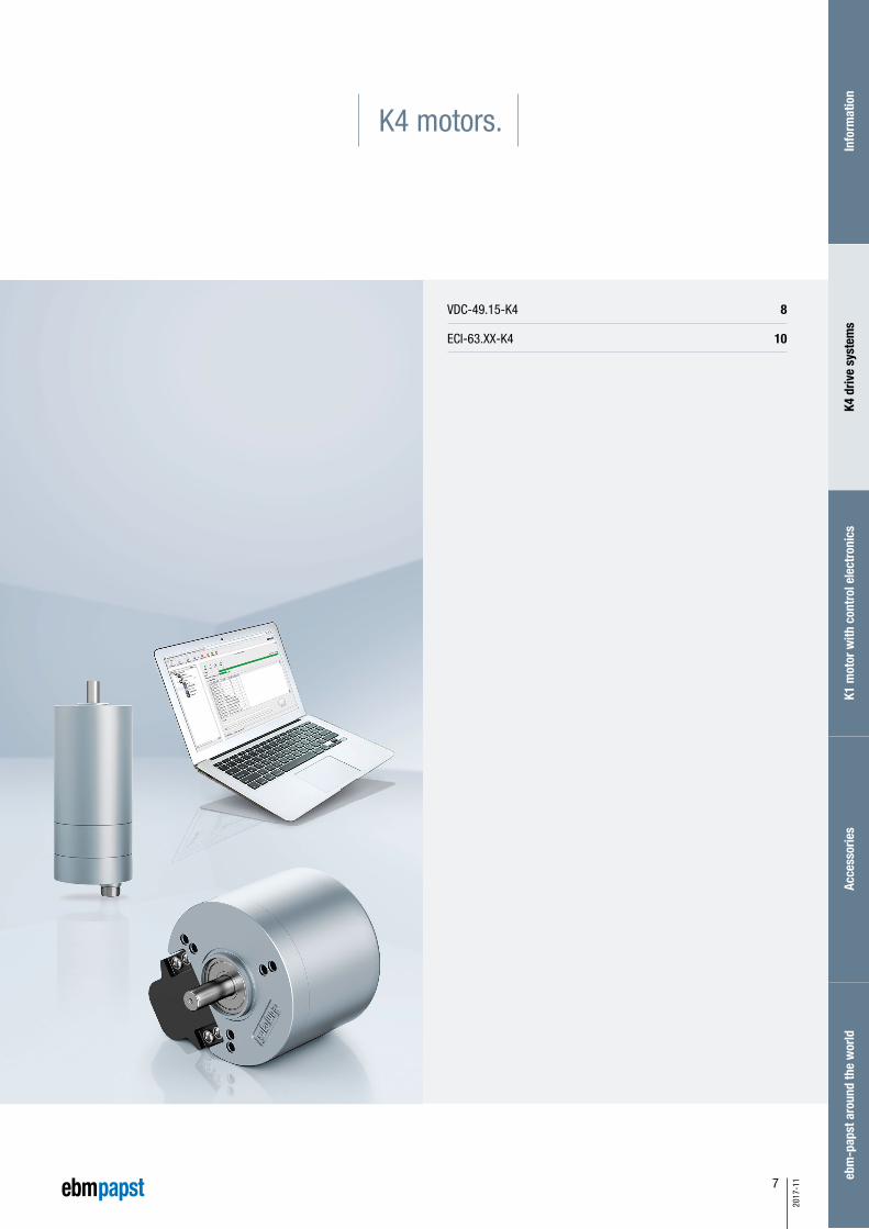
K4 motors.
VDC-49.15-K4 8
ECI-63.XX-K4 10

8
2017
-11
– 3-phase external rotor motor with EC technology
– High-poled motor structure for optimum power density.
– Drive with completely integrated K4 operation and control electronics
– Integrated speed, torque and position control
– Selection of operating modes and parameter setting via RS485
– Interface with analog and digital control inputs
– Integrated brake chopper
– Robust mechanical design in IP 54 for industrial applications
– Electrical connection via cable with free wire ends
VDC motor.VDC-49.15-K4
Characteristic curve
1) Nominal data, see table1) Nominal data, see table
VDC-49.15-K4-B00 (at 25°C) VDC-49.15-K4-D00 (at 25°C)
Nominal data
Type VDC-49.15-K4-B00 VDC-49.15-K4-D00
Nominal voltage (UN) V DC 24 48
Nominal speed (nN)* rpm 4 000
Nominal torque (MN)* mNm 235 300
Nominal current (IN)* A 5.20 3.20
Nominal output power (PN)* W 99 126
Starting torque (Mmax) mNm 705 900
Permissible peak current (Imax)** A 15.6 9.60
Speed at no-load operation (nL) rpm 5 000
No-load current (IL) A 0.40 0.25
Recommended speed control range rpm 0 ... 4 000
Rotor moment of inertia (JR) kgm2 x10–6 108
Overload protection integrated
Permissible ambient temperature range (TU) °C 0 ... +40
Weight kg 0.59
Order no. (cable type)*** IP 54 937 4915 400 937 4915 402
Subject to alterations * At TU max. 40°C** Permissible time for peak current: max. 1 sec. – to be repeated only after complete cool down*** Classification of protection class refers to installed state with sealing on the flange sidePreferred type: ready to ship in 48 hours
6 000
5 000
4 000
3 000
2 000
1 000
0
20,0
16,7
13,3
10,0
6,7
3,3
0
MN
0 100 200 300 400 500 600 700 800
MMax
100
90
80
70
60
50
40
30
20
10
0
Effic
ienc
y
[%
]
Torque M [mNm]
Curr
ent I
[A]
Continuous operation
Spee
d n
[min
-1]
Short-time operation
6 000
5 000
4 000
3 000
2 000
1 000
0
20,0
16,7
13,3
10,0
6,7
3,3
0
MN
0 100 200 300 400 500 600 700 800 900 1 000 1100 1 200
MMax
100
90
80
70
60
50
40
30
20
10
0
Effic
ienc
y
[%
]
Torque M [mNm]
Curr
ent I
[A]
Continuous operation
Spee
d n
[min
-1]
Short-time operation

9
2017
-11
Modular construction kit
Faxial 20 N
Fradial 60 N
L1 10 mm
Planetary gearheads
NoiselessPlus 63
Performax® 63
Performax®Plus 63
Crown gearheads
EtaCrown® 75
EtaCrown®Plus 63
Spur gearheads
Compactline 91
Flatline 85
Technical drawing
Electrical connection / cable with open wires
All dimensions in mm
Faxial
Fradial
L1* For thread-rolling screws according to DIN 7500
Wire color Configuration FunctionRecommended
AWG
Sign
al
white D-IN-A NPN 24 V
24
brown D-IN-B NPN 24 V
green D-IN-1 NPN 24 V
yellow D-IN-2 NPN 24 V / analog 0 ... 10 V / brake
gray D-OUT-1 PNP 24 V
pink D-OUT-2 PNP 24 V
blue – Must not be used
red A-IN-1 0 ... 10 V (differential)
black A-GND GND for analog IN 1 (differential)
violet RS485 A (+) Progr. bus
gray / pink RS485 B (–) Progr. bus
red / blue ULogic Logic power supply (24 V)
Pow
er
gray Ballast Ballast resistor
16brown UZK Power supply
black GND Power / signal GND
Basic motor
52±0.5 20±0.3
2.5±0.1
500±10
24±0.585±5
Ø7.2
±0.
15
twisted and tin-plated
Ø 25
h8
Ø 8+
0.00
6+
0.01
0
4±0.5
24±0.2
Ø 40
Ø 50
Ø 63±0.2
3x12
0°
44.6
5±0.
5
R 35
grooves for O-ring
6x hole* M4
Permissible shaft load at nominal speedand life expectancy L10 (nominal operation) of 20 000 h (at TU max. 40°C)
Commissioning tool
“Kickstart”
Info
rmat
ion
K4 d
rive
syst
ems
K1 m
otor
with
con
trol
ele
ctro
nics
Acce
ssor
ies
ebm
-pap
st a
roun
d th
e w
orld

10
2017
-11
– Drive with completely integrated 4Q operation and control electronics
– Speed, torque or position mode possible
– Selection of operating modes and parameter setting via RS485
– Extensive interface with various inputs and outputs
– Output stage enabled via digital input
– Integrated brake chopper
– Speed set values from n=0 with holding torque up to 5 000 rpm
– Excellent control behavior via field-oriented control
with sine commutation
– High efficiency and high power density realized in a compact design
– User-friendly parameter setting with “Kickstart” PC software
ECI motor.ECI-63.XX-K4
Nominal data
TypeECI-63.20-K4
-B00ECI-63.20-K4
-D00ECI-63.40-K4
-B00ECI-63.40-K4
-D00ECI-63.60-K4
-D00
Nominal voltage (UN) V DC 24 48 24 48 48
Permissible supply voltage range (UZK) V DC 18 ... 30 18 ... 53 18 ... 30 18 ... 53 18 ... 53
Max. reverse voltage V DC 35 58 35 58 58
Nominal speed (nN) rpm 4 000
Nominal torque (MN)** mNm 425 450 600 750 850
Nominal current (IN)** A 8.50 5.40 12.3 7.20 8.60
Nominal output power (PN)** W 178 188 251 314 356
Starting torque (Mmax) mNm 1 480 1 890 1 500 3 000 2 550
Speed at no-load operation (nL) rpm 5 800 5 800 5 900 5 800 6 000
No-load current (IL) A 0.50 0.50 0.90 0.50 0.60
Recommended speed control range rpm 0 ... 5 000
Set value input analog / PWM / frequency / digital
Rotor moment of inertia (JR) kgm2 x10–6 19 19 38 38 57
Function for motor protection at stall thermal
Overload protection integrated
Permissible ambient temperature range (TU) °C 0 ... +40
Weight kg 0.85 0.85 1.15 1.15 1.50
Order no. (wire interface)* IP 40 932 6320 403 932 6320 405 932 6340 403 932 6340 405 932 6360 405
Order no. (connector interface)* IP 54 932 6320 400 932 6320 402 932 6340 400 932 6340 402 932 6360 402
Subject to alterations * Classification of protection class refers to installed state with sealing on the flange side** At TU max. 40°CPreferred type: ready to ship in 48 hours

11
2017
-11
0 150 300 450 600 750 12001050900
7 000
6 000
5 000
4 000
3 000
2 000
1 000
01250
MN MMax
70
60
50
40
30
20
10
0
100
90
80
70
60
50
40
30
20
10
0
Torque M [mNm]
Spee
d n
[min
-1]
Curr
ent I
[A]
Short-time operation
Effic
ienc
y
[%
]
Continuousoperation
7 000
6 000
5 000
4 000
3 000
2 000
1 000
0
MN MMax
70
60
50
40
30
20
10
00 300 600 900 1200 1500 1800 2100 2400 2600
100
90
80
70
60
50
40
30
20
10
0
Torque M [mNm]
Spee
d n
[min
-1]
Curr
ent I
[A]
Short-time operation
Effic
ienc
y
[%
]
Continuousoperation
7 000
6 000
5 000
4 000
3 000
2 000
1 000
0
MN MMax
70
60
50
40
30
20
10
00 150 300 450 600 750 900 1050 1200 1300
100
90
80
70
60
50
40
30
20
10
0
Torque M [mNm]
Spee
d n
[min
-1]
Curr
ent I
[A]
Short-time operation
Effic
ienc
y
[%
]
Continuousoperation
1) Nominal data, see table
1) Nominal data, see table
1) Nominal data, see table
Characteristic curve
ECI-63.20-K4, 24 V (at 25°C)
ECI-63.60-K4, 48 V (at 25°C)
ECI-63.40-K4, 24 V (at 25°C)
Characteristic curve 48 V on request Characteristic curve 48 V on request
Info
rmat
ion
K4 d
rive
syst
ems
K1 m
otor
with
con
trol
ele
ctro
nics
Acce
ssor
ies
ebm
-pap
st a
roun
d th
e w
orld

12
2017
-11
12
7
11
8
10
9
3
BAC
4
2
5
1
6
ECI motor.ECI-63.XX-K4
Technical drawing
Electrical connection
Wire color Pin Configuration FunctionRecommended
AWG
Sign
al
white 1 D-IN-A NPN 24 V
24
brown 2 D-IN-B NPN 24 V
green 3 D-IN-1 NPN 24 V
yellow 4 D-IN-2 NPN 24 V / analog 0 ... 10 V / brake
gray 5 D-OUT-1 PNP 24 V
pink 6 D-OUT-2 PNP 24 V
blue 7 D-OUT-3* PNP 24 V
red 8 A-IN-1 0 ... 10 V (differential)
black 9 A-IN-GND GND for analog IN 1 (differential)
violet 10 RS485 A (+) Progr. bus
gray / pink 11 RS485 B (–) Progr. bus
red / blue 12 ULogic Logic power supply (24 V)
Pow
er
gray A Ballast Ballast resistor
16brown B UZK Power supply
black C GND Power / signal GND
* Output (OUT 3) is only available on ECI-63.XX-K4
All dimensions in mm
Type L Ø D
ECI-63.20 118.5 ± 0.3 6g5
ECI-63.40 138.5 ± 0.3 6g5
ECI-63.60 158.5 ± 0.3 10g5
5.8
Ø 63
.5
4 x 90°
30°
4 x 90
°
10 deep
10 deep
5 deep
Ø 63
±0.
2
M5
R 20
.25±0.1
(16.3)
Ø 49
Ø 40
Ø 36
L
Ø 25
-0.
04
20±0.3
ØD
2±0.1M
16
4 x hole* for M5
8 x hole* for M4
* For thread-rolling screws according to DIN 7500
Faxial 150 N
Fradial 150 N
L1 20 mm
Faxial
Fradial
L1
Permissible shaft load at nominal speedand life expectancy L10 (nominal operation) of 20 000 h (at TU max. 40°C)

13
2017
-11
Cable
Modular construction kit
Basic motor
Type Length L (mm) Order no.
Cable (12+3 Pins) 1 000 ±30 992 0160 034
Cable (12+3 Pins) 3 000 ±30 992 0160 035
Type Length L (mm) Order no.
Cable (12+3 Pins) 1 000 ±30 992 0160 036
Cable (12+3 Pins) 3 000 ±30 992 0160 037
Planetary gearheads
NoiselessPlus 63
Performax® 63
Performax®Plus 63
Optimax 63
Crown gearheads
EtaCrown® 75
EtaCrown®Plus 63
For motor-gearbox combinations, depending on the choice of the single components, the maximum allowable torque (gearbox) can be exceeded or respectively not reached.
Cable
Connection cables have to be ordered separately
Commissioning tool
“Kickstart”
Hummel cable connector M16 for cable Ø 8-11 mm, Tightening torque: 5 Nm (Order no. 7.810.500.000)
Hummel crimp insert series M16, socket 12+3 with special coding (Order no. 7K11886034)
Hummel crimp contact socket 3 x, power, crimp range 0.5 - 1.5 mm2 (Order no. 7.010.981.202)
Hummel crimp contact socket 12 x, signal, crimp range 0.08 - 0.34 mm2 (Order no. 7.010.980.802)
For self-assembly, cables can be obtained from Hummel:
Brake system
Spring-applied brake, integrated
Brake module ECI 63-K4
Info
rmat
ion
K4 d
rive
syst
ems
K1 m
otor
with
con
trol
ele
ctro
nics
Acce
ssor
ies
ebm
-pap
st a
roun
d th
e w
orld
You can find an overview of our drive
systems with technical data in our main
catalogues ECI and VD/VDC.

14
2017
-11
15
2017
-11
Info
rmat
ion
K4 d
rive
syst
ems
K1 m
otor
with
con
trol
ele
ctro
nics
Acce
ssor
ies
ebm
-pap
st a
roun
d th
e w
orld
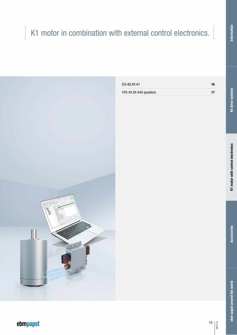
K1 motor in combination with external control electronics.
ECI-80.XX-K1 16
VTD-XX.XX-K4S (position) 17

16
2017
-11
– Highly dynamic 3-phase internal rotor motor with EC technology
– Low cogging torque
– Robust, noise-optimized ball bearing system for a long service life
– High efficiency and high power density realized in a compact design
– Protection class IP 40/IP 54 and connection by connector system
– Basic motor with electronic module K1 for operation with external
control electronics
– Mechanical design and interfaces designed for modular flexibility
ECI motor.ECI-80.XX-K1
Nominal data
TypeECI-80.20-K1
-B00ECI-80.20-K1
-D00ECI-80.40-K1
-B00ECI-80.40-K1
-D00ECI-80.60-K1
-D00
Nominal voltage (UN) V DC 24 48 24 48 48
Nominal speed (nN)* rpm 4 000
Nominal torque (MN)* mNm 700 700 1 200 1 200 1 800
Nominal current (IN)* A 13.5 7.50 25.0 12.0 18.0
Nominal output power (PN)* W 293 293 503 503 754
Starting torque (Mmax) mNm 2 400 2 500 3 900 5 000 5 600
Permissible peak current (Imax)** A 100 60 100 100 100
Permanent stall torque (MNO) mNm 700 700 1 200 1 200 1 800
Speed at no-load operation (nL) rpm 1.00 0.70 1.50 0.90 1.00
No-load current (IL) A 0 ... 4 000
Speed at no-load operation (nL) rpm 4 800 4 800 4 700 4 850 6 100
Rotor moment of inertia (JR) kgm2 x10–6 54 54 104 104 155
Motor constant (KE) mVs/rad 47.2 94.1 48.2 96.0 72.15
Connection resistance (RV) Ω 0.07 0.30 0.03 0.10 0.04
Connection inductance (LV) mH 0.30 1.30 0.20 0.60 0.20
Overload protection integrated
Permissible ambient temperature range (TU) °C -30 ... +40
Weight kg 1.40 1.40 2.10 2.10 2.70
Order no. (wire interface)*** IP 40 932 8020 103 932 8020 105 932 8040 103 932 8040 105 932 8060 105
Order no. (cable routing)*** IP 54 On request
Subject to alterations * At TU max. 40°C** Permissible time for peak current: max. 5 sec. – to be repeated only after complete cool down*** Classification of protection class refers to installed state with sealing on the flange side

17
2017
-11
Control electronics.VTD-XX.XX-K4S
– Operating electronics for driving 3-phase BLDC motors
up to 1 000 watt output power
– Four-quadrant controller
– Speed, torque and positioning mode
– Selection of operating modes and parameter setting via RS 485
– User-friendly parameter setting with “Kickstart” PC software
– Integrated brake ballast-control
– Device status notification by 2 LEDs
Nominal data
Type VTD-24.40-K4S VTD-48.20-K4S
Nominal voltage (power supply UN) V DC 24 48
Permissible supply voltage range (U) V DC 18 ... 30 18 ... 53
Maximum output current (max. 5 sec)* A 100
Permissible continuous output current* A 40 ± 10% 20 ± 10%
Nominal voltage (Logic supply UL) V DC 24
Logic current draw** (at 24 V DC) mA < 100
Maximum commutation frequency kHz 2
Switching frequency kHz 20
Minimum connection inductance mH 0.10
Digital inputs Number 4
Digital outputs Number 3
Analog inputs Number 1
Parameterization interface RS 485
Efficiency (in optimum working range) % > 95
Permissible ambient temperature range (TU) °C -30 ... +40
Permissible ambient humidity*** % 5 ... 85
Protection class IP 20
Weight kg approx. 0.50
Order number (IP 20) 994 2440 000 994 4820 000
Subject to alterations
Series planned for 2nd q/2017
* Applicable at rated temperature TU = 25°C, Derating at deviating (higher) temperatures ** Current draw without current requirement of digital outputs*** Condensation not permitted
Info
rmat
ion
K4 d
rive
syst
ems
K1 m
otor
with
con
trol
ele
ctro
nics
Acce
ssor
ies
ebm
-pap
st a
roun
d th
e w
orld

18
2017
-11
4 x 90°
4 x
90°
45° 45°2 x 6
0°
°09 x 4
13 deep
13 deep
Ø 80
±0.
2
Ø 45
Ø 56
Ø 60
L1
L2 30±0.3
3±0.1
Ø 15
+0.
009
+0.
015
Ø 32
-0.0
5
8 x hole* for M6
4 x hole* for M5
Technical drawing
ECI motor.ECI-80.XX-K1
All dimensions in mm
Type L1 L2
ECI-80.20 96 ± 0.3 89 ± 0.3
ECI-80.40 116 ± 0.3 109 ± 0.3
ECI-80.60 136 ± 0.3 129 ± 0.3
* For thread-rolling screws according to DIN 7500
Faxial 70 N
Fradial 330 N
L1 15 mm
Faxial
Fradial
L1
Permissible shaft load at nominal speedand life expectancy L10 (nominal operation) of 20 000 h (at TU max. 40°C)
7 000
6 000
5 000
4 000
3 000
2 000
1 000
0
MN MMax
120
100
80
60
40
20
00 200 400 2000600 800 1000 1200 1400 1600 1800
100
90
80
70
60
50
40
30
20
10
0
Torque M [mNm]
Spee
d n
[min
-1]
Curr
ent I
[A]
Short-time operation
Effic
ienc
y
[%
]
Continuousoperation
7 000
6 000
5 000
4 000
3 000
2 000
1 000
0
MN MMax
120
100
80
60
40
20
00 500 1000 50001500 2000 2500 3000 3500 4000 4500
100
90
80
70
60
50
40
30
20
10
0
Torque M [mNm]
Spee
d n
[min
-1]
Curr
ent I
[A]
Short-time operation
Effic
ienc
y
[%
]
Continuousoperation
7 000
6 000
5 000
4 000
3 000
2 000
1 000
0
MN MMax
120
100
80
60
40
20
00 400 800 1200 1600 2000 2400 2800 3200 3600
100
90
80
70
60
50
40
30
20
10
0
Torque M [mNm]
Spee
d n
[min
-1]
Curr
ent I
[A]
Short-time operation
Effic
ienc
y
[%
]
Continuousoperation
1) Nominal data, see table
1) Nominal data, see table
1) Nominal data, see table
Characteristic curve
ECI-80.20-K1, 24 V (at 25°C)
ECI-80.60-K1, 48 V (at 25°C)
ECI-80.40-K1, 24 V (at 25°C)
Characteristic curve 48 V on request Characteristic curve 48 V on request

19
2017
-11
96 41
157
X 106
X 100
X 102
X 107
X 101
Status LEDs
Basic motor
Modular construction kit for ECI 80 motor
Planetary gearheads
Performax®Plus 63
Optimax 63
For motor-gearbox combinations, depending on the choice of the single components, the maximum allowable torque (gearbox) can be exceeded or respectively not reached.
Brake system
On request
Encoder system
On request
Technical drawing control electronics All dimensions in mm
Mating connectors are included in delivery
PC with software“Kickstart”
Power supply
Controller
Motor
Control electronics
Interface adapterOrder no. 914 0000 400
Accessories setup
Image of “Kickstart” PC software
“Kickstart” PC software for commissioning/ parametrization of the drive controller
Commissioning tool
“Kickstart”
Commissioning setup
Info
rmat
ion
K4 d
rive
syst
ems
K1 m
otor
with
con
trol
ele
ctro
nics
Acce
ssor
ies
ebm
-pap
st a
roun
d th
e w
orld
You can find an overview of the
electrical connection in our main
catalogues ECI and VD/VDC.
PLC
20
2017
-11
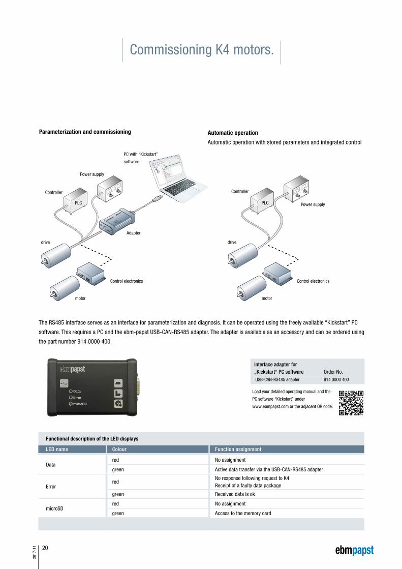
Commissioning K4 motors.
Parameterization and commissioning Automatic operation
Automatic operation with stored parameters and integrated control
Load your detailed operating manual and the
PC software “Kickstart” under
www.ebmpapst.com or the adjacent QR code:
Interface adapter for „Kickstart“ PC software Order No. USB-CAN-RS485 adapter 914 0000 400
The RS485 interface serves as an interface for parameterization and diagnosis. It can be operated using the freely available “Kickstart” PC
software. This requires a PC and the ebm-papst USB-CAN-RS485 adapter. The adapter is available as an accessory and can be ordered using
the part number 914 0000 400.
Functional description of the LED displays
LED name Colour Function assignment
Datared No assignment
green Active data transfer via the USB-CAN-RS485 adapter
Errorred
No response following request to K4Receipt of a faulty data package
green Received data is ok
microSDred No assignment
green Access to the memory card
PC with “Kickstart”
software
Power supply
Controller
Adapter
drive
Controller
Power supply
drive
motor motor
Control electronics Control electronics
PLC PLC

21
2017
-11
Schematic layout
– The RS485 interface available on the compact drive allows
integration into Profinet networks
– Functional components allow simple control
Advantages
– Automatic parameterization of the drive
(K4 knowledge not required)
– Automatic controller setting
– Application setting in physical values
– Various statistics and diagnostic information
– Speed/position commands
– Automatic determination of the start-up time
using integrated mechatronic model
– HMI control displays allow intuitive interaction
Easy integration into Profinet networks.
VDC-49.15-K4ECI-63.XX-K4VTD-XX.XX-K4S
ECI-80.XX-K1
The SIEMENS ET 200SP allows easy integration of our K4 drivers
in the Profitnet networks via communication module CM PtP
Info
rmat
ion
K4 d
rive
syst
ems
K1 m
otor
with
con
trol
ele
ctro
nics
Acce
ssor
ies
ebm
-pap
st a
roun
d th
e w
orld
22
2017
-11
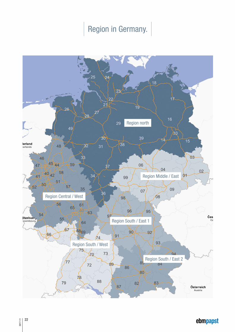
Region in Germany.
Region north
Region Middle / East
Region Central / West
Region South / East 1
Region South / East 2
Region South / West

23
2017
-11
ebm-papst around the world.
ebm-papst St. Georgen GmbH & Co. KGHermann-Papst-Straße 178112 St. GeorgenGermanyPhone +49 7724 81-0Fax +49 7724 [email protected]
ebm-papst ZEITLAUF GmbH & Co. KGIndustriestraße 991207 Lauf a. d. PegnitzGermanyPhone +49 9123 945-0Fax +49 9123 [email protected]
Germany
Northern regionNorderstedtBreuell & Hilgenfeldt GmbHUdo Wildenblanck Regional Sales Manager – Drive TechnologyOststraße 9622844 NorderstedtPhone +49 9123 945-291Fax +49 9123 [email protected]
Central / eastern regionSouthern / eastern region 1Dipl. oec. (VWA) Henry SämischWaldweg 315926 LuckauPhone +49 9123 945-292Fax +49 9123 [email protected]
Central / western regionMarkus PsikAm Dreispitz 1669502 HemsbachPhone +49 9123 945-293Fax +49 9123 [email protected]
Southern / western regionMeißenheimMichael WeberKarlstraße 1777974 MeißenheimPhone +49 9123 945-294Fax +49 9123 [email protected]
Southern / eastern region 2MunichDipl. Eng. (Univ.) Patrick ChristlevenFaustnerweg 1081479 MunichPhone +49 9123 945-295Fax +49 9123 [email protected]
Europe
Franceebm-papst sarlParc d’Activités Nord1 rue Mohler – BP 6267212 Obermai CedexPhone +33 3 88 66 88 [email protected]
Great Britainebm-papst Automotive & Drives (UK) Ltd.The SmithyFidlers LaneEast Ilsley, Berkshire RG20 7LGPhone +44 1635 2811-11Fax +44 1635 [email protected]
Italyebm-papst SrlVia Cornaggia 10822076 Mozzate (Co)Phone +39 0331 8362013Fax +39 0331 [email protected]
Beneluxebm-papst Benelux B.V.Polbeemd 7 – 5741 TP Beek en DonkP.O. Box 140 – 5740 AC Beek en DonkPhone +31 492 502-900Fax +31 492 [email protected]
Austria ebm-papst Motoren & Ventilatoren GmbHStraubingstraße 174030 LinzPhone +43 732 321150-0Fax +43 732 [email protected]
Russiaebm-papst Rus GmbHOlimpiyskiy prospect 29A, office 418141006 Mytistschi, Oblast MoscowPhone +7 495 9807524Fax +7 795 [email protected]
Swedenebm-papst ABÄggelundavägen 217562 JärfällaPhone +46 10 4544400Fax +46 8 [email protected]
Switzerlandebm-papst AGRütisbergstraße 1t8156 OberhasliPhone +47 44 73220-70Fax +41 44 [email protected]
America
USAebm-papst Automotive & Drives Inc.3200 Greenfield, Suite130Dearborn, MI 48120Phone +1 313 406-8080Fax +1 313 [email protected]
Asia
Chinaebm-papst Ventilator (Shanghai) Co., LtdNo. 418, Huajing RoadWaiGaoQiao Free Trade Zone200131 ShanghaiPhone +86 21 5046-0183Fax +86 21 [email protected] www.ebmpapst.com.cn
Indiaebm-papst India Pvt. Ltd.26/3, G.N.T. Road Erukkencherry600 118 ChennaiPhone +91 44 26720103Fax +91 44 [email protected] www.ebmpapst.in
Motor specialist Motor representative
Info
rmat
ion
K4 d
rive
syst
ems
K1 m
otor
with
con
trol
ele
ctro
nics
Acce
ssor
ies
ebm
-pap
st a
roun
d th
e w
orld
www.ebmpapst.com 37891-7-8811 ∙ 2017-11 ∙ WA-2`
ebm-papst
St. Georgen GmbH & Co. KG
Hermann-Papst-Straße 1
78112 St. Georgen
Germany
Phone +49 7724 81-0
Fax +49 7724 81-1309
ebm-papst ZEITLAUF
GmbH & Co. KG
Industriestraße 9
91207 Lauf a. d. Pegnitz
Germany
Phone +49 9123 945-0
Fax +49 9123 945-145