K3M: A UNIVERSAL ALGORITHM FOR IMAGE SKELETONIZATION AND A REVIEW OF
19
Int. J. Appl. Math. Comput. Sci., 2010, Vol. 20, No. 2, 317–335 DOI: 10.2478/v10006-010-0024-4 K3M: A UNIVERSAL ALGORITHM FOR IMAGE SKELETONIZATION AND A REVIEW OF THINNING TECHNIQUES KHALID SAEED ∗ ,MAREK TAB ˛ EDZKI ∗∗ ,MARIUSZ RYBNIK ∗∗∗ ,MARCIN ADAMSKI ∗∗ ∗ Faculty of Physics and Applied Computer Science AGH University of Science and Technology, Al. Mickiewicza 30, 30–059 Cracow, Poland e-mail: [email protected] ∗∗ Faculty of Computer Science Bialystok Technical University, ul. Wiejska 45 A, 15–351 Bialystok, Poland e-mail: {m.tabedzki,m.adamski}@pb.edu.pl ∗∗∗ Faculty of Mathematics and Informatics University of Bialystok, ul. M. Sklodowskiej-Curie 14, 15–097 Bialystok, Poland e-mail: [email protected] This paper aims at three aspects closely related to each other: first, it presents the state of the art in the area of thinning methodologies, by giving descriptions of general ideas of the most significant algorithms with a comparison between them. Secondly, it proposes a new thinning algorithm that presents interesting properties in terms of processing quality and algorithm clarity, enriched with examples. Thirdly, the work considers parallelization issues for intrinsically sequential algorithms of thinning. The main advantage of the suggested algorithm is its universality, which makes it useful and versatile for a variety of applications. Keywords: skeletonization, thinning, digital image processing, parallelization, iteration, thinning methodologies, sequen- tial thinning, parallel thinning. 1. Introduction As a digital image processing technique, thinning has be- en around for many years. Thinning (also termed skele- tonization) is an image pre-processing technique that is important in a number of applications like pattern reco- gnition, data compression and data storage (Gonzalez and Woods, 2007). The history of thinning covers over fifty years. In the 1950s Dinnen (1955) found that an averaging operation over a square window with a high threshold re- sulted in a thinning of the input image. Then Kirsch et al. (1958) mentioned that the “custer” operation was an early attempt to obtain a thinline representation of certain cha- racter patterns. However, still there is no ultimate solution suitable for each individual area of application (Jaisimha et al., 1994; Jang and Chin, 1992; Lam et al., 1992; Lee et al., 1991). This is due to the complicated nature of the processing as well as various evaluation measures that should be considered. There are more than one thousand algorithms that ha- ve been published on this topic. The thinning algorithms mentioned in this paper have been selected from among the best known published works. These selected works are given here for comparison to show and evaluate the ef- forts of other researchers and authors in working out and implementing a number of algorithms and approaches for a variety of applications. The first trials conducted in this field by the au- thors of this paper date back to 1999 (Saeed and Nie- dzielski, 1999). This was to aid recognition algorithms of cursive-character letters, which required thinning before classification. This work is an attempt to propose a new criterion and employ it to various applications. The pre- sented method leads to a fast recognition algorithm of both typewritten and handwritten texts with the possibility of applying it to thin images of a variety of objects. The ba- sic idea of thinning according to this approach lies in the generation of a skeleton with a one-pixel width. Howe- ver, to serve more complicated cases, some modifications
Transcript of K3M: A UNIVERSAL ALGORITHM FOR IMAGE SKELETONIZATION AND A REVIEW OF
Int. J. Appl. Math. Comput. Sci., 2010, Vol. 20, No. 2, 317–335DOI: 10.2478/v10006-010-0024-4
K3M: A UNIVERSAL ALGORITHM FOR IMAGE SKELETONIZATIONAND A REVIEW OF THINNING TECHNIQUES
KHALID SAEED ∗, MAREK TABEDZKI ∗∗, MARIUSZ RYBNIK ∗∗∗, MARCIN ADAMSKI ∗∗
∗ Faculty of Physics and Applied Computer ScienceAGH University of Science and Technology, Al. Mickiewicza 30, 30–059 Cracow, Poland
e-mail: [email protected]
∗∗Faculty of Computer ScienceBiałystok Technical University, ul. Wiejska 45 A, 15–351 Białystok, Poland
e-mail: m.tabedzki,[email protected]
∗∗∗Faculty of Mathematics and InformaticsUniversity of Białystok, ul. M. Skłodowskiej-Curie 14, 15–097 Białystok, Poland
e-mail: [email protected]
This paper aims at three aspects closely related to each other: first, it presents the state of the art in the area of thinningmethodologies, by giving descriptions of general ideas of the most significant algorithms with a comparison betweenthem. Secondly, it proposes a new thinning algorithm that presents interesting properties in terms of processing qualityand algorithm clarity, enriched with examples. Thirdly, the work considers parallelization issues for intrinsically sequentialalgorithms of thinning. The main advantage of the suggested algorithm is its universality, which makes it useful and versatilefor a variety of applications.
Keywords: skeletonization, thinning, digital image processing, parallelization, iteration, thinning methodologies, sequen-tial thinning, parallel thinning.
1. Introduction
As a digital image processing technique, thinning has be-en around for many years. Thinning (also termed skele-tonization) is an image pre-processing technique that isimportant in a number of applications like pattern reco-gnition, data compression and data storage (Gonzalez andWoods, 2007). The history of thinning covers over fiftyyears. In the 1950s Dinnen (1955) found that an averagingoperation over a square window with a high threshold re-sulted in a thinning of the input image. Then Kirsch et al.(1958) mentioned that the “custer” operation was an earlyattempt to obtain a thinline representation of certain cha-racter patterns. However, still there is no ultimate solutionsuitable for each individual area of application (Jaisimhaet al., 1994; Jang and Chin, 1992; Lam et al., 1992; Leeet al., 1991). This is due to the complicated nature ofthe processing as well as various evaluation measures thatshould be considered.
There are more than one thousand algorithms that ha-
ve been published on this topic. The thinning algorithmsmentioned in this paper have been selected from amongthe best known published works. These selected works aregiven here for comparison to show and evaluate the ef-forts of other researchers and authors in working out andimplementing a number of algorithms and approaches fora variety of applications.
The first trials conducted in this field by the au-thors of this paper date back to 1999 (Saeed and Nie-dzielski, 1999). This was to aid recognition algorithms ofcursive-character letters, which required thinning beforeclassification. This work is an attempt to propose a newcriterion and employ it to various applications. The pre-sented method leads to a fast recognition algorithm of bothtypewritten and handwritten texts with the possibility ofapplying it to thin images of a variety of objects. The ba-sic idea of thinning according to this approach lies in thegeneration of a skeleton with a one-pixel width. Howe-ver, to serve more complicated cases, some modifications

318 K. Saeed et al.
•
•
•
•
•
•
• !!"#
$%
!%
&'
(&
)&
*&
Fig. 1. Thinning algorithms taxonomy using two criteria: processing and methodology.
have been made to the whole criterion. The method sugge-sted by the authors is universal and simple. It consists ofseveral fast and easy-to-implement deleting phases. Theobtained experimental results have also shown a success-ful application of the method in image pre-processing aswell as image preparation for feature extraction and clas-sification. The method proved its universality—not onlydoes it work for printed words, but it has also shown aremarkable success rate on thinning handwritten scripts,signatures, numbers, characters of non-Latin-based alpha-bets (Arabic, Japanese) and even biometric images suchas faces or fingerprints. The paper is organized as follows.Section 2 presents the state of the art in the following or-der: the proposed taxonomy of thinning algorithms, a de-scription of general ideas of the most significant ones anda short comparison in terms of efficiency. Section 3 pre-sents the thinning algorithm proposed by the authors indetail. Section 4 presents the results of the K3M algorithmand the comparison with other algorithms. Section 5 de-scribes the concepts for the parallelization of intrinsicallysequential thinning algorithms. Finally, Section 6 conclu-des the work and shows perspectives for future develop-ment.
2. State of the art
The survey presented in this section introduces a historicalreview covering over 40 years of works on thinning algo-rithms, together with their basic principles and the state ofthe art.
This survey is mainly based on algorithms mostlyknown to the authors, available either as papers in inter-national conference proceedings, periodical and journaltransactions or book chapters. The central role in the su-rvey was played by Pavlidis (1982a), Lam et al. (1992),Malina et al. (2002) and, finally, Klette and Rosenfeld(2004). This is in addition to lots of individual works sho-wing different methods and algorithms of thinning.
Generally, each of the presented algorithms has itsown advantages and disadvantages, and each has its appli-cations where it performs better than others. Therefore, itis often difficult to directly compare the results.
2.1. Taxonomy. All thinning algorithms can be clas-sified as either iterative or non-iterative. In iterative me-thods, thinning algorithms produce a skeleton by exami-ning and deleting contour pixels through an iterative pro-cess in either sequential or parallel way.
Parallel algorithms may also be further classified ac-cording to their performance, i.e., in 4-, 2-, or 1-subcyclemanners. The latter (1-subcycle parallel algorithms) ha-ve always received more considerable attention in the re-search area of parallel thinning as they have reduced thecomputation time in a number of iterations, and that iswhy they are sometimes called one-pass or fully parallelalgorithms (Chen and Hsu, 1989b; Chen, 1996; Guo andHall, 1992).
In sequential thinning algorithms, contour points areexamined for deletion in a predetermined order, and this

K3M: A universal algorithm for image skeletonization and a review of thinning techniques 319
can be accomplished by either raster scanning or follo-wing the image by contour pixels. In parallel thinning al-gorithms, pixels are examined for deletion on the basis ofresults obtained only from the previous iteration. That iswhy parallel thinning algorithms are suitable for imple-mentation in parallel processors.
Non-iterative (non-pixel based) thinning algorithmsproduce a certain median or centre line of the pattern tobe thinned directly in one pass, without examining all theindividual pixels.
The methods used in the works presented in this sec-tion may also be categorized as one of the following me-thodologies (Fig. 1).
2.2. General ideas and examples. In this section a de-tailed description of most of the basic algorithms of thin-ning is presented in order to show how others attack theproblem of skeletonization. Some of them are explainedin detail in (Saeed, 2004).
Rutovitz (1966) proposed a parallel algorithm thatformed a basis for many thinning algorithms. Image pixelsare examined for deletion in an iterative process (not divi-ded into subcycles). Contour pixels with at least two blackneighbours, and where all its neighbours are 4-connected(sticking together with its edge), are marked for deletion.This may result in excessive erosion, it does not reducediagonal lines to a unit pixel width and the skeleton is notlocated centrally (due to the asymmetric nature of its con-ditions).
Blum (1967) presented skeletonization as transfor-mation for the aim of shape description. He called thistransformation MAT—Medial Axis Transformation. Figu-re 2 shows examples of obtaining skeletons from someobjects by this method.
Fig. 2. Illustration of the result of thinning shapes by Blum’salgorithm.
Hilditch (1968; 1969) worked out a sequential ap-
proach, in which he defined the ‘crossing number’—thenumber of times one crosses over from a white point toa black point when the eight neighbours of a tested pixelare traversed in sequence. The image is scanned from leftto right and from top to bottom, and pixels are markedfor deletion under additional conditions to prevent ero-sion, maintain connectivity and preserve two-pixel widelines. This method was also used with gray-scale images.
Rosenfeld (1975) showed many new aspects and so-lved serious problems commonly met in thinning algori-thms. He was the first to evaluate the necessary and suf-ficient conditions for preserving topology while deletingborder points in parallel process. Thereby, he solved theproblem of erosion in the thinning of diagonal lines. In hisalgorithms, he considered a 3×3 local neighbourhood. Heproved that ‘a border pixel is removed only if its neighbo-urhood has only one black component (i.e., the Hilditchcrossing number is 1) and has at least two black neighbo-urs.’
Arcelli’s parallel behaviour algorithm (Arcelli anddi Baja, 1978) uses two 3 × 3 thinning windows toge-ther with their 90 rotations as masks for pixel deletion.It removes pixels from eight borders in the following or-der: north-west, west, and so forth. However, it does notremove all deletable pixels.
Dyer and Rosenfeld (1979) introduced the algorithmfor thinning gray-scale pictures. It is based on a generali-zed concept of pixel connectivity: two pixels are “connec-ted” if there is a path joining them with no pixel lighterthan either of them. Using this idea, the thinned versionon an image can be obtained by changing each pixel graylevel to the minimum of its neighbor’s gray levels.
Pavlidis (1980; 1981; 1982a; 1982b) introduced thedefinition of “multiple pixels” for the first time—pointsthat are traversed more than once during contour tracing,points with no neighbours in the interior and points ontwo-pixel-wide lines. If only the “multiple pixels” fromevery tracing are retained, the result may not be a connec-ted skeleton. Therefore, “multiple pixels” are called ske-letal, as well as eight neighbours of skeletal pixels froma previous iteration. This does not result in a one-pixel-wide skeleton. Contour pixels are traced sequentially.
Then, Pavlidis (1982a) proposed a combination ofparallel and sequential operations—a pattern could be di-vided into fields, which are processed independently byparallel processors, each operating sequentially on its ownsegment.
Arcelli’s algorithm (Arcelli, 1981) is of a sequentialtype. It uses contour tracing to find the pixels for deletion.This approach allows reducing the computational time ne-eded to obtain the skeleton. Contour analysis is performedto find regions to be represented by the skeleton branches.
The method of Arcelli and di Baja (1981) is also a se-quential algorithm—successive iterations consider the re-moval of contour elements. Regions that can be regarded

320 K. Saeed et al.
as significant protrusions are detected before applying theremoval operations. In (Arcelli and di Baja, 1987), the au-thors used the Pavlidis concept of ‘multiple pixels’ (pixelsare placed where the contour self-interacts). The paper gi-ves a necessary definition to satisfactorily detect such pi-xels. Then Arcelli and di Baja (1989) developed a sequ-ential algorithm that used a 4-distance transform to finda set of skeletal pixels (two-pixel wide, at most) withinone raster scan of the image. Then, another inspection ofthe picture removes the unnecessary pixels.
The algorithm of Favre and Keller (1983) covers one-subcycle parallel thinning using syntactic rules and a ca-scade of tables to determine a new pixel code, on thebasis of the distance to the background. Two-scan post-processing is applied to obtain the final skeleton.
Ammann and Sartori-Angus (1985) proposed a fastthinning algorithm where the image is compressed to a re-duced gray-scale representation. This is then thresholded(with connectivity constraints) to a binary image to whichan existing thinning algorithm (Arcelli and di Baja, 1981)was applied. The resulting skeleton is then expanded to itsoriginal scale.
Chin et al. (1987) wrote a paper presenting a one-subcycle thinning algorithm and its parallel implementa-tion. They called it a ‘one-pass algorithm’. They paid at-tention to the idea of bias skeletons, the basic approachused later by Chen (Chen and Hsu, 1989b; Chen, 1996) inhis modified algorithm. Bias skeletons appear in the junc-tion of lines that form angles less than 90 (Fig. 3(a)).They mentioned two reasons behind generating bias ske-letons. One is that the restoring templates are of an evensize and hence the pixel removal process is not symme-trical, unless we are dealing with systematic design, as re-storing templates are only used in maintaining the connec-tivity of the final skeleton. The other factor is due to theside effect of the thinning templates, that is, they removepixels from convex corners faster than from concave cor-ners. A sample of thinning results using this algorithm isgiven in Fig. 3(a).
Baruch (1988) presented a noniterative, non-pixel ba-sed algorithm, which produces a skeleton in one pass, byline-following. The line is followed by a window of va-riable size, the skeleton is the line connecting centres ofsuccessive windows. The method is less sensitive to noisethan conventional thinning algorithms.
The algorithm of Guo and Hall (1989; 1992) is ano-ther example of parallel thinning. The contour pixels areexamined for deletion in an iterative process. The decisionis based on a 3 × 3 neighbourhood. Each iteration is di-vided into two subcycles—one deleting the north and eastpixels and the other for south and west. This algorithm do-es not give a one-pixel-wide skeleton. Although it showsvery good results in thinning and provides a rather goodskeleton, the algorithm and its 1-subcycle modified ver-sion (Guo and Hall, 1992) do not preserve all significant
geometric features of the image (see Fig. 3(b)).Chen and Hsu worked out an interesting algorithm
modifying it through a series of papers (1989b; 1989a;1990; 1988). Chen (1996) reached a 1-subcycle parallelthinning algorithm producing a one-pixel-wide skeletonthat preserves significant geometric features of patterns(Fig. 3(c)). He developed a method embedded in a pa-rallel algorithm (Chen and Hsu, 1989b) to produce bias-reduced skeletons using, as a major factor, what he definedthe HDP—Hidden Deletable Pixel detected by algorithmsof vector analysis. The HDP is detected and removed, sothat the bias skeleton can be reduced. Despite the satis-factory results of thinning, Chen’s algorithm did not showany significant application to object-images, handwrittenwords or at least machine-written alphabets of a cursivecharacter. The results of thinning curved parts of machine-written English letters, for example, are not as good asthose of straight lines. This is demonstrated by the thin-ning results of this algorithm in Fig. 3(c).
(a) (b) (c)
Fig. 3. Thinning by CWSI (Chin et al., 1987) (a), AFP3 (Guoand Hall, 1992) (b), CYS (Chen, 1996) (c).
Parker et al. (1994) introduced the force-based ap-proach with a new idea for thinning strategy based on a de-finition of a ‘skeletal pixel’ as being as far from the objectoutline as possible while maintaining basic connectivityproperties. Accordingly, the basic idea is that a skeleton isa global property of a binary object, and that the boundaryshould be used to locate the skeleton pixels. The criterionis summarized as follows: the background pixels whichare adjacent to the boundary act as if they exerted a for-ce; the skeletal pixels lie in areas having the ridges of thisforce field and are located by searching where directionsof the force vectors change significantly. Figure 4 showshow to compute the force at a pixel location and the vectorsum of forces.
Zhang and Wang (1996) created the 2-SubiterationParallel-Thinning Algorithm with Templates—PTA2T.

K3M: A universal algorithm for image skeletonization and a review of thinning techniques 321
Pixels exerting a force
Object pixels
Pixel under consideration
‘Invisible’ pixels
1
2
3
1
3
2
(a) (b)
Fig. 4. Force-based thinning: computing the force acting at a gi-ven pixel (a), vector sum of forces (b).
This algorithm actually represents a modification to Guoand Hall’s approach. In an iterative process the deletiondecision is based on eleven 3×3 thinning templates. Thereare two subcycles—the second uses templates rotated by180 degrees. The algorithm preserves the connectivity ofpatterns and produces one-pixel-wide skeletons (Fig. 5).In the paper, Zhang claimed this algorithm was faster thanGuo and Hall’s.
(a) (b) (c)
Fig. 5. Thinning results of the image in (a) using Guo and Hall(b) and Zhang (c) methods. Empty rectangles indicatethe places of the removed pixels
The Altuwaijri algorithm—ART2 NN (Altuwaijri andBayoumi, 1998) is a data-image-clustering based thinningalgorithm that employs neural networks and adaptive reso-nance theory for image clustering. The image is an Arabiccharacter (Altuwaijri and Bayoumi, 1998). Altuwaijri cla-ims the algorithm produces skeletons which are superiorto the outputs of the conventional algorithms. He com-pared it (Fig. 6) with Zhang’s algorithm given in (Zhangand Wang, 1996). ART2 showed higher data-reduction ef-ficiency and much simpler skeletons with less noise spursand reduced time complexity.
The main advantage of this method, however, is itsability to remove the redundant loops appearing in the fi-nal thinned shape in many thinning algorithms. This pro-blem may not seem particularly important for the prese-rvation of essential geometric features in most alphabe-tical scripts. However, in Arabic and many other cursive
Original Altuwaijri Zhang’s Original Altuwaijri Zhang’sImage Thinning Thinning Image Thinning Thinning
Fig. 6. Altuwaijri’s thinning of images with added noise com-pared with thinning by Zhang’s algorithm.
character alphabets such a problem is serious as the re-sulting letter may resemble another letter, rather than thecorrect one. Figure 7 shows how the redundant loop maychange the letter Seen into the letter Ssad.
Fig. 7. Redundant loops may transform the script Seen into ano-ther one—Ssad.
Andreadis et al. (2000) proposed a method for obta-ining a skeleton from a color image using morphologicaloperations on vectors defined in the HSV color space. Inthe presented method the extraction of a skeleton is pre-ceded by the ordering of vectors based on their individualcomponents (hue, saturation and value).
KMM (Saeed and Niedzielski, 1999; Saeed, 2001;Saeed et al., 2001) is the authors’ original contributionbased on an original approach described in (Saeed andNiedzielski, 1999) and modified in a series of works(Saeed, 2001; Saeed et al., 2001). The algorithms acro-nym comes from the initials of the authors: Khalid, Marekand Mariusz. Basically, the algorithm is a sequential itera-tive one. It produces a one-pixel-wide continuous skeletonfrom an image. The details of the thinning algorithm aregiven in (Saeed et al., 2001). The main goal of the algori-thm was
1. to obtain a continuous line of symmetry (the namegiven by Blum to the skeleton (Blum, 1967)), and
2. to thin all kinds of images to their skeleton—digits,
322 K. Saeed et al.
alphabet letters, signatures, pictures and medicalimages in their two-dimensional views.
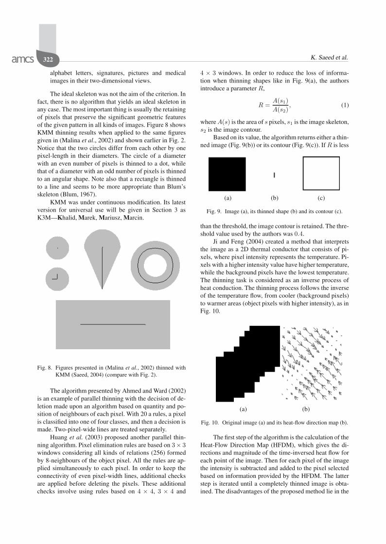
The ideal skeleton was not the aim of the criterion. Infact, there is no algorithm that yields an ideal skeleton inany case. The most important thing is usually the retainingof pixels that preserve the significant geometric featuresof the given pattern in all kinds of images. Figure 8 showsKMM thinning results when applied to the same figuresgiven in (Malina et al., 2002) and shown earlier in Fig. 2.Notice that the two circles differ from each other by onepixel-length in their diameters. The circle of a diameterwith an even number of pixels is thinned to a dot, whilethat of a diameter with an odd number of pixels is thinnedto an angular shape. Note also that a rectangle is thinnedto a line and seems to be more appropriate than Blum’sskeleton (Blum, 1967).
KMM was under continuous modification. Its latestversion for universal use will be given in Section 3 asK3M—Khalid, Marek, Mariusz, Marcin.
Fig. 8. Figures presented in (Malina et al., 2002) thinned withKMM (Saeed, 2004) (compare with Fig. 2).
The algorithm presented by Ahmed and Ward (2002)is an example of parallel thinning with the decision of de-letion made upon an algorithm based on quantity and po-sition of neighbours of each pixel. With 20 a rules, a pixelis classified into one of four classes, and then a decision ismade. Two-pixel-wide lines are treated separately.
Huang et al. (2003) proposed another parallel thin-ning algorithm. Pixel elimination rules are based on 3× 3windows considering all kinds of relations (256) formedby 8-neighbours of the object pixel. All the rules are ap-plied simultaneously to each pixel. In order to keep theconnectivity of even pixel-width lines, additional checksare applied before deleting the pixels. These additionalchecks involve using rules based on 4 × 4, 3 × 4 and
4 × 3 windows. In order to reduce the loss of informa-tion when thinning shapes like in Fig. 9(a), the authorsintroduce a parameter R,
R =A(s1)A(s2)
, (1)
where A(s) is the area of s pixels, s1 is the image skeleton,s2 is the image contour.
Based on its value, the algorithm returns either a thin-ned image (Fig. 9(b)) or its contour (Fig. 9(c)). If R is less
(a) (b) (c)
Fig. 9. Image (a), its thinned shape (b) and its contour (c).
than the threshold, the image contour is retained. The thre-shold value used by the authors was 0.4.
Ji and Feng (2004) created a method that interpretsthe image as a 2D thermal conductor that consists of pi-xels, where pixel intensity represents the temperature. Pi-xels with a higher intensity value have higher temperature,while the background pixels have the lowest temperature.The thinning task is considered as an inverse process ofheat conduction. The thinning process follows the inverseof the temperature flow, from cooler (background pixels)to warmer areas (object pixels with higher intensity), as inFig. 10.
(a) (b)
Fig. 10. Original image (a) and its heat-flow direction map (b).
The first step of the algorithm is the calculation of theHeat-Flow Direction Map (HFDM), which gives the di-rections and magnitude of the time-inversed heat flow foreach point of the image. Then for each pixel of the imagethe intensity is subtracted and added to the pixel selectedbased on information provided by the HFDM. The latterstep is iterated until a completely thinned image is obta-ined. The disadvantages of the proposed method lie in the
K3M: A universal algorithm for image skeletonization and a review of thinning techniques 323
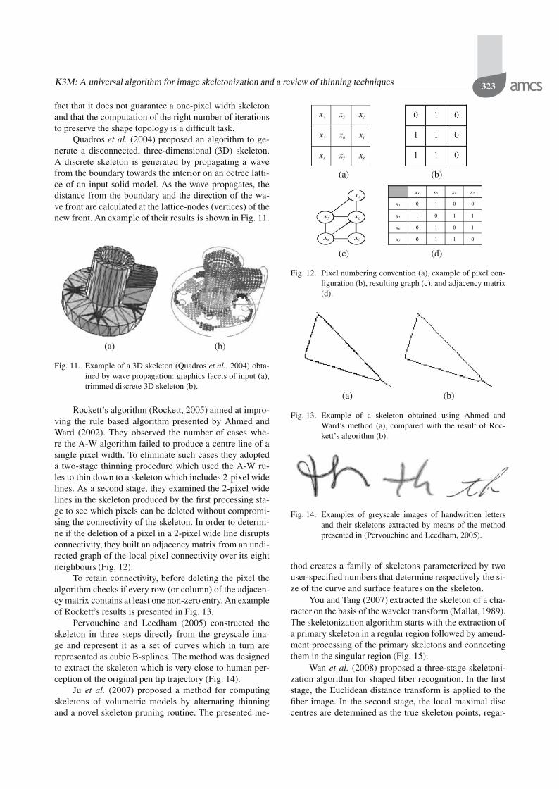
fact that it does not guarantee a one-pixel width skeletonand that the computation of the right number of iterationsto preserve the shape topology is a difficult task.
Quadros et al. (2004) proposed an algorithm to ge-nerate a disconnected, three-dimensional (3D) skeleton.A discrete skeleton is generated by propagating a wavefrom the boundary towards the interior on an octree latti-ce of an input solid model. As the wave propagates, thedistance from the boundary and the direction of the wa-ve front are calculated at the lattice-nodes (vertices) of thenew front. An example of their results is shown in Fig. 11.
(a) (b)
Fig. 11. Example of a 3D skeleton (Quadros et al., 2004) obta-ined by wave propagation: graphics facets of input (a),trimmed discrete 3D skeleton (b).
Rockett’s algorithm (Rockett, 2005) aimed at impro-ving the rule based algorithm presented by Ahmed andWard (2002). They observed the number of cases whe-re the A-W algorithm failed to produce a centre line of asingle pixel width. To eliminate such cases they adopteda two-stage thinning procedure which used the A-W ru-les to thin down to a skeleton which includes 2-pixel widelines. As a second stage, they examined the 2-pixel widelines in the skeleton produced by the first processing sta-ge to see which pixels can be deleted without compromi-sing the connectivity of the skeleton. In order to determi-ne if the deletion of a pixel in a 2-pixel wide line disruptsconnectivity, they built an adjacency matrix from an undi-rected graph of the local pixel connectivity over its eightneighbours (Fig. 12).
To retain connectivity, before deleting the pixel thealgorithm checks if every row (or column) of the adjacen-cy matrix contains at least one non-zero entry. An exampleof Rockett’s results is presented in Fig. 13.
Pervouchine and Leedham (2005) constructed theskeleton in three steps directly from the greyscale ima-ge and represent it as a set of curves which in turn arerepresented as cubic B-splines. The method was designedto extract the skeleton which is very close to human per-ception of the original pen tip trajectory (Fig. 14).
Ju et al. (2007) proposed a method for computingskeletons of volumetric models by alternating thinningand a novel skeleton pruning routine. The presented me-
(a) (b)
(c) (d)
Fig. 12. Pixel numbering convention (a), example of pixel con-figuration (b), resulting graph (c), and adjacency matrix(d).
(a) (b)
Fig. 13. Example of a skeleton obtained using Ahmed andWard’s method (a), compared with the result of Roc-kett’s algorithm (b).
Fig. 14. Examples of greyscale images of handwritten lettersand their skeletons extracted by means of the methodpresented in (Pervouchine and Leedham, 2005).
thod creates a family of skeletons parameterized by twouser-specified numbers that determine respectively the si-ze of the curve and surface features on the skeleton.
You and Tang (2007) extracted the skeleton of a cha-racter on the basis of the wavelet transform (Mallat, 1989).The skeletonization algorithm starts with the extraction ofa primary skeleton in a regular region followed by amend-ment processing of the primary skeletons and connectingthem in the singular region (Fig. 15).
Wan et al. (2008) proposed a three-stage skeletoni-zation algorithm for shaped fiber recognition. In the firststage, the Euclidean distance transform is applied to thefiber image. In the second stage, the local maximal disccentres are determined as the true skeleton points, regar-

324 K. Saeed et al.
(a) (b)
Fig. 15. Examples of images (a) and their thinned versions (b)using the algorithm described in (You and Tang, 2007).
dless of their connectivity. In the last step, a full skeleton isgenerated by linking isolated skeleton points, and pruningspurs arising from edge noise (Fig. 16).
(a) (b)
Fig. 16. Examples of star and trilobal shaped fibres (a) and theirskeletons (b) obtained using the method presented in(Wan et al., 2008).
Table 1 concludes the presentation of selected worksby giving a summary of their most important features.
3. K3M: A modified KMM algorithm
This section presents the K3M (improved and generalizedKMM) thinning algorithm in detail. First, definitions andassumptions are presented, and then a detailed algorithmdescription is introduced with flowcharts and neighbour-hood lookup arrays.
3.1. Assumptions and definitions.
1. According to K3M, the aim of thinning is defined asthe reduction of the number of pixels of an image that
will preserve the structure of the image very well. Asa result, after the transformation, lines that contributeto the letter are of a shape similar to the original andcross in a similar way.
2. The input image is binary, where each pixel is eitheran image pixel (encoded as 1) or a background pi-xel (encoded as 0). Therefore, colour and grey-scaledimages are transformed to binary form.
3. The K3M algorithm is a sequential iterative algori-thm: the iterations are repeated in sequence until nomodification is made to the image during the wholeiteration.
4. Each iteration involves seven phases (numberedfrom 0 to 6). The number of phases is determinedin an empirical way.
5. Pixel neighbours are image pixels that are in the closevicinity of the tested pixel.
6. Border pixels are those image pixels that stick to thebackground (they have no more than seven neighbo-urs). Therefore, they are considered potential candi-dates for deletion.
7. Thinning decisions are made for border pixels, basedon 3 × 3 neighbourhood templates of the tested pi-xel. The 3×3 neighbourhood was chosen because ofits large size capable to provide satisfactory thinningresults. Larger neighbourhoods, however, would de-mand more computational complexity and executiontime.
8. The thinning decision is either to delete the pixel(change an image pixel into a background one) orto retain it (the image pixel is not changed). Thepossible neighbourhood configurations are encodedusing values in the range [0, 255] named neighbourweights. The encoded neighbourhood configurationsrepresented by neighbour weights are individual foreach phase and are stored in lookup arrays.
9. After the iterations are finished, a supplemental pro-cedure is required to produce a one-pixel width ske-leton. This is because the iterative part of the algori-thm is aimed at producing a fine skeleton and hencethe algorithm is unable to produce a one-pixel widthskeleton.
3.2. Algorithm description. K3M consists of an ite-rative part of seven phases and a single additional phaseat the end, which is responsible for producing a one pixel-width skeleton. The overview of the algorithm is presentedin Fig. 17.

K3M: A universal algorithm for image skeletonization and a review of thinning techniques 325
Table 1. Basic algorithms of thinning.Year Author Type Remarks
1966 Rutovitz (1966) parallel, iterative, not dividedinto subcycles
can result in excessive erosion, does not reduce diagonallines to a unit pixel width, the skeleton does not lie cen-trally
1967 Blum (1967) medial axis transformation, no-niterative
1969 Hilditch (1969) sequential maintain connectivity, preserve two-pixel wide lines1975 Rosenfeld (1975) parallel solves the problem of erosion in the thinning of diagonal
lines1978 Arcelli and di Baja (1978) parallel does not remove all deletable pixels1979 Dyer and Rosenfeld (1979) interative directly thins gray-scale images1980 Pavlidis (1980) sequential, combined sequen-
tial and paralleldoes not result in a one-pixel-wide skeleton
1981 Arcelli (1981) sequential uses contour tracing to reduce computational time1983 Favre and Keller (1983) one-subcycle parallel1985 Ammann and Sartori-Angus (1985) sequential uses image compression before thinning to reduce compu-
tational time1987 Chin et al. (1987) 1-subcycle, parallel skeleton biased in line junctions1988 Baruch (1988) noniterative produces skeleton in one pass, by line following1989 Guo and Hall (1989) iterative, 2-subcycles does not give a one-pixel-wide skeleton1989 Chen and Hsu (1989a; 1989b) 1-subcycle, parallel bias-reduced skeletons1994 Parker et al. (1994) force-based acquires a skeleton by using force vectors1996 Zhang and Wang (1996) 2-subcycles, parallel preserves connectivity, produces one-pixel-wide skeletons1998 Altuwaijri and Bayoumi (1998) neural networks based redundant loops removal—disadvantage in certain alpha-
bets2000 Andreadis et al. (2000) interative obtains skeletons from color images2001 KMM (Saeed et al., 2001) sequential, iterative maintain connectivity, bias-reduced skeletons2002 Ahmed and Ward (2002) parallel fails to produce a 1-pixel width line in some patterns2003 Huang et al. (2003) parallel2004 Ji and Feng (2004) noniterative does not guarantees one-pixel width skeleton, problems
with choosing the right number of iterations2004 Quadros et al. (2004) 3-dimensional uses wave propagating from the boundary towards the in-
terior2005 Rockett (2005) parallel produces one-pixel-wide skeletons, uses a two-stage thin-
ning procedure2005 Pervouchine and Leeedham (2005) gray-scale image thinning represents a skeleton as cubic B-splines2007 Ju et al. (2007) creates a family of skeletons with various sizes of the cu-
rve and surface features2007 You and Tang (2007) wavelet based extracted skeleton is centered inside the underlying stroke2008 Wan et al. (2008) distance map based three-stage skeletonization algorithm for shaped fiber re-
cognition
Iterative part overview
• Phase 0: Mark borders for examination.
• Phase 1: Delete the borders that have 3 neighbourssticking each other.
• Phase 2: Delete the borders that have 3 or 4 neighbo-urs sticking each other.
• Phase 3: Delete the borders that have 3, 4 or 5 neigh-bours sticking each other.
• Phase 4: Delete the borders that have 3, 4, 5 or 6neighbours sticking each other.
• Phase 5: Delete the borders that have 3, 4, 5, 6 or 7neighbours sticking each other.
• Phase 6: Unmark the remaining borders.
• Decision: If any modification was made during thecurrent iteration, return to Phase 0.
Thinning to a one-pixel width skeleton. This phaseaims at producing skeletons consisting of pixels with onlytwo neighbours unless located at a junction. This is a si-gnificant advantage of a one-pixel width skeleton as it po-tentially allows producing structural graphs of the exami-ned image.
The essential property of each pixel, which is usedfor quick determination of its neighbourhood configura-tion, is the neighbour weight. It is an 8-bit number, wheresubsequent bit values correspond to neighbours, startingfrom the pixel above and going clockwise. It is calculatedwith the use of the neighbourhood bit values matrix (3),as in (2), where w(x, y) is the neighbour weight of pixel(x, y) and img(x, y) is the binary value of the image pixelat coordinates (x, y).

326 K. Saeed et al.
Fig. 17. K3M algorithm simplified flowchart.
Neighbour weight calculation
w(x, y) =1∑
i=−1
1∑
j=−1
N(i + 1, j + 1) · img(x + i, y + j).
(2)
Neighbourhood bit values matrix
N =
⎡
⎣128 1 264 0 432 16 8
⎤
⎦ . (3)
Figure 18 presents the flowchart of Phase 0, aimed atmarking borders (pixels that are candidates for deletion).
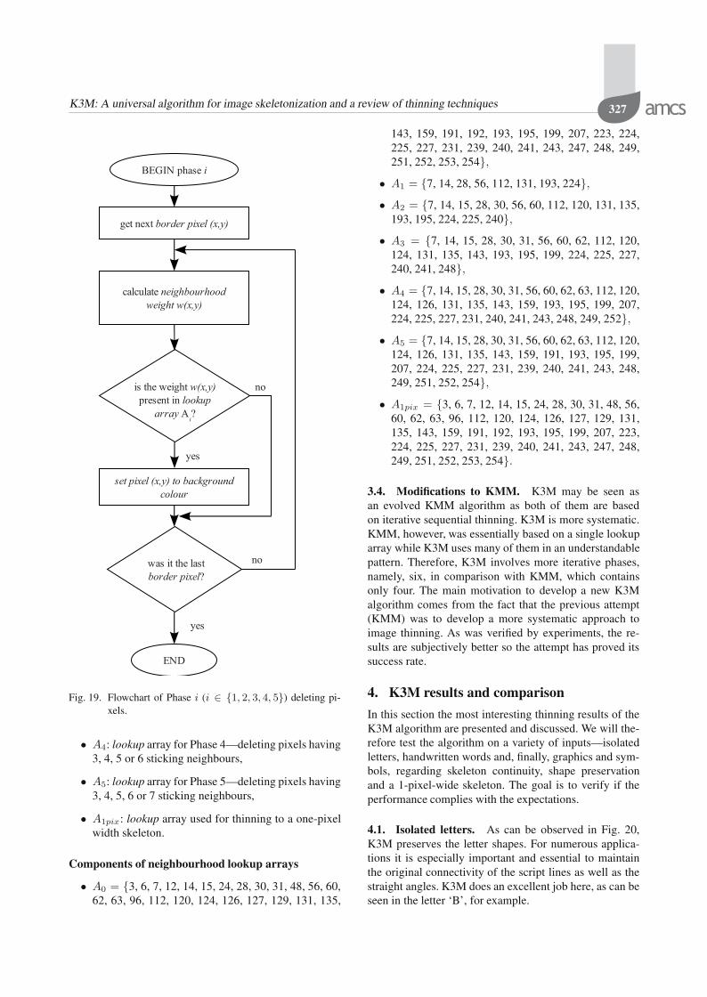
The iterative phases 1 to 5 are very similar to eachother and aim at deleting pixels with a growing number ofsticking neighbours. The phases may be presented usinga common flowchart with parameter i that changes from1 to 5 (see Fig. 19) and determines the employed lookuparray Ai.
3.3. Neighbourhood lookup arrays. In this sectionsome specific neighbourhood lookup arrays are given.
!"!#"
" "
$
%
$ "
Fig. 18. Flowchart of phase 0—marking borders.
They serve for marking borders and determining thinningdecisions. The components of arrays Ai (Phases 1 to 5)follow the rules mentioned in the algorithm descriptionconcerning the number of neighbours. The contents of ar-ray A1pix (thinning to a one-pixel width skeleton) was de-termined on the basis of several experiments and the au-thors’ original KMM algorithm (Saeed et al., 2001).
List of neighbourhood lookup arrays
• A0: lookup array for Phase 0—marking borders,
• A1: lookup array for Phase 1—deleting pixels having3 sticking neighbours,
• A2: lookup array for Phase 2—deleting pixels having3 or 4 sticking neighbours,
• A3: lookup array for Phase 3—deleting pixels having3, 4 or 5 sticking neighbours,
K3M: A universal algorithm for image skeletonization and a review of thinning techniques 327
!"!#"
$
%
&
$ "
Fig. 19. Flowchart of Phase i (i ∈ 1, 2, 3, 4, 5) deleting pi-xels.
• A4: lookup array for Phase 4—deleting pixels having3, 4, 5 or 6 sticking neighbours,
• A5: lookup array for Phase 5—deleting pixels having3, 4, 5, 6 or 7 sticking neighbours,
• A1pix: lookup array used for thinning to a one-pixelwidth skeleton.
Components of neighbourhood lookup arrays
• A0 = 3, 6, 7, 12, 14, 15, 24, 28, 30, 31, 48, 56, 60,62, 63, 96, 112, 120, 124, 126, 127, 129, 131, 135,
143, 159, 191, 192, 193, 195, 199, 207, 223, 224,225, 227, 231, 239, 240, 241, 243, 247, 248, 249,251, 252, 253, 254,
• A1 = 7, 14, 28, 56, 112, 131, 193, 224,• A2 = 7, 14, 15, 28, 30, 56, 60, 112, 120, 131, 135,
193, 195, 224, 225, 240,• A3 = 7, 14, 15, 28, 30, 31, 56, 60, 62, 112, 120,
124, 131, 135, 143, 193, 195, 199, 224, 225, 227,240, 241, 248,
• A4 = 7, 14, 15, 28, 30, 31, 56, 60, 62, 63, 112, 120,124, 126, 131, 135, 143, 159, 193, 195, 199, 207,224, 225, 227, 231, 240, 241, 243, 248, 249, 252,
• A5 = 7, 14, 15, 28, 30, 31, 56, 60, 62, 63, 112, 120,124, 126, 131, 135, 143, 159, 191, 193, 195, 199,207, 224, 225, 227, 231, 239, 240, 241, 243, 248,249, 251, 252, 254,
• A1pix = 3, 6, 7, 12, 14, 15, 24, 28, 30, 31, 48, 56,60, 62, 63, 96, 112, 120, 124, 126, 127, 129, 131,135, 143, 159, 191, 192, 193, 195, 199, 207, 223,224, 225, 227, 231, 239, 240, 241, 243, 247, 248,249, 251, 252, 253, 254.
3.4. Modifications to KMM. K3M may be seen asan evolved KMM algorithm as both of them are basedon iterative sequential thinning. K3M is more systematic.KMM, however, was essentially based on a single lookuparray while K3M uses many of them in an understandablepattern. Therefore, K3M involves more iterative phases,namely, six, in comparison with KMM, which containsonly four. The main motivation to develop a new K3Malgorithm comes from the fact that the previous attempt(KMM) was to develop a more systematic approach toimage thinning. As was verified by experiments, the re-sults are subjectively better so the attempt has proved itssuccess rate.
4. K3M results and comparison
In this section the most interesting thinning results of theK3M algorithm are presented and discussed. We will the-refore test the algorithm on a variety of inputs—isolatedletters, handwritten words and, finally, graphics and sym-bols, regarding skeleton continuity, shape preservationand a 1-pixel-wide skeleton. The goal is to verify if theperformance complies with the expectations.
4.1. Isolated letters. As can be observed in Fig. 20,K3M preserves the letter shapes. For numerous applica-tions it is especially important and essential to maintainthe original connectivity of the script lines as well as thestraight angles. K3M does an excellent job here, as can beseen in the letter ‘B’, for example.

328 K. Saeed et al.
Fig. 20. Thinning isolated letters with K3M.
4.2. Handwritten words. In most cases printed wordsare thinned (with some exception in the case of bad qualitytexts) in the same way as several isolated letters. Handw-ritten words, however, are interesting as they contain oneor more connections between individual letters, extra lo-ops, and irregularities, which is worth studying.
Fig. 21. Handwritten words thinned with K3M.
As seen in Fig. 21, the overall shapes of the examinedwords are well preserved. However, for possibly closed-
loops letters, like the second ‘e’ in the word ‘seven’, itis obvious that some information is lost. It is impossibleto avoid such problems without additional steps to createa real loop from such a letter. Irregular dots are transferredto short lines rather than to real dots, which is a commontrait for most thinning algorithms.
4.3. Graphical symbols. In thinning graphical sym-bols (Fig. 22) and graphic-alike alphabets (Fig. 23), it isespecially important to keep the right angles and intercon-nections close in terms of the shape to the original pictu-re. One can see that these aspects are well managed by theK3M algorithm. However, occasional deformations of ori-ginally straight diagonally placed lines can be observed.
(a) (b)
Fig. 22. Thinning graphical symbols with K3M: original ima-ges (a), their thinned shapes (b).
Fig. 23. Results of thinning a Japanese symbol with K3M.
4.4. Comparison of results between K3M and otheralgorithms. Table 2 shows the results of thinning whenusing the K3M approach in comparison with some of theabove-mentioned algorithms.
Table 3, however, presents a comparison betweenK3M and other algorithms considering several importantaspects, like the output width, angles preservation and to-pology preservation.
4.5. Advantages and drawbacks of K3M. K3M hasthe following feasible advantages:

K3M: A universal algorithm for image skeletonization and a review of thinning techniques 329
Table 2. Results of thinning by Guo and Hall’s, Zhang’s, A-W, KMM and K3M algorithms.Image
Method
Guo and Hall’s (Guo and Hall, 1992)
Zhang’s (Zhang and Wang, 1996)
A-W (Ahmed and Ward, 2002)
KMM (Saeed et al., 2001)
K3M
Table 3. Comparison of results: K3M and others.
AlgorithmGuo and
Hall (1992)
Zhang andWang(1996)
Ahmed andWard (2002)
KMM(Saeed
et al., 2001)K3M
1-pixel wide – + – + +bias-reduced skeleton (preserves right angles) – – – – +preserves topology (no disappearances) – + – + +
1. The algorithm preserves right angles at the lines in-terconnections, which result in better correspondencebetween the original and the modified image.
2. It produces a one-pixel-wide skeleton.
3. The iterative phases are clearly aimed at deleting pi-xels in a specific neighbourhood, therefore a generalidea of this thinning method is easily found.
4. The universality of the algorithm allows wide and di-versified applications.
Although the K3M algorithm has successfully pro-ved its universal performance over many other algorithms,it is intrinsically iterative in nature, and hence it requiresmore computing power than other, non-iterative algori-thms. Moreover, each iteration contains seven sequentialphases. This increases the computational complexity andmakes the parallelization attempts difficult.
Despite the fact that these drawbacks do not affectthe shape preservation, the authors are currently workingon reducing the algorithm complexity and computationalpower requirements. The new results will be the matter ofa future publication after proving their validity.
5. Parallelizing sequential algorithms
Non-one-pass iterative thinning algorithms (sequential al-gorithms with one or more subcycles) are not intrinsical-ly suitable for parallel processing. Therefore, they tend tohave difficulties with successful utilisation of modern pa-rallel data processing techniques like multi-core proces-sors or processor grids (hardware or network implemen-ted). With the growing of the usage and popularity of pa-rallel processing hardware and its techniques, it is basicto develop solutions that would allow such algorithms toprofit from the use of multi-processors.

330 K. Saeed et al.
In Fig. 24 one can see scanline-type sequential pro-cessing, where rows are processed sequentially. For eachpixel, a decision is made based on the state of the neigh-bours.
Fig. 24. Sequential scanline-type processing.
The steps of the iterative thinning algorithm are re-peated several times in their consecutive iterations. Eachprocessing step may contain several sub-cycles with ope-rations such as flagging some pixels (for example, ascandidates for deletion or as non-deletable pixels). Fur-thermore, sub-cycles perform their operations depending,among other things, on that information. The final deci-sion depends on the flags of neighbours set in the previoussubcycles, making the algorithm impossible to perform ina parallel way as there exists information dependence be-tween neighbouring pixels (information on the actual stateof neighbours is required at the specified subcycle).
The information dependence area grows with eachsubcycle included in the iteration, as the state of neighbo-urs depends on the states of their neighbours, and so on.The growth of the effective neighbourhood is presented inFig. 25.
Fig. 25. Dependence area growth due to information dependen-ce.
There may be several solutions that allow parallelprocessing of such problematic thinning algorithms:
• Modification of the thinning algorithm to diminish oreliminate subcycles. In the case of elimination, it le-ads to the possibility of fully parallel processing. Inthe case of decreasing the number of subcycles, it di-minishes the information dependence area.
• Division of the image in such a way that information
dependence is non-existent or irrelevant. This is notalways possible.
• Division with overlapping regions—regular divisionwhile providing indispensable information (informa-tion dependence areas from the area of division) foreach parallel processor.
5.1. Division with overlapping regions. In the divi-sion process, the image is divided into some overlappingparts to be processed in parallel. These parts are calledregions. Figure 26 shows how an image space is dividedinto two regions P1 and P2. Figure 27, however, showshow they are overlapped.
P1
P2
Fig. 26. Parallel scanline-type processing on different image re-gions P1 and P2.
Obviously, in the region edge each pixel has its de-finite number of neighbours. We can then deduce that theneighbouring pixel weights have a basic role in the de-cision taking process during the thinning procedure. Theedge pixels of P1 in the crossing border between P1 andP2 actually stick the neighbours of other pixels belongingto P2. That is why the edge pixels from two regions sha-re neighbours and hence some useful data are available toboth parts.
Fig. 27. Pixel in the region edge.
In most algorithms (including KMM and K3M) the

K3M: A universal algorithm for image skeletonization and a review of thinning techniques 331
neighborhood is of a 3 × 3 character, but the approach isalso valid for 3×4 or 5×5 neighborhood basis algorithms.
The overlapping area serves as the container of infor-mation needed for neighbourhood checking. The width ofthe region depends on the number of subcycles in the thin-ning algorithm and the requested number of independentparallel cycles of the algorithm. Such a configuration maybe presented as read/write privileges of processes (as seenin Fig. 28) assuming that the processes operate on a sharedmemory.
P2
P1 read, write
P2 read only
P1 read only
P2 read, write
P1
Fig. 28. Overlapping regions.
Pseudocode of the non-parallelized thinning algorithm
while not thinned doforeach pixel in image
check pixel neighboursdo thinning routines
end foreachend do
Pseudocode of the parallelized thinning algorithm
iteration := 1while not thinned doforeach pixel in image
if neighbour in border band thenwhile neighbour.iteration < iteration-1 do
wait for synchronizationend while
end ifcheck pixel neighboursdo thinning routinesif pixel in border band then
send synchronization infoend if
end foreachiteration := iteration + 1
end do
5.2. Prediction of the neighbouring processor deci-sion. In some cases it is possible to predict the decisionthat a neighbouring processor should make. In particular,if a pixel in the border area is “white,” no change can bemade in conventional thinning (with a possible exceptionof thinning algorithms that perform thinned shapes smo-othing). That may particularly simplify the synchroniza-tion task as presented above.
6. Conclusions and future work
The first aspect presented in the paper was the survey pre-sentation of the state of the art in the thinning area. A verylarge number of algorithms in this field have been propo-sed and due to the complicated nature of skeletonizationit is often unclear how the approaches are related to eachother in terms of processing quality and the general idea.A number of important works ranging from the earliestto the latest publications on thinning were discussed andcompared. Short summaries with the available results ofthose algorithms were also presented. For the sake of ge-neral comparison, essential and basic traits of the algori-thms were shown. The main points of view were the ty-pe of methodology used and the parallelization possibility(intrinsic or secondary) with final general remarks on theobtained results or the dedicated application of the studiedalgorithm. The survey is considered a background for theauthors’ proposal of the thinning algorithm named K3M.
The second important aspect of the paper is the pre-sentation of the authors’ algorithm evolved from the ori-ginal KMM algorithm. The proposed algorithm introdu-ces its advantages in terms of several important characte-ristics: thinning quality, a large range of possible applica-tions and the clarity of processing stages. The examplesshown in Section 4 for isolated letters, words and graphi-cal symbols demonstrate the processing quality of K3M.The examined examples showed that the K3M algorithmpresents constant quality for printed words, handwrittenscripts, numbers and characters of both Latin and non-Latin alphabets. This fact proves the universal characterof the K3M algorithm compared with other algorithmsknown to the authors, which can be considered the mostimportant advantage.
The next task, which has been proved to be true inpractical applications, is that the idea of the algorithm isclear and simple to follow. This was mainly demonstratedin the detailed description in Section 3. The clarity andsimple nature of the algorithm make it easy to study anduse, which is significant when compared with other, oftenempirically obtained, algorithms.
The last important aspect shown and discussed in thepaper regards parallelization issues for sequential thinningalgorithms. This matter was considered in Section 5 andcould certainly benefit in improving many sequential ite-rative thinning algorithms. It is particularly useful in thecontext of the recent popularity of parallel processing har-dware and software techniques.
Future work is mainly aimed at two directions: thefirst is related to fine-tuning of the algorithm in order toeliminate the slight deformation of some lines currentlyoccurring. The introduced changes, however, should nothassle the universality of the applications of the algori-thm. The second development direction is the reduction ofthe number of phases in the iterative part of the K3M al-

332 K. Saeed et al.
gorithm. That would result in lowering the computationaleffort as well as improving the parallelization possibilityof the algorithm.
Acknowledgment
This work is supported by the Rector of Białystok Tech-nical University (grant no. W/WI/10/07).
The authors are indebted to the anonymous refereesfor their constructive and valuable comments, and for theirextremely helpful suggestions that improved the quality ofthe presented work.
ReferencesAhmed, M. and Ward, R. (2002). A rotation invariant rule-
based thinning algorithm for character recognition, IEEETransactions on Pattern Analysis and Machine Intelligen-ce 24(12): 1672–1678.
Altuwaijri, M.M. and Bayoumi, M.A. (1998). A thinning algori-thm for arabic characters using art2 neural network, IEEETransactions on Circuits and Systems II: Analog and Digi-tal Signal Processing 45(2): 260–264.
Ammann, C.J. and Sartori-Angus, A.G. (1985). Fast thinningalgorithm for binary images, Image Vision and Computing3(2): 71–79.
Andreadis, I., Vardavoulia, M., Louverdis, G. and Papamarkos,N. (2000). Colour image skeletonisation, Proceedings ofthe 10th European Signal Processing Conference, Tampe-re, Finland, Vol. 4, pp. 2389–2392.
Arcelli, C. (1981). Pattern thinning by contour tracing, Compu-ter Graphics Image Processing 17(2): 130–144.
Arcelli, C. and di Baja, G.S. (1978). On the sequential appro-ach to medial line transformation, IEEE Transactions onSystems, Man and Cybernetics 8(2): 139–144.
Arcelli, C. and di Baja, G.S. (1981). A thinning algorithm ba-sed on prominence detection, Pattern Recognition 13(3):225–235.
Arcelli, C. and di Baja, G.S. (1987). A contour characterizationfor multiply connected figures, Pattern Recognition Letters6(4): 245–249.
Arcelli, C. and di Baja, G.S. (1989). A one-pass two-operationprocess to detect the skeletal pixels on the 4-distance trans-form, IEEE Transactions on Pattern Analysis and MachineIntelligence 11(4): 411–414.
Baruch, O. (1988). Line thinning by line following, Pattern Re-cognition Letters 8(4): 271–276.
Blum, H. (1967). A transformation for extracting new descrip-tors of shape, in W.W. Dunn (Ed.), Models for the Percep-tion of Speech and Visual Form, MIT Press, Cambridge,MA, pp. 362–380.
Chen, Y.-S. (1996). The use of hidden deletable pixel detec-tion to obtain bias-reduced skeletons in parallel thinning,ICPR ’96: Proceedings of the 13th International Con-ference on Pattern Recognition, Washington, DC, USA,pp. 91–95.
Chen, Y.-S. and Hsu, W.-H. (1988). A modified fast parallelalgorithm for thinning digital patterns, Pattern RecognitionLetters 7(2): 99–106.
Chen, Y.-S. and Hsu, W.-H. (1989a). A 1-subcycle parallel thin-ning algorithm for producing perfect 8-curves and obta-ining isotropic skeleton of an l-shape pattern, Proceedingsof the International Conference on Computer Vision andPattern Recognition, San Diego, CA, USA, pp. 208–215.
Chen, Y.-S. and Hsu, W.-H. (1989b). A systematic approach fordesigning 2-subcycle and pseudo 1-subcycle parallel thin-ning algorithms, Pattern Recognition 22(3): 267–282.
Chen, Y.-S. and Hsu, W.-H. (1990). A comparison of someone-pass parallel thinnings, Pattern Recognition Letters11(1): 35–41.
Chin, R.T., Wan, H.-K., Stover, D.L. and Iverson, R. D. (1987).A one-pass thinning algorithm and its parallel implemen-tation, Computer Vision, Graphics, and Image Processing40(1): 30–40.
Dinnen, G. (1955). Programming pattern recognition, Proce-edings of the Western Joint Computer Conference, Los An-geles, CA, USA, pp. 94–100.
Dyer, C. and Rosenfeld, A. (1979). Thinning algorithms forgray-scale pictures, IEEE Transactions on Pattern Analy-sis and Machine Intelligence 1(1): 88–89.
Favre, A. and Keller, H. (1983). Parallel syntactic thinning byrecoding of binary pictures, Computer Vision, Graphics,and Image Processing 23(1): 99–112.
Gonzalez, R.C. and Woods, R.E. (2007). Digital Image Proces-sing, 3rd Edition, Prentice Hall, Upper Saddle River, NJ.
Guo, Z. and Hall, R.W. (1989). Parallel thinning with two-subiteration algorithms, Communications of the ACM32(3): 359–373.
Guo, Z. and Hall, R.W. (1992). Fast fully parallel thinning algo-rithms, CVGIP: Image Understanding 55(3): 317–328.
Hilditch, C.J. (1968). An application of graph theory in patternrecognition, Machine Intelligence 3: 325–347.
Hilditch, C.J. (1969). Linear skeletons from square cupboards,Machine Intelligence 4: 403–420.
Huang, L., Wan, G. and Liu, C. (2003). An improved paral-lel thinning algorithm, ICDAR ’03: Proceedings of the Se-venth International Conference on Document Analysis andRecognition, Washington, DC, USA, pp. 780–783.
Jaisimha, M.Y., Haralick, R.M. and Dori, D. (1994). Quantita-tive performance evaluation of thinning algorithms undernoisy conditions, Proceedings of the IEEE Conference onComputer Vision and Pattern Recognition (CVPR), Seattle,WA, USA, pp. 678–683.
Jang, B.K. and Chin, R.T. (1992). One-pass parallel thinning:Analysis, properties and quantitative evaluation, Trans-actions on Pattern Analysis and Machine Intelligence14(11): 1129–1140.
Ji, X. and Feng, J. (2004). A new approach to thinning ba-sed on time-reversed heat conduction model, InternationalConference on Image Processing (ICIP), Singapore, Vol. 1,pp. 653–656.

K3M: A universal algorithm for image skeletonization and a review of thinning techniques 333
Ju, T., Baker, M.L. and Chiu, W. (2007). Computing a familyof skeletons of volumetric models for shape description,Computer-Aided Design 39(5): 352–360.
Kirsch, R.A., Cahn, L., Ray, C. and Urban, G.H. (1958). Expe-riments in processing pictorial information with a digitalcomputer, IRE-ACM-AIEE ’57 (Eastern): Papers and Di-scussions Presented at the December 9-13, 1957, EasternJoint Computer Conference: Computers with Deadlines toMeet, New York, NY, USA, pp. 221–229.
Klette, R. and Rosenfeld, A. (2004). Digital Geometry: Geo-metric Methods for Digital Image Analysis, Morgan Kauf-mann, San Francisco, CA.
Lam, L., Lee, S.-W. and Suen, C.Y. (1992). Thinningmethodologies—A comprehensive survey, IEEE Trans-actions on Pattern Analysis and Machine Intelligence14(9): 869–885.
Lee, S.-W., Lam, L. and Suen, C. Y. (1991). Performance evalu-ation of skeletonizing algorithms for document image pro-cessing, Proceedings of the First International Conferenceon Document Analysis and Recognition, Saint-Malo, Fran-ce, pp. 260–271.
Malina, W., Ablemeyko, S. and Pawlak, W. (2002). Funda-mentals of Digital Image Processing, Akademicka OficynaWydawnicza EXIT, Warsaw, (in Polish).
Mallat, S. (1989). A theory for multiresolution signal decompo-sition: The wavelet representation, IEEE Transactions onPattern Analysis and Machine Intelligence 11(7): 674–693.
Parker, J., Jennings, C. and Molaro, D. (1994). A force-basedthinning strategy with sub-pixel precision, Vision InterfaceConference, Banff, Alberta, Canada.
Pavlidis, T. (1980). A thinning algorithm for discrete binaryimages, Computer Graphics Image Processing 13(2): 142–157.
Pavlidis, T. (1981). A flexible parallel thinning algorithm, Proce-edings of the International Conference on Pattern Recogni-tion and Image Processing, Dallas, TX, USA, pp. 162–167.
Pavlidis, T. (1982a). Algorithms for Graphics and Image Proces-sing, Springer, Computer Science Press, Rockville, MD.
Pavlidis, T. (1982b). An asynchronous thinning algorithm, Com-puter Graphics Image Processing 20(2): 133–157.
Pervouchine, V. and Leedham, G. (2005). Document exami-ner feature extraction: Thinned vs. skeletonised handwri-ting images, Proceedings of the IEEE Region 10 TechnicalConference (TENCON05), Melbourne, Australia, pp. 1–6.
Quadros, W. R., Shimada, K. and Owen, S. J. (2004). 3d discreteskeleton generation by wave propagation on pr-octree forfinite element mesh sizing, SM ’04: Proceedings of theNinth ACM Symposium on Solid Modeling and Applica-tions, Aire-la-Ville, Switzerland, pp. 327–332.
Rockett, P. I. (2005). An improved rotation-invariant thinningalgorithm, IEEE Transactions on Pattern Analysis and Ma-chine Intelligence 27(10): 1671–1674.
Rosenfeld, A. (1975). A characterization of parallel thinningalgorithms, Information and Control 29(3): 286–291,http://theory.lcs.mit.edu/~iandc/ic75.html
Rutovitz, D. (1966). Pattern recognition, Journal of Royal Stati-stical Society 129(4): 504–530.
Saeed, K. (2001). Text and image processing: Non-interruptedskeletonization, Proceedings of the 1st InternationalIEEE Conference on Circuits, Systems, Comunications andComputers—IEEE-CSCC’01, Crete, Greece, Advances inScientific Computing, Computational Intelligence and Ap-plications, World Scientific Engineering Society Press,pp. 350–354.
Saeed, K. (2004). Image Analysis for Object Recognition, Bia-łystok Technical University Press, Białystok.
Saeed, K. and Niedzielski, R. (1999). Experiments on thinningof cursive-style alphabets, International Conference on In-formation Technologies for Education, Science and Busi-ness ITESB’99, Minsk, Belarus, pp. 45–49.
Saeed, K., Rybnik, M. and Tabedzki, M. (2001). Implementationand advanced results on the non-interrupted skeletoniza-tion algorithm, in W. Skarbek (Ed.) Computer Analysis ofImages and Patterns, Lecture Notes in Computer Science,Vol. 2124, Springer-Verlag, Heidelberg, pp. 601–609.
Wan, Y., Yao, L., Xu, B. and Zeng, P. (2008). A distance mapbased skeletonization algorithm and its application in fiberrecognition, International Conference on Audio, Languageand Image Processing, Shanghai, China, pp. 1769–1774.
You, X. and Tang, Y. Y. (2007). Wavelet-based approach to cha-racter skeleton, IEEE Transactions on Image Processing16(5): 1220–1231.
Zhang, Y. Y. and Wang, P. P. (1996). A parallel thinning algo-rithm with two-subiteration that generates one-pixel-wideskeletons, International Conference on Pattern Recogni-tion, Vienna, Austria, Vol. 4, pp. 457–461.
Khalid Saeed received the B.Sc. degree in elec-trical and electronic engineering in 1976 fromBaghdad University, the M.Sc. (electronics) andPh.D. (telecommunications) degrees from theWrocław University of Technology, Poland, in1978 and 1981, respectively. He received hisD.Sc. degree (habilitation) in computer sciencefrom the Polish Academy of Sciences in Warsawin 2007. From 1992 to 2008 he was with Biały-stok Technical University. Since 2008 he has be-
en a professor of computer science at the AGH University of Science andTechnology in Poland. He has published more than 120 works, about 20edited books, and seven text and reference books. His areas of interestare image analysis and processing, biometrics and computer informationsystems.

334 K. Saeed et al.
Marek Tabedzki received his M.Sc. degree incomputer science from Białystok Technical Uni-versity (Poland) in 2001. He is presently withthe same university, at the Faculty of ComputerScience. His research interests include informa-tion processing systems, particularly digital ima-ge processing and pattern recognition.
Mariusz Rybnik received his M.Sc. degree incomputer science from Białystok Technical Uni-versity (Poland) in 2001, and the Ph.D. degreein engineering in biology and medicine from theUniversity of Paris XII—Val de Marne (France)in 2004. He is currently an assistant professor atthe Faculty of Mathematics and Computer Scien-ce of the University of Białystok. His researchinterests include image processing, pattern reco-gnition, biometrics and artificial intelligence.
Marcin Adamski received his M.Sc. degreein computer science from Białystok TechnicalUniversity (Poland) in 2001, where he curren-tly works at the Faculty of Computer Science.His research interests concern image processingand image recognition methods, and their appli-cations in biometric systems.
Appendix
Pseudocodes of the implemented computer programs
creating N-lookup arrays
alternate to weight calculationfunction lookup(N:integer) : boolean
vector = [pixel.N, pixel.NE, pixel.E,pixel.SE, pixel.S, pixel.SW,pixel.W, pixel.NW]
changes := 0for i := 1 to 7
if vector[i] <> vector[i+1] thenchanges := changes + 1
end ifend forif changes <= 2 then
ones := 1for i := 1 to 8
if vector[i] = 1 thenones := ones + 1
end ifend forif ones = N then
return trueend if
end ifreturn false
end function
pixel.N - north neighbour of actual pixelpixel.NE - northeast neighbour of actual pixeland so on...
param N - number of sticking neighbours needed
classic 1-stage
mark image pixels as 1mark background pixels as 0repeat
thinned = truefor each pixel in image
if pixel = 1 thenif (pixel.N mod 2 = 0) or
(pixel.S mod 2 = 0) or(pixel.W mod 2 = 0) or(pixel.E mod 2 = 0) thenpixel := 3
end ifend if
end forfor each pixel in image
if pixel = 3 then DLA - deletion lookup array if weight(pixel) in DLA then
pixel := 0thinned = false
elsepixel := 3
end ifend if
end forfor each pixel in image
if pixel = 3 thenpixel := 1
end ifend for
until thinnedmark even pixels as backgroundmark odd pixels as image
neighbour weight calculation
function weight(pixel) : integerreturn 1*(pixel.N mod 2) + 2*(pixel.NE mod 2)+
64*(pixel.W mod 2) + 4*(pixel.E mod 2)+32*(pixel.SW mod 2) + 16*(pixel.S mod 2)+8*(pixel.SE mod 2) + 128*(pixel.NW mod 2)
end function
single-for 1-stage
mark image pixels as 1mark background pixels as 0phase := 1repeat
thinned = truefor each pixel p in image
if p mod 2 = 1 then checking if border pixel if (p.N <> 2*phase and p.N mod 2 = 0) or
(p.S <> 2*phase and p.S mod 2 = 0) or(p.W <> 2*phase and p.W mod 2 = 0) or(p.E <> 2*phase and p.E mod 2 = 0) then DLA - deletion lookup array if weight(p) in DLA then
p := 2 * phasethinned = false
elsep := 2 * phase + 1
end ifend if
end if

K3M: A universal algorithm for image skeletonization and a review of thinning techniques 335
end forphase := phase + 1
until thinnedmark even pixels as backgroundmark odd pixels as image
Received: 14 June 2009Revised: 18 October 2009