K3502 - Quasar Electronics · K3502 H3502IP-2 Detects objects u sing ultrasonic waes ULTRASONIC...
16
K3502 H3502IP-2 Detects objects using ultrasonic waves ULTRASONIC RADAR
Transcript of K3502 - Quasar Electronics · K3502 H3502IP-2 Detects objects u sing ultrasonic waes ULTRASONIC...
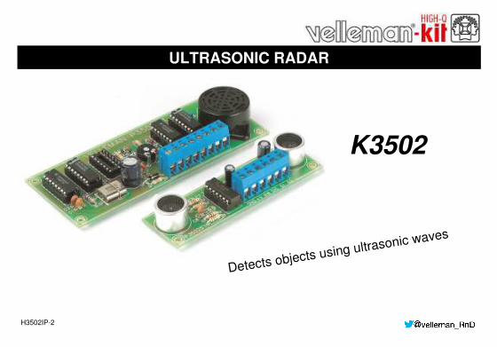
K3502
H3502IP-2
Detects objects using ultrasonic waves
ULTRASONIC RADAR

2
Specifications: Detection range : 5cm - 1,5m (adjustable) Detection angle : 5° Transmitter frequency : 40KHz. Sample frequency : 26Hz. Power supply : 10 - 15VDC / 16mA max. Dimensions :
Sensor PCB : 28 x 95mm / 1,1 x 3,8” Base PCB : 48 x 125mm / 1,9 x 5”
Features & Specifications
Detects objects using ultrasonic waves. When the preset minimum distance is crossed, an audible signal is generated

3
Assembly hints
1. Assembly (Skipping this can lead to troubles ! ) Ok, so we have your attention. These hints will help you to make this project successful. Read them carefully. 1.1 Make sure you have the right tools: A good quality soldering iron (25-40W) with a small tip. Wipe it often on a wet sponge or cloth, to keep it clean; then apply solder to the tip, to give it a wet look. This is called ‘thinning’ and will protect the tip,
and enables you to make good connections. When solder rolls off the tip, it needs cleaning. Thin raisin-core solder. Do not use any flux or grease. A diagonal cutter to trim excess wires. To avoid injury when cutting excess leads, hold the lead so they cannot fly towards the eyes. Needle nose pliers, for bending leads, or to hold components in place. Small blade and Phillips screwdrivers. A basic range is fine. For some projects, a basic multi-meter is required, or might be handy
1.2 Assembly Hints : Make sure the skill level matches your experience, to avoid disappointments. Follow the instructions carefully. Read and understand the entire step before you perform each operation. Perform the assembly in the correct order as stated in this manual Position all parts on the PCB (Printed Circuit Board) as shown on the drawings. Values on the circuit diagram are subject to changes, the values in this assembly guide are correct* Use the check-boxes to mark your progress. Please read the included information on safety and customer service
* Typographical inaccuracies excluded. Always look for possible last minute manual updates, indicated as ‘NOTE’ on a separate leaflet.
0.000
1.3 Soldering Hints :
1- Mount the component against the PCB surface and carefully solder the leads
2- Make sure the solder joints are cone-shaped and shiny
3- Trim excess leads as close as possible to the solder joint

DO NOT BLINDLY FOLLOW THE ORDER OF THE COMPONENTS ONTO THE TAPE. ALWAYS CHECK THEIR VALUE ON THE PARTS LIST!
REMOVE THEM FROM THE TAPE ONE AT A TIME !
5
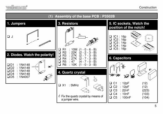
R1 : 10M (1 - 0 - 6 - B) R2 : 22K (2 - 2 - 3 - B) R3 : 27K (2 - 7 - 3 - B) R4 : 27K (2 - 7 - 3 - B) R5 : 47 (4 - 7 - 0 - B) R6 : 10K (1 - 0 - 3 - B)
3. Resistors
R...
Construction
(1) Assembly of the base PCB : P3502B
D1 : 1N4148 D2 : 1N4148 D3 : 1N4148 D4 : 1N4148 D5 : 1N4007
2. Diodes. Watch the polarity!
D...CATHODE
IC1 : 16p IC2 : 16p IC3 : 14p IC4 : 14p IC5 : 16p
5. IC sockets, Watch the position of the notch!
C1 : 12pF (12) C2 : 12pF (12) C3 : 22nF (223) C4 : 10nF (103) C5 : 100nF (104)
6. Capacitors
J
1. Jumpers
X1 : 5MHz
Fix the quartz crystal by means of
a jumper wire.
X...
4. Quartz crystal
6
Construction
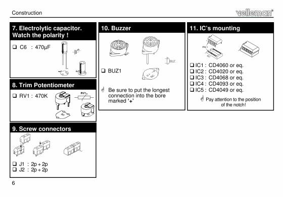
C6 : 470µF
7. Electrolytic capacitor. Watch the polarity !
C...
RV1 : 470K RV1
8. Trim Potentiometer
J1 : 2p + 2p J2 : 2p + 2p
9. Screw connectors
BUZ1 Be sure to put the longest
connection into the bore marked ‘+’
10. Buzzer
IC1 : CD4060 or eq. IC2 : CD4020 or eq. IC3 : CD4068 or eq. IC4 : CD4093 or eq. IC5 : CD4049 or eq. Pay attention to the position
of the notch!
11. IC’s mounting
PIN 1
1
7
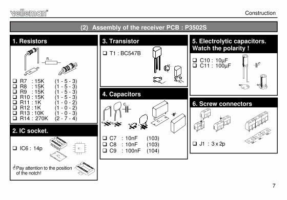
T1 : BC547B
3. Transistor
R7 : 15K (1 - 5 - 3) R8 : 15K (1 - 5 - 3) R9 : 15K (1 - 5 - 3) R10 : 15K (1 - 5 - 3) R11 : 1K (1 - 0 - 2) R12 : 1K (1 - 0 - 2) R13 : 10K (1 - 0 - 3) R14 : 270K (2 - 7 - 4)
1. Resistors
R...
Construction
(2) Assembly of the receiver PCB : P3502S
IC6 : 14p Pay attention to the position
of the notch!
2. IC socket.
C7 : 10nF (103) C8 : 10nF (103) C9 : 100nF (104)
4. Capacitors
C10 : 10µF C11 : 100µF
5. Electrolytic capacitors. Watch the polarity !
C...
J1 : 3 x 2p
6. Screw connectors

8
Construction
SENS 1 : MA40A5S or eq.(marked with T).
SENS 2 : MA40A5R or eq. (marked with CTD) Either on the print or connect them to the soldering terminals,
see chapter concerning the installation in the car.
7. Sensors
IC6 : TL074 Pay attention to the position
of the notch!
8. IC mounting
PIN 1
1

9
Connect the points GND, +V, RW, DIS, S1 and S2 of the main PCB to the corresponding points on the receiver PCB. Make sure that the distance between the receiver print and the base print is approx. 50cm.
Adjust the trimmer RV1 at the middle position RV1. Connect a 12VDC power supply (or a battery) between the points GND (-) and +. If you hold your hand or a sheet of paper in front of the sensors, you should hear the sound of the buzzer
when the distance from the object to the sensors decreases to about 70cm.
(3) TEST
Test
Mount the receiver print in a synthetic housing, which can be done in two different ways (depending on where it is built in on the car): A) With the sensors in upright position (fig. 1): Mount the four terminals for SENS1 and SENS2 Solder the sensors to the terminals so that they are in a traverse-position regarding the print. Realise the bores in the housing as shown on the drawing (fig. 4).
(4) INSTALLATION IN THE CAR

10
Install the print behind the bores using spacing sleeves,
so that the sensors are facing the bores properly without touching the housing.
B) With the sensors in horizontal position (fig. 2):
In this case the sensors are simply mounted on the print. Now realise the gaps in the housing as shown on the drawing 4.0 Install the print behind the bores using spacing sleeves, so that the sensors are
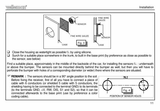
facing the bores properly without touching the housing. REMARK: Cover the bores at the inside of the housing with a piece of very fine wire gauze (see fig.3). (if
the meshes of the wire gauze are to wide to prevent penetration of splash-water, the gauze should be doubled up two or four times before fixing it to the bores). The sensors should be positioned properly AGAINST the wire gauze which has been placed behind the bores.
Make a small hole in the bottom of the housing in order to enable the evacuation of the water that eventually has infiltrated.
Installation
Fig. 1
Fig. 2
11
Installation
Close the housing as watertight as possible f.i. by using silicone. Surch for a suitable place somewhere in the trunk, to built in the base print (by preference as close as possible to
the sensor, see below)
Find a suitable place, approximately in the middle of the backside of the car, for installing the sensors f.i. : underneath or above the bumper. The sensors can be mounted directly behind the bumper as well, but then you will have to perforate the bumper with holes of a corresponding diameter (or wider) there where the sensors are situated. REMARK : The sensors should be in a 90° angle position to the soil.
Before fixing the receiver, first of all you have to connect a piece of cable with 6 conductors (or shielded 5 cable with 5 conductors, the shielding having to be connected to the terminal GND) to its terminals (to the terminals GND, +V, RW, DIS, S1 and S2), so that it can be connected afterwards to the base print (use by preference a color coding cable).
SENSOR
CASE
FINE WIRE GAUZE
FINE WIRE GAUZE
SENSOR
CASEFig. 3
POSITION OF SENSOR HOLES
Fig. 4

12
Connect the receiver to the base print. Connect the terminal GND of the base print to the - of the car (chassis) Connect the terminal ‘+’ of the base print to the ‘+’ of the reverse light.
(5) DEFINITIVE CONNECTION
Connection & use
The circuit is activated as soon as the gear is shifted in reverse (this is marked by a 'bip' tone) and will detect any obstacle within the range of the sensors, the detection distance (i.e. the sensitivity) being adjusted by means of the trimmer RV1. A distance of approx. 25 to 30cm from the backside of the car seems to be a value of practical use. First of all make some tests with the help of a second person who can survey the distance from the outside (in order to avoid damaging the coach-work). In case the buzzer cannot be heard clear enough, you can bring it closer to the driver by means of a 2 conductor extension cord. REMARK : Be carefully when washing the car that no water is getting into the receiver (eventually you
should cover the sensors by means of adhesive tape).
(6) USE

13 P
35
02
B
GND
+V
RW
S1 S2
P3502B
P3502S
GND +V RW D
IS
+ GND
GND+V
RW DIS
S1 S
2
S1 S2
+
-
Connection

14
(7) Schematic diagram (Control section)
Schematic diagram

15
PCB
PCB layout P3502S
PCB layout P3502B
(8) PCB’s

Modifications and typographical errors reserved ,© Velleman nv. H3502IP’2 - 2014 (rev3)
5 4 1 0 3 2 9 2 9 1 5 9 4
VELLEMAN NV Legen Heirweg 33, B-9890 GAVERE
Belgium (Europe)