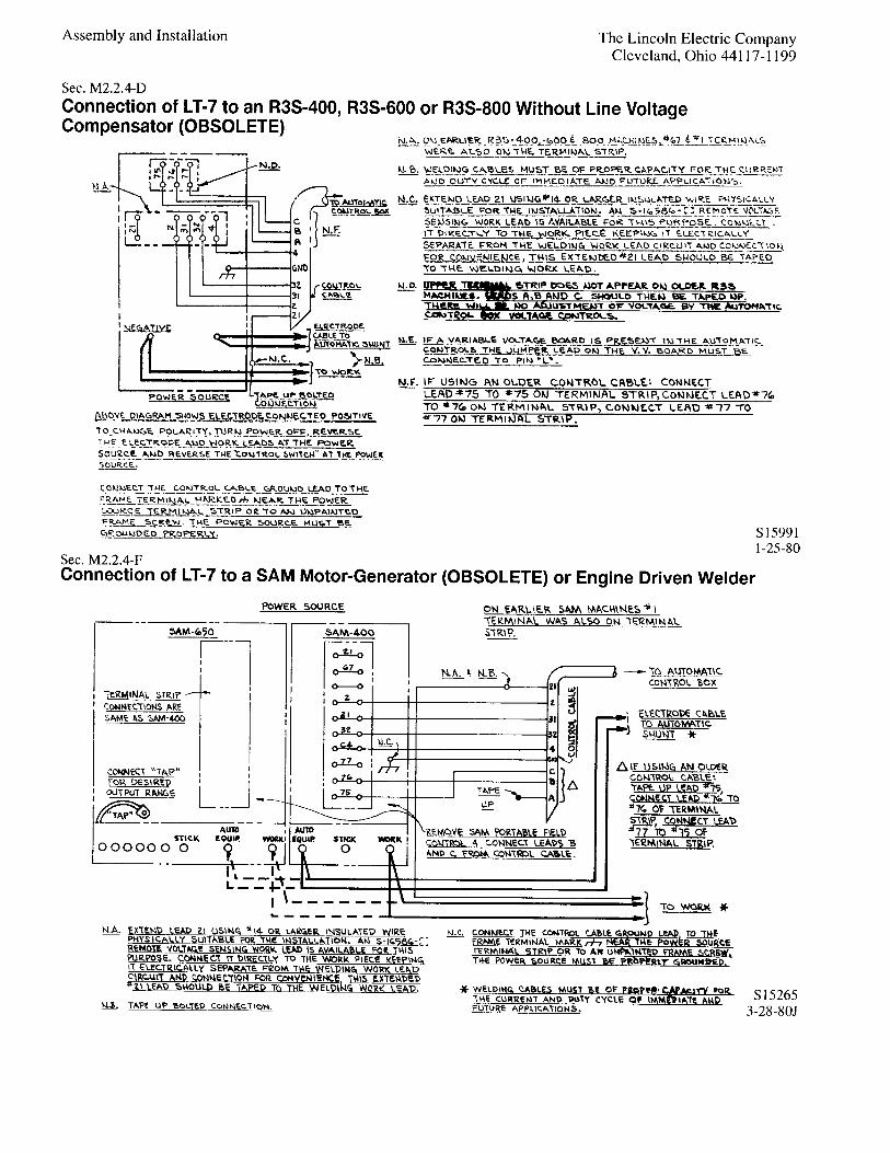
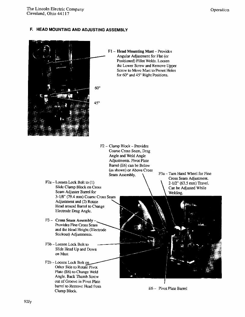
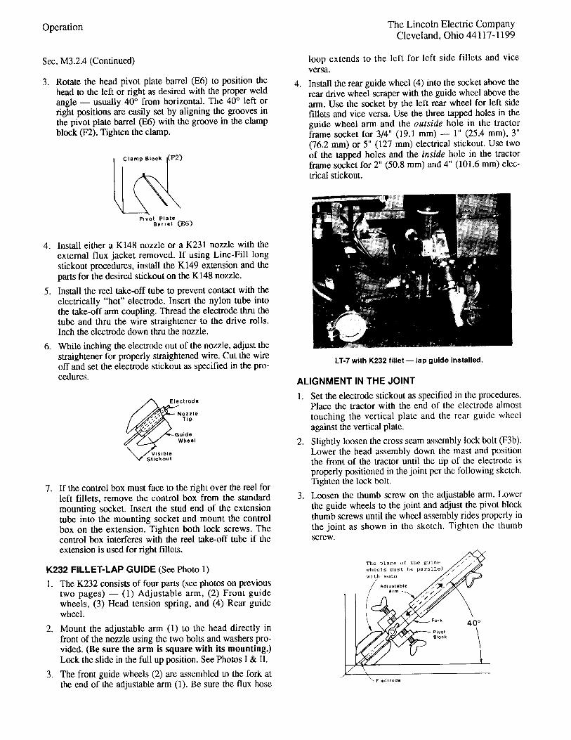
K227, K395 and K395-1 - Red-D-Arc Tractor Operator manual IM279.pdf · LT-7 Lightweight Tractor...
88
LT-7 Lightweight Tractor OPERATOR’S MANUAL IM-279-C November, 2006 K227, K395 and K395-1 A Complete Automatic DC Submerged Arc Wire Feeder on a Self-Propelled Trackless Carriage Safety Depends on You Lincoln arc welding and cutting equipment is designed and built with safety in mind. However, your overall safety can be increased by proper installation ... and thought- ful operation on your part. DO NOT INSTALL OPERATE OR REPAIR THIS EQUIPMENT WITHOUT READING THIS MANUAL AND THE SAFETY PRECAUTIONS CONTAINED THROUGHOUT. And, most importantly, think before you act and be careful. Damage Claims When this equipment is shipped, title passes to the purchaser upon receipt by the carrier. Consequently, claims for material damaged in shipment must be made by the purchaser against the transportation company at the time the shipment is received. • Sales and Service through Subsidiaries and Distributors Worldwide • Cleveland, Ohio 44117-1199 U.S.A. TEL: 216.481.8100 FAX: 216.486.1751 WEB SITE: www.lincolnelectric.com • World's Leader in Welding and Cutting Products • Copyright © 2006 Lincoln Global Inc.
Transcript of K227, K395 and K395-1 - Red-D-Arc Tractor Operator manual IM279.pdf · LT-7 Lightweight Tractor...

LT-7 Lightweight Tractor
OPERATOR’S MANUAL
IM-279-CNovember, 2006
K227, K395 and K395-1A Complete Automatic DC Submerged Arc
Wire Feeder on a Self-Propelled Trackless Carriage
Safety Depends on YouLincoln arc welding and cuttingequipment is designed and builtwith safety in mind. However, youroverall safety can be increased byproper installation ... and thought-ful operation on your part. DONOT INSTALL OPERATE ORREPAIR THIS EQUIPMENTWITHOUT READING THISMANUAL AND THE SAFETYPRECAUTIONS CONTAINEDTHROUGHOUT. And, mostimportantly, think before you actand be careful.
Damage ClaimsWhen this equipment is shipped,title passes to the purchaser uponreceipt by the carr ier.Consequently, claims for materialdamaged in shipment must bemade by the purchaser againstthe transportation company at thetime the shipment is received.
• Sales and Service through Subsidiaries and Distributors Worldwide •
Cleveland, Ohio 44117-1199 U.S.A. TEL: 216.481.8100 FAX: 216.486.1751 WEB SITE: www.lincolnelectric.com
• World's Leader in Welding and Cutting Products •
Copyright © 2006 Lincoln Global Inc.

FOR ENGINEpowered equipment.
1.a. Turn the engine off before troubleshooting and maintenancework unless the maintenance work requires it to be running.
____________________________________________________1.b. Operate engines in open, well-ventilated
areas or vent the engine exhaust fumes outdoors.
____________________________________________________1.c. Do not add the fuel near an open flame
welding arc or when the engine is running.Stop the engine and allow it to cool beforerefueling to prevent spilled fuel from vaporiz-ing on contact with hot engine parts andigniting. Do not spill fuel when filling tank. Iffuel is spilled, wipe it up and do not startengine until fumes have been eliminated.
____________________________________________________1.d. Keep all equipment safety guards, covers and devices in
position and in good repair.Keep hands, hair, clothing andtools away from V-belts, gears, fans and all other movingparts when starting, operating or repairing equipment.
____________________________________________________
1.e. In some cases it may be necessary to remove safetyguards to perform required maintenance. Removeguards only when necessary and replace them when themaintenance requiring their removal is complete.Always use the greatest care when working near movingparts.
___________________________________________________1.f. Do not put your hands near the engine fan.
Do not attempt to override the governor oridler by pushing on the throttle control rodswhile the engine is running.
___________________________________________________1.g. To prevent accidentally starting gasoline engines while
turning the engine or welding generator during maintenancework, disconnect the spark plug wires, distributor cap ormagneto wire as appropriate.
iSAFETYi
ARC WELDING CAN BE HAZARDOUS. PROTECT YOURSELF AND OTHERS FROM POSSIBLE SERIOUS INJURY OR DEATH.KEEP CHILDREN AWAY. PACEMAKER WEARERS SHOULD CONSULT WITH THEIR DOCTOR BEFORE OPERATING.
Read and understand the following safety highlights. For additional safety information, it is strongly recommended that youpurchase a copy of “Safety in Welding & Cutting - ANSI Standard Z49.1” from the American Welding Society, P.O. Box351040, Miami, Florida 33135 or CSA Standard W117.2-1974. A Free copy of “Arc Welding Safety” booklet E205 is availablefrom the Lincoln Electric Company, 22801 St. Clair Avenue, Cleveland, Ohio 44117-1199.
BE SURE THAT ALL INSTALLATION, OPERATION, MAINTENANCE AND REPAIR PROCEDURES AREPERFORMED ONLY BY QUALIFIED INDIVIDUALS.
WARNING
Mar ‘95
ELECTRIC ANDMAGNETIC FIELDSmay be dangerous
2.a. Electric current flowing through any conductor causeslocalized Electric and Magnetic Fields (EMF). Weldingcurrent creates EMF fields around welding cables andwelding machines
2.b. EMF fields may interfere with some pacemakers, andwelders having a pacemaker should consult their physicianbefore welding.
2.c. Exposure to EMF fields in welding may have other healtheffects which are now not known.
2.d. All welders should use the following procedures in order tominimize exposure to EMF fields from the welding circuit:
2.d.1. Route the electrode and work cables together - Securethem with tape when possible.
2.d.2. Never coil the electrode lead around your body.
2.d.3. Do not place your body between the electrode andwork cables. If the electrode cable is on your right side, the work cable should also be on your right side.
2.d.4. Connect the work cable to the workpiece as close aspossible to the area being welded.
2.d.5. Do not work next to welding power source.
1.h. To avoid scalding, do not remove theradiator pressure cap when the engine ishot.
CALIFORNIA PROPOSITION 65 WARNINGS
Diesel engine exhaust and some of its constituentsare known to the State of California to cause can-cer, birth defects, and other reproductive harm.
The engine exhaust from this product containschemicals known to the State of California to causecancer, birth defects, or other reproductive harm.
The Above For Diesel Engines The Above For Gasoline Engines

iiSAFETYii
ARC RAYS can burn.4.a. Use a shield with the proper filter and cover
plates to protect your eyes from sparks andthe rays of the arc when welding or observingopen arc welding. Headshield and filter lensshould conform to ANSI Z87. I standards.
4.b. Use suitable clothing made from durable flame-resistantmaterial to protect your skin and that of your helpers fromthe arc rays.
4.c. Protect other nearby personnel with suitable, non-flammablescreening and/or warn them not to watch the arc nor exposethemselves to the arc rays or to hot spatter or metal.
ELECTRIC SHOCK cankill.3.a. The electrode and work (or ground) circuits
are electrically “hot” when the welder is on.Do not touch these “hot” parts with your bareskin or wet clothing. Wear dry, hole-free
gloves to insulate hands.
3.b. Insulate yourself from work and ground using dry insulation.Make certain the insulation is large enough to cover your fullarea of physical contact with work and ground.
In addition to the normal safety precautions, if weldingmust be performed under electrically hazardousconditions (in damp locations or while wearing wetclothing; on metal structures such as floors, gratings orscaffolds; when in cramped positions such as sitting,kneeling or lying, if there is a high risk of unavoidable oraccidental contact with the workpiece or ground) usethe following equipment:
• Semiautomatic DC Constant Voltage (Wire) Welder.• DC Manual (Stick) Welder.• AC Welder with Reduced Voltage Control.
3.c. In semiautomatic or automatic wire welding, the electrode,electrode reel, welding head, nozzle or semiautomaticwelding gun are also electrically “hot”.
3.d. Always be sure the work cable makes a good electricalconnection with the metal being welded. The connectionshould be as close as possible to the area being welded.
3.e. Ground the work or metal to be welded to a good electrical(earth) ground.
3.f. Maintain the electrode holder, work clamp, welding cable andwelding machine in good, safe operating condition. Replacedamaged insulation.
3.g. Never dip the electrode in water for cooling.
3.h. Never simultaneously touch electrically “hot” parts ofelectrode holders connected to two welders because voltagebetween the two can be the total of the open circuit voltageof both welders.
3.i. When working above floor level, use a safety belt to protectyourself from a fall should you get a shock.
3.j. Also see Items 6.c. and 8.
FUMES AND GASEScan be dangerous.5.a. Welding may produce fumes and gases
hazardous to health. Avoid breathing thesefumes and gases. When welding, keepyour head out of the fume. Use enoughventilation and/or exhaust at the arc to keep
fumes and gases away from the breathing zone. Whenwelding with electrodes which require specialventilation such as stainless or hard facing (seeinstructions on container or MSDS) or on lead orcadmium plated steel and other metals or coatingswhich produce highly toxic fumes, keep exposure aslow as possible and below Threshold Limit Values (TLV)using local exhaust or mechanical ventilation. Inconfined spaces or in some circumstances, outdoors, arespirator may be required. Additional precautions arealso required when welding on galvanized steel.
5. b. The operation of welding fume control equipment is affectedby various factors including proper use and positioning ofthe equipment, maintenance of the equipment and the spe-cific welding procedure and application involved. Workerexposure level should be checked upon installation andperiodically thereafter to be certain it is within applicableOSHA PEL and ACGIH TLV limits.
5.c. Do not weld in locations near chlorinated hydrocarbon vaporscoming from degreasing, cleaning or spraying operations.The heat and rays of the arc can react with solvent vapors toform phosgene, a highly toxic gas, and other irritating prod-ucts.
5.d. Shielding gases used for arc welding can displace air andcause injury or death. Always use enough ventilation,especially in confined areas, to insure breathing air is safe.
5.e. Read and understand the manufacturer’s instructions for thisequipment and the consumables to be used, including thematerial safety data sheet (MSDS) and follow youremployer’s safety practices. MSDS forms are available fromyour welding distributor or from the manufacturer.
5.f. Also see item 1.b.
AUG 06

FOR ELECTRICALLYpowered equipment.
8.a. Turn off input power using the disconnectswitch at the fuse box before working onthe equipment.
8.b. Install equipment in accordance with the U.S. NationalElectrical Code, all local codes and the manufacturer’srecommendations.
8.c. Ground the equipment in accordance with the U.S. NationalElectrical Code and the manufacturer’s recommendations.
CYLINDER may explodeif damaged.7.a. Use only compressed gas cylinders
containing the correct shielding gas for theprocess used and properly operatingregulators designed for the gas and
pressure used. All hoses, fittings, etc. should be suitable forthe application and maintained in good condition.
7.b. Always keep cylinders in an upright position securelychained to an undercarriage or fixed support.
7.c. Cylinders should be located:• Away from areas where they may be struck or subjected tophysical damage.
• A safe distance from arc welding or cutting operations andany other source of heat, sparks, or flame.
7.d. Never allow the electrode, electrode holder or any otherelectrically “hot” parts to touch a cylinder.
7.e. Keep your head and face away from the cylinder valve outletwhen opening the cylinder valve.
7.f. Valve protection caps should always be in place and handtight except when the cylinder is in use or connected foruse.
7.g. Read and follow the instructions on compressed gascylinders, associated equipment, and CGA publication P-l,“Precautions for Safe Handling of Compressed Gases inCylinders,” available from the Compressed Gas Association1235 Jefferson Davis Highway, Arlington, VA 22202.
iiiSAFETYiii
Mar ‘95
WELDING SPARKS cancause fire or explosion.6.a. Remove fire hazards from the welding area.
If this is not possible, cover them to preventthe welding sparks from starting a fire.Remember that welding sparks and hot
materials from welding can easily go through small cracksand openings to adjacent areas. Avoid welding nearhydraulic lines. Have a fire extinguisher readily available.
6.b. Where compressed gases are to be used at the job site,special precautions should be used to prevent hazardoussituations. Refer to “Safety in Welding and Cutting” (ANSIStandard Z49.1) and the operating information for theequipment being used.
6.c. When not welding, make certain no part of the electrodecircuit is touching the work or ground. Accidental contactcan cause overheating and create a fire hazard.
6.d. Do not heat, cut or weld tanks, drums or containers until theproper steps have been taken to insure that such procedureswill not cause flammable or toxic vapors from substancesinside. They can cause an explosion even though they havebeen “cleaned”. For information, purchase “RecommendedSafe Practices for the Preparation for Welding and Cutting ofContainers and Piping That Have Held HazardousSubstances”, AWS F4.1 from the American Welding Society(see address above).
6.e. Vent hollow castings or containers before heating, cutting orwelding. They may explode.
6.f. Sparks and spatter are thrown from the welding arc. Wear oilfree protective garments such as leather gloves, heavy shirt,cuffless trousers, high shoes and a cap over your hair. Wearear plugs when welding out of position or in confined places.Always wear safety glasses with side shields when in awelding area.
6.g. Connect the work cable to the work as close to the weldingarea as practical. Work cables connected to the buildingframework or other locations away from the welding areaincrease the possibility of the welding current passingthrough lifting chains, crane cables or other alternate cir-cuits. This can create fire hazards or overheat lifting chainsor cables until they fail.
6.h. Also see item 1.c.

ivSAFETYiv
PRÉCAUTIONS DE SÛRETÉPour votre propre protection lire et observer toutes les instructionset les précautions de sûreté specifiques qui parraissent dans cemanuel aussi bien que les précautions de sûreté générales suiv-antes:
Sûreté Pour Soudage A L’Arc1. Protegez-vous contre la secousse électrique:
a. Les circuits à l’électrode et à la piéce sont sous tensionquand la machine à souder est en marche. Eviter toujourstout contact entre les parties sous tension et la peau nueou les vétements mouillés. Porter des gants secs et sanstrous pour isoler les mains.
b. Faire trés attention de bien s’isoler de la masse quand onsoude dans des endroits humides, ou sur un planchermetallique ou des grilles metalliques, principalement dans les positions assis ou couché pour lesquelles une grandepartie du corps peut être en contact avec la masse.
c. Maintenir le porte-électrode, la pince de masse, le câblede soudage et la machine à souder en bon et sûr étatdefonctionnement.
d.Ne jamais plonger le porte-électrode dans l’eau pour lerefroidir.
e. Ne jamais toucher simultanément les parties sous tensiondes porte-électrodes connectés à deux machines à souderparce que la tension entre les deux pinces peut être letotal de la tension à vide des deux machines.
f. Si on utilise la machine à souder comme une source decourant pour soudage semi-automatique, ces precautionspour le porte-électrode s’applicuent aussi au pistolet desoudage.
2. Dans le cas de travail au dessus du niveau du sol, se protégercontre les chutes dans le cas ou on recoit un choc. Ne jamaisenrouler le câble-électrode autour de n’importe quelle partiedu corps.
3. Un coup d’arc peut être plus sévère qu’un coup de soliel,donc:
a. Utiliser un bon masque avec un verre filtrant appropriéainsi qu’un verre blanc afin de se protéger les yeux du ray-onnement de l’arc et des projections quand on soude ouquand on regarde l’arc.
b. Porter des vêtements convenables afin de protéger lapeau de soudeur et des aides contre le rayonnement del‘arc.
c. Protéger l’autre personnel travaillant à proximité ausoudage à l’aide d’écrans appropriés et non-inflammables.
4. Des gouttes de laitier en fusion sont émises de l’arc desoudage. Se protéger avec des vêtements de protection libresde l’huile, tels que les gants en cuir, chemise épaisse, pan-talons sans revers, et chaussures montantes.
5. Toujours porter des lunettes de sécurité dans la zone desoudage. Utiliser des lunettes avec écrans lateraux dans leszones où l’on pique le laitier.
6. Eloigner les matériaux inflammables ou les recouvrir afin deprévenir tout risque d’incendie dû aux étincelles.
7. Quand on ne soude pas, poser la pince à une endroit isolé dela masse. Un court-circuit accidental peut provoquer unéchauffement et un risque d’incendie.
8. S’assurer que la masse est connectée le plus prés possiblede la zone de travail qu’il est pratique de le faire. Si on placela masse sur la charpente de la construction ou d’autresendroits éloignés de la zone de travail, on augmente le risquede voir passer le courant de soudage par les chaines de lev-age, câbles de grue, ou autres circuits. Cela peut provoquerdes risques d’incendie ou d’echauffement des chaines et descâbles jusqu’à ce qu’ils se rompent.
9. Assurer une ventilation suffisante dans la zone de soudage.Ceci est particuliérement important pour le soudage de tôlesgalvanisées plombées, ou cadmiées ou tout autre métal quiproduit des fumeés toxiques.
10. Ne pas souder en présence de vapeurs de chlore provenantd’opérations de dégraissage, nettoyage ou pistolage. Lachaleur ou les rayons de l’arc peuvent réagir avec les vapeursdu solvant pour produire du phosgéne (gas fortement toxique)ou autres produits irritants.
11. Pour obtenir de plus amples renseignements sur la sûreté,voir le code “Code for safety in welding and cutting” CSAStandard W 117.2-1974.
PRÉCAUTIONS DE SÛRETÉ POURLES MACHINES À SOUDER ÀTRANSFORMATEUR ET ÀREDRESSEUR
1. Relier à la terre le chassis du poste conformement au code del’électricité et aux recommendations du fabricant. Le dispositifde montage ou la piece à souder doit être branché à unebonne mise à la terre.
2. Autant que possible, I’installation et l’entretien du poste seronteffectués par un électricien qualifié.
3. Avant de faires des travaux à l’interieur de poste, la debranch-er à l’interrupteur à la boite de fusibles.
4. Garder tous les couvercles et dispositifs de sûreté à leurplace.
Mar. ‘93

Thank You for selecting a QUALITY product by Lincoln Electric. We want youto take pride in operating this Lincoln Electric Company product••• as much pride as we have in bringing this product to you!
Read this Operators Manual completely before attempting to use this equipment. Save this manual and keep ithandy for quick reference. Pay particular attention to the safety instructions we have provided for your protection.The level of seriousness to be applied to each is explained below:
WARNINGThis statement appears where the information must be followed exactly to avoid serious personal injury orloss of life.
This statement appears where the information must be followed to avoid minor personal injury or damage tothis equipment.
CAUTION
Please Examine Carton and Equipment For Damage ImmediatelyWhen this equipment is shipped, title passes to the purchaser upon receipt by the carrier. Consequently, Claimsfor material damaged in shipment must be made by the purchaser against the transportation company at thetime the shipment is received.
Please record your equipment identification information below for future reference. This information can befound on your machine nameplate.
Product _________________________________________________________________________________
Model Number ___________________________________________________________________________
Code Number or Date Code_________________________________________________________________
Serial Number____________________________________________________________________________
Date Purchased___________________________________________________________________________
Where Purchased_________________________________________________________________________
Whenever you request replacement parts or information on this equipment, always supply the information youhave recorded above. The code number is especially important when identifying the correct replacement parts.
vv
On-Line Product Registration
- Register your machine with Lincoln Electric either via fax or over the Internet.
• For faxing: Complete the form on the back of the warranty statement included in the literature packetaccompanying this machine and fax the form per the instructions printed on it.
• For On-Line Registration: Go to our WEB SITE at www.lincolnelectric.com. Choose “Quick Links” and then“Product Registration”. Please complete the form and submit your registration.


06-02-2006
P-117-AP-117-A
SEC. M7LT-7
K227 OR K395LIGHTWEIGHT TRACTOR
PARTS LISTModel Index
RETURN TO MAIN INDEX
General Assembly . . . . . . . . . . . . . . . . . . . . . . . . . . . . . . . . . . . . . . . . . . . . . . . . . . . . . . . . . . . . . . . P-117-CHead Assembly . . . . . . . . . . . . . . . . . . . . . . . . . . . . . . . . . . . . . . . . . . . . . . . . . . . . . . . . . . . . . . . . . P-117-DWire Straightener . . . . . . . . . . . . . . . . . . . . . . . . . . . . . . . . . . . . . . . . . . . . . . . . . . . . . . . . . . . . . . . . P-117-FFront Wheel Assembly . . . . . . . . . . . . . . . . . . . . . . . . . . . . . . . . . . . . . . . . . . . . . . . . . . . . . . . . . . . . P-117-GK229, K230 & K232 Optional Guide Kits . . . . . . . . . . . . . . . . . . . . . . . . . . . . . . . . . . . . . . . . . . . . . . P-117-JControl Box . . . . . . . . . . . . . . . . . . . . . . . . . . . . . . . . . . . . . . . . . . . . . . . . . . . . . . . . . . . . . . . . . . . . . P-117-LInternal Controls Assembly . . . . . . . . . . . . . . . . . . . . . . . . . . . . . . . . . . . . . . . . . . . . . . . . . . . . . . . . . P-117-MVertical Head Lift Adjuster . . . . . . . . . . . . . . . . . . . . . . . . . . . . . . . . . . . . . . . . . . . . . . . . . . . . . . . . . P-117-OK277-1 and -2 Tiny Twinarc Adapter Kits . . . . . . . . . . . . . . . . . . . . . . . . . . . . . . . . . . . . . . . . . . . . . . P-117-PK285 Concentric Flux Cone . . . . . . . . . . . . . . . . . . . . . . . . . . . . . . . . . . . . . . . . . . . . . . . . . . . . . . . . P-114-JK231 Nozzle Assembly . . . . . . . . . . . . . . . . . . . . . . . . . . . . . . . . . . . . . . . . . . . . . . . . . . . . . . . . . . . . P-101-MK148 Fully Automatic Nozzles and Extensions . . . . . . . . . . . . . . . . . . . . . . . . . . . . . . . . . . . . . . . . . P-101-KK224 Solid-State Remote Field Control . . . . . . . . . . . . . . . . . . . . . . . . . . . . . . . . . . . . . . . . . . . . . . . P-114-HK129 Sub-Arc Twinarc . . . . . . . . . . . . . . . . . . . . . . . . . . . . . . . . . . . . . . . . . . . . . . . . . . . . . . . . . . . . P-101-GK281 Wire Straightener . . . . . . . . . . . . . . . . . . . . . . . . . . . . . . . . . . . . . . . . . . . . . . . . . . . . . . . . . . . P-101-G.2K396 Track Sections . . . . . . . . . . . . . . . . . . . . . . . . . . . . . . . . . . . . . . . . . . . . . . . . . . . . . . . . . . . . . P-117-RConversion Kit (To convert K227 Tractor to Track Model) . . . . . . . . . . . . . . . . . . . . . . . . . . . . . . . . . Order K400

GENERAL ASSEMBLY
P-117-CP-117-C
06-06-2001
(ONE OF THREE)
1914
7
20
18
4
15
21
5
16A
3
16B
17
6
1
11
2
10
12
13
9C
9B9E
9D 9A
9
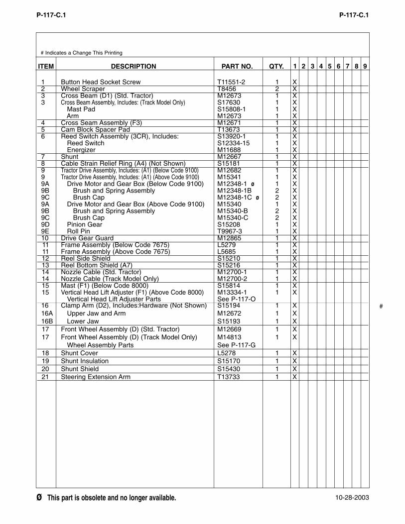
1 Button Head Socket Screw T11551-2 1 X2 Wheel Scraper T8456 2 X3 Cross Beam (D1) (Std. Tractor) M12673 1 X3 Cross Beam Assembly, Includes: (Track Model Only) S17630 1 X
Mast Pad S15808-1 1 XArm M12673 1 X
4 Cross Seam Assembly (F3) M12671 1 X5 Cam Block Spacer Pad T13673 1 X6 Reed Switch Assembly (3CR), Includes: S13920-1 1 X
Reed Switch S12334-15 1 XEnergizer M11688 1 X
7 Shunt M12667 1 X8 Cable Strain Relief Ring (A4) (Not Shown) S15181 1 X9 Tractor Drive Assembly, Includes: (A1) (Below Code 9100) M12682 1 X9 Tractor Drive Assembly, Includes: (A1) (Above Code 9100) M15341 1 X9A Drive Motor and Gear Box (Below Code 9100) M12348-1 ø 1 X9B Brush and Spring Assembly M12348-1B 2 X9C Brush Cap M12348-1C ø 2 X9A Drive Motor and Gear Box (Above Code 9100) M15340 1 X9B Brush and Spring Assembly M15340-B 2 X9C Brush Cap M15340-C 2 X9D Pinion Gear S15208 1 X9E Roll Pin T9967-3 1 X10 Drive Gear Guard M12865 1 X11 Frame Assembly (Below Code 7675) L5279 1 X11 Frame Assembly (Above Code 7675) L5685 1 X12 Reel Side Shield S15210 1 X13 Reel Bottom Shield (A7) S15216 1 X14 Nozzle Cable (Std. Tractor) M12700-1 1 X14 Nozzle Cable (Track Model Only) M12700-2 1 X15 Mast (F1) (Below Code 8000) S15814 1 X15 Vertical Head Lift Adjuster (F1) (Above Code 8000) M13334-1 1 X
Vertical Head Lift Adjuster Parts See P-117-O16 Clamp Arm (D2), Includes:Hardware (Not Shown) S15194 1 X16A Upper Jaw and Arm M12672 1 X16B Lower Jaw S15193 1 X17 Front Wheel Assembly (D) (Std. Tractor) M12669 1 X17 Front Wheel Assembly (D) (Track Model Only) M14813 1 X
Wheel Assembly Parts See P-117-G18 Shunt Cover L5278 1 X19 Shunt Insulation S15170 1 X20 Shunt Shield S15430 1 X21 Steering Extension Arm T13733 1 X
10-28-2003
ITEM DESCRIPTION PART NO. QTY. 1 2 3 4 5 6 7 8 9
P-117-C.1P-117-C.1
# Indicates a Change This Printing
ø This part is obsolete and no longer available.
#

General Assembly
P-117-C.2P-117-C.2
11-18-2005
(TWO OF THREE)
13
16
15
14
12A
12B
3
21B
10
17A17B 7
8
9
64
54
9 8
7
11A11B
10
1A
11
11
18
19

1A Clutch Handle (A2) T9781-43 1 X1B Knob T10889 1 X2 Clutch Spring Cam T13728 1 X3 Clutch Fork Assembly S15164 1 X4 Roll Pin T9967-6 2 X5 Drive Gear Key M8776-83 1 X6 Drive Gear S15172 1 X7 Bearing S16645-2 2 X8 Wheel Key M8776-84 1 X9 Axle S15171 1 X10 Retaining Ring S9776-16 2 X11 Rear Wheel (A3) (Std. Tractor) S15191 2 X11 Gear Wheel Assembly, Includes: (Track Model Only) S17632 1 X11A Gear Wheel S17631 1 X11B Wheel S17635 1 X12A Clutch Handle (A2) T9781-44 1 X12B Knob T10889 1 X13 Flux Hopper Assembly, Includes: (E7) M12691 1 X
Flux Flow Valve S15223 1 X14 Wire Straightener (E3) & Wire Straightener Parts See P-117-F 1 X15 Flux Tube and Tip T13835 1 X16 Pointer Assembly S15287 1 X
Pointer Clamp for K148 Nozzle (Not Shown) S15286-2 1 X17 Rail Wheel Assembly, Includes: (Track Model Only) S17634-1 1 X17A Rail Wheel S17633 1 X17B Wheel S17635 1 X18 Bumper Handle Assembly, Includes: M13051 1 X19 Handle S15659 1 X
11-18-2005
ITEM DESCRIPTION PART NO. QTY. 1 2 3 4 5 6 7 8 9
P-117-C.3P-117-C.3
# Indicates a Change This Printing
##

General Assembly
P-117-C.4P-117-C.4
51
8
11
10
12
13
2
9
6
714
4
3
12-28-98
Three of Three

1 Electrode Feed Tube S14004-2 1 X2 Electrode Take-Off Arm S15195 1 X3 Control Box (C) See P-117-L 1 X4 Control Box Support (C4) (Below Code 7675) S15242 1 X4 Control Box Support (C4) (Above Code 7675) S15820 1 X5 Wire Reel (B3) L4604 1 X6 Reel Mount Assembly (B1) (Below Code 7675) M12787 ø 1 X6 Reel Mount Assembly (B1) (Above Code 7675) M13255 1 X7 Reel Top Shield Support S15446 1 X8 Reel Top Shield (Below Code 7675) T13811 1 X8 Reel Top Shield (Above Code 7675) T14021 1 X9 Insulating Washer S10773-47 1 X10 Wire Reel Shaft S15199 1 X11 Roll Pin T9967-9 1 X12 Plain Washer S9262-26 1 X13 Insulating Tube T12478-5 1 X14 Control Box Mount Extension S15184-1 1 X
07-19-2001
Use only the parts marked “X” in the column under theheading number called for in the model index page.
ITEM DESCRIPTION PART NO. QTY. 1 2 3 4 5 6 7 8 9
P-117-C.5P-117-C.5
# Indicates a Change This Printing
#
ø This part is obsolete and no longer available.

HEAD ASSEMBLY
P-117-DP-117-D
12-28-98
20
18
1A
30
11B
2611A
11C
11D
11E
15
21
14
13
16
}
19
1722
12
5
342
1B
278
6
10
7 1069
23A
23D
23B
23E
24
29
2823C

1A Gear Box Assembly, Includes: L5504-1 1 XAssembly without Motor L5504-1A 1 X
1B Drive Motor Assembly, Includes: M12711 1 XDrive Motor NSS 1 XBrush 8 Spring Assembly M13274-6 2 XBrush Cap M13274-7 2 X
Pinion Gear T13183 1 XRoll Pin T9967-33 1 X
Groove Pin, Motor to Gear Box T10580-6 1 XSocket Head Screw, Motor to Gear Box T9447-7 2 X
2 Drive Roll S14541-3/16 2 X3 Sems Screw T10082-26 1 X4 Collar Assembly T12341 1 X5 Key M8776-82 1 X6 Nozzle Clip T13715 2 X7 Outgoing Guide Tube S15230-3/16 1 X8 Nozzle Mount Pad S15209 1 X9 Socket Head Cap Screw T9447-9 2 X
10 5/16-18 x 1.00 Hex Head Screw CF000062 2 X11A Hex Head Screw 5/16-18 x 1.25 2 X11B Insulating Tube, Pivot Arm Mounting (Code 7429 Only) T7305-41 ø 2 X11B Insulating Tube, Pivot Arm Mounting T7305-43 2 X11C Insulating Washers, Pivot Arm Mounting (Code 7429 Only) S10773-41 2 X11C Insulating Washers, Pivot Arm Mounting S10773-58 2 X11D Flat Washer S9262-121 2 X11E Lock Washer E106A-14 2 X12 Socket Set Screw S11604-8 4 X13 Pivot Pin T13271-1 1 X14 Idle Roll Assembly S16666-1 1 X15 Thread Forming Screw S9225-21 1 X16 Spring T10247-11 1 X17 Hex Nut 5/16-18 1 X18 Incoming Guide Tube S15229-3/16 1 X19 Idle Roll Pull Arm S14533 1 X20 Straightener Mounting Block T13672 1 X21 Idle Roll Arm Bracket T14443 1 X22 Flat Washer S9262-121 1 X23A Hex Head Screw 5/16-18 x 1.25 2 X23B Insulating Washer S10773-58 2 X23C Insulating Tube T7028-134 2 X23D Lock Washer E106A-14 2 X23E Flat Washer S9262-121 2 X24 Fillet-Lap Attachment, Mounting Plate S15398 1 X26 Pivot Plate and Arm Assembly (Code 7429 Only) S15220 ø 1 X26 Pivot Plate and Arm Assembly S15220-1 1 X27 Spacer S10153-37 1 X28 Socket Head Cap Screw T9447-10 1 X29 Insulation T13695 1 X30 Insulation, Pivot Arm Mounting (Code 7429 Only) S15217 ø 1 X30 Insulation, Pivot Arm Mounting S15217-1 1 X
11-18-2005
ITEM DESCRIPTION PART NO. QTY. 1 2 3 4 5 6 7 8 9
P-117-D.1P-117-D.1
# Indicates a Change This Printing
ø This part is obsolete and no longer available.NSS - Not sold separately
#

Wire Straightener, Includes All Below: M12680 11 Roll Pin T9967-5 12 Screw Bushing T10585 13 Slide Screw Assembly S10159 14 Body Assembly M12679 15 Wire Guide Wheel M9300-55 26 Hex Head Bolt 5/16-18 x 1.25 17 Slide Bushing T10584 18 Flat Washer S9262-140 29 Lock Washer E106A-14 1
10 Hex Nut 5/16-18 1
12-28-98
ITEM DESCRIPTION PART NO. QTY. 1 2 3 4 5 6 7 8 9
P-117-FP-117-F
# Indicates a Change This Printing
WIRE STRAIGHTENER
#
#
M126803-28-75P
6
5
4
3
2
1
7
8
9
10
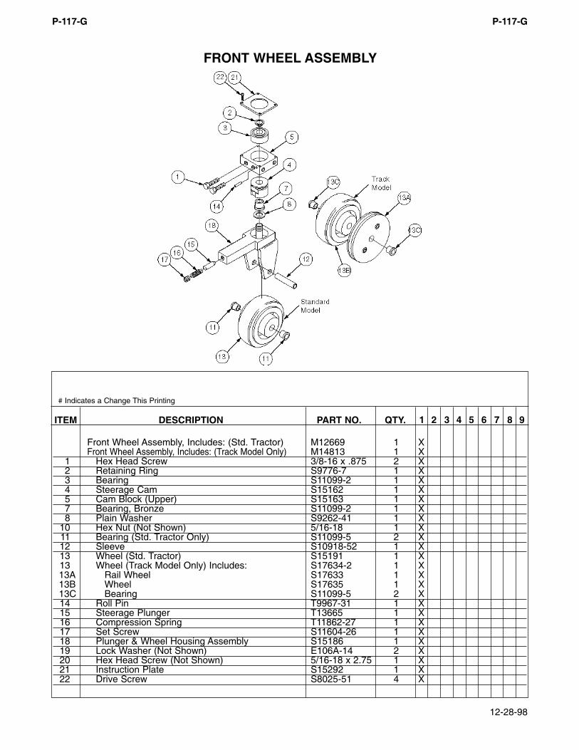
Front Wheel Assembly, Includes: (Std. Tractor) M12669 1 XFront Wheel Assembly, Includes: (Track Model Only) M14813 1 X
1 Hex Head Screw 3/8-16 x .875 2 X2 Retaining Ring S9776-7 1 X3 Bearing S11099-2 1 X4 Steerage Cam S15162 1 X5 Cam Block (Upper) S15163 1 X7 Bearing, Bronze S11099-2 1 X8 Plain Washer S9262-41 1 X
10 Hex Nut (Not Shown) 5/16-18 1 X11 Bearing (Std. Tractor Only) S11099-5 2 X12 Sleeve S10918-52 1 X13 Wheel (Std. Tractor) S15191 1 X13 Wheel (Track Model Only) Includes: S17634-2 1 X13A Rail Wheel S17633 1 X13B Wheel S17635 1 X13C Bearing S11099-5 2 X14 Roll Pin T9967-31 1 X15 Steerage Plunger T13665 1 X16 Compression Spring T11862-27 1 X17 Set Screw S11604-26 1 X18 Plunger & Wheel Housing Assembly S15186 1 X19 Lock Washer (Not Shown) E106A-14 2 X20 Hex Head Screw (Not Shown) 5/16-18 x 2.75 1 X21 Instruction Plate S15292 1 X22 Drive Screw S8025-51 4 X
12-28-98
ITEM DESCRIPTION PART NO. QTY. 1 2 3 4 5 6 7 8 9
P-117-GP-117-G
# Indicates a Change This Printing
FRONT WHEEL ASSEMBLY

NOTES

Butt Guide Kit, Includes: K230 1Guide Wheel Bracket S15259 1Guide Wheel S7393 2Retaining Ring S9776-49 2
Flat Fillet Guide Kit, Includes: K229 1Reel Adapter Bracket M12709 1Rear Support Assembly, Includes: S15279 1
Bracket M 12704 1Wheel T14494 1
Front Support Assembly, Includes: S15278 1Bracket S15232 1Wheel T14494 1
Horizontal Fillet-Lap Guide Kit, Includes: K232 1Front Guide Assembly, Includes: M13958 1
1 Attachment Arm S15248 12 Slide Arm and Yoke Pivot S15251 13 Wing Screw T9078 15 Fillet Guide Wheel Assembly S16743 16 Wing Screw T9078-1 28A Wing Nut T9968-1 18B Lap Guide Wheel Assembly S15285 18C Wing Screw T9078 2
Tension Spring and Hook (Not Shown) T13731 1Rear Support, Includes: (Not Shown S15280 1
Arm S15231 1Wheel T14494 1
12-28-98
ITEM DESCRIPTION PART NO. QTY. 1 2 3 4 5 6 7 8 9
P-117-JP-117-J
# Indicates a Change This Printing
OPTIONAL GUIDES

CONTROL BOX
P-117-LP-117-L
12-28-98
4
2
5K
10K
11
1
35-1
5P6
7
7
8
9
10P
10-1
26
26A
26B
21B
24 25
23
22P
20
21A22K

Complete Control Box Assembly, Includes: (Code 7429 Only) L5292 1 X • • •Complete Control Box Assembly, Includes: L5292-1 ø 1 X • • •Complete Control Box Assembly, Includes: (Std. Tractor) L5878-2 1 • X • •Complete Control Box Assembly, Includes: (Track Model Only) L5878-4 1 • X • •Complete Control Box Assembly, Includes: (Std. Tractor) L5878-5 1 • • X XComplete Control Box Assembly, Includes: (Track Model Only) L5878-6 • • X X
A Front Panel Assembly, Includes: M12698 ø 1 X • • •A Front Panel Assembly, Includes: M12698-2 1 • X X X1 Panel S15245 1 X X X X2 Voltmeter M10486-3 1 X X X •2 Voltmeter M21002-1 1 • • • X3 Circuit Breaker T12287-8 1 X X X X4 Ammeter M10485-7 1 X X X •4 Ammeter M21003-2 1 • • • X
5-P Potentiometer T10812-40 1 X X X X5-K Knob T10491 1 X X X X5-1 Insulation T12792-1 1 X X X X
6 Control Power Switch T13111 1 X X X X7 Inch Switch T13541-2 2 X X X X8 Stop Switch T13541-1 1 X X X X9 Start Switch T13541-2 1 X X X X
10-P Potentiometer T10812-37 1 X X X X10-K Knob T10491 1 X X X X10-1 Insulation T12792-1 1 X X X X
11 Nameplate - VV L5867-1 ø 1 X X X X11 Nameplate - CV (Mounts under VV Nameplate) L5283-1 1 • X X XB Travel Control Box Assembly, Includes: M12696 1 X • • •B Travel Control Box Assembly, Includes: (Std. Tractor) M13473-2 1 • X X X
Travel Control Box Assembly, Includes: (Track Model Only) M13473-3 1 • X X X20 Box S15239 1 X • • •20 Box S16128 1 • X X X21 Nameplate (Std. Tractor) M12697 1 X • • •21 Nameplate (Std. Tractor) M13469-2 1 • X X X21 Nameplate (Track Model Only) M13469-5 1 • X X X
Resistor (Not Illustrated) S10404-73 1 X X X X22-P Travel Speed Potentiometer T10812-71 1 X X X X22-K Knob T10491 1 X X X X
23 Direction of Travel Switch T13111 1 X • • •23 Direction of Travel Switch T10800-7 1 • X X X24 Travel Switch T13543 1 X X X X25 Circuit Breaker T12287-7 1 X X X X26 Travel Box Cover S15238 1 X • • •26 Travel Box Cover S15238-1 1 • X X X
Travel P.C. Board (Not Illustrated) Includes: L5302 ø 1 X • • •Travel P.C. Board (Not Illustrated) Includes: L8731-1 1 • X • •Travel P.C. Board (Not Illustrated) Includes: L7454-1 1 • • X X
Fuse, 1/2 Amp Slo-Blo T10728-14 1 X X • •Travel P.C. Board Insulation T13711 1 X • • •Travel P.C. Board Insulation T14189 1 • X X X
C Internal Control Box Assembly See P-117-M 1 X X X X
11-02-2006
For Codes Below 7900 use Column 1.For Codes 7900 to 9100 use Column 2.For Codes 9100 to 13000 use Column 3.
For Codes Above 11300 use Column 4.
ITEM DESCRIPTION PART NO. QTY. 1 2 3 4 5 6 7 8 9
P-117-L.1P-117-L.1
# Indicates a Change This Printing
ø This part is obsolete and no longer available.

C Internal Control Box Assembly, Includes: (Code 7429 Only) L5291 1 X •C Internal Control Box Assembly, Includes: L5291-1 1 X •C Internal Control Box Assembly, Includes: L5291-4 1 • X1 Control Box M12685 1 X •1 Control Box M12685-1 1 • X2 Resistor, 2 OHM S10404-75 1 X X4 Reed Switch Assembly, (4CR) Includes: T13708 1 X X
Reed Switch S12334-20 1 X X5 Terminal Strip S13323-5 1 X X
Number Plate T10726-89 1 X X6 Resistor, 250 OHM S10404-76 1 X X9 Control P.C. Board, Includes: (Code 7429 Only) L6958-2 1 X •9 Control P.C. Board Includes: L6959-2 1 X X9A Fuse, 1/2 Amp Slo-Blo T10728-14 1 X X9B Fuse, 2/10 Amp T10728-27 1 X X9-I Control P.C. Board Insulation (Not Shown) T13707 1 X X11 Relay, (1 CR and 2 CR) S22182 2 X X14 Auxiliary Power outlet T13698 1 X X18 Inner Panel Assembly, Includes: S15235 1 X •18 Inner Panel Assembly, Includes: S15235-1 1 • X18A Panel S15244 1 X X18B Variable Voltage P.C. Board L5394-2 (Note A) 1 X X18C Variable Voltage P.C. Board Insulation T13705 1 X X18D Logic P.C. Board L5927-1 1 X •18D Logic P.C. Board L5927-2 1 • X18E Logic P.C. Board Insulation T13706 1 X X
Insulation (Mounts Under Lead Clamp) (Not Shown) T11472-11 1 X X
Note A: L5394 may be used.
3-27-2000
For Codes Below 7900 use Column 1.For Codes Above 7900 use Column 2.
ITEM DESCRIPTION PART NO. QTY. 1 2 3 4 5 6 7 8 9
P-117-MP-117-M
# Indicates a Change This Printing
INTERNAL CONTROLS ASSEMBLY
18D
18E18A
18C18B
2 6
11
11
9B9
9A
9-1 4
14
1
5
#
#
#

Vertical Head Lift Adjuster, Includes All Below: M13334-1 1 X1 Mast Core S15931 1 X2 Barrel and Shaft Assembly S15930 1 X3 Bearing M9300-97 1 X4 Mast M13333 1 X5 Roll Pin T9967-6 1 X6A Adjusting Knob S15928 1 X6B Lock Washer E106A-14 1 X6C 5/16-18 HN CF000029 1 X7 Mounting Plate S15929 1 X8 Pressure Plate T14077-1 1 X9A Bow Washer T10781-5 4 X9B Socket Head Cap Screw T9447-27 2 X
10 Torx Button Head Screw S25930-1 1 X11 Slide Pad S15927 1 X12 #8-32 x 1.00 Slotted Flat Head Screw CF000037 2 X13A 3/8-16 x 2.00 HHCS CF000071 2 X13B Lock Washer T9860-4 2 X14 Pressure Slide T14077-2 1 X15 Retaining Ring S11964-2 1 X16 “T” Locking Screw T14078 1 X
06-02-2006
ITEM DESCRIPTION PART NO. QTY. 1 2 3 4 5 6 7 8 9
P-117-OP-117-O
# Indicates a Change This Printing
K280 VERTICAL HEAD LIFT ADJUSTER(Standard Equipment on LT-7 Tractors Above Code 7948)
6C
6A6B
5
15
3
2
1
12
12
11
4
16
{
14
89A
9B
13B13A
7
10
{
9A9B
13B13A

K277-1 AND -2 TINY TWINARC ADAPTER KITS
P-117-PP-117-P
6-26-2000
1
22
21
20
1716
15
10
14
2
3
45
6 7
8
13
12119
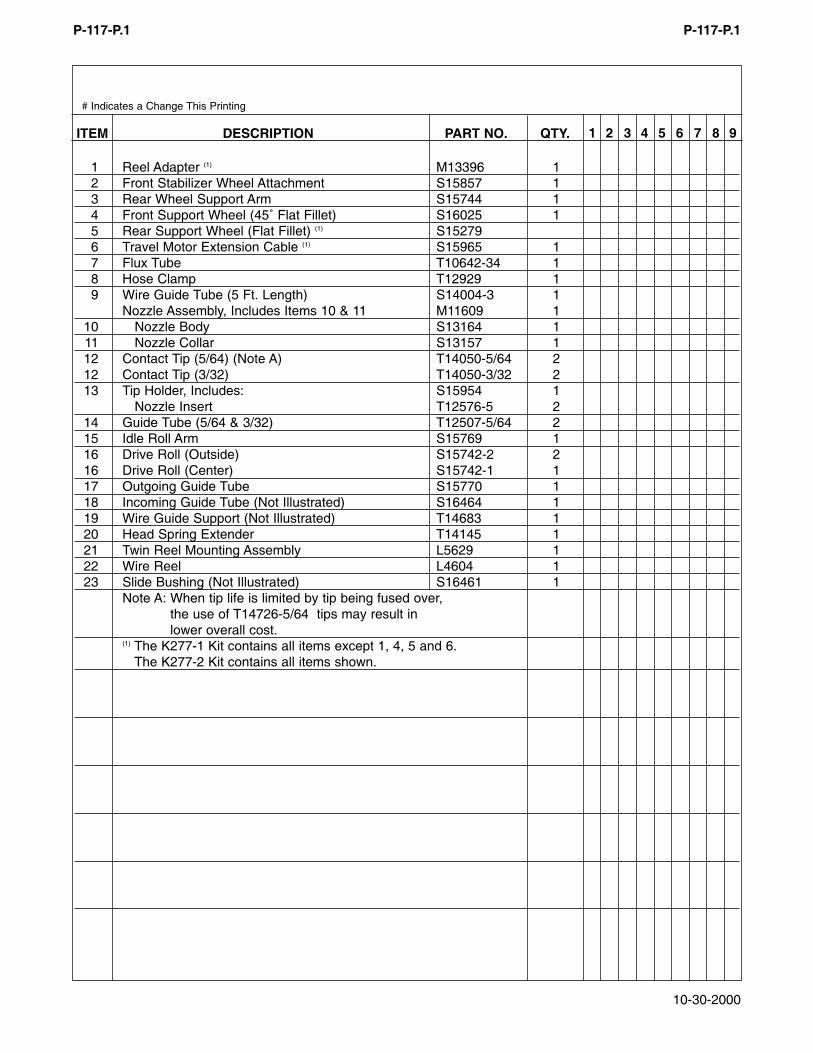
1 Reel Adapter (1) M13396 12 Front Stabilizer Wheel Attachment S15857 13 Rear Wheel Support Arm S15744 14 Front Support Wheel (45˚ Flat Fillet) S16025 15 Rear Support Wheel (Flat Fillet) (1) S152796 Travel Motor Extension Cable (1) S15965 17 Flux Tube T10642-34 18 Hose Clamp T12929 19 Wire Guide Tube (5 Ft. Length) S14004-3 1
Nozzle Assembly, Includes Items 10 & 11 M11609 110 Nozzle Body S13164 111 Nozzle Collar S13157 112 Contact Tip (5/64) (Note A) T14050-5/64 212 Contact Tip (3/32) T14050-3/32 213 Tip Holder, Includes: S15954 1
Nozzle Insert T12576-5 214 Guide Tube (5/64 & 3/32) T12507-5/64 215 Idle Roll Arm S15769 116 Drive Roll (Outside) S15742-2 216 Drive Roll (Center) S15742-1 117 Outgoing Guide Tube S15770 118 Incoming Guide Tube (Not Illustrated) S16464 119 Wire Guide Support (Not Illustrated) T14683 120 Head Spring Extender T14145 121 Twin Reel Mounting Assembly L5629 122 Wire Reel L4604 123 Slide Bushing (Not Illustrated) S16461 1
Note A: When tip life is limited by tip being fused over,the use of T14726-5/64 tips may result inlower overall cost.
(1) The K277-1 Kit contains all items except 1, 4, 5 and 6.The K277-2 Kit contains all items shown.
10-30-2000
ITEM DESCRIPTION PART NO. QTY. 1 2 3 4 5 6 7 8 9
P-117-P.1P-117-P.1
# Indicates a Change This Printing


Nozzle Assembly, Includes Items 110 thru 125 asappropriate for wire size specified K231* 1 X •
Nozzle Assembly, for LT34 ONLY, Includes Items110, 111, 118, 121 and 122; Order Items 119,120, 123, 124 and 125 separately for thedesired wire size M8241-1 2 • X
110 Nozzle Insulator S10493-1 1 X X111 Nozzle Body S10157 1 X X111A Roll Pin T9967-10 1 X X113A Cone Body Assembly, Includes: M8249 1 X •113B Flux Cone Plug S10138 1 X •113C Roll Pin T9967-30 1 X •114 Retaining Nut S10147 1 X •115 Flux Cone T10575 1 X •116 Locking Ferrule T10574 1 X •117 Thumb Screw T9078-1 1 X •118 Special Socket Head Screw T10570 1 X •119 Rubber Flux Tube (Not Shown) T10642-1 1 X •119 Rubber Flux Tube, LT34 Only (Not Shown) T10642-11 1 • X120 Steel Flux Tube (Not Shown) T6996-9 1 X •120 Steel Flux Tube, LT34 Only (Not Shown) S10487 1 • X121 Hex Head Screw - Lead to Nozzle 1/2-13 x 1.50 1 X X122 Hex Nut - Lead to Nozzle 1/2-13 1 X X123 Contact Tip - 7/32 Wire Size S10125-7/32 1 X X123 Contact Tip - 3/16 Wire size S10125-3/16 1 X X123 Contact Tip - 5/32 Wire Size S10125-5/32 1 X X123 Contact Tip - 1/8 Wire Size S10125-1/8 1 X X123 Contact Tip - 3/32 Wire Size; (3/8-24 Thread) Old Style S8087-3/32 1 X X123 Contact Tip - 3/32 Wire Size; (5/16-18 Thread) T14050-3/32 1 X X123 Contact Tip - 5/64 Wire Size; (3/8-24 Thread) Old Style S8087-5/64 1 X X123 Contact Tip - 5/64 Wire Size; (5/16-18 Thread)
See Note 1 T14050-5/64 1 X X124 Adapter for 3/32 and 5/64 S8087 Tips
(With 3/8-24 Female Thread) See Note 2 1 X X124 Adapter for 3/32 and 5/64 T14050 Tips
(With 5/16-18 Female Thread) S16844 1 X X125 Nozzle Insert for 3/32 and 5/64 Wire (For NA) S15106-3/32 1 X •125 Nozzle Insert for 5/64 Wire (For LAF & LT) S12773-3/32 1 X X
Mounting Clip (For Mounting Nozzle on LAF2) T10714 ø 2 X •Nozzle Extension (5.38” long) (For 3/32 & Larger Wire) S12003 As Req’d X •
* Specify Wire Size
Note 1 When tip life is limited by tip being fused over, theuse of T14726-5/64 Tips may result in a loweroverall cost.
Note 2 This adapter is no longer available, order AdapterS16844 and the appropriate T14050 Tips orT14726-5/64 Tip.
10-07-2002
Use only the parts marked “X” in the column under theheading number called for in the model index page.
ITEM DESCRIPTION PART NO. QTY. 1 2 3 4 5 6 7 8 9
P-101-M.1P-101-M.1
# Indicates a Change This Printing
#


Solid State Remote Field Control, Includes: K224 11 Top Door M10639-4 12 Terminal Strip S14530-1 1
Number Plate T10726-90 14 Capacitor S10593 15 Auto Transformer M12702 ø 16 Box Assembly M12706 ø 17 Transformer S15257 ø 18 Capacitor T11079 19 Nameplate M12688 1
10 Polarity Switch S13417 ø 111 Fuse Holder S10433 1
Fuse T10728-8 112 Capacitor S13490-1 113 Diode T12705-15 114 SCR and Heat Sink M13342 ø 115 Control P.C. Board (Code 7359 Only) L5316 115 Control P.C. Board (Code 7683 & Above) L5759-1 116 Caution Decal T13470 118 Choke S14644 119 Resistor (Code 7742 & Above) T12731-42F 1
K224 Mounting Angles S12995-1 & 1 eaS13709
01-28-2003
ITEM DESCRIPTION PART NO. QTY. 1 2 3 4 5 6 7 8 9
P-114-HP-114-H
# Indicates a Change This Printing
K224 SOLID-STATE REMOTE FIELD CONTROL(DISCONTINUED)
1 2 4 5 6
16
12
15
18 19 14 13
11
10
987
L529710-2-81Q
ø This part is obsolete and no longer available.
#


![1907.] Proceedings. 279](https://static.fdocuments.in/doc/165x107/61fb67f62e268c58cd5dca92/1907-proceedings-279.jpg)