K20316EN - Русклимат€¦ · with the objective of optimising the chiller operation on the...
52
K20316EN ed.1 TCAEY-THAEY 270÷2160 Y-Pack range Macrosystem 67÷161 kW 79÷175 kW Packaged air-cooled reversible water chillers and heat pumps with axial fans. Range with hermetic Scroll compressors and R410A refrigerant gas.
Transcript of K20316EN - Русклимат€¦ · with the objective of optimising the chiller operation on the...

K20316EN ed.1
TCAEY-THAEY 270÷2160
Y-Pack rangeMacrosystem67÷161 kW79÷175 kW
Packaged air-cooled reversible water chillers and heat pumps withaxial fans.Range with hermetic Scroll compressors and R410A refrigerant gas.


contents
3
Contents
General Features .......................................................................................................................................4 Intended C onditi ons of Use .......................................................................................................................4 New Y-Pack series ....................................................................................................................................5 Energy-savi ng, reliable and versatile water chillers and heat pumps .................................................5 AdaptiveFunction Plu s ............................................................................................................................6 TCAEBY TC AETY TC AESY TCAEQY THAET Y THAESY Models 270÷2160...............................8 Construction features ..................................................................................................................................8 Versions ........................................................................................................................................................8 Potential i nstallati ons ..................................................................................................................................8 Electrical board ............................................................................................................................................8 Accessories ................................................................................................................................................9 Factor y fitted accessories ..........................................................................................................................9 Accessories supplied l oose........................................................................................................................9 Technical dat a..........................................................................................................................................10 Energy efficiency at partial loads - ESEER index ................................................................................16 Electronic controls..................................................................................................................................17 Electronic contr ol .......................................................................................................................................17 KTR – Remote keyboard..........................................................................................................................17 Serial conn ection ....................................................................................................................................18 Serial connec tion .......................................................................................................................................18 Supervision.................................................................................................................................................18 KSC – Clock card ......................................................................................................................................18 Performance .............................................................................................................................................19 Choice of a chiller or heat pump and use of the perfor mance tabl es ...............................................19 Performance dat a....................................................................................................................................20 Pressure drop s ........................................................................................................................................28 Residual static pressure........................................................................................................................29 Power levels and sound pressure ......................................................................................................33 Operating limits .......................................................................................................................................34 Use of anti-freeze solutions..................................................................................................................34 RC100 and DS accessories: performances and pressur e drops ......................................................35 Dimensions and footprints...................................................................................................................40 Clearances and positioning .....................................................................................................................41 Handling and s torage................................................................................................................................41 Installation and connection to the system .............................................................................................41 TCAEBY – TCAETY – TCAESY – TCAEQY Weights .........................................................................42 THAETY – THAESY Weights ..................................................................................................................43 W ater connections..................................................................................................................................44 Maxi mum water circuit content................................................................................................................44 Water data ..................................................................................................................................................44 Expansion tank technical data.................................................................................................................44 W ater circuits ...........................................................................................................................................45 Electrical connections ...........................................................................................................................47

Y-PACK general features
4
General Features
Intended Conditions of Use The TCAEBY, TCAETY, TCAESY and TCAEQY units are packaged air-cool ed water chillers with axial fans , available in standard, high temperature/efficiency, sil enced and supersilenced versions respecti vel y. The THAET Y an THAESY units are packaged reversible air cooled heat pumps on the cooling cycle with axi al fans in the high temperature/efficiency and sil enced versions respecti vel y.
They ar e designed for use in air conditioning or industrial process sys tems that require cooled water (TCAEBY, TCAETY, TCAESY, TCAEQY) or heated and cool ed water (THAETY, THAESY), not water for human consumption. The units are designed for outdoor installation.
The units comply with the following directi ves: ○ Machiner y directive 98/37/EEC (MD); ○ Low voltage directi ve 2006/95/EEC (LVD); ○ Electromagnetic compatibility Directive 89/336/EEC (EMC); ○ Pressure equipment Directive 97/23/EEC (PED).
Guide to reading the cod e "SERIES" code "MODEL" code
T C A E B Y 2 70÷160
Standard T Cooling onl y
High temperature/efficiency
H S Silenced
Q
Water produc tion
unit
Heat pump
Air-cooled Scroll-type hermetic
compressors
Supersilenced
R410A refrigerant
fluid
No. compressors
Approxi mate cooling capacity
(in kW)
Potential in stallations: Standard: Installation without pump and without water buffer tank. Pump: P1 – Ins tallation with pump. P2 – Ins tallation with increased static pressur e pump. DP1 – Installation with double pump, incl uding an automaticall y ac tivated pump i n stand- by. DP2 – Installation with i ncreased s tatic pressure doubl e pump, incl uding an automaticall y acti vated pump in stand-by. Tank & Pump: ASP1 – Ins tallati on with pump and water buffer tank. ASP2 – Ins tallati on with increased static pressure pump and water buffer tank. ASDP1 – Installation with doubl e pump, incl uding an automaticall y ac tivated pump in stand-by and water buffer tank. ASDP2 – Installation with i ncreased s tatic pressure doubl e pump, i ncluding an automaticall y acti vated pump in stand-by and water buf fer tank. Example: TCAEQY 290 ASP1 ○ Water production unit ○ Cooling onl y; ○ Air cooled; ○ With 2 x hermetic scroll compr essors; ○ Supersilenced unit; ○ With R410A refrigerant fluid; ○ Nominal cooling capacity of approxi mately 90 kW; ○ Installation with pump and water buffer tank.

Y-PACK general features
5
New Y-Pack series Energy-saving, reliable and versatile water chillers and
heat pumps A comp lete, flexible range, with three shutter step s New water chillers and heat pumps, from 70 to 160 kW, in R410A with two scroll compressors of different powers (where envisaged) installed on the same refrigerant circuit to obtain three cooling and heating capacity steps, thus allowing for greater regulation fl exibility and greater efficiency when operating at partial l oads compared to a chiller unit equipped with a tr aditional tandem. T he efficiency of these units is also boos ted by the innovative AdaptiveFunction Plu s control logic, with which the range is equipped. This l ogic, developed by RHOSS i n partnership with the Uni versity of Padua, optimises compr essor activation and their operating cycles, as well as making it possibl e to obtain opti mum comfort levels i n all wor king conditi ons and the best perfor mances in ter ms of energy efficiency during seasonal operati on. LOW ENERGY CONSUMPTION water chillers and heat pumps The AdaptiveFunction Plu s “Economy” function combines comfort with l ow energy consumption. In fact, by adjusti ng the set-point value, it opti mises compressor operation on the basis of the actual wor king conditi ons. It is thus possible to achi eve significant seasonal energy savi ngs compared to water chillers and heat pumps of an equivalent power with traditional control logic. HIGH PRECISION water chil lers and h eat pumps By using the AdaptiveFunction Plus “Precision” function, it is possi ble to achieve as littl e fluctuation as possibl e, at partial capacities , in terms of the average Set-point water temperatur e delivered to the users. Guaranteed reliabil it y, even with water in the pipes only Thanks to the “Virtual T ank” functi on, Y-Pack units with AdaptiveFunction Plu s can operate i n systems with a low water content of down to 2 litres/kW, even without the presence of a water buffer tank, whilst s till guaranteei ng the reliability of the units over ti me and the good wor king order of the system. Estimation of the syst em's thermal inertia Y-Pack units with Ad aptiveFunction Plus are able to esti mate the characteristics of the thermal i nertia that regulates the system dynamics. T his is possi ble thanks to the " ACM Autotuning” functi on, which processes the information relating to the progress of the water temperatures, identifying the opti mal value of the control parameters. Continuous system autodiagnosis The es timation function is al ways acti ve and makes it possibl e to adapt the contr ol par ameters quickl y to every change in the water circuit and thus i n the system water contents. Silent operation (VERSIONS T, S and Q) Thanks to the 3 or 2 shutter steps and the condensation control, installed as standard on all T, S and Q units, the noise level is also reduced at partial loads. For example, during night operation, when the load is reduced but sensiti vity to noise is at its peak, the control r educes the number of fan revol utions, the primar y noise source in this type of unit, producing obvious benefits in terms of acoustic well-being.

Y-PACK general features
6
AdaptiveFunction Plus The new adapti ve regul ation logic, Ad aptiveFunction Plus, is an excl usive RHOSS patent and the result of a long partnershi p with the University of Padua. The various algorithm pr ocessing and devel opment operations were i mplemented and tes ted on units in the Y-PACK range in the RHOSS S.p.A. Research&D evelopment Laborator y by means of numerous test campaigns. Objectives • To guarantee optimal unit operation in the sys tem in which it is installed. Evolved adaptive logic. • To obtain the best possibl e performance from a water chiller and a heat pump in terms of energy efficiency at full and partial loads. Low consumption chiller. Operating logic In general, the actual control logics on water chillers/heat pumps do not consider the characteristics of the sys tem in which the units are installed; they usuall y regul ate the return water temperature and are positioned so as to ensure the operation of the chillers, givi ng less priority to the sys tem requirements. The new AdaptiveFunction Plu s adapti ve logic counters these logics with the objecti ve of optimising the chiller operation on the basis of the system char acteristics and the effecti ve thermal load. T he contr oller regulates the deli ver y water temperature and adjusts itself, as and when required, to the relative oper ating conditions usi ng: • the i nfor mation contained in the return and deli ver y water temperature to estimate the wor king conditions thanks to a certain mathematical for mula;
• a special adapti ve algorithm that uses this esti mate to vary the val ues and the start-up and switch- off limit values of the compressors; the opti mised compressor start-up management guar antees a pr ecision water suppl y to the user, reduci ng the fluctuati on around the set- point val ue. Main functions Efficiency or Precision Thanks to the evolved control, it is possibl e to run the chiller on two different regulation setti ngs to obtain the bes t possible performance in terms of energ y efficiency and considerable seasonal savings, or high water delivery temperature precision: 1. Low consumption chiller: Economy” option
It is well known that chillers wor k at full capacity for j ust a ver y small percentage of their operating time, while they wor k at partial capacity for most of the season. Therefore, the power they need to supply generally differs from the nominal design power, and oper ation at partial capacity has a noticeable effec t on seasonal energy perfor mance and consumpti on. This makes it necessar y to run the unit so that it is as efficient as possible at partial capacity. T he contr oller therefore ensures that the water delivery temperature is as high as possible ( when operating as a chiller) or as l ow as possibl e (when operating as a heat pump) whilst compati ble with the thermal loads, meani ng that it is on a sliding scale, unlike in traditi onal systems. T his prevents energy wastage linked to the mai ntenance of pointlessl y onerous temperature l evels for the chiller, ensuring that the rati o between the power to be supplied and the energy to be used to produce it is always at an optimum level. Fi nall y the right level of comfort is availabl e to everyone!
Summer season: the Y-Pack unit, with three shutter steps, offers seasonal energy savings of around 33% when compared to a mono-compressor unit ( wher e envisaged) and around 18% when compared to a standard bi-compressor unit.
Y
200400600800
10001200140016001800200022002400
0
X4 5 6 7 8 9 10
X Year divi ded into months (1 Januar y, 2 Februar y, etc.).
Y Energy consumption ( kWh).
Mono-compressor unit with fi xed set-point.
Bi-compressor unit, 2 shutter steps with fixed set-point.
Bi-compressor Compact-Y unit, 3 shutter steps with scrolling set-point.
W inter season: the Y-Pack unit, with three shutter steps, offers seasonal energy savings of around 41% compared to a mono-compressor unit ( wher e envisaged), and ar ound 36% when compared to a s tandard bi-compressor unit. Calculations demonstr ate that its seasonal consumption is equi valent to that of a CL ASS A machine.
Y
600120018002400300036004200480054006000660072007800
0
X9 10 11 12 1 2 3 4
X Year divi ded into months (1 Januar y, 2 Februar y, etc.).
Y Energy consumption ( kWh).
Mono-compressor unit with fi xed set-point .
Bi-compressor unit, 2 shutter steps with fixed set-point.
Bi-compressor Compact-Y unit, 3 shutter steps with scr olling set-poi nt.
Annual: efficiency over the annual operation of the unit i n heat pump mode. Ad aptiveFunction Plus, with the “Economy” functi on, enabl es the chiller assembl y to operate energy-saving programmes whilst s till providing the required level of comfort.
Y
2,000
2,500
3,000
3,500
4,000
4,500
5,000
X1 2 3 4 5 6 7 8 9 10 11 12
X Year divi ded into months (1 Januar y, 2 Februar y, etc.).
Y Energy efficiency kWh supplied / kWh absorbed.
Bi-compressor Compact-Y unit, 3 shutter steps with scr olling set-poi nt.
Bi-compressor unit, 2 shutter steps with fixed set-point.
Mono-compressor unit with fi xed set-point .
Analysis conducted in an office building in Milan, comparing the operation of: • a mono-compressor reversible heat pump, which operates with a fixed set-point (7°C in the summer and 45°C in the winter); • a reversible heat pump unit w ith two compressors, of equal power, operating on the same refrigerant circuit and working with a fixed set-point (7°C in the summer an d 45°C in the winter); • a Compact-Y unit w ith three shutter steps and AdaptiveFunction Plus logic, which operates w ith a scrolling set-point (range between 7 and 14 °C in the summer, ra nge between 35 and 45°C in the w inter).

Y-PACK general features
7
2. High precision: “Precision” option
In this operating mode, the unit wor ks at a fi xed set-point and, thanks to the delivery water temper ature control and the evolved r egulation logic, at a capacity of between 50% and 100% it is possible to guar antee an aver age fluctuati on from the water suppl y temperature of approximatel y ± 1.5°C from the set-point value compared to an average fluctuation over ti me of approximatel y ± 3°C, which is normall y obtained with s tandar d return control. The “Precision” option thus guarantees precision and reliability for all those applicati ons that require a regulator that guar antees a more accur ate constant water supply temperature, and wher e there are particular damp contr ol requirements . However, in process applications it is always advisable to use a water buffer tank or a greater system water content to guarantee higher system ther mal inertia.
FC
s
s Fluctuati on FC Load
Unit with water buffer tank, 4 litres/kW i n the sys tem and return control.
Unit with water buffer tank, 2 litres/kW i n the sys tem and deliver y control with “Precision” AdaptiveFunction Plu s function
The chart illustrates the fluctuations of the water temperature from the set value for the various capacities, demonstrating how a unit w ith delivery control and the AdaptiveFunc tion Plus “Precision” function guarantees greater water supply temperature precision Virtual Tank: guaranteed reliability, even with water in the pipes only A low water content in the system can cause the chiller units /heat pumps to be unreliable and can generate system instability and l ack of perfor mance. Thanks to the Virtual Tank function, this is no longer a problem. T he unit can operate in systems with just 2 litres/kW in the pipes given that the control is able to compensate for the l ack of inerti a specific to a water buffer tank, " muffling" the control signal, preventing the compressor from switchi ng on and off in an unti mel y fashi on and reducing the average fl uctuation of the set-poi nt value.
t
T
20000
2
4
6
8
10
12
14
3000 4000 5000 6000 7000 8000 9000
T1
T Water temperature (°C) t Time (s)
T1 Set-point temper ature
Deliver y temperature with Virtual Tank
Deliver y temperature without Virtual Tank
The chart shows the various chiller outlet temperatures considering capacity of 80%. We can observe how the temperatures of the unit with AdaptiveFunction Plus l ogic and the Virtual Tank function is far less varied and more stable over time, w ith average temperatures closer to the working set-point compared to a unit without the Virtual Tank function. Moreover, we can see how the unit w ith AdaptiveFunction Plus logic and the Virtual Tank function sw itches the compressor on less often over the same period of time, w ith obvious advantages in terms of energy consumption and system reliability. ACM Autotuning compressor management AdaptiveFunction Plu s enables the Y-Pack units to adapt to the system they are ser ving, so as to al ways identify the best compressor operating parameters in the different worki ng conditions . During the initi al operating phases, the special “Autotuning” functi on enables the Y-Pack unit with Ad aptiveFunction Plus to estimate the ther mal inertia characteristics that regulate the sys tem dynamics. T he func tion, which is automaticall y acti vated when the unit is switched on for the first ti me, executes a number of set oper ating cycles, during which it processes the information r elati ve to the water temperatures. I t is thus possible to esti mate the physical charac teristics of the system and to identify the opti mal val ue of the par ameters to be used for the control. At the end of this initi al auto-es timate phase, the “Autotuning” func tion r emains acti ve, making it possible to adapt the control parameters quickl y to ever y change in the water circuit and thus in the system water contents.

Y-PACK construction features
8
TCAEBY TCAETY TCAESY TCAEQY THAETY THAESY Models 270÷2160
Construction features ○ Load-bearing structure and panels in galvanised and painted (RAL 9018) sheet s teel; base in gal vanised sheet s teel. ○ The struc ture consists of 2 sec tions : • sound-proofed technical compartment for housi ng the compressors, the electrical panel and the main components i n the refrigerant circuit. • aeraulic compartment for housing the heat exchange coils, the plate heat exchangers, the motor-driven fans and the pump assembly accessories (if present). ○ Hermetic, Scroll-type r otar y compressors, complete with internal thermal protection and crankcase heater acti vated automaticall y when the unit s tops (as long as the power suppl y to the unit is preser ved). ○ Adequatel y insulated, braze-welded pl ate water side heat exchange i n stainless steel. ○ Air side heat exchanger comprised of a coil of copper pipes and aluminium fi ns. ○ Motor-driven axial fans with external rotor, equipped with inter nal ther mal pr otecti on and complete with a single row of pr otecti on grilles for version B and a double row for versions T, S and Q. ○ Proportional electronic device for the pressurised and continuous regulation of the fan rotati on speed down to an external air temperature of -10°C when operating as a chiller and up to an external air temperature of 40°C when operating as a heat pump ( as standard i n versions T, S and Q). ○ Victaulic type water connections. ○ Differential pressur e switch that protects the unit from any i nterruptions to the water flow. ○ Single refrigerant circuit made from annealed copper pi pe (EN 12735- 1-2) complete with: cartridge dr yer filter, pr essure connections, manual reset safety pressure switch on the high pressure side, automatic reset safety pressure switch on l ow pressure side, safety val ve(s), filter shut-off val ves, thermostatic expansion val ve ( 1 for TCAEBY, TCAETY,TCAESY and TCAEQY and 3 for THAETY THAESY) , cycle inversion val ve (for THAETY-THAESY), liquid recei ver (for THAETY-THAESY) and stop val ves (2 for THAETY-THAESY), liquid indicator, compressor aspirated gas separator and solenoid val ve on the liquid line (for THAETY-THAESY) and i nsulation of the aspiration line. ○ Unit with IP24 level of protec tion. ○ Compatible control, with AdaptiveFunction Plu s function. ○ The unit is complete with the R410A refrigerant charge. ○ Ductabl e condensation drain (for THAETY-THAESY).
Versions
B – Standard chiller onl y version (TCAEBY). T – High temperatur e/high efficiency version, with l arger coil surface (TCAETY-THAETY). S - Silenced version complete with soundproofed compressors, l ower fan speed and larger coil surface (TCAESY-THAESY). The fan speed is automatically i ncreased with the exter nal temperature i ncreases considerabl y. Q - Supersilenced version complete with soundproofed compressors, l ower fan speed and larger coil surface (TCAEQY). The fan speed is automaticall y increased with the external temperature increases consi derably.
Potential installations Standard: Installation without pump and without water buffer tank. Pump: P1 – Ins tallation with pump. P2 – Ins tallation with increased static pressur e pump. DP1 – Installation with double pump, incl uding an automaticall y ac tivated pump in stand-by. DP2 – Installation with i ncreased s tatic pressure double pump, incl uding an automaticall y ac tivated pump i n stand- by. The pump assembl y also comes complete with: expansion tank, safety val ve and water side pressure gauge. In the case of an i ndi vidual pump, the assembl y also comes complete with a deli ver y shut- off val ve. In the case of a double pump, the assembl y also comes complete with a non-return val ve and one aspiration valve for each pump. Tank & Pump: ASP1 – Ins tallati on with pump and water buffer tank. ASP2 – Ins tallati on with increased static pressure pump and water buffer tank. ASDP1 – Installation with doubl e pump, including an automaticall y ac tivated pump i n stand-by and water buffer tank. ASDP2 – Installation with i ncreased s tatic pressure double pump, incl uding an automaticall y ac tivated pump i n stand- by and water buffer tank. In addition to that supplied with the pump accessor y, the assembl y also includes: inertial water buffer tank in deli ver y (250 l for models 270÷2160 version B, 250 l for models 270÷2100 versions T, S and Q, 450 l for models 2115÷2160 versions T, S and Q), air bleed val ve, water drai nage valve and elec tric heater connection.
Electrical board
○ Electrical board accessibl e by openi ng the front panel, conforming with current IEC norms, can be opened and closed with a suitable tool. ○ Compl ete with: • electrical wiring arranged for power suppl y 400-3ph+N-50Hz; • auxiliary power suppl y 230V-1ph-50Hz drawn from the main power supply; • control power supply 24V-1ph-50Hz drawn from the main power suppl y; • general isolator, complete with door interlocking isolator; • automatic thermal overload switch to protec t the compressors and the motor-driven fans; • protecti on fuse for the auxiliary circuit; • power contactor for the compressors; • remote machine controls: remote ON/OFF, summer/winter selec tor; • remote machine controls: compressor operating light, general lock light; ○ Programmable elec tronic boar d with microprocessor, controlled by the keyboard inserted in the machine. ○ This electronic board performs the following functi ons: • regulation and management of the set points for unit outlet water temper ature; cycle inversion (THAETY-THAESY); safety timer delays; circulating pump; compressor and system pump hour-run meter; pressurised defrost cycles; electronic anti-freeze protecti on which cuts in automaticall y when the machine is switched off; and the functions which control the operation of the indi vi dual parts making up the machine; • complete protection of the unit, automatic emergency shutdown and display of the alarms which have been acti vated; • compressor pr otecti on phase sequence monitor; • unit protection against low or high phase power suppl y voltage; • display of the programmed set-points on the display; of the water i n/out temper atures on the display; of the condensation and condensation/evaporation pressures (THAETY-THAESY); of the electrical voltage values in the three phases of the elec trical circuit that powers the unit; of the al arms on the displ ay; of the chiller or heat pump function on the display (THAETY-THAESY); • user interface menu; • automatic pump oper ating time balance (DP1-DP2, ASDP1- ASDP2 i nstallations);

Y-PACK accessories
9
• automatic ac tivation of the pump i n standby in the event of an alar m (DP1-DP2, ASD P1- ASDP2 i nstallations); • display of the heat recover y/desuperheater inlet water temperature; • alarm code and description; • alarm histor y management (menu protected by manufacturer password). ○ The followi ng is memorized for each alarm: • date and time of intervention (if the KSC accessor y is present); • inlet/outlet water temperatur es when the alarm inter vened; • the condensation pressure values at the time of the alar m, if the FI10 accessor y is present for TCAEBY models and always for versions T, S and Q. • alarm delay time from the switch-on of the connected device; • compressor status at moment of alarm; ○ Advanced functions: • Hi-Pressure Prevent with forced cooling capacity shuttering for high external temperatures (during summer operati on), • configured for serial connec tion (KR S485, KFTT10, KRS232 and KUSB accessor y); • possibility to have a digital input for remote management of the double set point (contact RHOSS S.p.A. pre-sales ). • possibility to have an analogue input for the scrolling set-point vi a a 4-20mA remote signal (contact RHOSS S.p.A. pre-sales ); • configured for management of ti me bands and operation parameters with the possibility of daily/weekl y operating programs (KSC accessor y); • check-up and monitoring of scheduled maintenance status ; • testing of the units assisted by computer; • self-diagnosis with continuous monitoring of the func tioni ng of the unit . ○ Set-point regulation via the Ad aptive Function Plus with two opti ons: • fixed set-poi nt (Precision options); • scrolling set-point (Economy opti on). Accessories
Factory fitted accessories P1 – Ins tallation with pump. P2 – Ins tallation with increased static pressur e pump. DP1 – Installation with double pump, incl uding an automaticall y ac tivated pump in stand-by. DP2 – Installation with i ncreased s tatic pressure double pump, incl uding an automaticall y ac tivated pump i n stand- by. ASP1 – Ins tallati on with pump and water buffer tank. ASP2 – Ins tallati on with increased static pressure pump and water buffer tank. ASDP1 – Installation with doubl e pump, including an automaticall y ac tivated pump i n stand-by and water buffer tank. ASDP2 – Installation with i ncreased s tatic pressure double pump, incl uding an automaticall y ac tivated pump i n stand- by and water buffer tank.
FI10 – Modulated condensati on contr ol for continuous operation, as chiller down to an external temperature of -10°C (for TCAEBY models onl y). RA - Evaporator antifreeze electric heater to prevent the risk of ice formation inside the exchanger when the machine is switched off (as long as the unit is not disconnected from the power suppl y) RDR – Antifreeze electric heater for desuperheater / heat recover y (DS or RC100), to prevent the risk of ice formation inside the recover y exchanger when the machine is switched off ( as long is the unit is not disconnected from the power suppl y). RAS – 300W antifreeze electric heater for water buffer tank (available for ASP1-ASDP1- ASP2-ASDP2 i nstallations); to prevent the risk of ice formation in the water buffer tank when the machine is switched off (as long as the unit is not disconnec ted from the power supply). RAE 1 – 27W antifreeze electric heater for motor-driven pump (availabl e for P1-DP1-ASP1-ASDP1 installations); to prevent the water contai ned in the pump from freezing when the machine is switched off (as long as the unit is not disconnected fr om the power suppl y). RAE 2 – 27W antifreeze electric heater for double motor-driven pumps (available for P2-DP2-ASP2-ASDP2 installations); to prevent the water contai ned in the pumps from freezing when the machine is switched off (as long as the unit is not disconnected fr om the power suppl y). DS – Desuperheater. RC100 – Heat recover y with 100% recover y; the accessory comes complete with condensation control FI10 (as standard in versions T, S and Q) and a differential pr essure switch on the recover y exchanger. It is not active as a heat pump during operation. GM – Refrigerant circuit high and low pressure gauges. SFS – Soft-start device for reducing the s tart-up current during the start-up phase ( weight 40 Kg). FTT10 – FTT10 serial interface card for connection to super vision systems (LonWor ks® system compliant with Lonmar k® 8090-10 protocol with chiller profile). SS – RS485 serial interface card to create dialogue networks between cards (maximum of 200 units at a maxi mum distance of 1000 m) and the building automation, external super vision systems or RHOSS S.p.A. super vision systems (protocols supported: proprietary protocol;Modbus® RTU). CR - Power factor correction capacitors (cosΦ > 0.91). EEV – Elec tronic ther mostatic val ve. RAP - Unit with copper/pre-painted aluminium coils. BRR - Unit with copper/copper coils. RRS - Unit with copper/tin-plated copper coils. DSP – D oubl e set-point via digital consensus (incompatibl e with the CS accessor y). CS – Scrolling set point vi a analogue signal 4-20 mA (incompati ble with the DSP accessor y). On the basis of the required val ues, it could be necessary to install the EEV accessor y too. RPB - Coil protecti on networks with acci dent prevention function (to be used as an alternative to the FMB accessory). FMB - Mechanical filters to protect the coils, with l eaf protection function (to be used as an alternative to the RPB accessor y).
Accessories supplied loose
KSA - Rubber anti-vibration mountings. KSC - Clock card to display date/time and to regulate the machine with dail y/weekl y start/stop ti me bands, with the possi bility to change the set- points . KTR - Remote keypad for control at a distance with r ear illumi nated LCD display (same functi ons as the one built into the machine). KISI – CAN bus serial interface (Controller Area Network compatible with evol ved hydronic system for integrated comfort management (protocol supported C anOpen®). KRS232 – RS485/RS232 serial converter for interconnec tion between RS485 serial networ k and super vision systems with serial connec tion to PC via RS232 serial port (RS232 cable provided). KUSB – RS485/USB serial converter for interconnec tion between RS485 serial networ k and super vision systems with serial connec tion to PC via USB port (USB cable pr ovided). KMDM – GSM 900-1800 modem kit to be connected to the unit for the management of the parameters and any alar m signals on a remote basis. T he kit consists of a GSM modem with rel ati ve RS232 car d. It is necessary to purchase a SIM data card, not supplied by RHOSS S.p.A. KRS – RHOSS S.p.A. super vision software for the i nstallati on and remote management of the units. T he kit consists of a CD-Rom and hardware key.

TCAEBY 270÷2160 technical data
10
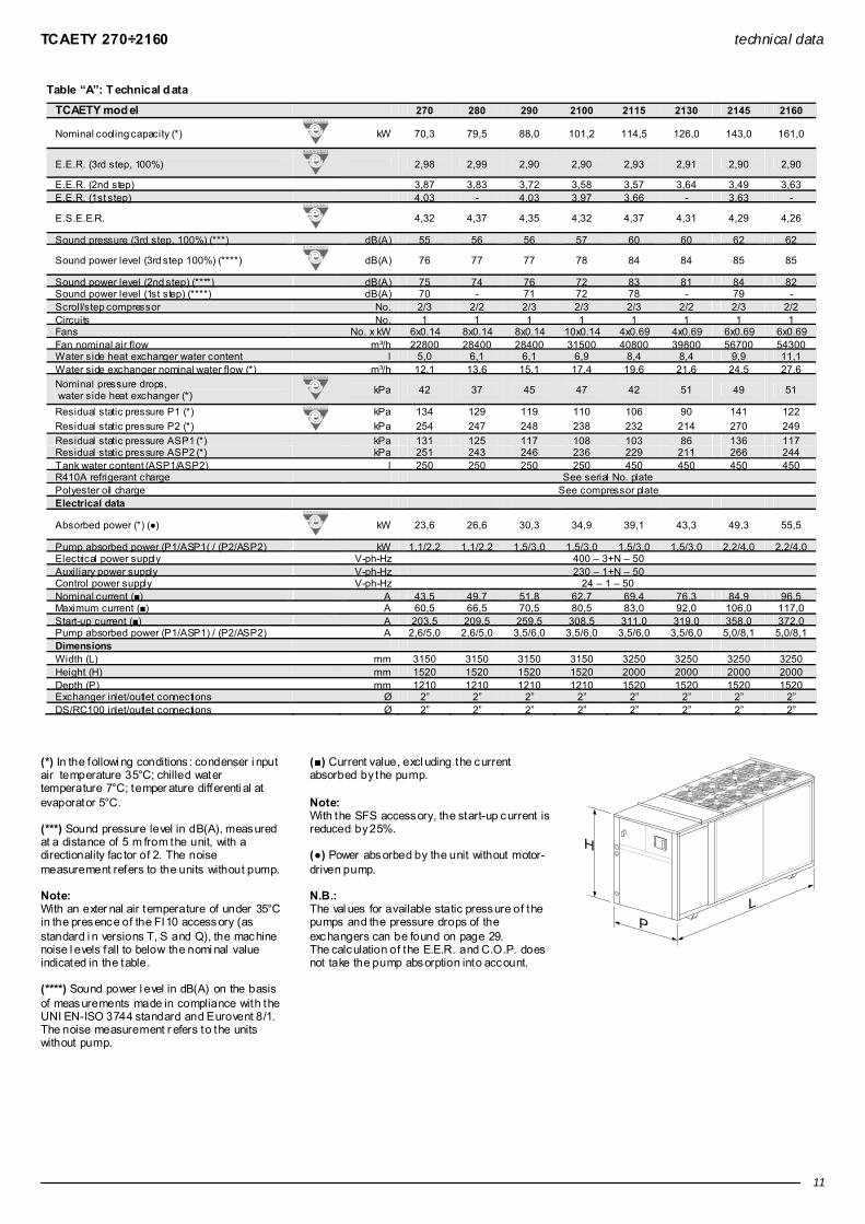
Technical data Table “A”: Technical dat a
TCAEBY model 270 280 290 2100 2115 2130 2145 2160
Nominal cooling capacity (*)
kW 67,5 75,3 83,0 96,0 110,5 120,5 138,5 155,0
E.E.R. (3rd step, 100%)
2,65 2,69 2,56 2,69 2,72 2,64 2,66 2,61
E.E.R. (2nd step) 3,44 3,59 3,41 3,36 3,28 3,34 3,33 3,26 E.E.R. (1st step) 3,58 - 3,71 3,74 3,36 - 3,50 -
E.S.E.E.R.
3,96 3,95 3,92 4,01 4,06 3,96 3,94 3,87
Sound pressure (3rd step, 100%) (***) dB(A) 60 60 60 62 68 68 68 69
Sound power level (3rd step 100%) (****)
dB(A) 82 82 82 84 90 90 90 91
Sound power level (2nd step) (****) dB(A) 81 79 81 83 88 87 88 88 Sound power level (1st step) (****) dB(A) 76 - 76 78 83 - 83 - Scroll/step compressor No. 2/3 2/2 2/3 2/3 2/3 2/2 2/3 2/2 Circuits No. 1 1 1 1 1 1 1 1 Fans No. x kW 2x0.69 2x0.69 2x0.69 3x0.69 2x2.00 2x2.00 2x2.00 3x2.00 Fan nominal air flow m³/h 20800 20400 20200 30600 41200 41000 40000 58800 Water side heat exchanger water content l 5,0 6,1 6,1 6,9 8,4 8,4 9,9 11,1 Water side exchanger nominal water flow (*) m³/h 11,6 12,9 14,5 16,5 19,0 20,7 23,8 26,6 Nominal pressure drops, water side heat exchanger (*)
kPa 40 35 41 44 41 47 46 48
Residual static pressure P1 (*) kPa 139 137 125 116 110 97 148 131 Residual static pressure P2 (*) kPa 260 255 255 244 236 223 278 259 Residual static pressure ASP1 (*) kPa 137 133 124 114 108 94 144 126 Residual static pressure ASP2 (*) kPa 257 252 253 242 234 219 274 254 Tank water content (ASP1/ASP2) l 250 250 250 250 250 250 250 250 R410A refrigerant charge See serial No. plate Polyester oil charge See compressor plate Electrical data
Absorbed power (*) (●)
kW 25,5 28,0 32,4 35,7 40,6 45,6 52,1 59,4
Pump absorbed power (P1/ASP1( / (P2/ASP2) kW 1,1/2,2 1,1/2,2 1,5/3,0 1,5/3,0 1,5/3,0 1,5/3,0 2,2/4,0 2,2/4,0 Electrical power supply V-ph-Hz 400 – 3+N – 50 Auxiliary power supply V-ph-Hz 230 – 1+N – 50 Control power supply V-ph-Hz 24 – 1 – 50 Nominal current (■) A 47,0 52,3 55,4 64,1 71,9 80,3 89,7 103,1 Maximum current (■) A 58,0 62,5 66,5 76,0 88,0 97,0 110,0 117,0 Start-up current (■) A 201,0 205,5 255,5 304,0 316,0 324,0 362,0 380,0 Pump absorbed power (P1/ASP1) / (P2/ASP2) A 2,6/5,0 2,6/5,0 3,5/6,0 3,5/6,0 3,5/6,0 3,5/6,0 5,3/8,1 5,3/8,1 Dimensions Width (L) mm 2650 2650 2650 3150 3150 3150 3150 3450 Height (H) mm 1700 1700 1700 1700 1730 1730 1730 1730 Depth (P) mm 1210 1210 1210 1210 1210 1210 1210 1210 Exchanger inlet/outlet connections Ø 2” 2” 2” 2” 2” 2” 2” 2” DS/RC100 inlet/outlet connections Ø 2” 2” 2” 2” 2” 2” 2” 2”
(*) In the followi ng conditions : condenser i nput air temperature 35°C; chilled water temperature 7°C; temper ature differenti al at evaporator 5°C. (***) Sound pressure level in dB(A), measured at a distance of 5 m from the unit, with a directionality fac tor of 2. The noise measurement refers to the units without pump. Note: With an exter nal air temperature of under 35°C in the presence of the FI10 accessory (as standard i n versions T, S and Q), the machine noise l evels fall to below the nomi nal value indicated in the table. (****) Sound power l evel in dB(A) on the basis of measurements made in compliance with the UNI EN-ISO 3744 standard and Eurovent 8/1. The noise measurement r efers to the units without pump.
(■) Current value, excl uding the current absorbed by the pump. Note: With the SFS accessory, the start-up current is reduced by 25%. (●) Power absorbed by the unit without motor-driven pump. N.B.: The val ues for available static pressure of the pumps and the pressure drops of the exchangers can be found on page 29. The calculation of the E.E.R. and C.O.P. does not take the pump absorption into account.
H
PL
TCAETY 270÷2160 technical data
11
Table “A”: T echnical d ata
TCAETY mod el 270 280 290 2100 2115 2130 2145 2160
Nominal cooling capacity (*)
kW 70,3 79,5 88,0 101,2 114,5 126,0 143,0 161,0
E.E.R. (3rd step, 100%)
2,98 2,99 2,90 2,90 2,93 2,91 2,90 2,90
E.E.R. (2nd step) 3,87 3,83 3,72 3,58 3,57 3,64 3,49 3,63 E.E.R. (1st step) 4,03 - 4,03 3,97 3,66 - 3,63 -
E.S.E.E.R.
4,32 4,37 4,35 4,32 4,37 4,31 4,29 4,26
Sound pressure (3rd step, 100%) (***) dB(A) 55 56 56 57 60 60 62 62
Sound power level (3rd step 100%) (****)
dB(A) 76 77 77 78 84 84 85 85
Sound power level (2nd step) (****) dB(A) 75 74 76 72 83 81 84 82 Sound power level (1st step) (****) dB(A) 70 - 71 72 78 - 79 - Scroll/step compressor No. 2/3 2/2 2/3 2/3 2/3 2/2 2/3 2/2 Circuits No. 1 1 1 1 1 1 1 1 Fans No. x kW 6x0.14 8x0.14 8x0.14 10x0.14 4x0.69 4x0.69 6x0.69 6x0.69 Fan nominal air flow m³/h 22800 28400 28400 31500 40800 39800 56700 54300 Water side heat exchanger water content l 5,0 6,1 6,1 6,9 8,4 8,4 9,9 11,1 Water side exchanger nominal water flow (*) m³/h 12,1 13,6 15,1 17,4 19,6 21,6 24,5 27,6 Nominal pressure drops, water side heat exchanger (*)
kPa 42 37 45 47 42 51 49 51
Residual static pressure P1 (*) kPa 134 129 119 110 106 90 141 122 Residual static pressure P2 (*) kPa 254 247 248 238 232 214 270 249 Residual static pressure ASP1 (*) kPa 131 125 117 108 103 86 136 117 Residual static pressure ASP2 (*) kPa 251 243 246 236 229 211 266 244 Tank water content (ASP1/ASP2) l 250 250 250 250 450 450 450 450 R410A refrigerant charge See serial No. plate Polyester oil charge See compressor plate Electrical data
Absorbed power (*) (●)
kW 23,6 26,6 30,3 34,9 39,1 43,3 49,3 55,5
Pump absorbed power (P1/ASP1( / (P2/ASP2) kW 1,1/2,2 1,1/2,2 1,5/3,0 1,5/3,0 1,5/3,0 1,5/3,0 2,2/4,0 2,2/4,0 Electrical power supply V-ph-Hz 400 – 3+N – 50 Auxiliary power supply V-ph-Hz 230 – 1+N – 50 Control power supply V-ph-Hz 24 – 1 – 50 Nominal current (■) A 43,5 49,7 51,8 62,7 69,4 76,3 84,9 96,5 Maximum current (■) A 60,5 66,5 70,5 80,5 83,0 92,0 106,0 117,0 Start-up current (■) A 203,5 209,5 259,5 308,5 311,0 319,0 358,0 372,0 Pump absorbed power (P1/ASP1) / (P2/ASP2) A 2,6/5,0 2,6/5,0 3,5/6,0 3,5/6,0 3,5/6,0 3,5/6,0 5,0/8,1 5,0/8,1 Dimensions Width (L) mm 3150 3150 3150 3150 3250 3250 3250 3250 Height (H) mm 1520 1520 1520 1520 2000 2000 2000 2000 Depth (P) mm 1210 1210 1210 1210 1520 1520 1520 1520 Exchanger inlet/outlet connections Ø 2” 2” 2” 2” 2” 2” 2” 2” DS/RC100 inlet/outlet connections Ø 2” 2” 2” 2” 2” 2” 2” 2”
(*) In the followi ng conditions : condenser i nput air temperature 35°C; chilled water temperature 7°C; temper ature differenti al at evaporator 5°C. (***) Sound pressure level in dB(A), measured at a distance of 5 m from the unit, with a directionality fac tor of 2. The noise measurement refers to the units without pump. Note: With an exter nal air temperature of under 35°C in the presence of the FI10 accessory (as standard i n versions T, S and Q), the machine noise l evels fall to below the nomi nal value indicated in the table. (****) Sound power l evel in dB(A) on the basis of measurements made in compliance with the UNI EN-ISO 3744 standard and Eurovent 8/1. The noise measurement r efers to the units without pump.
(■) Current value, excl uding the current absorbed by the pump. Note: With the SFS accessory, the start-up current is reduced by 25%. (●) Power absorbed by the unit without motor-driven pump. N.B.: The val ues for available static pressure of the pumps and the pressure drops of the exchangers can be found on page 29. The calculation of the E.E.R. and C.O.P. does not take the pump absorption into account.
H
PL

TCAESY 270÷2160 technical data
12
Table “A”: T echnical d ata
TCAESY model 270 280 290 2100 2115 2130 2145 2160
Nominal cooling capacity (*)
kW 70,3 79,5 88,0 101,2 108,0 119,0 136,0 151,0
E.E.R. (3rd step, 100%)
2,98 2,99 2,90 2,90 2,67 2,67 2,63 2,60
E.E.R. (2nd step) 3,87 3,83 3,72 3,58 3,47 3,56 3,33 3,51 E.E.R. (1st step) 4,03 - 4,03 3,97 3,61 - 3,55 -
E.S.E.E.R.
4,32 4,37 4,35 4,32 3,98 3,95 3,95 3,90
Sound pressure (3rd step, 100%) (***) dB(A) 53 54 54 55 57 57 58 58
Sound power level (3rd step 100%) (****)
dB(A) 74 75 75 76 81 81 82 82
Sound power level (2nd step) (****) dB(A) 73 72 74 75 80 78 81 79 Sound power level (1st step) (****) dB(A) 68 - 69 70 75 - 76 - Scroll/step compressor No. 2/3 2/2 2/3 2/3 2/3 2/2 2/3 2/2 Circuits No. 1 1 1 1 1 1 1 1 Fans No. x kW 6x0.14 8x0.14 8x0.14 10x0.14 4x0.48 4x0.48 6x0.48 6x0.48 Fan nominal air flow m³/h 22800 28400 28400 31500 32200 31600 45000 42000 Water side heat exchanger water content l 5,0 6,1 6,1 6,9 8,4 8,4 9,9 11,1 Water side exchanger nominal water flow (*) m³/h 12,1 13,6 15,1 17,4 18,5 20,4 23,3 25,9 Nominal pressure drops, water side heat exchanger (*)
kPa 42 37 45 47 40 47 46 47
Residual static pressure P1 (*) kPa 134 129 119 110 113 98 150 136 Residual static pressure P2 (*) kPa 254 247 248 238 240 223 279 264 Residual static pressure ASP1 (*) kPa 131 125 117 108 110 95 146 131 Residual static pressure ASP2 (*) kPa 251 243 246 236 237 220 276 259 Tank water content (ASP1/ASP2) l 250 250 250 250 450 450 450 450 R410A refrigerant charge See serial No. plate Polyester oil charge See compressor plate Electrical data
Absorbed power (*) (●)
kW 23,6 26,6 30,3 34,9 40,4 44,6 51,7 58,1
Pump absorbed power (P1/ASP1( / (P2/ASP2) kW 1,1/2,2 1,1/2,2 1,5/3,0 1,5/3,0 1,5/3,0 1,5/3,0 2,2/4,0 2,2/4,0 Electrical power supply V-ph-Hz 400 – 3+N – 50 Auxiliary power supply V-ph-Hz 230 – 1+N – 50 Control power supply V-ph-Hz 24 – 1 – 50 Nominal current (■) A 43,5 49,7 51,8 62,7 71,6 78,5 89,0 101,0 Maximum current (■) A 60,5 66,5 70,5 80,5 83,0 92,0 106,0 117,0 Start-up current (■) A 203,5 209,5 259,5 308,5 311,0 319,0 358,0 372,0 Pump absorbed power (P1/ASP1) / (P2/ASP2) A 2,6/5,0 2,6/5,0 3,5/6,0 3,5/6,0 3,5/6,0 3,5/6,0 5,0/8,1 5,0/8,1 Dimensions Width (L) mm 3150 3150 3150 3150 3250 3250 3250 3250 Height (H) mm 1520 1520 1520 1520 2000 2000 2000 2000 Depth (P) mm 1210 1210 1210 1210 1520 1520 1520 1520 Exchanger inlet/outlet connections Ø 2” 2” 2” 2” 2” 2” 2” 2” DS/RC100 inlet/outlet connections Ø 2” 2” 2” 2” 2” 2” 2” 2”
(*) In the followi ng conditions : condenser i nput air temperature 35°C; chilled water temperature 7°C; temper ature differenti al at evaporator 5°C. (***) Sound pressure level in dB(A), measured at a distance of 5 m from the unit, with a directionality fac tor of 2. The noise measurement refers to the units without pump. Note: With an exter nal air temperature of under 35°C in the presence of the FI10 accessory (as standard i n versions T, S and Q), the machine noise l evels fall to below the nomi nal value indicated in the table. (****) Sound power l evel in dB(A) on the basis of measurements made in compliance with the UNI EN-ISO 3744 standard and Eurovent 8/1. The noise measurement r efers to the units without pump.
(■) Current value, excl uding the current absorbed by the pump. Note: With the SFS accessory, the start-up current is reduced by 25%. (●) Power absorbed by the unit without motor-driven pump. N.B.: The val ues for available static pressure of the pumps and the pressure drops of the exchangers can be found on page 29. The calculation of the E.E.R. and C.O.P. does not take the pump absorption into account.
H
PL

TCAEQY 270÷2160 technical data
13
Table “A”: T echnical d ata
TCAEQY model 270 280 290 2100 2115 2130 2145 2160
Nominal cooling capacity (*)
kW 67,0 75,0 82,5 95,0 101,0 108,0 125,0 138,0
E.E.R. (3rd step, 100%)
2,70 2,85 2,62 2,73 2,34 2,30 2,32 2,20
E.E.R. (2nd step) 3,65 3,80 3,49 3,46 3,30 3,38 3,18 3,28 E.E.R. (1st step) 3,86 - 3,85 4,01 3,55 - 3,52 -
E.S.E.E.R.
3,92 4,16 3,93 4,07 3,49 3,40 3,48 3,30
Sound pressure (3rd step, 100%) (***) dB(A) 51 52 52 53 54 54 55 55
Sound power level (3rd step 100%) (****)
dB(A) 72 73 73 74 78 78 79 79
Sound power level (2nd step) (****) dB(A) 71 71 72 73 77 75 78 76 Sound power level (1st step) (****) dB(A) 67 - 68 68 72 - 73 - Scroll/step compressor No. 2/3 2/2 2/3 2/3 2/3 2/2 2/3 2/2 Circuits No. 1 1 1 1 1 1 1 1 Fans No. x kW 6x0.09 8x0.09 8x0.09 10x0.09 4x0.34 4x0.34 6x0.34 6x0.34 Fan nominal air flow m³/h 19200 24000 24000 26500 23200 22800 32400 30300 Water side heat exchanger water content l 5,0 6,1 6,1 6,9 8,4 8,4 9,9 11,1 Water side exchanger nominal water flow (*) m³/h 11,5 12,9 14,2 16,3 17,3 18,5 21,4 23,7 Nominal pressure drops, water side heat exchanger (*)
kPa 40 36 43 44 35 41 41 41
Residual static pressure P1 (*) kPa 140 136 123 116 122 111 164 154 Residual static pressure P2 (*) kPa 260 254 253 244 249 238 295 283 Residual static pressure ASP1 (*) kPa 137 132 122 114 120 109 160 149 Residual static pressure ASP2 (*) kPa 257 251 252 242 247 236 291 279 Tank water content (ASP1/ASP2) l 250 250 250 250 450 450 450 450 R410A refrigerant charge See serial No. plate Polyester oil charge See compressor plate Electrical data
Absorbed power (*) (●)
kW 24,8 26,3 31,5 34,8 43,2 47,0 53,9 62,7
Pump absorbed power (P1/ASP1( / (P2/ASP2) kW 1,1/2,2 1,1/2,2 1,5/3,0 1,5/3,0 1,5/3,0 1,5/3,0 2,2/4,0 2,2/4,0 Electrical power supply V-ph-Hz 400 – 3+N – 50 Auxiliary power supply V-ph-Hz 230 – 1+N – 50 Control power supply V-ph-Hz 24 – 1 – 50 Nominal current (■) A 45,7 49,2 53,9 62,5 76,6 82,4 92,5 109,1 Maximum current (■) A 60,5 66,5 70,5 80,5 83,0 92,0 106,0 117,0 Start-up current (■) A 203,5 209,5 259,5 308,5 311,0 319,0 358,0 372,0 Pump absorbed power (P1/ASP1) / (P2/ASP2) A 2,6/5,0 2,6/5,0 3,5/6,0 3,5/6,0 3,5/6,0 3,5/6,0 5,0/8,1 5,0/8,1 Dimensions Width (L) mm 3150 3150 3150 3150 3250 3250 3250 3250 Height (H) mm 1520 1520 1520 1520 2000 2000 2000 2000 Depth (P) mm 1210 1210 1210 1210 1520 1520 1520 1520 Exchanger inlet/outlet connections Ø 2” 2” 2” 2” 2” 2” 2” 2” DS/RC100 inlet/outlet connections Ø 2” 2” 2” 2” 2” 2” 2” 2”
(*) In the followi ng conditions : condenser i nput air temperature 35°C; chilled water temperature 7°C; temper ature differenti al at evaporator 5°C. (***) Sound pressure level in dB(A), measured at a distance of 5 m from the unit, with a directionality fac tor of 2. The noise measurement refers to the units without pump. Note: With an exter nal air temperature of under 35°C in the presence of the FI10 accessory (as standard i n versions T, S and Q), the machine noise l evels fall to below the nomi nal value indicated in the table. (****) Sound power l evel in dB(A) on the basis of measurements made in compliance with the UNI EN-ISO 3744 standard and Eurovent 8/1. The noise measurement r efers to the units without pump.
(■) Current value, excl uding the current absorbed by the pump. Note: With the SFS accessory, the start-up current is reduced by 25%. (●) Power absorbed by the unit without motor-driven pump. N.B.: The val ues for available static pressure of the pumps and the pressure drops of the exchangers can be found on page 29. The calculation of the E.E.R. and C.O.P. does not take the pump absorption into account.
H
PL

THAETY 270÷2160 technical data
14
Table “A”: Technical data
THAETY mod el 270 280 290 2100 2115 2130 2145 2160
Nominal cooling capacity (*)
kW 69,4 77,7 85,2 99,3 111,0 123,8 141,3 159,8
E.E.R. (3rd step, 100%)
2,92 2,93 2,84 2,85 2,87 2,85 2,84 2,84
E.E.R. (2nd step) 3,74 3,76 3,64 3,48 3,50 3,56 3,42 3,55 E.E.R. (1st step) 3,95 - 3,89 3,85 3,59 - 3,55 -
E.S.E.E.R.
4,19 4,24 4,22 4,19 4,24 4,18 4,16 4,14
Nominal heating capacity (**)
kW 79,0 86,0 96,0 111,0 122,0 139,0 157,0 175,0
C.O.P.
3,36 3,44 3,29 3,34 3,21 3,31 3,22 3,21
Sound pressure (3rd step, 100%) (***) dB(A) 55 56 56 57 60 60 62 62
Sound power level (3rd step 100%) (****)
dB(A) 76 77 77 78 84 84 85 85
Sound power level (2nd step) (****) dB(A) 75 74 76 77 83 81 84 82 Sound power level (1st step) (****) dB(A) 70 - 71 72 78 - 79 - Scroll/step compressor No. 2/3 2/2 2/3 2/3 2/3 2/2 2/3 2/2 Circuits No. 1 1 1 1 1 1 1 1
Fans No. x kW 6x0.14 8x0.14 8x0.14 10x0.14 4x0.69 4x0.69 6x0.69 6x0.69
Fan nominal air flow m³/h 22800 28400 28400 31500 40800 39800 56700 54300 Water side heat exchanger water content l 6,9 8,4 8,4 9,9 11,1 12,6 14,9 17,4 Water side exchanger nominal water flow (*) m³/h 11,9 13,3 14,6 17,0 19,0 21,2 24,2 27,4 Nominal pressure drops, water side heat exchanger (*) 25 22 26 26 26 27 27 28
Nominal pressure drops, water side heat exchanger (**) kPa
32 27 33 33 33 34 34 34 Residual static pressure P1 (*) kPa 153 147 139 132 124 115 164 146 Residual static pressure P2 (*) kPa 273 265 268 260 251 239 294 274 Residual static pressure ASP1 (*) kPa 150 143 137 130 122 112 160 141 Residual static pressure ASP2 (*) kPa 270 261 267 258 248 236 289 268 Tank water content (ASP1/ASP2) l 250 250 250 250 450 450 450 450 R410A refrigerant charge See serial No. plate Polyester oil charge See compressor plate Electrical data Absorbed power in summer operation (*) (●) 23,8 26,5 30,0 34,9 38,7 43,4 49,7 56,2
Absorbed power in winter operation (**) (●) kW
23,5 25,0 29,2 33,2 38,0 42,0 48,8 54,5 Pump absorbed power (P1/ASP1( / (P2/ASP2) kW 1,1/2,2 1,1/2,2 1,5/3,0 1,5/3,0 1,5/3,0 1,5/3,0 2,2/4,0 2,2/4,0 Electrical power supply V-ph-Hz 400 – 3+N – 50 Auxiliary power supply V-ph-Hz 230 – 1+N – 50 Control power supply V-ph-Hz 24 – 1 – 50 Nominal current in summer operation (*) (■) A 43,8 49,6 51,2 62,0 68,9 76,4 85,6 97,7 Nominal current in winter operation (**) (■) A 43,3 46,7 49,9 59,7 67,4 74,0 84,0 95,7 Maximum current (■) A 60,5 66,5 70,5 80,5 83,0 92,0 106,0 117,0 Start-up current (■) A 203,5 209,5 259,5 308,5 311,0 319,0 358,0 372,0 Pump absorbed power (P1/ASP1) / (P2/ASP2) A 2,6/5,0 2,6/5,0 3,5/6,0 3,5/6,0 3,5/6,0 3,5/6,0 5,0/8,1 5,0/8,1 Dimensions Width (L) mm 3150 3150 3150 3150 3250 3250 3250 3250 Height (H) mm 1520 1520 1520 1520 2000 2000 2000 2000 Depth (P) mm 1210 1210 1210 1210 1520 1520 1520 1520 Exchanger inlet/outlet connections Ø 2” 2” 2” 2” 2” 2” 2” 2” DS/RC100 inlet/outlet connections Ø 2” 2” 2” 2” 2” 2” 2” 2”
(*) In the followi ng conditions : condenser i nput air temperature 35°C; chilled water temperature 7°C; temper ature differenti al at evaporator 5°C. (**) In the followi ng conditions : evaporator i nlet air temperature 7°C D.B., 6°C W.B.; hot water temperature 45°C; temperature dif ferential at the condenser 5°C. (***) Sound pressure level in dB(A), measured at a distance of 5 m from the unit, with a directionality fac tor of 2. The noise measurement refers to the units without pump. Note: With an exter nal air temperature of under 35°C in the presence of the FI10 accessory (as standard i n versions T, S and Q), the machine noise l evels fall to below the nomi nal value indicated in the table.
(****) Sound power l evel in dB(A) on the basis of measurements made in compliance with the UNI EN-ISO 3744 standard and Eurovent 8/1. The noise measurement r efers to the units without pump. (■) Current value, excl uding the current absorbed by the pump. Note: With the SFS accessory, the start-up current is reduced by 25%. (●) Power absorbed by the unit without motor-driven pump. N.B.: The val ues for available static pressure of the pumps and the pressure drops of the exchangers can be found on page 29. The calculation of the E.E.R. and C.O.P. does not take the pump absorption into account.
H
PL

THAESY 270÷2160 technical data
15
Table “A”: Technical data
THAESY model 270 280 290 2100 2115 2130 2145 2160
Nominal cooling capacity (*)
kW 69,4 77,7 85,2 99,3 107,2 118,5 135,6 150,2
E.E.R. (3rd step, 100%)
2,92 2,93 2,84 2,85 2,61 2,62 2,58 2,55
E.E.R. (2nd step) 3,74 3,76 3,64 3,48 3,39 3,49 3,27 3,45 E.E.R. (1st step) 3,95 - 3,89 3,85 3,52 - 3,49 -
E.S.E.E.R.
4,19 4,24 4,22 4,19 3,86 3,83 3,83 3,78
Nominal heating capacity (**)
kW 79,0 86,0 96,0 111,0 120,0 135,0 154,0 170,0
C.O.P.
3,36 3,44 3,29 3,34 3,22 3,31 3,25 3,21
Sound pressure (3rd step, 100%) (***) dB(A) 53 54 54 55 57 57 58 58
Sound power level (3rd step 100%) (****)
dB(A) 74 75 75 76 81 81 82 82
Sound power level (2nd step) (****) dB(A) 73 72 74 75 80 78 81 79 Sound power level (1st step) (****) dB(A) 68 - 69 70 75 - 76 - Scroll/step compressor No. 2/3 2/2 2/3 2/3 2/3 2/2 2/3 2/2 Circuits No. 1 1 1 1 1 1 1 1 Fans No. x kW 6x0.14 8x0.14 8x0.14 10x0.14 4x0.48 4x0.48 6x0.48 6x0.48 Fan nominal air flow m³/h 22800 28400 28400 31500 32200 31600 45000 42000 Water side heat exchanger water content l 6,9 8,4 8,4 9,9 11,1 12,6 14,9 17,4 Water side exchanger nominal water flow (*) m³/h 11,9 13,3 14,6 17,0 18,4 20,3 23,3 25,8 Nominal pressure drops, water side heat exchanger (*) 25 22 26 26 25 25 25 25
Nominal pressure drops, water side heat exchanger (**) kPa
32 27 33 33 32 33 33 32 Residual static pressure P1 (*) kPa 153 147 139 132 128 120 171 158 Residual static pressure P2 (*) kPa 273 265 268 260 255 246 301 286 Residual static pressure ASP1 (*) kPa 150 143 137 130 126 117 167 153 Residual static pressure ASP2 (*) kPa 270 261 267 258 253 243 297 281 Tank water content (ASP1/ASP2) l 250 250 250 250 450 450 450 450 R410A refrigerant charge See serial No. plate Polyester oil charge See compressor plate Electrical data Absorbed power in summer operation (*) (●) 23,8 26,5 30,0 34,9 41,0 45,3 52,6 58,9
Absorbed power in winter operation (**) (●) kW
23,5 25,0 29,2 33,2 37,3 40,8 47,4 53,0 Pump absorbed power (P1/ASP1( / (P2/ASP2) kW 1,1/2,2 1,1/2,2 1,5/3,0 1,5/3,0 1,5/3,0 1,5/3,0 2,2/4,0 2,2/4,0 Electrical power supply V-ph-Hz 400 – 3+N – 50 Auxiliary power supply V-ph-Hz 230 – 1+N – 50 Control power supply V-ph-Hz 24 – 1 – 50 Nominal current in summer operation (*) (■) A 43,9 49,6 51,3 62,7 72,7 79,7 90,6 102,6 Nominal current in winter operation (**) (■) A 43,4 46,7 50,0 59,6 66,2 71,8 81,4 92,4 Maximum current (■) A 60,5 66,5 70,5 80,5 83,0 92,0 106,0 117,0 Starting current A 203,5 209,5 259,5 308,5 311,0 319,0 358,0 372,0 Pump absorbed power (P1/ASP1) / (P2/ASP2) A 2,6/5,0 2,6/5,0 3,5/6,0 3,5/6,0 3,5/6,0 3,5/6,0 5,0/8,1 5,0/8,1 Dimensions Width (L) mm 3150 3150 3150 3150 3250 3250 3250 3250 Height (H) mm 1520 1520 1520 1520 2000 2000 2000 2000 Depth (P) mm 1210 1210 1210 1210 1520 1520 1520 1520 Exchanger inlet/outlet connections Ø 2” 2” 2” 2” 2” 2” 2” 2” DS/RC100 inlet/outlet connections Ø 2” 2” 2” 2” 2” 2” 2” 2”
(*) In the followi ng conditions : condenser i nput air temperature 35°C; chilled water temperature 7°C; temper ature differenti al at evaporator 5°C. (**) In the followi ng conditions : evaporator i nlet air temperature 7°C D.B., 6°C W.B.; hot water temperature 45°C; temperature dif ferential at the condenser 5°C. (***) Sound pressure level in dB(A), measured at a distance of 5 m from the unit, with a directionality fac tor of 2. The noise measurement refers to the units without pump. Note: With an exter nal air temperature of under 35°C in the presence of the FI10 accessory (as standard i n versions T, S and Q), the machine noise l evels fall to below the nomi nal value indicated in the table.
(****) Sound power l evel in dB(A) on the basis of measurements made in compliance with the UNI EN-ISO 3744 standard and Eurovent 8/1. The noise measurement r efers to the units without pump. (■) Current value, excl uding the current absorbed by the pump. Note: With the SFS accessory, the start-up current is reduced by 25%. (●) Power absorbed by the unit without motor-driven pump. N.B.: The val ues for available static pressure of the pumps and the pressure drops of the exchangers can be found on page 29. The calculation of the E.E.R. and C.O.P. does not take the pump absorption into account.
H
PL

Y-PACK performance
16
Energy efficiency at partial loads - ESEER index ○ The E.E.R. i ndex represents an es timate of the energy efficiency of the cooling unit in nominal design conditions. In reality, the operating time of a chiller in nominal conditions is usuall y less than the operati ng time i n partial load conditi ons. ○ The I.P.L.V. (Integrated Part Load Value) and E.S.E.E.R. (European Seasonal E.E.R.) indices esti mate the aver age seasonal energy efficiency of the chiller in four l oad and exter nal air temperature conditi ons. Generall y, two water chillers with the same E.E.R. may have different I .P.L.V. or E.S.E.E.R. values. In fact, for an air-cool ed chiller, the average energy efficiency depends on design choices and on the inlet air temperature at the condensing heat exchanger. ○ The I.P.L.V. and E.S.E.E.R. energy indices, respecti vel y intr oduced by the A.R.I. (American Refrigeration Institute – A.R.I. standard 550/590) and the European Community (E.E.C.C.A.C. - Energy Efficiency and Certification of C entral Air Conditioners projec t) have the same for mula, but differ in ter ms of the external air temperatures (see table “B”) and by the energ y weights assigned to the four load conditi ons considered in the calculation: 100%, 75%, 50% and 25%.
IPLV = 1xEER 100% +42xEER 75%+45xEER 50% +12xEER 25%
100
ESEER = 3xEER 100% +33xEER 75%+41xEER 50% +23xEER 25%
100 where EER100% EER75% EER50% EER25% represent the efficienci es of the cooling unit in the four load conditions and at the temperatures i ndicated in table “B”. The data is calcul ated usi ng Eurovent methodology. The pump absorption (if present) is not taken into consideration.
Table “B”: load and temperature conditions
Condenser inlet air temperature Load I.P.L.V. E.S.E.E.R.
100% 35.0°C 35.0°C 75% 26.7°C 30.0°C 50% 18.3°C 25.0°C 25% 12.8°C 20.0°C
○ Table “C” shows the E.E.R., E.S.E.E.R. and I.P.L.V. val ues for each model. The high energy efficiency values at partial loads have been obtai ned thanks to the use of the R 410A refrigerant, the opti misati on of the heat exchangers and the optimal management of the 2/3 chiller shutter steps.
Table “C”: E.E.R. - E.S.E.E.R. for TC AEBY
Model E.E.R. E.S.E.E.R. I.P.L.V. 270 2,65 3,96 4,44 280 2,69 3,95 4,36 290 2,56 3,92 4,34
2100 2,69 4,01 4,45 2115 2,72 4,06 4,52 2130 2,64 3,96 4,40 2145 2,66 3,94 4,40 2160 2,61 3,87 4,34
Table “C”: E.E.R. - E.S.E.E.R. for TC AETY
Model E.E.R. E.S.E.E.R. I.P.L.V. 270 2,98 4,32 4,84 280 2,99 4,37 4,83 290 2,90 4,35 4,82
2100 2,90 4,32 4,80 2115 2,93 4,37 4,87 2130 2,91 4,31 4,79 2145 2,90 4,29 4,80 2160 2,90 4,26 4,78
Table “C”: E.E.R. - E.S.E.E.R. for TC AESY
Model E.E.R. E.S.E.E.R. I.P.L.V. 270 2,98 4,32 4,84 280 2,99 4,37 4,83 290 2,90 4,35 4,82
2100 2,90 4,32 4,80 2115 2,67 3,98 4,44 2130 2,67 3,95 4,39 2145 2,63 3,95 4,41 2160 2,60 3,90 4,37
Table “C”: E.E.R. - E.S.E.E.R. for TC AEQY
Model E.E.R. E.S.E.E.R. I.P.L.V. 270 2,70 3,92 4,38 280 2,85 4,16 4,60 290 2,62 3,93 4,35
2100 2,73 4,07 4,52 2115 2,34 3,49 3,89 2130 2,30 3,40 3,79 2145 2,32 3,48 3,89 2160 2,20 3,30 3,70
Table “C”: E.E.R. - E.S.E.E.R. for TH AETY
Model E.E.R. E.S.E.E.R. I.P.L.V. 270 2,92 4,19 4,69 280 2,93 4,24 4,68 290 2,84 4,22 4,67
2100 2,85 4,19 4,65 2115 2,87 4,24 4,73 2130 2,85 4,18 4,65 2145 2,84 4,16 4,65 2160 2,84 4,14 4,63
Table “C”: E.E.R. - E.S.E.E.R. for TH AESY
Model E.E.R. E.S.E.E.R. I.P.L.V. 270 2,92 4,19 4,69 280 2,93 4,24 4,68 290 2,84 4,22 4,67
2100 2,85 4,19 4,65 2115 2,61 3,86 4,31 2130 2,62 3,83 4,26 2145 2,58 3,83 4,28 2160 2,55 3,78 4,24

Y-PACK electronic controls
17
Electronic controls
Electronic control
The keyboard with display makes it possible to view the wor king temperature and all the unit process variables, as well as providi ng access to setting parameters for oper ating set poi nts and their modification. For purposes of technical assistance, it allows password-protected access to the unit's management par ameters (access for authorised personnel onl y).
ALARM!
Prg MODE
ONOFF
DISPLAY: displays the numbers and values of all the parameters (e.g. output water temper ature etc.), the codes of any al arms and the status of all the resources using strings.
ALARM!
ALARM key: allows display of the code and the resetti ng of any alarms.
Prg
PRG key: allows the programming of essential parameters for machine operation.
ONOFF
ON/OFF key: allows the unit to be turned on or off.
UP key : used to scr oll through the list of parameters,
statuses and any alar ms; makes it possibl e to change set-points.
MODE - ENTER key: allows changeover between chiller and heat pump
operation.. MODE
Down key :
used to scr oll through the list of parameters, statuses and any alar ms; makes it possibl e to
change set-points.
KTR – Remote keyboard
The remote keyboard with displ ay (KTR) allows the remote contr ol and display of all the unit's digital and anal ogue process variables . It therefore possibl e to control all the machine functi ons directl y in the room. It allows setting and management of ti me periods (if KSC accessor y is incl uded).
ALARM!
Prg MODE
ONOFF
DISPLAY: displays the numbers and values of all the parameters (e.g. output water temper ature etc.), the codes of any al arms and the status of all the resources using strings.
ALARM!
ALARM key: allows display of the code and the resetti ng of any alarms.
Prg
PRG key: allows the programming of essential parameters for machine operation.
ONOFF
ON/OFF key: allows the unit to be turned on or off.
UP key : used to scr oll through the list of parameters,
statuses and any alar ms; makes it possibl e to change set-points.
MODE - ENTER key: allows changeover between chiller and heat pump
operation.. MODE
Down key :
used to scr oll through the list of parameters, statuses and any alar ms; makes it possibl e to
change set-points. Note: The temporar y presence of two devices, on- boar d machi ne keyboard and remote keyboar d, will cause the on-board machine terminal to be disabled. T hree dashes (- - -) will be displayed on the i nterface on the machine, indicating the presence of the r emote keypad (KTR).

Y-PACK serial connection
18
Serial connection
Serial connection Supervision
All units are equi pped with elec tronic control that is set up interface with an external BMS via a serial communicati on line by means of the KRS485 serial interface accessor y (proprietar y pr otocol or ModBus® RTU) and the following converters. ○ KRS232 – RS485/RS232 converter for connection to super vision systems; ○ KUSB – RS485/U SB converter for connecti on to super vision systems. ○ The FTT10 LonWor ks® compatible interface is also available.
In general, a super vision sys tem allows access to all unit functions, such as: ○ making all settings which are accessi ble through the keyboard; ○ reading all process variables of the inputs and outputs, whether digital or analogue; ○ reading the various alarm codes which are present, and resetting them as necessar y.
KRS485 KRS485
KRS232KUSB
KRS485
KSC – Clock card Example of disp lay
Insertion of the clock card (KSC) favours flexi ble and efficient use of the unit, showing the date/time and allowi ng management of the machine in dail y or weekl y start/stop ti me periods, with the possibility to change set-points. T he time periods can be set and managed from the keyboard.
ALARM!
Prg MODE
ONOFF
Maxi mum 200 units . Maxi mum distance 1,000 m.

Y-PACK performance
19
Performance Choice of a chiller or heat pump and
use of the performance tables ○ For each model, table “D” provi des the cooling capacity (QF), and the total absorbed electric power (P), on the basis of the evaporator outlet water temperature with constant temperatur e differences ∆T = 5°C: the val ue of QT is the val ue of the heating capacity availabl e to the user in winter mode. ○ Within the operati ng limits, the values in table “D” may permit performance interpol ations. However, extrapolations are not permitted. ○ Table “H” shows the values of the correcti ve coefficients to be applied to the nominal values if water with gl ycol is used. ○ Graph “ 1” shows the pr essure drop values of the exchangers (with respect to the indicated temperature differ entials). ○ Graph “ 2” indicates the useful static pressure of the pump (if present). Example
○ Design conditions for a water-cooled chiller with i nstallation P1: • Requested cooling capacity = 82.7 kW; • Temperature of water produced at evaporator = 13°C; • Temperature dif ferential ∆T at the evaporator = 5°C; • Inlet air temperatur e at condenser = 30°C. Using the val ues i ndicated in table “D”, and supposing a temperatur e differential of ∆T=5°C at the evaporator, it can be seen that model TCAEBY 270 meets the requirement with: QF = 82.7 kW; P = 24.4 kW; The water flow rates G to be sent to the exchangers are obtained using the followi ng formul ae: G (l/h) evaporator = (QF x 860)÷∆T = (82.7 x 860)÷5 = 14224 (l/h); Graph “ 1” shows the pressure dr op values ∆pw of the evaporator. ∆pw evaporator = 58 kPa; Graph “ 2” shows the residual static pressure val ues ∆pr available at the machine outlet 104 kPa.
Calculation of the flow at different ∆t:
For machines with Pump and Tan k&Pump installations, it is i mportant to check the perfor mance of the pump if the unit has to operate with ∆t other than the nominal one at the exchanger. The calculati on of the water fl ow at an ∆t of other than 5°C can be achieved by appl ying the following for mula:
G’ = G x ∆t / ∆t’ With G and G’ expressed in l/h and ∆t and ∆t’ in °C. For example, in order to establish the flow G’ of the TCAETY 2100 P1 unit, operating with a temperature differ ential at the evaporator of ∆t’ = 4°C and knowing that in nominal conditi ons, with ∆t = 5°C, the fl ow G = 17400 l/h (table A Technical D ata), we appl y the for mula indicated and obtain:
G’ = 17400 x 5 / 4 = 21750 l/h Using Graph “2” at the i dentified flow, the useful static pressure is equal to 72 kPa.

TCAEBY 270÷2160 performance
20
Performance data
Table “D”: TCAEBY cooling cap acit y (∆T = 5°C at the evaporator)
Ta (°C)
25 30 35 40 43 QF P QF P QF P QF P QF P M
odel
Tue
(°C
) kW kW kW kW kW kW kW kW kW kW
5 72,0 21,0 68,3 23,0 64,2 25,2 59,9 27,5 57,1 29,0 7 75,7 21,3 71,8 23,3 67,5 25,5 63,0 27,9 60,2 29,4 9 79,3 21,7 75,4 23,7 71,0 25,9 66,3 28,3 63,2 29,8 11 83,3 22,0 78,9 24,0 74,4 26,2 69,5 28,6 - - 13 87,0 22,4 82,7 24,4 77,9 26,6 73,0 29,0 - -
270
15 90,8 22,7 86,2 24,7 81,5 27,0 76,3 29,4 - - 5 80,0 23,0 75,9 25,2 71,4 27,6 66,8 30,2 63,8 31,9 7 84,2 23,4 80,0 25,6 75,3 28,0 70,4 30,6 67,3 32,3 9 88,5 23,8 84,0 26,0 79,1 28,4 74,1 31,0 70,9 32,7 11 92,7 24,2 88,1 26,4 83,1 28,8 77,7 31,4 - - 13 97,1 24,6 92,2 26,7 87,0 29,2 81,7 31,8 - -
280
15 101,4 24,9 96,4 27,1 91,0 29,6 85,4 32,2 - - 5 89,0 26,6 84,0 29,1 78,8 31,9 73,4 35,0 69,9 36,9 7 93,6 27,1 88,4 29,6 83,0 32,4 77,3 35,4 73,8 37,4 9 98,2 27,6 92,8 30,1 87,2 32,9 81,4 36,0 77,8 37,9 11 102,9 28,1 97,4 30,6 91,5 33,4 85,5 36,5 - - 13 107,6 28,6 101,7 31,1 95,8 33,9 89,6 37,0 - -
290
15 112,3 29,1 106,5 31,6 100,3 34,5 93,7 37,5 - - 5 102,9 29,5 97,4 32,2 91,3 35,2 84,9 38,5 81,0 40,5 7 108,1 30,0 102,3 32,7 96,0 35,7 89,6 39,0 85,5 41,0 9 113,5 30,5 107,3 33,2 101,0 36,2 94,0 39,4 89,8 41,5 11 118,8 31,0 112,5 33,7 105,9 36,7 98,7 40,0 - - 13 124,2 31,5 117,6 34,2 110,7 37,2 103,4 40,5 - - 21
00
15 129,8 32,0 122,9 34,8 115,7 37,8 108,1 41,0 - - 5 118,7 33,8 111,8 36,7 104,8 40,1 97,4 43,7 92,8 46,1 7 124,9 34,3 117,9 37,3 110,5 40,6 102,9 44,3 98,1 46,6 9 131,2 34,8 123,8 37,8 116,2 41,2 108,3 44,8 103,3 47,2 11 137,4 35,4 129,9 38,4 122,0 41,7 113,8 45,4 - - 13 144,0 36,0 136,2 39,0 127,9 42,3 119,4 45,9 - - 21
15
15 150,5 36,5 142,3 39,6 133,7 42,9 124,9 46,5 - - 5 129,9 38,0 122,6 41,3 114,7 45,0 106,3 49,0 101,1 51,5 7 136,5 38,6 128,8 41,9 120,5 45,6 112,0 49,6 106,6 52,1 9 143,0 39,2 134,8 42,6 126,5 46,2 117,7 50,2 112,1 52,7 11 149,5 39,8 141,3 43,2 132,4 46,9 123,2 50,8 - - 13 156,5 40,5 147,7 43,8 138,7 47,5 129,0 51,5 - - 21
30
15 163,4 41,1 154,2 44,5 144,6 48,2 134,9 52,1 - - 5 148,9 43,3 140,6 47,1 131,8 51,4 122,3 56,0 116,6 59,0 7 156,7 44,0 147,9 47,8 138,5 52,1 128,9 56,7 122,8 59,7 9 164,2 44,7 155,0 48,6 145,6 52,9 135,6 57,5 129,2 60,4 11 171,9 45,4 162,6 49,3 152,5 53,6 142,1 58,2 - - 13 179,7 46,2 169,8 50,1 159,6 54,4 148,8 59,0 - - 21
45
15 187,7 47,0 177,3 51,0 166,8 55,2 155,4 59,9 - - 5 166,9 49,5 157,4 53,8 147,2 58,6 136,7 63,8 130,2 67,1 7 175,2 50,3 165,3 54,6 155,0 59,4 143,7 64,6 137,1 67,8 9 184,0 51,1 173,6 55,4 162,6 60,2 151,3 65,4 144,3 68,6 11 192,6 51,9 181,8 56,3 170,4 61,1 158,7 66,2 - - 13 201,2 52,7 190,0 57,2 178,3 62,0 166,3 67,1 - - 21
60
15 210,0 53,6 198,4 58,1 186,3 62,9 174,0 68,0 - -
Ta = Dry bulb external air temper ature.
Tue = Evaporator outlet water temperature(∆T inlet/outlet = 5 °C).
QF = Cooling capacity (evaporator fouling factor of 0,35 X 10⁻⁴ m²C/W).
P = Total absorbed el ectrical power (compressor and fan).
N.B.: For the various PUMP and T ANK & PUMP versions, add the electrical power val ues absorbed by the motor-driven pumps and show in tabl es "A" to the total absorbed electrical power.
TCAETY 270÷2160 performance
21
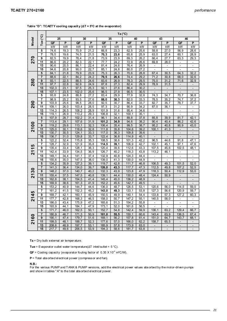
Table “D”: TCAET Y cooling cap acit y (∆T = 5°C at the evaporator)
Ta (°C) 25 30 35 40 43 46
QF P QF P QF P QF P QF P QF P Mod
el
Tue
(°C
)
kW kW kW kW kW kW kW kW kW kW kW kW 5 74,6 19,3 70,9 21,2 66,8 23,3 62,5 25,6 59,8 27,0 56,9 28,6 7 78,5 19,6 74,5 21,5 70,3 23,6 65,8 25,9 63,0 27,4 60,1 28,9 9 82,5 19,9 78,4 21,8 73,9 23,9 69,3 26,2 66,4 27,7 63,3 29,3 11 86,6 20,2 82,3 22,1 77,7 24,2 72,9 26,6 69,8 28,0 - - 13 90,6 20,5 86,1 22,4 81,4 24,6 76,4 26,9 - - - -
270
15 94,6 20,8 90,0 22,7 85,1 24,8 80,0 27,2 - - - - 5 84,1 21,8 79,9 23,9 75,3 26,3 70,6 28,8 67,4 30,5 64,3 32,2 7 88,6 22,1 84,2 24,2 79,5 26,6 74,4 29,2 71,2 30,8 68,0 32,6 9 93,1 22,5 88,5 24,6 83,6 26,9 78,3 29,5 75,0 31,2 71,6 32,9 11 97,7 22,8 92,9 24,9 87,8 27,3 82,4 29,9 78,9 31,5 - - 13 102,3 23,1 97,5 25,3 92,1 27,6 86,4 30,2 - - - -
280
15 107,1 23,5 102,0 25,6 96,5 27,9 90,5 30,5 - - - - 5 93,8 24,8 88,8 27,2 83,4 29,9 77,9 32,8 74,3 34,7 70,7 36,8 7 98,9 25,2 93,5 27,6 88,0 30,3 82,0 33,3 78,5 35,2 74,7 37,2 9 103,9 25,6 98,5 28,0 92,5 30,7 86,4 33,7 82,7 35,7 78,7 37,7 11 109,1 26,0 103,4 28,5 97,3 31,2 90,9 34,2 87,0 36,1 - - 13 114,3 26,5 108,2 28,9 101,9 31,6 95,4 34,6 - - - -
290
15 119,1 26,9 113,2 29,3 106,8 32,1 100,1 35,1 - - - - 5 107,9 28,7 102,2 31,4 96,1 34,4 89,8 37,8 85,8 39,9 81,7 42,1 7 113,4 29,1 107,6 31,9 101,2 34,9 94,6 38,2 90,4 40,4 86,2 42,6 9 119,2 29,6 113,1 32,3 106,4 35,4 99,5 38,7 95,2 40,8 90,9 43,0 11 125,0 30,1 118,6 32,8 111,8 35,8 104,6 39,2 100,1 41,3 - - 13 130,7 30,5 124,1 33,3 117,0 36,3 109,8 39,6 - - - - 21
00
15 136,7 31,0 129,8 33,7 122,4 36,8 114,9 40,1 - - - - 5 122,2 32,4 115,8 35,3 108,5 38,6 101,3 42,2 96,5 44,6 91,8 47,1 7 128,7 32,9 121,9 35,8 114,5 39,1 106,9 42,7 102,1 45,1 97,1 47,6 9 135,4 33,4 128,1 36,3 120,4 39,6 112,6 43,3 107,5 45,6 102,5 48,1 11 142,4 33,9 134,5 36,9 126,7 40,2 118,3 43,8 113,2 46,1 - - 13 149,1 34,4 141,1 37,4 132,9 40,8 124,3 44,4 - - - - 21
15
15 155,6 35,0 147,5 38,0 139,0 41,3 130,0 44,9 - - - - 5 134,2 35,9 127,3 39,1 119,7 42,8 111,7 46,8 106,5 49,3 101,5 52,0 7 141,3 36,4 134,0 39,7 126,0 43,3 117,7 47,3 112,5 49,8 107,2 52,5 9 148,2 37,0 140,7 40,2 132,3 43,9 123,8 47,9 118,3 50,4 112,9 53,0 11 155,4 37,5 147,5 40,8 139,1 44,4 130,0 48,4 124,4 50,9 - - 13 162,8 38,1 154,5 41,4 145,4 45,0 136,2 48,9 - - - - 21
30
15 169,9 38,6 161,3 41,9 152,2 45,6 142,7 49,5 - - - - 5 153,2 40,9 144,7 44,6 136,0 48,7 126,5 53,1 120,6 56,0 114,5 59,0 7 161,2 41,5 152,3 45,2 143,0 49,3 133,1 53,8 127,3 56,6 120,9 59,7 9 169,7 42,1 160,1 45,9 150,5 49,9 140,1 54,4 133,8 57,3 127,2 60,3 11 177,7 42,8 168,3 46,5 158,0 50,7 147,2 55,1 140,5 58,0 - - 13 186,0 43,4 175,9 47,2 165,6 51,3 154,2 55,8 - - - - 21
45
15 193,9 44,1 184,1 47,9 173,1 52,0 161,6 56,5 - - - - 5 171,7 46,0 162,5 50,1 152,7 54,8 142,4 59,9 136,1 63,2 129,4 66,7 7 180,9 46,7 171,3 50,9 161,0 55,5 150,1 60,6 143,4 63,9 136,5 67,4 9 190,1 47,4 179,7 51,6 169,1 56,2 157,8 61,4 151,0 64,7 143,7 68,1 11 199,5 48,1 188,7 52,3 177,6 57,0 166,0 62,2 158,7 65,5 - - 13 208,6 48,9 197,7 53,1 185,9 57,8 173,9 63,0 - - - - 21
60
15 217,7 49,6 206,5 53,9 194,3 58,6 181,7 63,8 - - - -
Ta = Dry bulb external air temper ature.
Tue = Evaporator outlet water temperature(∆T inlet/outlet = 5 °C).
QF = Cooling capacity (evaporator fouling factor of 0.35 X 10⁻⁴ m²C/W).
P = Total absorbed el ectrical power (compressor and fan).
N.B.: For the various PUMP and T ANK & PUMP versions, add the electrical power val ues absorbed by the motor-driven pumps and show i n tables " A" to the total absorbed el ectrical power.

TCAESY 270÷2160 performance
22
Table “D”: TCAESY cooling capacit y (∆T = 5°C at the evaporator)
Ta (°C) 25 30 35 40 43 46
QF P QF P QF P QF P QF P QF P Mod
el
Tue
(°C
)
kW kW kW kW kW kW kW kW kW kW kW kW 5 74,6 19,3 70,9 21,2 66,8 23,3 62,5 25,6 59,8 27,0 56,9 28,6 7 78,5 19,6 74,5 21,5 70,3 23,6 65,8 25,9 63,0 27,4 60,1 28,9 9 82,5 19,9 78,4 21,8 73,9 23,9 69,3 26,2 66,4 27,7 63,3 29,3 11 86,6 20,2 82,3 22,1 77,7 24,2 72,9 26,6 69,8 28,0 - - 13 90,6 20,5 86,1 22,4 81,4 24,6 76,4 26,9 - - - -
270
15 94,6 20,8 90,0 22,7 85,1 24,8 80,0 27,2 - - - - 5 84,1 21,8 79,9 23,9 75,3 26,3 70,6 28,8 67,4 30,5 64,3 32,2 7 88,6 22,1 84,2 24,2 79,5 26,6 74,4 29,2 71,2 30,8 68,0 32,6 9 93,1 22,5 88,5 24,6 83,6 26,9 78,3 29,5 75,0 31,2 71,6 32,9 11 97,7 22,8 92,9 24,9 87,8 27,3 82,4 29,9 78,9 31,5 - - 13 102,3 23,1 97,5 25,3 92,1 27,6 86,4 30,2 - - - -
280
15 107,1 23,5 102,0 25,6 96,5 27,9 90,5 30,5 - - - - 5 93,8 24,8 88,8 27,2 83,4 29,9 77,9 32,8 74,3 34,7 70,7 36,8 7 98,9 25,2 93,5 27,6 88,0 30,3 82,0 33,3 78,5 35,2 74,7 37,2 9 103,9 25,6 98,5 28,0 92,5 30,7 86,4 33,7 82,7 35,7 78,7 37,7 11 109,1 26,0 103,4 28,5 97,3 31,2 90,9 34,2 87,0 36,1 - - 13 114,3 26,5 108,2 28,9 101,9 31,6 95,4 34,6 - - - -
290
15 119,1 26,9 113,2 29,3 106,8 32,1 100,1 35,1 - - - - 5 107,9 28,7 102,2 31,4 96,1 34,4 89,8 37,8 85,8 39,9 81,7 42,1 7 113,4 29,1 107,6 31,9 101,2 34,9 94,6 38,2 90,4 40,4 86,2 42,6 9 119,2 29,6 113,1 32,3 106,4 35,4 99,5 38,7 95,2 40,8 90,9 43,0 11 125,0 30,1 118,6 32,8 111,8 35,8 104,6 39,2 100,1 41,3 - - 13 130,7 30,5 124,1 33,3 117,0 36,3 109,8 39,6 - - - - 21
00
15 136,7 31,0 129,8 33,7 122,4 36,8 114,9 40,1 - - - - 5 115,9 33,3 109,4 36,4 102,5 39,8 95,4 43,6 91,0 46,0 86,4 48,6 7 122,0 33,9 115,1 36,9 108,0 40,4 100,7 44,2 96,1 46,6 91,2 49,1 9 128,0 34,5 121,0 37,6 113,5 41,0 105,8 44,8 101,1 47,2 96,2 49,7 11 134,1 35,1 126,8 38,2 119,2 41,6 111,2 45,4 106,3 47,7 - - 13 140,4 35,7 132,9 38,8 124,9 42,3 116,7 46,0 - - - - 21
15
15 146,8 36,3 138,7 39,5 130,5 42,9 121,9 46,7 - - - - 5 127,6 36,8 120,5 40,2 113,2 44,0 105,3 48,1 100,4 50,7 95,4 53,5 7 133,9 37,4 126,7 40,8 119,0 44,6 110,8 48,7 105,9 51,3 100,8 54,0 9 140,6 38,1 133,1 41,5 125,0 45,2 116,6 49,3 111,3 51,9 105,9 54,6 11 147,5 38,7 139,5 42,1 131,1 45,9 122,3 50,0 116,8 52,5 - - 13 154,2 39,3 145,9 42,8 137,1 46,5 128,2 50,6 - - - - 21
30
15 160,7 40,0 152,3 43,5 143,5 47,2 134,1 51,3 - - - - 5 146,3 42,7 138,0 46,7 129,2 51,0 119,8 55,7 114,3 58,8 108,2 61,9 7 153,5 43,4 144,9 47,4 136,0 51,7 126,2 56,5 120,3 59,5 114,3 62,6 9 161,3 44,2 152,2 48,1 142,6 52,5 132,8 57,2 126,5 60,2 120,3 63,3 11 168,8 44,9 159,4 48,9 149,4 53,2 139,2 58,0 132,7 61,0 - - 13 176,5 45,7 166,7 49,7 156,7 54,1 145,9 58,8 - - - - 21
45
15 184,3 46,5 174,1 50,5 163,5 54,9 152,3 59,6 - - - - 5 162,2 48,0 153,0 52,3 143,5 57,3 133,4 62,6 127,1 66,1 120,9 69,7 7 170,2 48,8 160,9 53,2 151,0 58,1 140,5 63,5 134,1 66,9 127,3 70,5 9 178,6 49,5 168,9 54,0 158,4 59,0 147,6 64,4 140,8 67,7 134,0 71,3 11 187,1 50,4 177,0 54,9 166,0 59,9 154,8 65,3 147,8 68,6 - - 13 195,7 51,3 184,9 55,9 173,9 60,8 162,0 66,2 - - - - 21
60
15 204,1 52,3 193,0 56,8 181,6 61,8 169,4 67,2 - - - -
Ta = Dry bulb external air temper ature.
Tue = Evaporator outlet water temperature(∆T inlet/outlet = 5 °C).
QF = Cooling capacity (evaporator fouling factor of 0,35 X 10⁻⁴ m²C/W).
P = Total absorbed el ectrical power (compressor and fan).
N.B.: For the various PUMP and T ANK & PUMP versions, add the electrical power val ues absorbed by the motor-driven pumps and show i n tables " A" to the total absorbed el ectrical power.

TCAEQY 270÷2160 performance
23
Table “D”: TCAEQY cooling capacit y (∆T = 5°C at the evaporator)
Ta (°C) 25 30 35 40 43 46
QF P QF P QF P QF P QF P QF P Mod
el
Tue
(°C
) kW kW kW kW kW kW kW kW kW kW kW kW
5 71,3 20,2 67,6 22,2 63,6 24,4 59,4 26,8 56,8 28,4 54,0 30,0 7 74,9 20,6 71,1 22,6 67,0 24,8 62,4 27,2 59,8 28,8 57,0 30,4 9 78,7 20,9 74,7 22,9 70,4 25,1 65,8 27,6 62,9 29,1 59,9 30,8 11 82,5 21,3 78,4 23,3 73,8 25,5 69,1 27,9 66,0 29,5 - - 13 86,3 21,6 82,1 23,6 77,4 25,9 72,4 28,3 - - - -
270
15 90,1 22,0 85,7 24,0 80,9 26,2 75,8 28,7 - - - - 5 79,7 21,5 75,5 23,6 71,1 25,9 66,5 28,5 63,5 30,1 60,5 31,8 7 83,8 21,8 79,5 23,9 75,0 26,3 70,1 28,9 67,0 30,5 63,8 32,2 9 88,1 22,2 83,7 24,3 78,8 26,7 73,7 29,2 70,5 30,9 67,3 32,6 11 92,3 22,6 87,8 24,7 82,7 27,0 77,5 29,6 74,1 31,3 - - 13 96,6 22,9 91,8 25,0 86,8 27,4 81,2 30,0 - - - -
280
15 101,1 23,3 96,2 25,4 90,7 27,7 85,2 30,3 - - - - 5 88,4 25,7 83,6 28,2 78,4 31,0 73,0 34,1 69,6 36,1 66,2 38,1 7 93,0 26,2 87,9 28,7 82,5 31,5 76,9 34,6 73,4 36,6 69,9 38,6 9 97,7 26,6 92,4 29,2 86,8 32,0 81,0 35,1 77,3 37,0 73,7 39,1 11 102,4 27,1 96,9 29,7 91,1 32,5 85,0 35,6 81,3 37,6 - - 13 107,2 27,6 101,4 30,2 95,4 33,0 89,2 36,1 - - - -
290
15 111,8 28,1 105,8 30,7 99,7 33,5 93,3 36,6 - - - - 5 101,5 28,5 96,1 31,3 90,3 34,3 84,1 37,6 80,3 39,7 76,4 41,9 7 106,9 29,0 101,1 31,7 95,0 34,8 88,6 38,1 84,6 40,2 80,6 42,4 9 112,1 29,5 106,3 32,2 99,8 35,3 93,2 38,6 89,1 40,7 85,0 42,9 11 117,4 30,0 111,3 32,8 104,8 35,8 97,9 39,1 93,6 41,2 - - 13 122,9 30,5 116,5 33,3 109,7 36,3 102,7 39,6 - - - - 21
00
15 128,3 31,0 121,8 33,8 114,7 36,8 107,5 40,1 - - - - 5 109,3 35,6 102,8 38,9 96,0 42,5 89,0 46,4 84,7 48,9 80,3 51,5 7 114,7 36,3 108,0 39,6 101,0 43,2 93,8 47,1 89,3 49,6 84,8 52,1 9 120,2 37,0 113,4 40,3 106,0 43,9 98,5 47,8 93,9 50,2 89,3 52,8 11 125,9 37,7 118,7 41,1 111,0 44,7 103,3 48,5 98,7 50,9 - - 13 131,4 38,5 123,9 41,8 116,2 45,4 108,1 49,3 - - - - 21
15
15 137,1 39,2 129,3 42,6 121,2 46,2 113,0 50,0 - - - - 5 116,6 38,9 109,8 42,4 102,8 46,3 94,8 50,8 89,6 53,7 84,2 56,8 7 122,3 39,6 115,3 43,1 108,0 47,0 99,4 51,6 94,0 54,5 88,5 57,6 9 128,0 40,4 120,8 43,9 112,9 47,8 104,0 52,4 98,5 55,3 92,7 58,4 11 133,9 41,1 126,4 44,7 117,9 48,7 108,8 53,3 103,0 56,2 - - 13 139,8 41,9 131,9 45,5 122,9 49,6 113,5 54,1 - - - - 21
30
15 145,5 42,7 137,3 46,3 128,0 50,5 118,1 55,0 - - - - 5 135,8 44,5 127,5 48,6 119,0 53,0 110,3 57,8 104,7 60,8 99,1 64,0 7 142,3 45,3 134,0 49,4 125,0 53,9 115,7 58,7 110,1 61,7 104,4 64,7 9 149,1 46,2 140,4 50,3 131,1 54,8 121,4 59,5 115,5 62,5 109,8 65,5 11 155,7 47,1 146,6 51,2 137,0 55,7 127,2 60,4 121,2 63,4 - - 13 162,7 48,0 153,3 52,1 143,1 56,6 133,0 61,3 - - - - 21
45
15 169,3 48,9 159,5 53,1 149,3 57,6 138,9 62,2 - - - - 5 149,7 51,7 140,7 56,5 131,4 61,7 121,9 67,3 115,9 70,8 109,9 74,4 7 156,9 52,7 147,7 57,5 138,0 62,7 128,0 68,2 121,8 71,7 115,7 75,3 9 164,3 53,8 154,7 58,6 144,6 63,7 134,3 69,3 128,0 72,8 121,4 76,3 11 171,9 54,8 161,8 59,6 151,3 64,8 140,5 70,4 134,0 73,8 - - 13 179,2 55,9 168,8 60,8 158,2 66,0 146,8 71,5 - - - - 21
60
15 186,6 57,1 175,9 61,9 164,7 67,2 153,3 72,7 - - - -
Ta = Dry bulb external air temper ature.
Tue = Evaporator outlet water temperature(∆T inlet/outlet = 5 °C).
QF = Cooling capacity (evaporator fouling factor of 0.35 X 10⁻⁴ m²C/W).
P = Total absorbed el ectrical power (compressor and fan).
N.B.: For the various PUMP and T ANK & PUMP versions, add the electrical power val ues absorbed by the motor-driven pumps and show i n tables " A" to the total absorbed el ectrical power.

THAETY 270÷2160 performance
24
Table “D”: THAET Y cooling cap acit y (∆T = 5°C at the evaporator)
Ta (°C) 25 30 35 40 43 46
QF P QF P QF P QF P QF P QF P Mod
el
Tue
(°C
) kW kW kW kW kW kW kW kW kW kW kW kW
5 73,6 19,5 69,9 21,4 65,8 23,5 61,5 25,8 58,8 27,2 55,9 28,8 7 77,6 19,8 73,7 21,7 69,4 23,8 64,9 26,1 62,0 27,6 59,1 29,1 9 81,6 20,1 77,4 22,0 73,0 24,1 68,3 26,5 65,4 27,9 62,3 29,5 11 85,6 20,5 81,3 22,3 76,7 24,5 71,9 26,8 68,8 28,3 - - 13 89,7 20,8 85,3 22,7 80,5 24,8 75,5 27,1 - - - -
270
15 93,8 21,1 89,3 23,0 84,2 25,1 79,1 27,4 - - - - 5 82,3 21,7 78,2 23,8 73,6 26,1 68,7 28,7 65,7 30,3 62,6 32,0 7 86,8 22,1 82,3 24,2 77,7 26,5 72,6 29,0 69,4 30,7 66,2 32,4 9 91,4 22,5 86,6 24,5 81,8 26,8 76,5 29,4 73,3 31,0 69,8 32,8 11 95,9 22,8 91,2 24,9 86,0 27,2 80,5 29,8 77,2 31,4 - - 13 100,6 23,2 95,6 25,2 90,2 27,5 84,6 30,1 - - - -
280
15 105,4 23,5 100,0 25,5 94,6 27,8 88,8 30,4 - - - - 5 91,0 24,6 86,1 26,9 80,7 29,5 75,2 32,4 71,8 34,3 68,2 36,3 7 95,9 25,0 90,7 27,4 85,2 30,0 79,4 32,9 75,8 34,8 72,2 36,7 9 100,9 25,4 95,4 27,8 89,7 30,4 83,7 33,4 80,0 35,2 76,2 37,2 11 105,8 25,9 100,2 28,3 94,3 30,9 88,1 33,8 84,2 35,7 - - 13 110,9 26,3 105,1 28,7 98,9 31,4 92,5 34,3 - - - -
290
15 116,2 26,8 110,1 29,2 103,5 31,8 97,1 34,8 - - - - 5 105,9 28,8 100,2 31,5 94,2 34,4 87,8 37,7 83,9 39,8 79,8 42,0 7 111,5 29,2 105,5 31,9 99,3 34,9 92,8 38,2 88,5 40,3 84,3 42,5 9 117,3 29,7 111,0 32,4 104,4 35,4 97,6 38,7 93,3 40,8 88,7 42,9 11 123,0 30,2 116,6 32,9 109,8 35,9 102,5 39,1 98,1 41,2 - - 13 129,0 30,7 122,4 33,4 115,1 36,4 107,7 39,6 - - - - 21
00
15 134,9 31,2 127,9 33,9 120,4 36,9 112,8 40,1 - - - - 5 118,8 32,1 112,2 35,0 105,4 38,2 98,0 41,8 93,5 44,1 88,9 46,5 7 125,2 32,6 118,4 35,5 111,0 38,7 103,6 42,3 98,8 44,6 94,1 47,0 9 131,7 33,2 124,5 36,0 116,9 39,2 109,0 42,8 104,1 45,1 99,4 47,5 11 138,3 33,7 130,8 36,6 123,1 39,8 114,7 43,4 109,8 45,6 - - 13 144,9 34,2 137,3 37,1 129,1 40,4 120,6 43,9 - - - - 21
15
15 151,6 34,8 143,6 37,7 135,1 41,0 126,3 44,5 - - - - 5 132,2 36,0 125,2 39,3 117,6 42,8 109,6 46,8 104,6 49,3 99,4 52,0 7 139,4 36,6 131,9 39,8 123,8 43,4 115,7 47,3 110,4 49,9 105,0 52,5 9 146,4 37,2 138,7 40,4 130,4 44,0 121,7 47,9 116,2 50,4 110,7 53,0 11 153,9 37,7 145,6 41,0 137,0 44,6 128,0 48,5 122,3 51,0 - - 13 161,2 38,4 152,7 41,6 143,7 45,2 134,2 49,1 - - - - 21
30
15 168,7 39,0 159,7 42,2 150,3 45,8 140,3 49,7 - - - - 5 151,7 41,3 143,1 45,0 134,0 49,0 124,5 53,5 118,6 56,3 112,7 59,3 7 159,8 42,0 150,9 45,6 141,3 49,7 131,3 54,1 125,2 57,0 118,9 60,0 9 168,0 42,6 158,6 46,3 148,7 50,4 138,5 54,8 131,9 57,7 125,4 60,6 11 176,0 43,3 166,4 47,0 156,2 51,1 145,6 55,6 138,7 58,4 - - 13 184,5 44,0 174,5 47,8 163,8 51,9 152,4 56,3 - - - - 21
45
15 192,7 44,8 182,3 48,5 171,2 52,6 159,8 57,1 - - - - 5 171,1 46,7 161,5 50,8 151,5 55,5 141,1 60,6 134,5 63,9 128,0 67,3 7 180,3 47,4 170,4 51,5 159,8 56,2 148,8 61,3 142,1 64,7 135,0 68,1 9 189,6 48,1 178,9 52,3 168,3 57,0 156,8 62,1 149,6 65,5 142,3 68,9 11 198,8 48,9 188,0 53,1 176,5 57,8 164,6 63,0 157,2 66,3 - - 13 208,5 49,8 197,3 54,0 185,3 58,7 173,0 63,9 - - - - 21
60
15 217,9 50,6 206,2 54,9 193,8 59,6 181,1 64,8 - - - -
Ta = Dry bulb external air temper ature.
Tue = Evaporator outlet water temperature(∆T inlet/outlet = 5 °C).
QF = Cooling capacity (evaporator fouling factor of 0,35 X 10⁻⁴ m²C/W).
P = Total absorbed el ectrical power (compressor and fan).
N.B.: For the various PUMP and T ANK & PUMP versions, add the electrical power val ues absorbed by the motor-driven pumps and show i n tables " A" to the total absorbed el ectrical power.

THAETY 270÷2160 performance
25
Tab le “D”: THAETY heating capacit y (∆T = 5°C at the conden ser)
Tuc (°C) 30 35 40 45 50 53
QT P QT P QT P QT P QT P QT P Mod
el
Ta (°
C)
RH
(%)
kW kW kW kW kW kW kW kW kW kW kW kW -5 90 61,6 16,4 61,0 18,3 60,4 20,4 - - - - - - 0 90 70,1 16,7 69,3 18,5 68,3 20,7 67,3 23,0 - - - - 7 90 83,2 17,0 81,9 18,9 80,5 21,1 79,0 23,5 77,5 26,2 76,5 28,0 10 85 88,8 17,2 87,3 19,1 85,6 21,2 84,0 23,7 82,2 26,4 81,0 28,2 15 85 100,1 17,6 98,3 19,4 96,2 21,5 94,2 24,0 91,9 26,7 90,5 28,6
270
20 85 112,8 18,1 110,5 19,8 108,0 21,8 105,2 24,2 102,3 27,0 - - -5 90 67,0 17,6 66,3 19,5 65,7 21,7 - - - - - - 0 90 76,4 17,8 75,4 19,8 74,3 22,0 73,2 24,5 - - - - 7 90 90,6 18,2 89,1 20,2 87,6 22,4 86,0 25,0 84,3 27,8 83,3 29,7 10 85 96,8 18,4 95,3 20,4 93,4 22,6 91,5 25,2 89,5 28,0 88,1 29,9 15 85 109,5 18,9 107,4 20,7 105,0 22,9 102,6 25,5 100,0 28,3 98,3 30,3
280
20 85 123,2 19,4 120,6 21,1 117,8 23,2 114,7 25,7 111,5 28,6 - - -5 90 75,0 20,5 74,1 22,6 73,3 25,2 - - - - - - 0 90 85,6 20,8 84,1 23,0 83,0 25,6 81,8 28,6 - - - - 7 90 101,6 21,3 99,8 23,5 97,8 26,2 96,0 29,2 94,4 32,7 93,3 34,9 10 85 108,5 21,5 106,3 23,7 104,3 26,3 102,3 29,4 100,1 32,9 98,9 35,2 15 85 122,6 22,0 119,8 24,1 117,3 26,8 114,7 29,8 111,9 33,3 110,3 35,6
290
20 85 138,9 22,5 135,2 24,6 131,7 27,2 128,5 30,2 125,0 33,7 - - -5 90 86,9 23,5 86,0 26,0 84,9 28,9 - - - - - - 0 90 99,1 23,8 97,5 26,4 96,0 29,3 94,4 32,6 - - - - 7 90 118,1 24,4 115,8 26,9 113,5 29,8 111,0 33,2 108,6 37,0 107,1 39,4 10 85 126,3 24,7 123,5 27,2 120,9 30,1 118,2 33,4 115,1 37,2 113,4 39,7 15 85 142,8 25,2 139,6 27,7 136,3 30,6 132,6 33,9 129,0 37,7 126,6 40,1 21
00
20 85 161,3 25,8 157,2 28,2 153,1 31,1 148,7 34,4 144,0 38,1 - - -5 90 95,7 27,3 94,3 29,9 93,1 33,1 - - - - - - 0 90 109,2 27,7 107,2 30,3 105,3 33,6 103,6 37,4 - - - - 7 90 130,3 28,3 127,3 31,0 124,6 34,2 122,0 38,0 119,3 42,3 117,7 45,1 10 85 139,3 28,6 136,2 31,3 133,1 34,5 129,9 38,3 126,6 42,5 124,8 45,4 15 85 157,8 29,1 153,9 31,8 150,0 35,1 145,9 38,8 142,1 43,1 139,5 45,9 21
15
20 85 178,3 29,7 173,6 32,4 168,8 35,7 164,0 39,4 159,0 43,7 - - -5 90 109,1 30,2 107,7 33,2 106,4 36,8 - - - - - - 0 90 124,5 30,6 122,4 33,7 120,3 37,2 118,0 41,4 - - - - 7 90 148,7 31,4 145,3 34,4 142,3 37,9 139,0 42,0 135,6 46,6 133,5 49,7 10 85 158,9 31,7 155,4 34,7 151,8 38,2 148,0 42,3 143,8 46,9 141,6 49,9 15 85 180,2 32,3 175,7 35,3 171,2 38,8 166,4 42,9 161,2 47,5 158,2 50,5 21
30
20 85 203,9 32,9 198,3 36,0 192,7 39,5 186,7 43,6 180,4 48,2 - - -5 90 123,2 35,3 121,9 38,9 120,7 43,0 - - - - - - 0 90 140,3 35,8 138,3 39,3 136,0 43,4 134,2 48,2 - - - - 7 90 166,1 36,5 163,2 40,0 160,0 44,1 157,0 48,8 153,6 54,1 151,6 57,6 10 85 177,5 36,8 174,0 40,3 170,4 44,4 166,9 49,1 163,1 54,4 160,9 57,9 15 85 200,1 37,4 196,0 40,9 191,5 45,0 186,8 49,8 181,7 55,1 178,8 58,6 21
45
20 85 227,1 38,2 220,3 41,7 214,4 45,8 208,5 50,5 202,2 55,9 - - -5 90 136,6 39,3 135,0 43,4 133,5 48,1 - - - - - - 0 90 156,5 39,8 153,6 43,8 151,1 48,5 148,8 53,8 - - - - 7 90 186,9 40,7 182,8 44,6 179,0 49,2 175,0 54,5 171,0 60,6 168,8 64,5 10 85 200,0 41,0 195,4 44,9 190,7 49,6 186,3 54,9 181,7 60,9 178,8 64,9 15 85 227,1 41,8 221,3 45,7 215,4 50,3 209,7 55,7 203,7 61,8 199,8 65,7 21
60
20 85 256,8 42,7 250,1 46,6 242,9 51,3 235,7 56,7 228,0 62,8 - -
Tuc = Condenser outlet water temperature (∆T inlet /outlet = 5 °C).
Ta = Dry bulb external air temper ature.
RH = Relative humi dity.
QT = Heating capacity (evaporator fouling factor of 0,35 X 10⁻⁴ m²C/W).
P = Total absorbed el ectrical power (compressor and fan).
N.B.: For the various PUMP and T ANK & PUMP versions, add the electrical power val ues absorbed by the motor-driven pumps and show i n tables " A" to the total absorbed el ectrical power.

THAESY 270÷2160 performance
26
Table “D”: THAESY cooling capacit y (∆T = 5°C at the evaporator)
Ta (°C) 25 30 35 40 43 46
QF P QF P QF P QF P QF P QF P Mod
el
Tue
(°C
) kW kW kW kW kW kW kW kW kW kW kW kW
5 73,6 19,5 69,9 21,4 65,8 23,5 61,5 25,8 58,8 27,2 55,9 28,8 7 77,6 19,8 73,7 21,7 69,4 23,8 64,9 26,1 62,0 27,6 59,1 29,1 9 81,6 20,1 77,4 22,0 73,0 24,1 68,3 26,5 65,4 27,9 62,3 29,5 11 85,6 20,5 81,3 22,3 76,7 24,5 71,9 26,8 68,8 28,3 - - 13 89,7 20,8 85,3 22,7 80,5 24,8 75,5 27,1 - - - -
270
15 93,8 21,1 89,3 23,0 84,2 25,1 79,1 27,4 - - - - 5 82,3 21,7 78,2 23,8 73,6 26,1 68,7 28,7 65,7 30,3 62,6 32,0 7 86,8 22,1 82,3 24,2 77,7 26,5 72,6 29,0 69,4 30,7 66,2 32,4 9 91,4 22,5 86,6 24,5 81,8 26,8 76,5 29,4 73,3 31,0 69,8 32,8 11 95,9 22,8 91,2 24,9 86,0 27,2 80,5 29,8 77,2 31,4 - - 13 100,6 23,2 95,6 25,2 90,2 27,5 84,6 30,1 - - - -
280
15 105,4 23,5 100,0 25,5 94,6 27,8 88,8 30,4 - - - - 5 91,0 24,6 86,1 26,9 80,7 29,5 75,2 32,4 71,8 34,3 68,2 36,3 7 95,9 25,0 90,7 27,4 85,2 30,0 79,4 32,9 75,8 34,8 72,2 36,7 9 100,9 25,4 95,4 27,8 89,7 30,4 83,7 33,4 80,0 35,2 76,2 37,2 11 105,8 25,9 100,2 28,3 94,3 30,9 88,1 33,8 84,2 35,7 - - 13 110,9 26,3 105,1 28,7 98,9 31,4 92,5 34,3 - - - -
290
15 116,2 26,8 110,1 29,2 103,5 31,8 97,1 34,8 - - - - 5 105,9 28,8 100,2 31,5 94,2 34,4 87,8 37,7 83,9 39,8 79,8 42,0 7 111,5 29,2 105,5 31,9 99,3 34,9 92,8 38,2 88,5 40,3 84,3 42,5 9 117,3 29,7 111,0 32,4 104,4 35,4 97,6 38,7 93,3 40,8 88,7 42,9 11 123,0 30,2 116,6 32,9 109,8 35,9 102,5 39,1 98,1 41,2 - - 13 129,0 30,7 122,4 33,4 115,1 36,4 107,7 39,6 - - - - 21
00
15 134,9 31,2 127,9 33,9 120,4 36,9 112,8 40,1 - - - - 5 115,2 33,9 108,8 36,9 101,7 40,4 94,6 44,2 90,2 46,6 85,6 49,1 7 121,3 34,5 114,4 37,5 107,2 41,0 99,7 44,8 95,1 47,2 90,4 49,7 9 127,6 35,1 120,2 38,2 113,0 41,6 105,1 45,4 100,3 47,8 95,4 50,3 11 133,7 35,7 126,3 38,9 118,6 42,3 110,5 46,1 105,4 48,4 - - 13 140,0 36,4 132,2 39,5 124,1 43,0 115,8 46,7 - - - - 21
15
15 146,2 37,0 138,3 40,2 129,9 43,7 121,2 47,4 - - - - 5 127,2 37,5 120,1 40,9 112,6 44,6 104,7 48,7 99,6 51,3 94,7 54,1 7 133,9 38,2 126,4 41,6 118,5 45,3 110,4 49,4 105,3 52,0 100,0 54,7 9 140,5 38,8 132,6 42,2 124,6 46,0 116,1 50,0 110,8 52,6 105,4 55,3 11 147,4 39,5 139,2 42,9 130,8 46,7 121,8 50,7 116,4 53,3 - - 13 154,0 40,2 145,6 43,7 136,9 47,4 127,6 51,4 - - - - 21
30
15 161,2 40,9 152,4 44,4 143,0 48,1 133,7 52,1 - - - - 5 146,2 43,5 137,7 47,5 128,9 51,8 119,3 56,5 113,7 59,5 107,6 62,7 7 153,8 44,3 144,8 48,2 135,6 52,6 126,0 57,3 119,9 60,3 113,7 63,4 9 161,5 45,1 152,2 49,1 142,5 53,4 132,4 58,1 126,0 61,1 119,7 64,2 11 169,3 45,9 159,7 49,9 149,6 54,3 138,9 59,0 132,4 61,9 - - 13 177,3 46,7 167,1 50,8 156,5 55,1 145,7 59,8 - - - - 21
45
15 184,8 47,6 174,6 51,6 163,6 56,0 152,4 60,7 - - - - 5 161,7 48,7 152,6 53,1 142,8 58,0 132,5 63,3 126,2 66,7 119,7 70,3 7 170,3 49,5 160,5 54,0 150,2 58,9 139,7 64,2 133,2 67,6 126,3 71,1 9 178,9 50,4 168,6 54,9 158,0 59,9 146,8 65,2 140,0 68,5 133,0 72,1 11 187,2 51,4 176,8 55,9 165,6 60,8 154,2 66,1 147,2 69,5 - - 13 196,0 52,3 185,2 56,9 173,6 61,8 161,6 67,2 - - - - 21
60
15 204,6 53,3 193,3 57,9 181,3 62,9 168,9 68,2 - - - -
Ta = Dry bulb external air temper ature.
Tue = Evaporator outlet water temperature(∆T inlet/outlet = 5 °C).
QF = Cooling capacity (evaporator fouling factor of 0.35 X 10⁻⁴ m²C/W).
P = Total absorbed el ectrical power (compressor and fan).
N.B.: For the various PUMP and T ANK & PUMP versions, add the electrical power val ues absorbed by the motor-driven pumps and show i n tables " A" to the total absorbed el ectrical power.

THAESY 270÷2160 performance
27
Tab le “D”: THAESY heating capacit y (∆T = 5°C at the condenser)
Tuc (°C) 30 35 40 45 50 53
QT P QT P QT P QT P QT P QT P Mod
el
Ta (°
C)
RH
(%)
kW kW kW kW kW kW kW kW kW kW kW kW -5 90 61,6 16,4 61,0 18,3 60,4 20,4 - - - - - - 0 90 70,1 16,7 69,3 18,5 68,3 20,7 67,3 23,0 - - - - 7 90 83,2 17,0 81,9 18,9 80,5 21,1 79,0 23,5 77,5 26,2 76,5 28,0 10 90 88,8 17,2 87,3 19,1 85,6 21,2 84,0 23,7 82,2 26,4 81,0 28,2 15 85 100,1 17,6 98,3 19,4 96,2 21,5 94,2 24,0 91,9 26,7 90,5 28,6
270
20 85 112,8 18,1 110,5 19,8 108,0 21,8 105,2 24,2 102,3 27,0 - - -5 85 67,0 17,6 66,3 19,5 65,7 21,7 - - - - - - 0 90 76,4 17,8 75,4 19,8 74,3 22,0 73,2 24,5 - - - - 7 90 90,6 18,2 89,1 20,2 87,6 22,4 86,0 25,0 84,3 27,8 83,3 29,7 10 90 96,8 18,4 95,3 20,4 93,4 22,6 91,5 25,2 89,5 28,0 88,1 29,9 15 85 109,5 18,9 107,4 20,7 105,0 22,9 102,6 25,5 100,0 28,3 98,3 30,3
280
20 85 123,2 19,4 120,6 21,1 117,8 23,2 114,7 25,7 111,5 28,6 - - -5 85 75,0 20,5 74,1 22,6 73,3 25,2 - - - - - - 0 90 85,6 20,8 84,1 23,0 83,0 25,6 81,8 28,6 - - - - 7 90 101,6 21,3 99,8 23,5 97,8 26,2 96,0 29,2 94,4 32,7 93,3 34,9 10 90 108,5 21,5 106,3 23,7 104,3 26,3 102,3 29,4 100,1 32,9 98,9 35,2 15 85 122,6 22,0 119,8 24,1 117,3 26,8 114,7 29,8 111,9 33,3 110,3 35,6
290
20 85 138,9 22,5 135,2 24,6 131,7 27,2 128,5 30,2 125,0 33,7 - - -5 85 86,9 23,5 86,0 26,0 84,9 28,9 - - - - - - 0 90 99,1 23,8 97,5 26,4 96,0 29,3 94,4 32,6 - - - - 7 90 118,1 24,4 115,8 26,9 113,5 29,8 111,0 33,2 108,6 37,0 107,1 39,4 10 90 126,3 24,7 123,5 27,2 120,9 30,1 118,2 33,4 115,1 37,2 113,4 39,7 15 85 142,8 25,2 139,6 27,7 136,3 30,6 132,6 33,9 129,0 37,7 126,6 40,1 21
00
20 85 161,3 25,8 157,2 28,2 153,1 31,1 148,7 34,4 144,0 38,1 - - -5 85 93,8 26,5 92,7 29,2 91,8 32,4 - - - - - - 0 90 106,9 26,9 105,3 29,6 103,7 32,8 102,4 36,7 - - - - 7 90 127,3 27,5 124,7 30,2 122,3 33,5 120,0 37,3 117,7 41,6 116,3 44,5 10 90 135,8 27,8 132,9 30,5 130,2 33,7 127,7 37,5 124,9 41,9 123,3 44,7 15 85 154,1 28,3 150,2 31,0 146,8 34,3 143,4 38,1 139,8 42,4 137,6 45,2 21
15
20 85 175,2 28,9 170,2 31,6 165,3 34,9 160,8 38,7 156,2 43,0 - - -5 85 105,7 29,1 104,7 32,0 103,6 35,6 - - - - - - 0 90 120,4 29,5 118,8 32,5 116,9 36,1 115,1 40,2 - - - - 7 90 143,4 30,2 140,5 33,2 137,9 36,7 135,0 40,8 132,0 45,4 130,1 48,4 10 90 153,3 30,5 150,1 33,4 146,9 37,0 143,6 41,1 140,1 45,7 138,0 48,7 15 85 173,5 31,0 169,4 34,0 165,4 37,6 161,3 41,7 156,7 46,2 153,9 49,2 21
30
20 85 196,4 31,7 191,4 34,7 186,2 38,3 180,9 42,3 175,3 46,9 - - -5 85 120,6 34,0 119,7 37,5 118,8 41,7 - - - - - - 0 90 137,0 34,4 135,2 37,9 133,5 42,0 132,1 46,8 - - - - 7 90 161,7 35,1 159,1 38,5 156,6 42,6 154,0 47,4 151,2 52,7 149,5 56,3 10 90 172,6 35,4 169,6 38,8 166,5 42,9 163,2 47,6 160,1 53,0 158,3 56,5 15 85 196,5 36,0 191,5 39,5 186,8 43,6 182,6 48,3 178,1 53,7 175,8 57,2 21
45
20 85 223,3 36,8 216,9 40,2 210,8 44,3 204,3 49,0 198,2 54,4 - - -5 85 132,2 37,9 131,0 42,0 129,9 46,7 - - - - - - 0 90 150,8 38,4 148,7 42,3 146,7 47,0 145,0 52,4 - - - - 7 90 179,7 39,1 176,2 43,1 173,0 47,7 170,0 53,0 166,7 59,1 164,7 63,0 10 90 192,3 39,5 188,2 43,4 184,3 48,0 180,7 53,4 176,9 59,4 174,5 63,4 15 85 218,1 40,2 212,8 44,1 208,2 48,7 202,8 54,1 197,8 60,2 194,4 64,2 21
60
20 85 248,2 41,1 241,5 45,0 234,2 49,7 227,9 55,0 221,4 61,1 - -
Tuc = Condenser outlet water temperature(∆T inlet/outlet = 5 °C).
Ta = Dry bulb external air temper ature.
RH = Relative humi dity.
QT = Heating capacity (evaporator fouling fac tor of 0.35 X 10⁻⁴ m²C/W).
P = Total absorbed el ectrical power (compressor and fan).
N.B.: For the various PUMP and T ANK & PUMP versions, add the electrical power val ues absorbed by the motor-driven pumps and show i n tables " A" to the total absorbed el ectrical power.
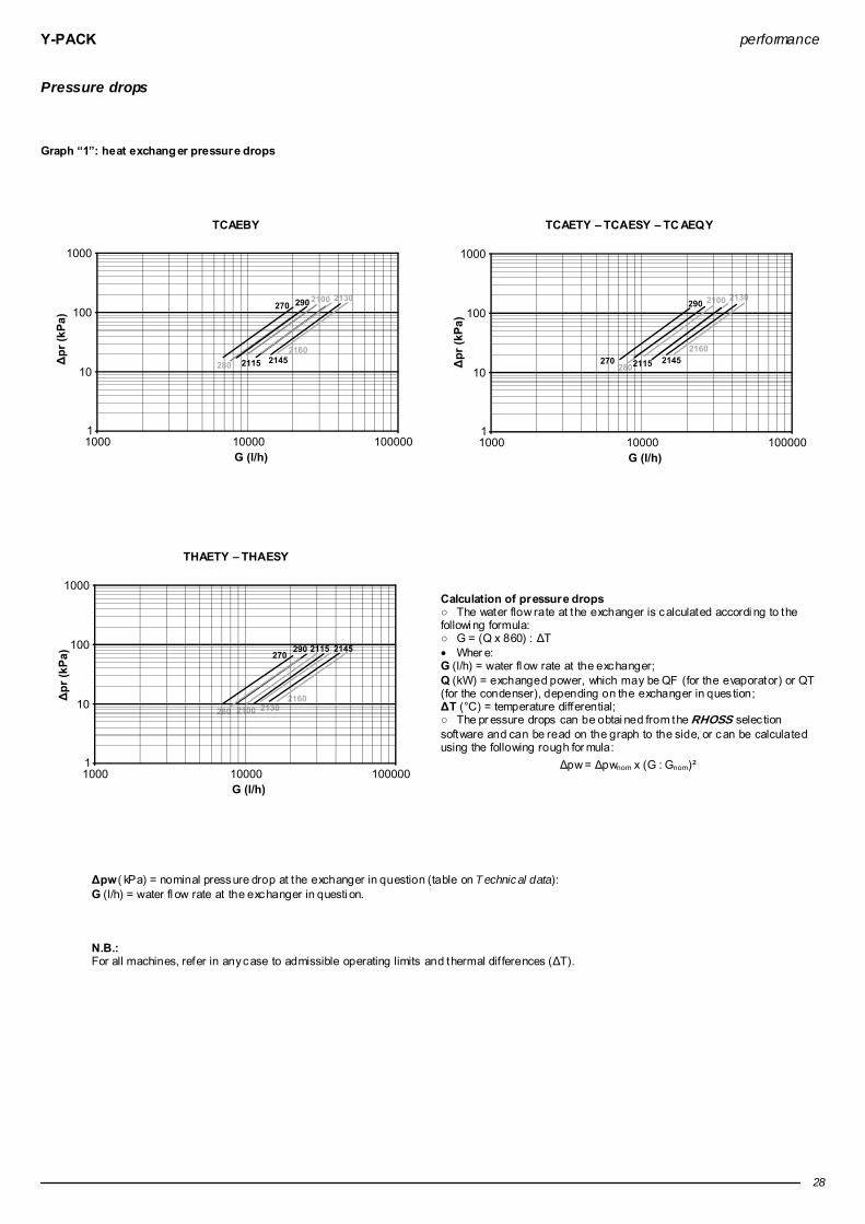
Y-PACK performance
28
Pressure drops Graph “1”: heat exchang er pressure drops
TCAEBY
TCAETY – TCAESY – TC AEQY
THAETY – THAESY
Calculation of pressure drops ○ The water flow rate at the exchanger is calculated accordi ng to the followi ng formula: ○ G = (Q x 860) : ∆T • Wher e: G (l/h) = water fl ow rate at the exchanger; Q (kW) = exchanged power, which may be QF (for the evaporator) or QT (for the condenser), depending on the exchanger in ques tion; ∆T (°C) = temperature differential; ○ The pr essure drops can be obtai ned from the RHOSS selec tion software and can be read on the graph to the side, or can be calculated using the following rough for mula:
∆pw = ∆pwnom x (G : Gnom)²
∆pw ( kPa) = nominal pressure drop at the exchanger in question (table on T echnical data): G (l/h) = water fl ow rate at the exchanger in questi on.
N.B.: For all machines, refer in any case to admissible operating limits and thermal dif ferences (∆T).

Y-PACK performance
29
Residual static pressure Graph “2”: residu al st atic pressure
TCAEBY 270÷2160 inst allation P1-DP1
TCAEBY 270÷2160 inst allation P2-DP2
TCAETY-TCAESY-TCAEQY 270÷2160 in stallation P1-DP1

Y-PACK performance
30
TCAETY-TCAESY-TCAEQY 270÷2160 in stallation P2-DP2
THAETY-THAESY 270÷2160 in stallation P1-DP1
THAETY-THAESY 270÷2160 in stallation P2-DP2

Y-PACK performance
31
TCAEBY 270÷2160 inst allation ASP1- ASDP1
TCAEBY 270÷2160 inst allation ASP2- ASDP2
TCAETY-TCAESY-TCAEQY 270÷2160 in stallation ASP1- ASDP1

Y-PACK performance
32
TCAETY-TCAESY-TCAEQY 270÷2160 in stallation ASP2- ASDP2
THAETY-THAESY 270÷2160 in stallation ASP1- ASDP1
THAETY-THAESY 270÷2160 in stallation ASP2- ASDP2
∆pr (kPa) = Resi dual static pressur e G (l/h) = Water flow Calculation of residu al st atic pressure The residual static pressure values can be obtained from graph “2” based on measured flow rates.

Y-PACK performance
33
Power levels and sound pressure
Sound power level in dB(A) b y octave b ands Pressure level in dB(A) Model 125 Hz 250 Hz 500 Hz 1000 Hz 2000 Hz 4000 Hz 8000 Hz Lw Lp 10m Lp 5m Lp 1m
270 89 82 79 76 73 65 59 82 53 60 68 280 89 82 79 76 73 65 59 82 53 60 68 290 89 82 79 76 73 65 59 82 53 60 68
2100 90 84 81 79 76 67 62 84 55 62 70 2115 86 84 86 87 82 74 64 90 61 68 76 2130 86 84 86 87 82 74 64 90 61 68 76 2145 86 84 86 87 82 74 64 90 61 68 76
TCA
EBY
2160 86 84 87 88 84 76 67 91 62 69 77 270 79 76 73 72 67 61 51 76 50 55 65 280 80 78 73 74 68 62 53 77 51 56 66 290 80 78 73 74 68 62 53 77 51 56 66
2100 81 79 74 75 69 63 55 78 52 57 68 2115 89 83 81 80 76 67 61 84 55 60 70 2130 89 83 81 80 76 67 61 84 55 60 70 2145 90 84 82 81 78 69 63 85 56 62 71
TCA
ETY
THA
ETY
2160 90 84 82 81 78 69 63 85 56 62 71 270 78 74 73 69 65 57 49 74 48 53 63 280 79 75 73 71 66 59 50 75 49 54 64 290 79 75 73 71 66 59 50 75 49 54 64
2100 79 76 73 72 67 61 51 76 50 55 65 2115 83 81 79 77 70 61 53 81 52 57 67 2130 83 81 79 77 70 61 53 81 52 57 67 2145 85 83 80 78 73 64 57 82 53 58 68
TCA
ESY
THA
ESY
2160 85 83 80 78 73 64 57 82 53 58 68 270 76 72 71 67 63 55 48 72 46 51 61 280 77 73 72 68 64 56 49 73 47 52 62 290 77 73 72 68 64 56 49 73 47 52 62
2100 78 74 73 69 65 57 49 74 48 53 63 2115 80 78 76 75 67 59 50 78 49 54 64 2130 80 78 76 75 67 59 50 78 49 54 64 2145 81 79 77 76 68 60 52 79 50 55 65
TCA
EQY
2160 81 79 77 76 68 60 52 79 50 55 65
Lw Sound power l evel in dB(A) on the basis of measur ements made in compliance with the UNI EN-ISO 3744 standard and Eurovent 8/1. The noise measurement refers to the units without pump.
Lp Sound pressure level i n dB(A) in reference to the measurement and distance from the unit indicated in the table, with directi onality factor of 2. The noise measur ement refers to the units without pump.
Note: With an exter nal air temperature of under 35°C in the pr esence of the FI10 accessor y (as standard i n versions T, S and Q), the machine noise levels fall to below the nominal value indicated in the table. It is not possible to extrapolate sound pressure values for distances of under 10 m.

Y-PACK operating limits
34
Operating limits Summer operation
105 15
40
46
50
0
-10
20
B
105 15
40
45
50
0
-10
20
T-S-Q
Operati on with condensation control
Operati on with stepped cooling capacity. T (°C) = Air temperature (B.S.). t (°C) = Water temperature In summer mode: Maxi mum inlet water temperature 20°C.
W inter operation
0 5-5 10 15 40
40
35
45
50
53
-10
T (°C) = Air temperature (B.S.). t (°C) = Water temperature In winter operation: Maxi mum inlet water temperature 47°C
Temperature differentials p ermitted through the exchangers ○ Heat differential at the evaporator ∆T = 3 ÷ 8°C ( with both compressors on) for machines with "standard" i nstallation. The maximum and minimum temperature differ ential for the “Pump” and “Tank&Pump” machines is linked to the pump perfor mances, which must al ways be checked with the help of the graphs on page 29 or using the RHOSS selec tion software. ○ Minimum water pressur e 0.5 Barg ○ Maxi mum water pressure 6 Barg. ○ Maxi mum water pressure on heat recover y and desuperheater 3 Barg. N.B.: For evaporator outlet water at a temperature of under 5°C, please contact the RHOSS S.p.A. pre-sales ser vice before or dering.
Model TCAEBY TCAETY-THAET Y-TCAESY-THAESY-TCAEQY TCAESY-TH AESY TCAEQY Tmax = 43°C (1)(2) Tmax = 46°C (1)(2) Tmax = 40°C (1)(3) Tmax = 37°C (1)(3) 270÷2160 Tmax = 46°C (1)(4) Tmax = 50°C (1)(4) - -
(1) Water temperature (IN/OUT) 12/7 °C. (2) Maxi mum external air temperature with unit in standard operation running on full and unsilenced. (3) Maxi mum external air temperature with unit in silenced mode. (4) Maxi mum external air temperature with unit with shuttered cooling capacity.
Use of anti-freeze solutions ○ The use of ethylene gl ycol is recommended if you do not wish to drai n the water from the hydraulic system during the wi nter stoppage, or if the unit has to suppl y chilled water at temperatures l ower than 5°C The additi on of glycol changes the physical properties of the water and consequentl y the perfor mance of the unit. T he proper percentage of glycol to be added to the system can be obtained from the most demandi ng operating conditi ons fr om those shown below.
○ Table "H" shows the multipli ers which allow the changes in perfor mance of the units to be determined in proportion to the required percentage of ethylene glycol. • The multipliers refer to the following conditi ons: condenser inl et water temperature 35°C; chilled water outlet temperature 7°C; temperature differ ential at evaporator and condenser 5°C. • For different operating conditi ons, the same coefficients can be used as their variations ar e negligible.
○ The el ectric heater for the water side heat exchanger (RA accessor y), the water buffer tank (RAS accessor y), the motor-driven pump assembl y (RAE accessory) and the desuperheater or heat recover y (RDR accessor y) prevents ice formation during winter breaks (as long as the unit is not disconnec ted from the power suppl y). Attention: Over 20% glycol, check the pump absorption limits (in versions P1-P2, DP1-DP2, ASP1-ASP2, ASDP1-ASD P2).
T able “H” % glycol in weight 10 % 15 % 20 % 25 % 30 % Freezing temp erature °C -5 -7 -10 -13 -16 fc QF 0,991 0,987 0,982 0,978 0,974 fc P 0,996 0,995 0,993 0,991 0,989 fc ∆pw 1,053 1,105 1,184 1,237 1,316 fc G 1,008 1,028 1,051 1,074 1,100
fc QF = Cooling capacity correction factor. fc P= Correction fac tor for the absorbed electrical current. fc ∆pw = Correction factor of the pr essure drops in the evaporator fc G = Correction fac tor of the glycol water flow to the evaporator

Y-PACK performance
35
RC100 and DS accessories: performances and pressure drops
Table”G”: Performance and pressure drops RC100 accessory for TC AEBY mod els
RC100 - 100% recovery 270 280 Water inlet/outlet temper ature °C 35/40 (**) 40/45 (*) 45/50 (**) 35/40 (**) 40/45 (*) 45/50 (**) Nominal heating capacity (•) kW 93,1 91,0 88,6 103,6 101,0 98,3 Recover y nominal fl ow m³/h 16,2 15,9 15,7 18,0 17,6 17,5 Recover y nominal pressure drops kPa 43,3 41,7 41,2 38,1 36,5 36,1 Recover y water content l 6,9 8,4 RC100 - 100% recovery 290 2100 Water inlet/outlet temper ature °C 35/40 (**) 40/45 (*) 45/50 (**) 35/40 (**) 40/45 (*) 45/50 (**) Nominal heating capacity (•) kW 116,0 113,0 110,2 132,5 129,0 125,3 Recover y nominal fl ow m³/h 20,2 19,7 19,6 23,0 22,5 22,3 Recover y nominal pressure drops kPa 46,7 44,7 44,3 45,7 43,7 43,0 Recover y water content l 8,4 9,9 RC100 - 100% recovery 2115 2130 Water inlet/outlet temper ature °C 35/40 (**) 40/45 (*) 45/50 (**) 35/40 (**) 40/45 (*) 45/50 (**) Nominal heating capacity (•) kW 150,2 146,0 141,8 165,7 161,0 156,2 Recover y nominal fl ow m³/h 26,1 25,4 25,2 28,8 28,0 27,8 Recover y nominal pressure drops kPa 47,5 45,3 44,6 47,1 44,9 44,1 Recover y water content l 11,1 12,6 RC100 - 100% recovery 2145 2160 Water inlet/outlet temper ature °C 35/40 (**) 40/45 (*) 45/50 (**) 35/40 (**) 40/45 (*) 45/50 (**) Nominal heating capacity (•) kW 190,4 185,0 179,8 212,9 207,0 201,3 Recover y nominal fl ow m³/h 33,1 32,2 31,9 37,0 36,1 35,8 Recover y nominal pressure drops kPa 47,9 45,7 44,9 48,3 46,0 45,4 Recover y water content l 14,9 17,4
Table”G”: Performance and pressure drops RC100 accessory for TC AETY-TCAESY-TCAEQY models
RC100 - 100% recovery 270 280 Water inlet/outlet temper ature °C 35/40 (**) 40/45 (*) 45/50 (**) 35/40 (**) 40/45 (*) 45/50 (**) Nominal heating capacity (•) kW 94,1 92,0 89,6 106,7 104,0 101,3 Recover y nominal fl ow m³/h 16,4 16,0 15,9 18,5 18,1 18,0 Recover y nominal pressure drops kPa 44,1 42,5 42,0 40,1 38,5 38,0 Recover y water content l 6,9 8,4 RC100 - 100% recovery 290 2100 Water inlet/outlet temper ature °C 35/40 (**) 40/45 (*) 45/50 (**) 35/40 (**) 40/45 (*) 45/50 (**) Nominal heating capacity (•) kW 119,1 116,0 113,1 137,6 134,0 130,1 Recover y nominal fl ow m³/h 20,7 20,2 20,1 23,9 23,3 23,1 Recover y nominal pressure drops kPa 48,9 46,8 46,4 48,9 46,8 46,0 Recover y water content l 8,4 9,9 RC100 - 100% recovery 2115 2130 Water inlet/outlet temper ature °C 35/40 (**) 40/45 (*) 45/50 (**) 35/40 (**) 40/45 (*) 45/50 (**) Nominal heating capacity (•) kW 154,3 150,0 145,7 169,9 165,0 160,1 Recover y nominal fl ow m³/h 26,8 26,1 25,9 29,5 28,7 28,5 Recover y nominal pressure drops kPa 49,9 47,6 46,8 49,3 46,9 46,1 Recover y water content l 11,1 12,6 RC100 - 100% recovery 2145 2160 Water inlet/outlet temper ature °C 35/40 (**) 40/45 (*) 45/50 (**) 35/40 (**) 40/45 (*) 45/50 (**) Nominal heating capacity (•) kW 192,4 187,0 181,7 217,0 211,0 205,2 Recover y nominal fl ow m³/h 33,5 32,6 32,3 37,7 36,8 36,5 Recover y nominal pressure drops kPa 48,8 46,5 45,8 50,0 47,7 47,0 Recover y water content l 14,9 17,4

Y-PACK performance
36
Table”G”: Performance and pressure drops RC100 accessory for TH AETY-THAESY models
RC100 - 100% recovery 270 280 Water inlet/outlet temper ature °C 35/40 (**) 40/45 (*) 45/50 (**) 35/40 (**) 40/45 (*) 45/50 (**) Nominal heating capacity (•) kW 94,5 92,0 89,3 104,8 102,0 99,1 Recover y nominal fl ow m³/h 16,4 16,0 15,9 18,2 17,8 17,6 Recover y nominal pressure drops kPa 44,4 42,5 41,8 38,9 37,2 36,6 Recover y water content l 6,9 8,4 RC100 - 100% recovery 290 2100 Water inlet/outlet temper ature °C 35/40 (**) 40/45 (*) 45/50 (**) 35/40 (**) 40/45 (*) 45/50 (**) Nominal heating capacity (•) kW 116,4 113,0 109,9 136,1 132,0 128,1 Recover y nominal fl ow m³/h 20,2 19,7 19,5 23,7 23,0 22,8 Recover y nominal pressure drops kPa 46,9 44,7 44,0 47,9 45,5 44,7 Recover y water content l 8,4 9,9 RC100 - 100% recovery 2115 2130 Water inlet/outlet temper ature °C 35/40 (**) 40/45 (*) 45/50 (**) 35/40 (**) 40/45 (*) 45/50 (**) Nominal heating capacity (•) kW 150,6 146,0 141,4 168,2 163,0 157,7 Recover y nominal fl ow m³/h 26,2 25,4 25,1 29,2 28,4 28,0 Recover y nominal pressure drops kPa 47,8 45,3 44,4 48,4 45,9 44,8 Recover y water content l 11,1 12,6 RC100 - 100% recovery 2145 2160 Water inlet/outlet temper ature °C 35/40 (**) 40/45 (*) 45/50 (**) 35/40 (**) 40/45 (*) 45/50 (**) Nominal heating capacity (•) kW 190,8 185,0 179,0 216,7 210,0 203,5 Recover y nominal fl ow m³/h 33,2 32,2 31,8 37,7 36,6 36,2 Recover y nominal pressure drops kPa 48,1 45,7 44,6 49,8 47,2 46,3 Recover y water content l 14,9 17,4
(•) Heating capacity with recover y and desuperheater fouling fac tor equi val ent to 0,35x10⁻⁴ m² K/W. (*) Conditions referred to the unit complete with condensation control (FI10) with s tandar d calibration, chilled water temperature of 7°C and evaporator temperature differ ential of 5K. (**) Conditions refer to the unit compl ete with condensati on contr ol (FI10), with suitabl e calibration ( expressl y requested when the order is made), chilled water temperature of 7°C and temperatur e difference at the evapor ator of 5K.
Operating limits: RC100: • hot water temperature of 35-50°C with permitted water temperature differential of 4÷6K; • the mini mum permitted water i nlet temperature is 30°C.
Attention Units fitted with a permanent recovery unit or desuperheater in series with the compressor must be used in compliance with the regulations set out by Ministerial Decree 1/12/1975 “Safety r egulations for appliances containing hot pressurized fluids” and by its technical applicati on specificati ons (collec tions R and H). T his law is onl y valid in the Italian Republic. In the event of installation in other countries, please keep to the local l aws in force. Hot water for domestic use can be produced onl y with the use of an additional heat exchanger which is suited to the purpose. R efer to current laws and standards i n the place of i nstallation.

Y-PACK performance
37
T able”G”: Performance and pressure drops DS accessory for TC AEBY mod els
DS - Desuperh eater 270 280 Water inlet/outlet temper ature °C 50/60 (*) 60/70 (*) 50/60 (*) 60/70 (*) Nominal heating capacity (•) kW 18,0 14,9 20,0 16,6 Desuperheater nominal water fl ow m³/h 1,6 1,3 1,8 1,5 Desuperheater nominal pressur e drops kPa 2,6 1,8 3,1 2,2 Desuperheater water content. l 2,8 2,8 DS - Desuperh eater 290 2100 Water inlet/outlet temper ature °C 50/60 (*) 60/70 (*) 50/60 (*) 60/70 (*) Nominal heating capacity (•) kW 22,0 18,6 25,1 20,7 Desuperheater nominal water fl ow m³/h 1,9 1,6 2,2 1,8 Desuperheater nominal pressur e drops kPa 3,7 2,7 2,7 1,9 Desuperheater water content. l 2,8 3,8 DS - Desuperh eater 2115 2130 Water inlet/outlet temper ature °C 50/60 (*) 60/70 (*) 50/60 (*) 60/70 (*) Nominal heating capacity (•) kW 29,0 23,8 31,0 25,8 Desuperheater nominal water fl ow m³/h 2,5 2,1 2,7 2,3 Desuperheater nominal pressur e drops kPa 1,9 1,3 3,2 2,3 Desuperheater water content. l 5,3 4,3 DS - Desuperh eater 2145 2160 Water inlet/outlet temper ature °C 50/60 (*) 60/70 (*) 50/60 (*) 60/70 (*) Nominal heating capacity (•) kW 36,1 29,7 40,1 33,2 Desuperheater nominal water fl ow m³/h 3,2 2,6 3,5 2,9 Desuperheater nominal pressur e drops kPa 2,8 2,0 2,7 2,0 Desuperheater water content. l 5,3 6,0
T able”G”: Performance and pressure drops DS accessory for TC AETY mod els
DS - Desuperh eater 270 280 Water inlet/outlet temper ature °C 50/60 (*) 60/70 (*) 50/60 (*) 60/70 (*) Nominal heating capacity (•) kW 18,0 14,7 21,1 17,1 Desuperheater nominal water fl ow m³/h 1,6 1,3 1,8 1,5 Desuperheater nominal pressur e drops kPa 2,6 1,8 3,4 2,3 Desuperheater water content. l 2,8 2,8 DS - Desuperh eater 290 2100 Water inlet/outlet temper ature °C 50/60 (*) 60/70 (*) 50/60 (*) 60/70 (*) Nominal heating capacity (•) kW 25,0 20,6 28,0 22,8 Desuperheater nominal water fl ow m³/h 2,2 1,8 2,5 2,0 Desuperheater nominal pressur e drops kPa 4,6 3,3 3,3 2,3 Desuperheater water content. l 2,8 3,8 DS - Desuperh eater 2115 2130 Water inlet/outlet temper ature °C 50/60 (*) 60/70 (*) 50/60 (*) 60/70 (*) Nominal heating capacity (•) kW 32,0 26,0 35,0 28,5 Desuperheater nominal water fl ow m³/h 2,8 2,3 3,1 2,5 Desuperheater nominal pressur e drops kPa 2,3 1,6 4,0 2,7 Desuperheater water content. l 5,3 4,3 DS - Desuperh eater 2145 2160 Water inlet/outlet temper ature °C 50/60 (*) 60/70 (*) 50/60 (*) 60/70 (*) Nominal heating capacity (•) kW 40,1 32,8 45,1 36,8 Desuperheater nominal water fl ow m³/h 3,5 2,9 3,9 3,2 Desuperheater nominal pressur e drops kPa 3,4 2,4 3,4 2,4 Desuperheater water content. l 5,3 6,0

Y-PACK performance
38
T able”G”: Performance and pressure drops DS accessory for TC AESY models
DS - Desuperh eater 270 280 Water inlet/outlet temper ature °C 50/60 (*) 60/70 (*) 50/60 (*) 60/70 (*) Nominal heating capacity (•) kW 18,0 14,7 21,1 17,1 Desuperheater nominal water fl ow m³/h 1,6 1,3 1,8 1,5 Desuperheater nominal pressur e drops kPa 2,6 1,8 3,4 2,3 Desuperheater water content. l 2,8 2,8 DS - Desuperh eater 290 2100 Water inlet/outlet temper ature °C 50/60 (*) 60/70 (*) 50/60 (*) 60/70 (*) Nominal heating capacity (•) kW 25,0 20,6 28,0 22,8 Desuperheater nominal water fl ow m³/h 2,2 1,8 2,5 2,0 Desuperheater nominal pressur e drops kPa 4,6 3,3 3,3 2,3 Desuperheater water content. l 2,8 3,8 DS - Desuperh eater 2115 2130 Water inlet/outlet temper ature °C 50/60 (*) 60/70 (*) 50/60 (*) 60/70 (*) Nominal heating capacity (•) kW 31,1 25,4 34,0 28,3 Desuperheater nominal water fl ow m³/h 2,7 2,2 3,0 2,5 Desuperheater nominal pressur e drops kPa 2,1 1,5 3,8 2,7 Desuperheater water content. l 5,3 4,3 DS - Desuperh eater 2145 2160 Water inlet/outlet temper ature °C 50/60 (*) 60/70 (*) 50/60 (*) 60/70 (*) Nominal heating capacity (•) kW 39,1 32,3 43,1 35,7 Desuperheater nominal water fl ow m³/h 3,4 2,8 3,8 3,1 Desuperheater nominal pressur e drops kPa 39,1 32,3 3,1 2,2 Desuperheater water content. l 5,3 6,0
T able”G”: Performance and pressure drops DS accessory for TC AEQY models
DS - Desuperh eater 270 280 Water inlet/outlet temper ature °C 50/60 (*) 60/70 (*) 50/60 (*) 60/70 (*) Nominal heating capacity (•) kW 18,0 14,9 20,0 16,4 Desuperheater nominal water fl ow m³/h 1,6 1,3 1,8 1,4 Desuperheater nominal pressur e drops kPa 2,6 1,8 3,1 2,2 Desuperheater water content. l 2,8 2,8 DS - Desuperh eater 290 2100 Water inlet/outlet temper ature °C 50/60 (*) 60/70 (*) 50/60 (*) 60/70 (*) Nominal heating capacity (•) kW 23,0 19,1 26,0 21,6 Desuperheater nominal water fl ow m³/h 2,0 1,7 2,3 1,9 Desuperheater nominal pressur e drops kPa 4,0 2,9 2,9 2,1 Desuperheater water content. l 2,8 3,8 DS - Desuperh eater 2115 2130 Water inlet/outlet temper ature °C 50/60 (*) 60/70 (*) 50/60 (*) 60/70 (*) Nominal heating capacity (•) kW 28,0 23,6 31,0 26,5 Desuperheater nominal water fl ow m³/h 2,5 2,1 2,7 2,3 Desuperheater nominal pressur e drops kPa 1,8 1,3 3,2 2,4 Desuperheater water content. l 5,3 4,3 DS - Desuperh eater 2145 2160 Water inlet/outlet temper ature °C 50/60 (*) 60/70 (*) 50/60 (*) 60/70 (*) Nominal heating capacity (•) kW 35,0 29,4 40,0 34,0 Desuperheater nominal water fl ow m³/h 3,1 2,6 3,5 3,0 Desuperheater nominal pressur e drops kPa 2,7 1,9 2,7 2,0 Desuperheater water content. l 5,3 6,0

Y-PACK performance
39
T able”G”: Performance and pressure drops DS accessory for TH AETY mod els
DS - Desuperh eater 270 280 Water inlet/outlet temper ature °C 50/60 (*) 60/70 (*) 50/60 (*) 60/70 (*) Nominal heating capacity (•) kW 17,0 13,9 19,0 15,5 Desuperheater nominal water fl ow m³/h 1,5 1,2 1,7 1,4 Desuperheater nominal pressur e drops kPa 2,3 1,6 2,8 1,9 Desuperheater water content. l 2,8 2,8 DS - Desuperh eater 290 2100 Water inlet/outlet temper ature °C 50/60 (*) 60/70 (*) 50/60 (*) 60/70 (*) Nominal heating capacity (•) kW 22,0 18,1 26,0 21,2 Desuperheater nominal water fl ow m³/h 1,9 1,6 2,3 1,9 Desuperheater nominal pressur e drops kPa 3,7 2,6 2,9 2,0 Desuperheater water content. l 2,8 3,8 DS - Desuperh eater 2115 2130 Water inlet/outlet temper ature °C 50/60 (*) 60/70 (*) 50/60 (*) 60/70 (*) Nominal heating capacity (•) kW 28,0 22,7 32,0 26,1 Desuperheater nominal water fl ow m³/h 2,5 2,0 2,8 2,3 Desuperheater nominal pressur e drops kPa 1,8 1,2 3,4 2,3 Desuperheater water content. l 5,3 4,3 DS - Desuperh eater 2145 2160 Water inlet/outlet temper ature °C 50/60 (*) 60/70 (*) 50/60 (*) 60/70 (*) Nominal heating capacity (•) kW 36,1 29,5 41,1 33,4 Desuperheater nominal water fl ow m³/h 3,2 2,6 3,6 2,9 Desuperheater nominal pressur e drops kPa 2,8 2,0 2,9 2,0 Desuperheater water content. l 5,3 6,0
T able”G”: Performance and pressure drops DS accessory for TH AESY models
DS - Desuperh eater 270 280 Water inlet/outlet temper ature °C 50/60 (*) 60/70 (*) 50/60 (*) 60/70 (*) Nominal heating capacity (•) kW 17,0 13,9 19,0 15,5 Desuperheater nominal water fl ow m³/h 1,5 1,2 1,7 1,4 Desuperheater nominal pressur e drops kPa 2,3 1,6 2,8 1,9 Desuperheater water content. l 2,8 2,8 DS - Desuperh eater 290 2100 Water inlet/outlet temper ature °C 50/60 (*) 60/70 (*) 50/60 (*) 60/70 (*) Nominal heating capacity (•) kW 22,0 18,1 26,0 21,2 Desuperheater nominal water fl ow m³/h 1,9 1,6 2,3 1,9 Desuperheater nominal pressur e drops kPa 3,7 2,6 2,9 2,0 Desuperheater water content. l 2,8 3,8 DS - Desuperh eater 2115 2130 Water inlet/outlet temper ature °C 50/60 (*) 60/70 (*) 50/60 (*) 60/70 (*) Nominal heating capacity (•) kW 28,0 22,9 31,0 25,8 Desuperheater nominal water fl ow m³/h 2,5 2,0 2,7 2,3 Desuperheater nominal pressur e drops kPa 1,8 1,2 3,2 2,3 Desuperheater water content. l 5,3 4,3 DS - Desuperh eater 2145 2160 Water inlet/outlet temper ature °C 50/60 (*) 60/70 (*) 50/60 (*) 60/70 (*) Nominal heating capacity (•) kW 35,0 28,9 39,1 32,3 Desuperheater nominal water fl ow m³/h 3,1 2,5 3,4 2,8 Desuperheater nominal pressur e drops kPa 2,7 1,9 2,6 1,9 Desuperheater water content. l 5,3 6,0
(•) Heating capacity with recover y and desuperheater fouling factor equivalent to 0,35x10⁻⁴ m² K/W. (*) Conditions refer to the unit with chilled water temperature of 7°C and temperature dif ferential at the evaporator of 5K.
Operating limits: DS: • hot water temperature of 50÷ 70°C with permitted water temperature differ ential of 5÷10K; • the mini mum permitted water inlet temperature is 40°C.
Attention Units fitted with a permanent recovery unit or desuperheater in series with the compressor mus t be used in compliance with the regulations set out by Ministerial Decree 1/12/1975 “Safety regulations for appliances containing hot pressurized flui ds” and by its technical application specifications (collections R and H). This law is onl y valid in the Italian Republic. In the event of installation in other countries, pl ease keep to the l ocal laws i n force. Hot water for domestic use can be produced onl y with the use of an additi onal heat exchanger which is suited to the purpose. Refer to current laws and standards in the pl ace of ins tallati on.

Y-PACK dimensions and footprints
40
Dimensions and footprints
a
bc
i
hgfeo o lmp dn
12
3
66
1615 18 17
7
4
10 10
11
12
13
14
8
19 20
21
9
5
1. Control panel; 2. Isolator; 3. Electrical board; 4. Refrigerant circuit pressure gauges (GM accessor y); 5. Power suppl y inl et; 6. Compressor; 7. Evaporator; 8. Fan; 9. Finned coil; 10. Motor-driven pump (P1/P2 – ASP1/ASP2); 11. Water buffer tank (ASP1/ASP2 – ASDP1/ASD P2);
12. Expansion tank (ASP1/ASP2 – ASDP1/ASDP2); 13. Sys tem water pressure gauge (ASP1/ASP2 – ASDP1/ASDP2); 14. Sys tem water drain (ASP1/ASP2 – ASDP1/ASDP2); 15. Main exchanger water inlet; 16. Main exchanger water outlet; 17. Recover y exchanger water i nlet (RC100/DS accessory); 18. Recover y exchanger water outlet (RC100/DS accessory); 19. Coil protecti on mesh (RPB accessory); 20. Metal filter (FMB accessor y); 21. Anti-vi bration support (KSA accessor y).
TCAEBY Model 270 280 290 2100 2115 2130 2145 2160
a mm 1700 1700 1700 1700 1730 1730 1730 1730 b mm 1210 1210 1210 1210 1210 1210 1210 1210 c mm 2650 2650 2650 3150 3150 3150 3150 3450 d mm 75÷100 75÷100 75÷100 75÷100 75÷100 75÷100 75÷100 75÷100 e mm 200 200 200 200 200 200 200 200 f mm 172 172 172 172 172 172 172 172 g mm 172 172 172 172 172 172 172 172 h mm 190 190 190 190 190 190 190 190 i mm 206 206 206 206 206 206 206 206 l mm 200 200 200 200 200 200 200 130
m mm 1700 1700 1700 2100 2100 2100 2100 2200 n mm 700 700 700 800 800 800 800 1070 o mm 82 82 82 82 82 82 82 82 p mm 1046 1046 1046 1046 1046 1046 1046 1046
Model 270 280 290 2100 2115 2130 2145 2160 Exch anger inlet/outlet connections Ø 2” 2” 2” 2” 2” 2” 2” 2” DS/RC100 inlet/outlet connections Ø 2” 2” 2” 2” 2” 2” 2” 2”
TCAETY-TCAESY-TCAEQY-THAESY-THAETY
Model 270 280 290 2100 2115 2130 2145 2160 a mm 1520 1520 1520 1520 2000 2000 2000 2000 b mm 1210 1210 1210 1210 1520 1520 1520 1520 c mm 3150 3150 3150 3150 3250 3250 3250 3250 d mm 75÷100 75÷100 75÷100 75÷100 75÷100 75÷100 75÷100 75÷100 e mm 200 200 200 200 310 310 310 310 f mm 172 172 172 172 200 200 200 200 g mm 172 172 172 172 200 200 200 200 h mm 190 190 190 190 200 200 200 200 i mm 206 206 206 206 206 206 206 206 l mm 200 200 200 200 200 200 200 200
m mm 2100 2100 2100 2100 2000 2000 2000 2000 n mm 800 800 800 800 1000 1000 1000 1000 o mm 82 82 82 82 80 80 80 80 p mm 1046 1046 1046 1046 1360 1360 1360 1360
Model 270 280 290 2100 2115 2130 2145 2160 Exch anger inlet/outlet connections Ø 2” 2” 2” 2” 2” 2” 2” 2” DS/RC100 inlet/outlet connections Ø 2” 2” 2” 2” 2” 2” 2” 2”

Y-PACK positioning
41
Clearances and positioning
L1
L2
L3
L4
Model 270 280 290 2100 2115 2130 2145 2160 L1 mm 1500 1500 1500 1500 2000 2000 2000 2000 L2 mm 2000 2000 2000 2000 2000 2000 2000 2000 L3 mm 1500 1500 1500 1500 2000 2000 2000 2000 L4 mm 1000 1000 1000 1000 1500 1500 1500 1500
N.B.: L2 is the mini mum distance for the removal of the pump assembl y and the relative water buffer tank. If the accessor y is not present, the distance can be reduced.
Handling and storage ○ The unit shoul d be handled with care to avoid damage to the external structure and to the internal mechanical and electrical components. ○ Do not stack the units. ○ The temperature li mits for s torage are -9°÷45°C.
Installation and connection to the system
○ The unit is designed for outdoor installation. ○ The unit is fit ted with Victaulic type water connecti ons on the air conditi oning system water inl et and outlet and on the recover y/desuperheater inlets and outl ets. I t is also fitted with carbon steel fit tings for weldi ng. ○ Segregate the unit if installed i n areas accessible to persons under 14 years of age. ○ The unit must be positioned to compl y with the mi nimum recommended cl earances, bearing in mind the access to water and electrical connections . ○ The unit can be equipped with anti- vibration mountings on request (KSA). ○ Shut- off valves must be installed that isolate the unit from the res t of the sys tem. El astic connection joints and sys tem/machi ne drain taps also need to be fitted. ○ A metal mesh filter (with a square mesh measure no more than 0.8 mm), of a suitabl e size and with suitable pressure drops , must be fitted on unit return pipes . ○ However it is installed, the coil inlet air temperatur e (ambient air) must remain withi n the set limits . ○ The water flow through the heat-exchanger should not fall below a val ue correspondi ng to a temperature differential of 8°C (with both compressors on). ○ The unit may not be installed on brackets or shel ves. ○ Correct installation and positioning includes levelling the unit on a surface capable of bearing its weight. ○ During long periods of i nacti vity, it is advisabl e to drai n the water from the system. ○ It is possible to avoid draini ng the water by addi ng ethyl ene glycol to the water circuit (see “Use of antifreeze soluti ons”). ○ The expansion tank is sized on the basis of the water content of the indivi dual machine. Any additional expansion tank should be sized by the i nstaller on the basis of the system. In the case of models without a pump, the pump must be installed with the pump deli ver y towards the machine water inl et. N.B.: The space over the unit must be free from any possible obs tacle. If the unit is completely surrounded by walls, the distances specifi ed are still valid, provi ded that at least two adjacent walls are not higher than the unit itself. There must be a mini mum gap of at least 3.5 m between the top of the unit and any obstacl es above it. If more than one unit is installed, the mi nimum distance between the finned coils should be at least 2 m.

Y-PACK weights
42
TCAEBY – TCAETY – TCAESY – TCAEQY Weights
D
A B
C
TCAEBY Support Model Total weight
A B C D 270 kg 685 185 158 159 183 280 kg 725 190 173 173 189 290 kg 870 231 150 201 288
2100 kg 945 292 184 184 285 2115 kg 1020 321 208 195 296 2130 kg 1040 330 206 196 308 2145 kg 1100 347 223 210 320 2160 kg 1160 337 260 247 316
TCAEBY with PUMP accessor y Support Model Total weight
A B C D 270 kg 827 193 234 220 180 280 kg 865 198 248 234 185 290 kg 1013 260 261 248 244
2100 kg 1092 290 275 259 268 2115 kg 1163 311 293 274 285 2130 kg 1189 327 299 272 291 2145 kg 1261 348 320 288 305 2160 kg 1318 330 360 332 296
TCAEBY with TANK&PUMP accessor y Total weight Support Model (*) (**) A B C D
270 kg 925 1165 244 394 338 189 280 kg 963 1203 208 377 385 233 290 kg 1112 1352 317 414 361 260
2100 kg 1185 1426 332 441 385 268 2115 kg 1257 1497 361 464 394 278 2130 kg 1282 1522 370 464 397 291 2145 kg 1354 1594 390 485 414 305 2160 kg 1411 1651 347 553 482 269
(*) Weight of the unit when empty. (**) The weight and its distribution over the support points i ncludes the water contai ned in the water buffer tank.
TCAETY-TCAESY-TCAEQY Support Model Total weight
A B C D 270 kg 745 201 172 172 200 280 kg 765 205 178 178 204 290 kg 910 275 180 182 273
2100 kg 980 298 196 196 290 2115 kg 1130 314 243 253 320 2130 kg 1195 324 261 275 335 2145 kg 1225 289 328 322 286 2160 kg 1290 363 282 286 359
TCAETY-TCAESY-TCAEQY with PUMP accessor y Support Model Total weight
A B C D 270 kg 885 206 249 237 193 280 kg 905 210 256 243 196 290 kg 1054 272 270 257 255
2100 kg 1127 295 288 271 273 2115 kg 1283 305 338 335 305 2130 kg 1345 315 358 356 316 2145 kg 1384 347 363 346 328 2160 kg 1450 357 382 368 343
TCAETY-TCAESY-TCAEQY with TANK&PUMP accessor y Total weight Support Model (*) (**) A B C D
270 kg 983 1224 243 424 370 187 280 kg 1003 1244 246 432 377 189 290 kg 1153 1393 316 436 384 257
2100 kg 1219 1459 337 453 396 273 2115 kg 1406 1846 356 639 561 290 2130 kg 1470 1910 366 657 582 305 2145 kg 1513 1953 399 662 574 318 2160 kg 1580 2020 409 682 596 333
(*) Weight of the unit when empty. (**) The weight and its distribution over the support points i ncludes the water contai ned in the water buffer tank.

Y-PACK weights
43
THAETY – THAESY Weights
D
A B
C
THAETY-THAESY Support Model Total weight
A B C D 270 kg 810 224 191 183 212 280 kg 830 228 198 189 215 290 kg 975 298 198 194 285
2100 kg 1045 220 216 207 302 2115 kg 1215 343 261 268 343 2130 kg 1285 354 281 291 359 2145 kg 1315 383 283 280 369 2160 kg 1390 394 305 306 385
THAETY-THAESY with PUMP accessor y Support Model Total weight
A B C D 270 kg 953 230 270 248 205 280 kg 971 232 277 255 207 290 kg 1118 294 289 268 267
2100 kg 1191 317 308 282 284 2115 kg 1366 331 363 352 320 2130 kg 1438 343 382 375 338 2145 kg 1476 374 386 366 350 2160 kg 1550 385 407 391 367
THAETY-THAESY with TANK&PUMP accessor y Total weight Support Model (*) (**) A B C D
270 kg 1050 1290 266 444 382 198 280 kg 1068 1307 268 451 388 200 290 kg 1218 1458 338 456 395 269
2100 kg 1284 1523 360 472 407 284 2115 kg 1490 1930 382 661 578 309 2130 kg 1562 2003 393 681 602 327 2145 kg 1605 2045 426 686 593 340 2160 kg 1680 2120 437 707 619 357
(*) Weight of the unit when empty. (**) The weight and its distribution over the support points i ncludes the water contai ned in the water buffer tank.
W eight of the DS and RC100 accessories for models: TCAEBY-TCAET Y-TCAESY-TCAEQY-THAETY-THAESY
Model Weight of the DS accessor y
270 kg 33 280 kg 33 290 kg 33
2100 kg 37 2115 kg 42 2130 kg 39 2145 kg 42 2160 kg 45
Model Weight of the RC100 accessory
270 kg 78 280 kg 84 290 kg 84
2100 kg 90 2115 kg 94 2130 kg 100 2145 kg 110 2160 kg 120
N.B.: To obtain the total weight of the units with the RC100 and D S accessories, at the weight of the accessor y to the weight of the machine.

Y-PACK water connections
44
Water connections
Maximum water circuit content In order for the units to operate properly, mini mum water contents mus t be guar anteed in the water sys tem. T he mini mum water content is determined on the basis of the unit's nominal cooling capacity (or heating capacity in the case of heat pumps) (tabl e A T echnical Data), multiplied by the coefficient expressed i n l/kW. If the minimum content in the system is bel ow the minimum value indicated or calculated, it is advisable to select the TANK&PUMP accessor y complete with i nertial water buffer tank, and install an additi onal tank if necessar y. However, in process applications it is always advisable to use a water buffer tank or a greater system water content to guarantee higher system thermal inertia.
The minimum circu it water content is 2 l /kW Example: THAETY 2115 QT = 122.0 kW If the unit envisages control compatibl e with the AdaptativeFunction Plu s functi on, the mi nimum sys tem content must be:
Qf (kW) x 2 l/kW = 122.0 kW x 2 l/kW = 244.0 l.
Water data
Models 270 280 290 2100 2115 2130 2145 2160
Safety val ve barg 6 6 6 6 6 6 6 6 Exchanger water contents l 5,0 6,1 6,1 6,9 8,4 8,4 9,9 11,1 Tank water content ASP1 l 250 250 250 250 250 250 250 250 TCAEBY Tank water content ASP2 l 250 250 250 250 250 250 250 250 Exchanger water contents l 5,0 6,1 6,1 6,9 8,4 8,4 9,9 11,1 Tank water content ASP1 l 250 250 250 250 450 450 450 450
TCAETY TCAESY TCAEQY Tank water content ASP2 l 250 250 250 250 450 450 450 450
Exchanger water contents l 6,9 8,4 8,4 9,9 11,1 12,6 14,9 17,4 Tank water content ASP1 l 250 250 250 250 450 450 450 450
THAESY THAETY
Tank water content ASP2 l 250 250 250 250 450 450 450 450
Expansion tank technical data
TCAEBY Model 270 280 290 2100 2115 2130 2145 2160
Capacity l 12 12 12 12 12 12 12 12 Pre-charging barg 2 2 2 2 2 2 2 2 Maxi mum expansion tank pressure barg 6 6 6 6 6 6 6 6
TCAETY-THAET Y-TCAESY-THAESY-TCAEQY Model 270 280 290 2100 2115 2130 2145 2160
Capacity l 12 12 12 12 24 24 24 24 Pre-charging barg 2 2 2 2 2 2 2 2 Maxi mum expansion tank pressure barg 6 6 6 6 6 6 6 6

Y-PACK water circuits
45
Water circuits
W ater circuit standard installation
ST1
ST2
ECH
RECF PD
AP1
OUT
INFAGI
GI
RI
RI
C
C
W ater circuit P1 – P2 installation
AP1
ST2
ST1
VE
PUECH
RECF PD MVS
OUT
INFAGI
GI
RI RI
RI
C
C
W ater circuit ASP1 – ASP2 installation
ST1
ST4
ST2
PUECH
RECF PD
VE
VS
SA
VSMRAA
AP1
S
OUT
INFAGI
GI
RI
RI
RI
C
C
M

Y-PACK water circuits
46
W ater circuit DP1 – DP2 inst allation
AP1
ST2
ST1
VE
ECH
RECF PDMVS
PU RIVR
PU RIVR
OUT
INFAGI
GI
RI
RI
C
C
W ater circuit ASDP1 – ASDP2 in stallation
ST1
ST4
ST2
ECH
RECF PD
AP1
PU RIVR
PU RIVR
S
OUT
INFAGI
GI
RI
RI
C
C
VE
VS
SA
VSMRAA
M
CF Refrigerant circuit ECH Plate evaporator
RE Evaporator antifr eeze elec tric heater PD Water differenti al pressure switch
VSM Manual bleed valve VS Safety val ve
AP1 Electronic contr ol ST1 Primar y inlet temperature gauge ST2 Primar y outlet temperature gauge
- wor king and antifreeze for Standard and Pump installations - antifreeze for Tank & Pump i nstallations
ST4 Water buffer tank outlet temperatur e gauge ( wor king) VE Expansion tank
RAA Water buffer tank electric heater (accessor y) FA Mesh filter (installed by the i nstaller) SA Water buffer tank M Pressure gauge
PU Pump VR Check val ve
S Water drain C Charge/drain val ve RI Shut- off valve GI Anti-vi bration connection
- - - - Connections to be made by the installer

Y-PACK electrical connections
47
MIQE Electrical board i nternal ter minal board; IG General isolator; L1 Line 1; L2 Line 2; L3 Line 3; N Neutral;
PE Earth termi nal; KSC Clock card (accessor y);
KRS485 RS485 serial interface (accessor y); KUSB RS485/USB converter (accessor y);
KISI CAN bus serial interface; J19 Connector for KSC accessory
installation; J20 Connector for KRS485, KFTT10 and
KISI accessory installation; MEU External user termi nal board;
KRS232 RS485/RS232 converter (accessor y); PC Personal computer; SEI Summer/winter sel ector
( THAESY-THAETY models) (control with cl ean contac t);
SCR Remote control selector (contr ol with clean contact);
DSP Double set-point selector (only available i n combi nati on with the EEV accessory);
KMP1 KMP2
Pump controls (consensus at power 230 Vac, maxi mum load 2A AC1)
CS Scrolling set point vi a analogue signal 4-20 mA (incompati ble with the DSP accessor y).
LBG General lock light (230 V AC); LFC1 Compressor 1 operating light (230 V
AC); LFC2 Compressor 2 operating light (230 V
AC); KMDM GSM 900-1800 modem kit ;
- - - - Connection to be made by the installer;
Electrical connections
L1
L2
L3
N
400V-3ph+N-50Hz
MEUMIQE
SCR
DSP
PE
IG
J8
KRS232KUSBKISI+
-
GN
D
KRS485
KSC
+
-
GN
D
J20
SE
RIA
LC
AR
D
J19
CLO
CK
CA
RD
PC
PE
LBG8.07
N
LFC18.08
N
LFC28.09
N
CS
KMDM
8.10
8.11
7.15
7.16
8.03
8.04
SEI8.01
8.02
8.05
8.06
KMP1
J10
KMP2
AC
+
~~
-M
odem
DC
ATTENTION ! The di agrams onl y show the connecti ons to be made by the i nstaller.
○ The el ectrical panel can be accessed through the front panel of the unit. ○ Connections must be made by skilled personnel in compliance with current standards and with the diagrams provided with the machine. ○ Always install a general isolator in a pr otected area near the appliance with a delayed characteristic cur ve of a suitable capacity and breaking capacity. Make sure the general isolator includes a 3mm minimum openi ng distance between contac ts. ○ Earth connecti on is compulsory by law and safeguards the user while the machine is in use. N.B.: Specific terminals are provided for the CS and D SP accessories .
Cable section 270 280 290 2100 2115 2130 2145 2160 Line section mm² 25 25 25 35 35 35 50 70 PE sec tion mm² 16 16 16 16 16 16 25 35 Remote control section mm² 1,5 1,5 1,5 1,5 1,5 1,5 1,5 1,5

notes
48
_________________________________________________________________
_________________________________________________________________
_________________________________________________________________
_________________________________________________________________
_________________________________________________________________
_________________________________________________________________
_________________________________________________________________
_________________________________________________________________
_________________________________________________________________
_________________________________________________________________
_________________________________________________________________
_________________________________________________________________
_________________________________________________________________
_________________________________________________________________
_________________________________________________________________
_________________________________________________________________
_________________________________________________________________
_________________________________________________________________
_________________________________________________________________
_________________________________________________________________
_________________________________________________________________
_________________________________________________________________

notes
49
_________________________________________________________________
_________________________________________________________________
_________________________________________________________________
_________________________________________________________________
_________________________________________________________________
_________________________________________________________________
_________________________________________________________________
_________________________________________________________________
_________________________________________________________________
_________________________________________________________________
_________________________________________________________________
_________________________________________________________________
_________________________________________________________________
_________________________________________________________________
_________________________________________________________________
_________________________________________________________________
_________________________________________________________________
_________________________________________________________________
_________________________________________________________________
_________________________________________________________________
_________________________________________________________________
_________________________________________________________________

notes
50
_________________________________________________________________
_________________________________________________________________
_________________________________________________________________
_________________________________________________________________
_________________________________________________________________
_________________________________________________________________
_________________________________________________________________
_________________________________________________________________
_________________________________________________________________
_________________________________________________________________
_________________________________________________________________
_________________________________________________________________
_________________________________________________________________
_________________________________________________________________
_________________________________________________________________
_________________________________________________________________
_________________________________________________________________
_________________________________________________________________
_________________________________________________________________
_________________________________________________________________
_________________________________________________________________
_________________________________________________________________


RHOSS S.P.A. declines all responsabilities forpossible mistakes in the catalogue and reserves theright to alter the features of their products withoutnotice in the interests of continuous improvement.
K20316EN ed.104.08 - 0.000 - Stampa:
TCAEY-THAEY 270÷2160
Y-Pack range
RHOSS S.P.A. Via Oltre Ferrovia, 32 - 33033 Codroipo (UD) - Italytel. +39 0432 911611 - fax +39 0432 [email protected] - www.rhoss.it - www.rhoss.com
IR GROUP S.A.S.7 rue du Pont à Lunettes - 69390 Vourles - Francetél. +33 (0)4 72318631 - fax +33 (0)4 [email protected]
RHOSS Deutschland GmbHHölzlestraße 23, D-72336 Balingen, OT Engstlatt - Germanytel. +49 (0)7433 260270 - fax +49 (0)7433 [email protected] - www.rhoss.de
RHOSS MERCOSURBenjamin Constant 576 - 1er Piso C.P. 1214 - Asuncion Paraguaytel/fax +595 21 493 897 - www.rhossmercosur.com
Sedi commerciali Italia: / Italy branch offices:
Area Nord-Est: 33033 Codroipo (UD) - Via Oltre Ferrovia, 32tel. +39 0432 911611 - fax +39 0432 911600
Area Nord-Ovest: 20041 Agrate Brianza (MI)Centro Colleoni - Palazzo Taurus, 1tel. +39 039 6898394 - fax +39 039 6898395
Area Centro-Sud: 00199 Roma - Viale Somalia, 148tel. +39 06 8600699-707 - fax +39 06 8600747
Area Sud: 80143 Napoli - Via G. Porzio - Centro Direzionale - Isola G8tel. +39 081 7879121 - fax +39 081 7879135