
K2 K3 Series · K2 – K3 Service Manual Fa ... hand masked by the chassis: ... Lift and pull out...
20
powersoft_k2k3_service_man_v1.4.docx © 2013 Powersoft Version 1.4 July 2013 K2 – K3 Series
Transcript of K2 K3 Series · K2 – K3 Service Manual Fa ... hand masked by the chassis: ... Lift and pull out...

powersoft_k2k3_service_man_v1.4.docx
© 2013 Powersoft
Version 1.4
July 2013
K2 – K3 Series
2
K2 – K3 Service Manual
Index
1. Opening the amplifier cover 3
2. Discharging the amp capacitors 3 – 4
3. Removing the power supply board 4 – 8
4. Removing the amplifier output board 9 –12
5. Removing the fan 12
6. Removing the display 13 –14
7. Instruments and tools for testing 14
8. Firmware update procedure 14 –15
9. Removing the control board (k-cntrl) 15
10. Error codes 15 –16
11. Mechanical parts 17 –18
12. K2-K3 spare parts list 19 –25

3
K2 – K3 Service Manual
1. OPENING THE AMPLIFIER COVER
Disconnect the amplifier from the mains. If the amplifier
has been connected to the mains in the last few minutes,
please proceed with attention as the internal capacitors
bank could be charged and harmful!
Remove the side support steel bars, unscrewing the four
bigger screws with a Phillips PH1 screwdriver. Then
remove the screw in the center using a smaller Phillips
PH 0.
Remove the amplifier cover unscrewing the eight screws
(four in the front, two in the centre and three in the
rear) using a screwdriver Phillips PH 0:
2. DISCHARGING THE AMP CAPACITORS
Before proceeding in operating inside the amplifier it is
necessary to check if the rails are completely discharged:
LEDs in picture below should be off, this should happen
about 15 minutes after the amplifier has been switched
off and disconnected from the mains.
If the LEDs are still on discharge the capacitors bank by
connecting a lamp of at least 40 W/230V
to the connectors seen in the two pictures below
Smaller screw, screwdriver Phillips PH 0
Bigger screws, screwdriver Phillips PH 1
Eight screws, screwdriver Phillips PH0
Rail LEDs should be off; if not, discharge capacitor banks
Position of connectors for discharging capacitors bank
Lamp (min.40W/230V, best 60W/230V): dummy load for discharging the
amplifier’s capacitors bank
4
K2 – K3 Service Manual
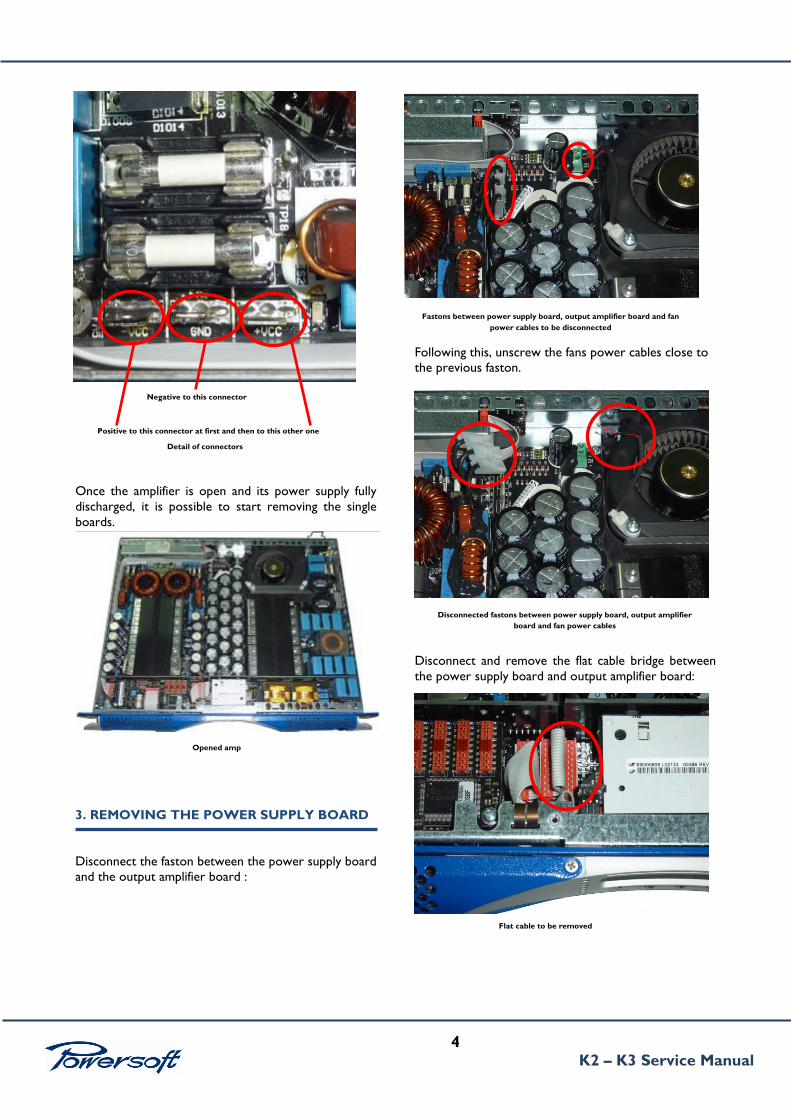
Once the amplifier is open and its power supply fully
discharged, it is possible to start removing the single
boards.
3. REMOVING THE POWER SUPPLY BOARD
Disconnect the faston between the power supply board
and the output amplifier board :
Following this, unscrew the fans power cables close to
the previous faston.
Disconnect and remove the flat cable bridge between
the power supply board and output amplifier board:
Detail of connectors
Negative to this connector
Positive to this connector at first and then to this other one
Opened amp
Fastons between power supply board, output amplifier board and fan
power cables to be disconnected
Disconnected fastons between power supply board, output amplifier
board and fan power cables
Flat cable to be removed
5
K2 – K3 Service Manual
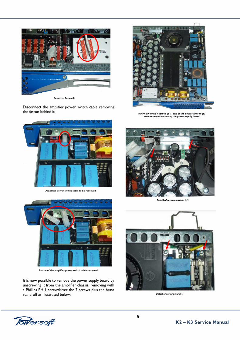
Disconnect the amplifier power switch cable removing
the faston behind it:
It is now possible to remove the power supply board by
unscrewing it from the amplifier chassis, removing with
a Phillips PH 1 screwdriver the 7 screws plus the brass
stand-off as illustrated below:
Overview of the 7 screws (1-7) and of the brass stand-off (8)
to unscrew for removing the power supply board
Removed flat cable
Amplifier power switch cable to be removed
Detail of screws number 1-2
Detail of screws 3 and 4
Faston of the amplifier power switch cable removed

6
K2 – K3 Service Manual
Once all the 8 screws have been removed, remove the
power supply board heat sink screws with an M3
hexagonal key:
Detail of screw number 5
Detail of screw number 6
Detail of screw number 7
Detail of brass stand-off (screw number 8)
Heat sink screws to be removed

7
K2 – K3 Service Manual
Now remove the mains plug holder by pressing on its
sides; then remove the mains socket screws:
Proceed in unscrewing the nut that holds the earth
ground cable behind the mains connector:
Now remove the rear panel:
Heat sink screws removed
Mains connector screws to be removed
Mains connector screws removed
Earth ground nut to be removed
Detached rear panel
Rear panel screws to be removed
8
K2 – K3 Service Manual
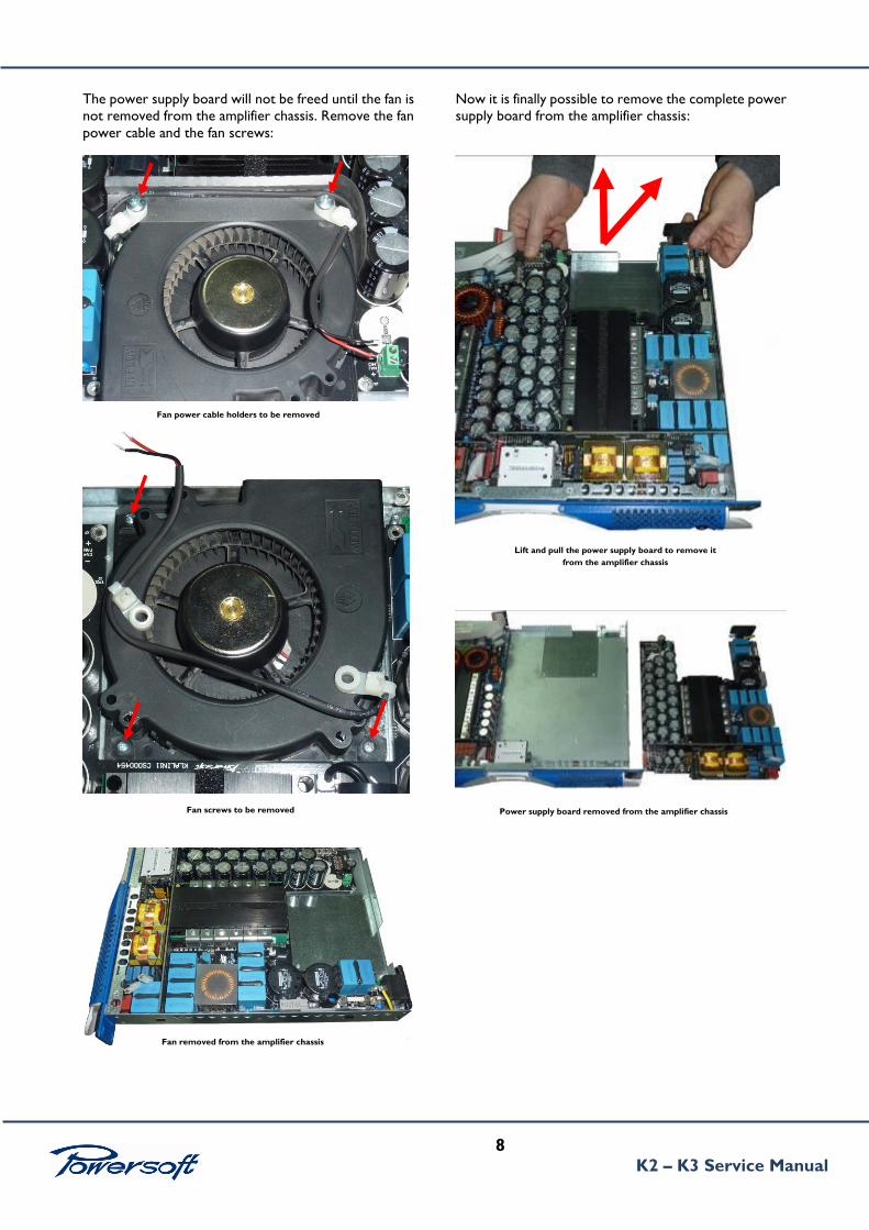
The power supply board will not be freed until the fan is
not removed from the amplifier chassis. Remove the fan
power cable and the fan screws:
Now it is finally possible to remove the complete power
supply board from the amplifier chassis:
Fan screws to be removed
Fan power cable holders to be removed
Fan removed from the amplifier chassis
Power supply board removed from the amplifier chassis
Lift and pull the power supply board to remove it
from the amplifier chassis

9
K2 – K3 Service Manual
4. REMOVING THE AMPLIFIER OUTPUT
BOARD
Before removing the amplifier output board, please
proceed in discharging the power supply capacitors as
explained in chapter 2.
Start from unscrewing the rear panel connectors
removing the mains connector screws and plug holder
as in the images below:
proceed in removing the all rear panel by unscrewing the
screws as marked in the images below
Now remove the two flat cables between the power
supply board and the amplifier output board:
Remove the nuts that hold the amplifier output board
heat sink:
Mains connector screws to be removed
Removed mains connector screws
Rear panel screws to be removed
Detached rear panel
Flat cable to be removed
Flat cable removed
Unscrew this nut
10
K2 – K3 Service Manual
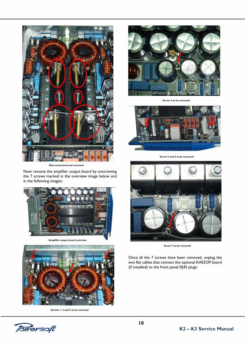
Now remove the amplifier output board by unscrewing
the 7 screws marked in the overview image below and
in the following images:
Once all the 7 screws have been removed, unplug the
two flat cables that connect the optional KAESOP board
(if installed) to the front panel RJ45 plugs:
1
2
3 4 5
6 7
Nuts unscrewed and removed
Screws 1, 2 and 3 to be removed
Amplifier output board overview
Screw 4 to be removed
Screw 5 and 6 to be removed
Screw 7 to be removed
11
K2 – K3 Service Manual
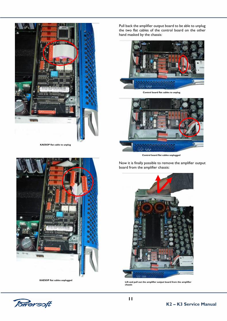
Pull back the amplifier output board to be able to unplug
the two flat cables of the control board on the other
hand masked by the chassis:
Now it is finally possible to remove the amplifier output
board from the amplifier chassis:
Lift and pull out the amplifier output board from the amplifier
chassis
KAESOP flat cable to unplug
KAESOP flat cables unplugged
Control board flat cables to unplug
Control board flat cables unplugged
12
K2 – K3 Service Manual
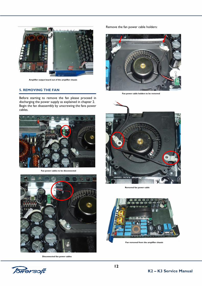
5. REMOVING THE FAN
Before starting to remove the fan please proceed in
discharging the power supply as explained in chapter 2.
Begin the fan disassembly by unscrewing the fans power
cables.
Remove the fan power cable holders:
Amplifier output board out of the amplifier chassis
Fan power cables to be disconnected
Disconnected fan power cables
Fan removed from the amplifier chassis
Removed fan power cable
Fan power cable holders to be removed

13
K2 – K3 Service Manual
6. REMOVING THE DISPLAY (K-FRONT)
Before removing the display, discharge the power supply
capacitors as explained in chapter 2.
Remove the faston that connects the amplifier power
switch:
Now remove the front panel left and right ears:
Remove the left and right protection plates:
The front panel is now free from the amplifier chassis.
Remove the display from the front panel by unscrewing the
four screws seen below:
Amplifier power switch cable to be disconnected
Disconnected faston of the amplifier power switch cable
Screw for removing left ear
Screws for removing the protection plates
Front panel removed from the amplifier chassis
Unplug these two flat cables from the display
These four screws needs to be removed to free the display
Screw for removing right ear

14
K2 – K3 Service Manual
7. INSTRUMENTS AND TOOLS FOR TESTING
DC POWER SUPPLY 0-50 Vcc f.s. 5 A.
DC POWER SUPPLY +/- 30Vcc 0-3 A.
FUNCTION GENERATOR OR CD
PLAYER.
OSCILLOSCOPE DOUBLE TRACE. (IT
MUST BE DISCONNECTED FROM THE
GROUND)
DIGITAL MULTIMETER.
BOOST VOLTAGE CABLE (CB000081)
VOLTAGE AUXILIARY CABLE
(CB000077)
8. FIRMWARE UPDATE PROCEDURE
There is no need to update the amp’s firmware when
replacing power supply boards.
The following will illustrate actions to be undertaken in
case of amplifier or K front boards replacement (see K
front de-mounting procedure at the end of this chapter
if needed).
Due to the fact that the amplifier model type is stored
in the k front board and that this instructs the amplifier
control board, both boards must run the same firmware
version.
Should the system detect a different firmware version in
the 2 boards at power on, the LCD display will show the
message error “NO LINK”.
To avoid this, we suggest updating to the latest release
all K amps DSP you receive for service. To help solve
this “NO LINK” error easily, we can also ship a
FIRMWARE UPDATE CARD (Powersoft code
PC000112).
K amps without DSP DO NOT NEED TO BE
UPGRADED.
FIRMWARE UPDATE procedure for K Series
Main functional parts of K Series amplifiers:
1. KFRONT = microcontroller that handles the front
panel interface (4 pushbuttons + display)
2. KCNTRL = microcontroller that supervises the
amplifier and power supply if DSP is installed
3. KDSP = microcontroller that handles the DSP
parameters
4. SHARC = signal processor
5. The FW update procedure updates the KFRONT,
then the KDSP, then the KCNTRL, and finally the
SHARC.
UPDATING AMPLIFIER (MAIN)
1. Turn the amplifier off
2. Insert the firmware smartcard. The upper code is the
FW revision number (e.g. 3.8.6-161). The bottom
code is the KDSP and SHARC revision number (e.g.
3.8.6-1406). Contacts on bottom.
3. Press the first and second push-buttons on the left
hand side of the front panel. Keep them pressed
(with one hand)
4. With the other hand, turn the amplifier on and wait
3-6 seconds.
5. Right after the fan test (full throttle blow), when the
yellow LEDs on the panel begin blinking, you can
release the buttons. The KFRONT panel monitors
the update process.
6. After about 4 minutes, a message box (if you are
upgrading from a 2.0.x firmware release) appears,
telling you that the current settings are lost, and that
you should verify the settings after the update.
Please check your amplifier settings after the
update. Updating from a 2.94.x or 3.x.x should
however maintain your settings.
Plugs 4mm
1
2
AMP CPC Mains 3 way
Display removed from front panel
Molex 3 pin female 2,54 Plugs 4mm
15
K2 – K3 Service Manual
7. If a KDSP (i.e., an optional DSP board) is present, the
KDSP update begins, its progress indicated by a
progress bar. After about 4 minutes the update is
complete. If a KDSP is NOT present, a START
ERROR message is displayed, requiring a BACK
push-button confirmation.
8. The KCNTRL update begins, its progress mapped by
a progress bar. After about 2 minutes the update is
complete.
9. Finally, a message asking you if you want to update
the SHARC DSP is displayed. By pressing OK the
SHARC DSP is updated. The update lasts as long as
15 minutes and works only if the amplifier is powered
from the mains (NOT from a PowerHub!);
therefore, take care in assuring that the mains supply
is not disconnected during the above process.
10. Verify the update: go to Setup->Hardware Info,
press more, the following should appear:
KFRONT: X.Y.Z – B KCNTRL: X.Y.Z – B KDSP:
X.Y.Z – S
WHERE: X.Y.Z is firmware version, B is the build
number (meaningless) and S is the SHARC firmware
version.
CAUTION:
If the update process terminates before
completion, you must repeat the process starting
from point 1), because you could have 2 different
FW versions on your boards. This could cause the
amplifier to malfunction.
Always check that the update was successfully
completed as explained on point 10.
9. REMOVING THE CONTROL BOARD (K-
CNTRL)
To remove the amp control board please proceed in
discharging the power supply as explained in chapter 2.
Remove the 3 screws over the board as in the picture
below:
Extract care the amp board with care.
Once the control board is replaced, firmware reinstall
illustrated in chapter 8 is mandatory. Once the firmware
is reinstalled, set the desired max output voltage by
following the on display indications:
Menu → setting → amplifier setting → Max output
voltage → setting the value with the two ± button.
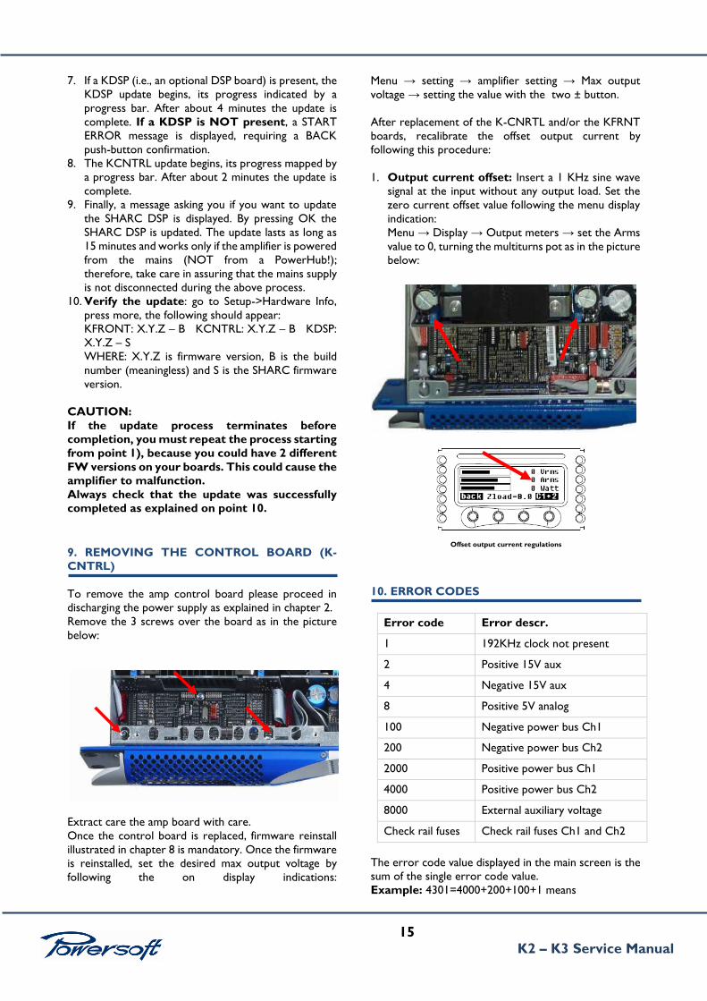
After replacement of the K-CNRTL and/or the KFRNT
boards, recalibrate the offset output current by
following this procedure:
1. Output current offset: Insert a 1 KHz sine wave
signal at the input without any output load. Set the
zero current offset value following the menu display
indication:
Menu → Display → Output meters → set the Arms
value to 0, turning the multiturns pot as in the picture
below:
10. ERROR CODES
Error code Error descr.
1 192KHz clock not present
2 Positive 15V aux
4 Negative 15V aux
8 Positive 5V analog
100 Negative power bus Ch1
200 Negative power bus Ch2
2000 Positive power bus Ch1
4000 Positive power bus Ch2
8000 External auxiliary voltage
Check rail fuses Check rail fuses Ch1 and Ch2
The error code value displayed in the main screen is the
sum of the single error code value.
Example: 4301=4000+200+100+1 means
Offset output current regulations
16
K2 – K3 Service Manual
Positive power bus Ch2 +
Negative power bus Ch2 +
Negative power bus Ch1 +
192 KHz clock not present

17
K2 – K3 Service Manual
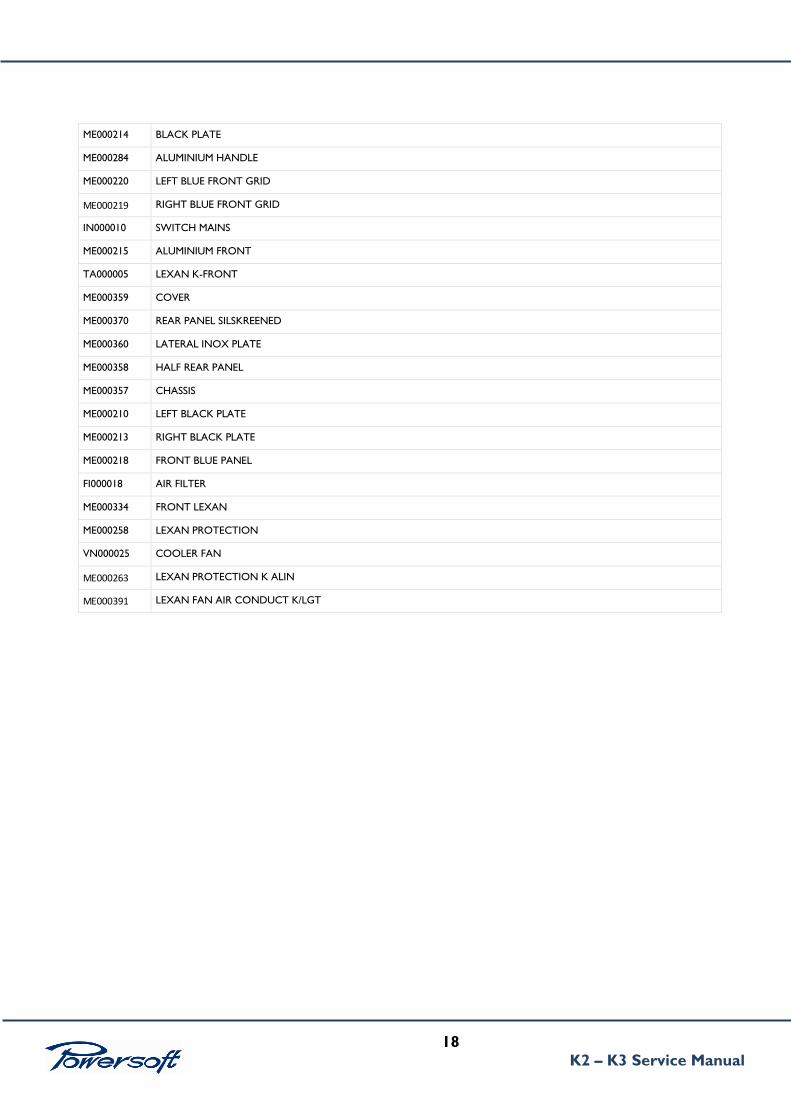
11. MECHANICAL PARTS
18
K2 – K3 Service Manual
ME000214 BLACK PLATE
ME000284 ALUMINIUM HANDLE
ME000220 LEFT BLUE FRONT GRID
ME000219 RIGHT BLUE FRONT GRID
IN000010 SWITCH MAINS
ME000215 ALUMINIUM FRONT
TA000005 LEXAN K-FRONT
ME000359 COVER
ME000370 REAR PANEL SILSKREENED
ME000360 LATERAL INOX PLATE
ME000358 HALF REAR PANEL
ME000357 CHASSIS
ME000210 LEFT BLACK PLATE
ME000213 RIGHT BLACK PLATE
ME000218 FRONT BLUE PANEL
FI000018 AIR FILTER
ME000334 FRONT LEXAN
ME000258 LEXAN PROTECTION
VN000025 COOLER FAN
ME000263 LEXAN PROTECTION K ALIN
ME000391 LEXAN FAN AIR CONDUCT K/LGT

19
K2 – K3 Service Manual
12. K2-K3 SPARE PARTS LIST
KALIN
Part Number Description PCB position
SMD00611 K/LGT/ALIN/12+TEST+HSINK
RES00120 R52, R53
CA000200 ELET.1000UF 200V 25X35 SNAP IN 85° P10 C50 C51 C52 C53 C54 C55 C56 C57 C58 C59 C60 C61 C62 C63 C64 C65 C66 C67
C68 C69 C71 C72
DI000070 IRC 30EPH06 D9
DI000083 GSIB1580 PONTE A DIODI D1 D2
DIS00007 5.1 VZ MMSZ5231B SOD123 D14
DIS00033 US1J DO214AC D11,D13
DIS00030 13 VZ SML4743 DO214AC D12
DIS00021 SS14 -E3/61T Schottky_Barrier_Rectifier D44
DIS00026 BAS28 High_Speed_Double_Diode D19
DIS00009 15 VZ MMSZ5245B SOD123 D71 D72
DIS00039 15 VZ 1W SML4744 DO214AC D10 D18 D60
DS000009 HTSK-AL-OSA56-145 OXN HORZ. FINS REV.02 Taric.
76169990 90 SM000645
FU000032 Fuse 15A 250VDc (6x32mm) Fast UL Serie 3AB Fast Series F1 F2
ICS00019 IR2156S SOIC14 BALLAST_CONTROL_IC SMD U2
ICS00120 IRC IR1150ISTRPbF PFC One Cycle Control PFC IC U1
IG000003 IRG4PC50UDPbF N-Channel Gate Bipolar Trans IGBT 600V 50A
TO-247AC Q11 Q12
IN000010 Switch Rocker Single Pole SP-ON 6A 250Vac 13-Round Body
(Ø=20.2)mm Color ME364
IS000041 HI-FLOW300 145x32 AMPL.KALIN.LGT $1,25 1 pc. X channel
ML000001 MOLLE Q&D INOX 2 pc. X channel
ML000007 MOLLE K&Q&D INOX SP. 1.2 13 pc. X channel
MO000038 FCH47N60F_F133 NChannel_SuperFET Vds=600V
ID@25°C=47A Pd=417W TO-247 PTH Q3 Q4 Q5
RE000335 NTC 2 Ohm 12A 20% P5.1W (21x7x28)mm Pitch 7.5mm S364
Series CONF(100) R54
TO000099.2 "K-LGT" RES.CONV.TRASF.135015 E42/21/15 3C92 CSA from
20/09 Furukawa T5 T6 (ORA SONO CSA)
TR000003 BDW93CFP NPN_Darlington_Power_Transistor Vceo=100V Pd=33W 100<hFE@10A(Ic)3V(Vce)<20000 TO220FP PTH
Q13 Q14
TRS00009 PBSS5320T PNP_Transistor Vceo=-20V Ic=-2A Pd=300mW(su
footprint standard) hfe=220_max SOT23 SMD Q2 Q8 Q10
TRS00010 PBSS4320T NPN_Transistor Vceo=20V Ic=2A Pd=300mW(su
footprint standard) hfe=220_max SOT23 SMD Q1 Q7 Q9
VN000025 ADDA AB1212XB-Y01 12V 1.4A Ieff=1.12A v=3100rpm
Airflow_Max=36.323CFM N=57dB/A W120.5D120.5H32mm SM000645
VR000007 VARISTOR S20K385 EPCOS CONF(200) RV1

20
K2 – K3 Service Manual
KAMIN
SMD00565 K/LGT/AMIN/12+DRIVER+CNTRL+COLL+HSINK
CA000257 EL.330UF200V 18X35.5 105GR LESR 7,5mm Lead spacing
3,32A Ripple 10.000hrs
C1001 C1002 C1003 C1004 C1005 C1006 C2001 C2002 C2003 C2004
C2005 C2006
DI000073 IXS DSEC29-06AC D1005 D1006 D2005 D2006
DIS00037 FFB20UP20S 20A 200V D2 PACK D1003 D1004 D2003 D2004
FU000026 Fuse 10A 250VDc (5x20mm) Time Delay F1001A F1002A F2001A F2002A
IN000012 Dip-Switch 10Position BCD 0.4VAC, DC20Vmax Series Body
(10x10)mm CRD SW3 SW4
IS000041 HI-FLOW300 145x32 AMPL.KALIN.LGT $1,25 1 pc. X channel
ML000001 MOLLE Q&D INOX 4 pc. X channel
ML000007 MOLLE K&Q&D INOX SP. 1.2 12 pc. X channel
MO000039 N-Channel SuperFET Vds 600V Id 141A 417W TO-247
FDH45N50F-133 Q1001 Q1002 Q1003 Q1004 Q2001
Q2002 Q2003 Q2004
SM000291 K/STD/DRIVER/12 rev.01 del 03/11/2004
SM000526 K/LGT/RES/10
SM000741 K/LGT/CONTROL/16 rev.02 del 27/06/2008
SO000004 P6KE18CA Bidirectional Vbr=18V Ipp=24A Pd=5W Ppp=600W
DO15 PTH RV1001 RV1002 RV2001 RV2002
SM000635B K/STD/FRONT/15 senza SM000326


![BONUS ARAN 9219 - Knitting Bee › wp-content › uploads › 2016 › 09 › ara… · 11:14:16:19] times, k2, p8, * k2, (p2, k3) twice, p4, k4, p4, (k3, p2) twice, k2, * p8, k2,](https://static.fdocuments.in/doc/165x107/60bdfede8f92fe7a6c32e53f/bonus-aran-9219-knitting-bee-a-wp-content-a-uploads-a-2016-a-09-a-ara.jpg)

![Trial Penang SPM 2013 BIOLOGY K2 K3 [SCAN]](https://static.fdocuments.in/doc/165x107/577cd7621a28ab9e789ed413/trial-penang-spm-2013-biology-k2-k3-scan.jpg)


![Trial Penang SPM 2013 CHEMISTRY K2 K3 [SCAN]](https://static.fdocuments.in/doc/165x107/577cd7621a28ab9e789ed416/trial-penang-spm-2013-chemistry-k2-k3-scan.jpg)


![Trial Penang SPM 2013 PHYSICS K1 K2 K3 SKEMA [SCAN]](https://static.fdocuments.in/doc/165x107/577cd7621a28ab9e789ed419/trial-penang-spm-2013-physics-k1-k2-k3-skema-scan.jpg)
