k Study of Methods Used in - USGS · k Study of Methods Used in ... 'Report No. 5 LABORATORY...
100
Transcript of k Study of Methods Used in - USGS · k Study of Methods Used in ... 'Report No. 5 LABORATORY...


k Study of Methods Used i n
MEASLREMENT AND ANALYSIS OF SEDIMENT MADS I N STREAMS
Planned and conducted j o i n t l y by
Tennessee Volley Authority, Corps of Engineers,
Department of kgricul turo, G o o l o ~ i c a l Survey,
Bureau of Recl&mation, Indian Service, and
Iowa I n s t i t u t e of Hydraulic Research
'Report No. 5
LABORATORY INVESTIGATIONS OF SUSPENDED SEDIMENT SAMPLERS
Published a t
S t . Paul TJ. S. Engineer D i s t r i c t Sub-office Hydraulic Laboratory, University of Iowa
Iowa City, Iowa
f
November 1941
Reports 2
The cooperative study of methods used in
MEASUREMENT AND ANALYSIS OF SEDIMENT LOADS IN STREAMS
covers phases indicated by the following report titles.
Report-No. 1
FIELD PUCTICE AND EQUIPMENT USED IN SAMPLING SUSPENDED SEDIMENT
Re~ort .No. 2
EQUIPMENT USED FOR SAMPLING BED-LOAD AND BED MATERIAL
Report No. 3
ANALYTICAL STUDY OF METHODS OF SAMPLING SUSPENDED SEDIMENT
Report No. 4
METHODS OF ANALYZING SEDIMENT SAMPLES
Report No. 5
LABORATORY INVESTIGATIONS OF SUSPENDED SEDIMENT SAMPLERS

SYNOPSIS
This r e p o r t p re sen t s t h e r e s u l t s of experimental s t u d i e s of sus-
pended sediment samplers. Various forms of simple i n t a k e tubes and
t y p i c a l suspended sediment sampler i n t a k e s were t e s t e d t o eva lua te e r r o r s
i n t h e sediment concent ra t ion of samples due t o adverse sampler en t rance
condi t ions , depos i t ion of sediment with flow through a hor i zon ta l cy l in -
de r , and l o s s o f s e d i m e n t i n t r a n s f e r r i n g t h e samples t o o t h e r conta iners .
Tes t s were maue with f i v e r ep resen ta t ive slow f i l l i n g samplers t o
de tern ine t h e i r f i l l i n g c h a r a c t e r i s t i c s under var ious condi t ions of
stream v e l o c i t y , sampling depth, and sampler operat ion.
Table of Cnhtents 4
TABLE OF CONTENTS
I . INTRODUCTION
1 S c o p e o f p r o j e c t . . . . . . . . . . . . . . . . . . . . . . . . 9
2 Purpose of expe~imenta l study .of san.,lers . . . . . . . . . . . 1 0
3 Methods of study . . . . . . . . . . . . . . . . . . . . . . . 11 4 Author i tyandpersonne l . . . . . . . . . . . . . . . . . . . . 1 2
I1 . TEST EQUIPMENT AND EXPERIMENTAL MATERIAL
5 Test equipment . . . . . . . . . . . . . . . . . . . . . . . . . 14
6 Accessories f o r operat ing the c i r c u l a t i n g system . . . . . . . 18
7 Sampling apparatus used i n study of sampling ac t ion . . . . . . 1 9
8 Water and sediment used i n t e s t s of sampling ac t ion . . . . . . 2 2
9 Operating c h a r a c t e r i s t i c s of c i r c u l a t i n g system . . . . . . . . 25
I11 . TESTS OF SAMPLER ENTRANCE CONDITIONS
10 Flow pa t t e rns a t the entrance . . . . . . . . . . . . . . . . . 31
. . . . . . . . . 11 General procedure i n t e s t i n g sampler intakes 33
12 O u t l i n e o f t e s t s . . . . . . . . . . . . . . . . . . . . . . . 35
1 3 Technique i n co l l ec t ing and analyzing samples . . . . . . . . . 35
14 Errors i n sediment concentration of samples col lec ted with s t w a r d sampler nozzle . . . . . . . . . . . . . . . . . . . . 37
1 5 Effect of small deviat ions from normal nozzle o r i en ta t ion Dn e r r o r s i n sediment concentration . . . . . . . . . . . . . . . 41
16 Ef fec t of s i z e of nozzle mouth on e r r o r s i n sediment concen- t r a t i o n . . . . . . . . . . . . . . . . . . . . . . . . . . . . . 42
17 Ef fec t of sampler nose design on e r r o r s i n sediment concen- t r a t i o n . . . . . . . . . . . . . . . . . . . . . . . . . . . . 44
18 E f f e c t of f l a p valves a t sampler in takes . . . . . . . . . . . 53
19 Errors i n sediment concentration of samples col lec ted with nozzles i n v e r t i c a l pos i t ion . . . . . . . . . . . . . . . . . 55
5 . ... ... .-
Table of Contents
Sect ion
20 Er ro r s i n sediment concentrat ion of samples co l l ec ted through sampler in take hor i zon ta l and normal t o flow . . . . . . . . . 59
I V . DEPOSITION OF SEDIMENT IN INSTANTANEOUS HORIZONTAL SAMPLER
21 Scope of deposi t ion study . . . . . . . . . . . . . . . . . . . 68
22 Tes tp rocedure . . . . . . . . . . . . . . . . . . . . . . . . 69
23 T e s t r e s u l t s . . . . . . . . . . . . . . . . . . . . . . . . . 69
V . INACCURACIES DUE TO SEDIMENT ADHERING TO SAMPLER
24 Source of e r r o r i n t r a n s f e r r i n g samples . . . . . . . 72
25 Tes tp rocedure . . . . . . . . . . . . . . . . . . . . . . . . 72
26 T e s t r e s u l t s . . . . . . . . . . . . . . . . . . . . . . . . . 73
V I . FILLING CHARACTERISTICS OF SLOW FILLING SILYPLERS
27 N a t u r e o f t e s t s . . . . . . . . . . . . . . . . . . . . . . . . 76
28 Samplers t e s t ed and t h e i r a l t e r a t i o n s f o r t e s t . . . . . . . . 76
29 Procedure of t e s t s . . . . . . . . . . . . . . . . . . . . . . 81
30 F i l l i n g c h a r a c t e r i s t i c s . . . . . . . . . . . . . . . . . . . . 82
31 Effec t iveness of f i l l i n g r a t e adjustmonte . . . . . . . . . . . 87
32' E f f e c t of lowering and r a i s i n g t h e Colorado sampler upon i t s f i l l i n g cba rac te r iS t i c s . . . . . . . . . . . . . . . . . . . . 88
53 Effec t of stream ve loc i ty on f i l l i n g r a t e s . . . . . . . . . . 92
1 SUMMARY AND CONCLUSIONS
34 Summary of sampler s tud ies . . . . . . . . . . . . . . . . . . 94
35 Study of' sampler entrance condit ions . . . . . . . . . . . . . 95
36 Flow through hor i zon ta l cy l inders . . . . . . . . . . . . . . . 97
37 Loss of sediment i n sample t r a n s f e r from non-removable con- t a i n e r s . . . . . . . . . . . . . . . . . . . . . . . . . . . . 97
. . . . . . . 38 F i l l i n g c h a r a c t e r i s t i c s of slow f i l l i n g samplers 98

L i s t of I l l u s t r a t i o n s 6
LIST OF 1LLUST.SATIONS
1 Equipment f o r t e s t i n g sampler intake condit ions . . . . . . . . 1 5
2 Sampling apraratus . . . . . . . . . . . . . . . . . . . . . . 21
3 Size gradations of t e s t mater ia ls . . . . . . . . . . . . . . . 24
4 F a l l v e l o c i t i e s of t e s t mater ia ls . . . . . . . . . . . . . . . 24
5 Velocity contours at sampling s t a t i o n . . . . . . . . . . . . . 26
6 Fluctuat ions of sediment concentration a t dup l i ca te sampling points . . . . . . . . . . . . . . . . . . . . . . . . . . . . 27
7 Sediment d i s t r i b u t i o n a t sampling s t a t i o n . . . . . . . . . . . 29
8 Flow pa t t e rns at mouth of sampler in take . . . . . . . . . . . 32
9 Standard nozzle intake diameter 0.25 i n . . . . . . . . . . . . 34
10 Ef fec t of sampling r a t e on sediment concentration; 0.45-nun. sediment . . . . . . . . . . . . . . . . . . . . . . . . . . . 38
E f f e c t of sampling r a t e on sediment concentration; 0.15-nun. sediment . . . . . . . . . . . . . . . . . . . . . . . . . . . Effec t of sampling r a t e on sediment concentration; 0.06-nun. and 0.01-mm. sediments . . . . . . . . . . . . . . . . . . . . Effec t of stream ve loc i ty on e r r o r s i n sediment concentrat ion
Relat ion of sediment s i z e t o e r r o r s i n sediment concentration
E f f e c t of small devia t ions from normal nozzle o r i en ta t ion on e r r o r s i n sediment concentration . . . . . . . . . . . . . . . E f f e c t of nozzle s i z e on e r r o r s i n sediment concentration . . . Nozzles modified a t mouth from standard design . . . . . . . . Effec t of round edged nozzle mouth on e r r o r s i n sediment c o n c e n t r a t i o n . . . . . . . . . . . . . . . . . . . . . . . . . Effec t of outside beveled nozzle mouth on e r r o r s i n sediment c o n c e n t r a t i o n . . . . . . . . . . . . . . . . . . . . . . . . .
E f fec t of ins ide beveled nozzle mouth on e r r o r s i n sediment concentration . . . . . . . . . . . . . . . . . . . . . . . . .

7 L i s t of I l l u s t r a t i o n s
Figure
21 Blunt nose sampler i n t akes . . . . . . . . . . . . . . . . . . 48
22 E f f e c t of b lunt nose sampler i n t a k e s on e r r o r s i n sediment concent ra t ion . . . . . . . . . . . . . . . . . . . . . . . . . 49
23 Replica of Rock Is land t ime- in tegra t ing sampler nose . . . . . 51
24 Ef fec t of Rock I s l and sampler nose on e r r o r s i n sediment concent ra t ion . . . . . . . . . . . . . . . . . . . . . . . . . 52
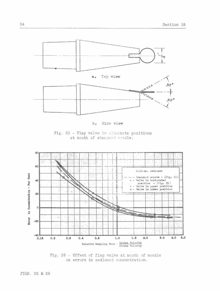
25 Flap valve i n a l t e r n a t e p o s i t i o n s a t mouth of s tandard nozzle . 54
26 Ef fec t of f l a p valve a t mouth of nozzle on e r r o r s i n sediment concent ra t ion . . . . . . . . . . . . . . . . . . . . . . . . . 54
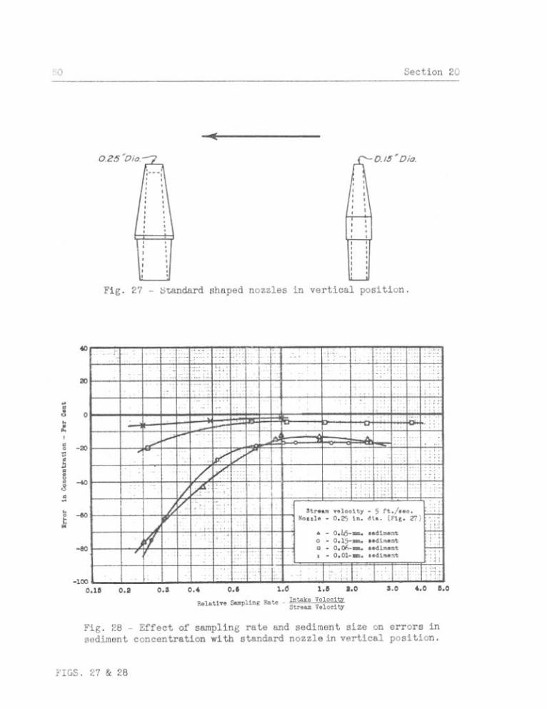
27 Standard shaped nozzles i n v e r t i c a l pos i t i on . . . . . . . . . 60
28 Ef fec t of sampling r a t e and sediment s i z e on e r r o r s i n sed i - ment concent ra t ion with s tandard nozzle i n v e r t i c a l pos i t i on . 60
29 Ef fec t of s t ream v e l o c i t y on e r r o r s i n sediment concent ra t ion with s tandard nozzle i n v e r t i c a l pos i t ion . . . . . . . . . . . 6 1
30 Ef fec t of s i z e of sampler mouth on e r r b r s i n sediment concen-. t r a t i o n with s?: ... nozzle i n v e r t i c a l p o s i t i o n . . . . . . . 61
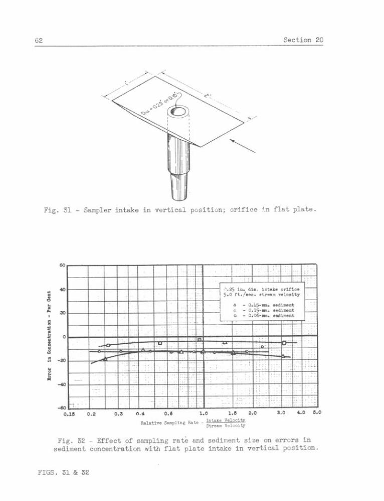
31 Sampler i n t a k e i n v e r t i c a l pos i t i on ; o r i f i c e i n f l a t p l a t e . . 62
32 Ef fec t of sampling r a t e and sediment s i z e on e r r o r s i n sediment concent ra t icn with f l a t p l a t e in t ake i n v e r t i c a l pos i t ion . . . 62
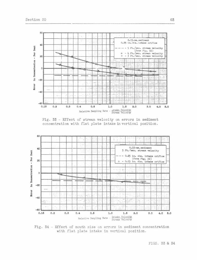
I 3 E f f e c t of s t ream v e l o c i t y on e r r o r s i n sediment concent ra t ion with f l a t p l a t e in t ake i n v e r t i c a l pos i t ion . . . . . . . . . . 65
34 Ef fec t of mouth s i z e on e r r o r s i n sediment concent ra t ion witin f l a t p l a t e i n t a k e i n v e r t i c a l pos i t ion . . . . . . . . . . . . 63
35 Mushroom shaped sampler i n t a k e i n v e r t i c a l pos i t i on . . . . . . 64
36 Ef fec t of sampling r a t e on e r r o r s i n sedinent concent ra t ion with mushroom shaped i n t a k e i n v e r t i c a l pos i t i on . . . . . . . 64
37 F l a t p l a t e sampler in take ho r i zon ta l and normal t o flow . . . . 65
38 Ef fec t of sampling r a t e , sediment s i z e and mouth diameter on e r r o r s i n sediment concent ra t ion with f l a t p l a t e in t ake ho r i - zontal and normal t o flow . . . . . . . . . . . . . . . . . . . 57
39 E f f e c t of stream ve loc i ty on e r r o r s i n sediment concent ra t ion with f l a t p l a t e in t ake ho r i zon ta l and normal t o f low . . . . . 67

List of I l l u s t r a t i o n s 8
. . . . . . . 40 United S t a t e s Geological Survey Colorado sampler 77
41 S t raubsample r . . . . . . . . . . . . . . . . . . . . . . . . 78
42 Sketch of F r a z i e r sampler showing method of operat ion . . . . . 78
43 Omahasampler . . . . . . . . . . . . . . . . . . . . . . . . . 79
44 Rock Is land sampler . . . . . . . . . . . . . . . . . . . . . . 80
45 Method of suspending samplers i n flume . . . . . . . . . . . . 82
46 F i l l i n g c h a r a c t e r i s t i c s of samplers i n s t i l l water . . . . . 83
47 I n i t i a l inrush i n t o slow f i l l i n g r i g i d conta iner samplers . . . 85
48 E f f e c t of s i z e of opening i n F r a z i e r sampler upon f i l l i n g r a t e 89
49 E f f e c t of a i r exhaust adjustment upon f i l l i n g r a t e of Rock I s l and sampler i n s t i l l water . . . . . . . . . . . . . . . . . 89
50 F i l l i n g c h a r a c t e r i s t i c s of Colorado sampler with v e r t i c a l move- ment i n s t i l l water . . . . . . . . . . . . . . . . . . . . . . 90
. . . . . . . . . 5 1 Ef fec t of stream ve loc i ty upon f i l l i n g r a t e s 93
LIST OF TABLES
Table
1 Test data.. sediment depos i t ion i n hor izonta l cy l inde r . . . . . 70
2 Sediment -etained i n samplers; per cent by weight . . . . . . . 74

Sect ion 1 - 9
LABO-MTORY INVESTIGATIONS
OF SUSPENDED SEDIMENT SAMPLERS
I . INTRODUCTION
1. Scope of project--Measurement of the q u a n t i t y and charac te r of
sediment t ranspor ted by streams i s an important a c t i v i t y common t o r i v e r
maintenance and development, stream discharge measurement, e ros ion con-
t r o l , i r r i g a t i o n , and hydro-electr ic development. A cooperat ive p ro jec t
has been sponsored by a number of Government agencies t o s t u d y the va r ious
methods and types of equipment used i n t h e measurement of sediment loads ,
with t h e u l t ima te aim of improving and s tandardiz ing them so that more
analogous d a t a w i l l be secured.
From t h e s tandpoint ofsampling equipment and technique, t h e movement
of sediment has been c l a s s i f i e d a s suspended load and bed load. The b a s i c
d i f f e r e n c e i n t h e i r measurement i s t h a t the former i s determined from a
sample as the weight of s o l i d s per u n i t volume of water which, when cor-
r e l a t e d with water d ischarge , w i l l g ive t h e q u a n t i t y o f suspended sediment
t ranspor ted i n a given time, while the bed-lohd i s measured d i r e c t l y as
t h e weight of sediment moving p a s t a u n i t of stream width per u n i t of time.
This p ro jec t was concerned pr imar i ly with t h e problems of suspended sedi -
ment determinations, b u t included, a l s o , a b r i e f review of bed-load and
bed mate r i a l sampling equipment.
The determination of t h e quan t i ty and charac ter of suspended sediment
pass ing a se lec ted stream c ross sec t ion over a period of time, involves
t h e fol lowing phases:
a. Selec t ion of sampling p o i n t s so t h a t t h e samples can be properly co r re la t ed with t h e water discharge and t h e de te r - mination of t h e frequency of sampling.
10 Section 2
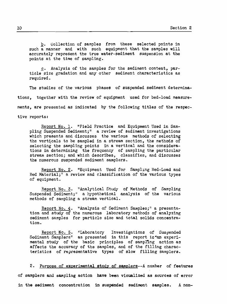
b. Collect ion of samples from these se lec ted po in t s i n such a manner and with such equipment t h a t the samples w i l l accura te ly represent the t r u e water-sediment suspension a t the points a t t h e time of sampling.
c . Analysis of the samples f o r the sediment content , par- t ic le-s ize gradation and any other sediment c h a r a c t e r i s t i c s a s required.
The s tud ies of the var ious phases of suspended sediment determina-
t ions , together with the review of equipment used f o r bed-load measure-
ments, a r e presented as indicated by the fol lowing t i t les of the respec-
t i v e reports:
Report No. 1. "Fie ld Pract ice and Equipment Used i n Sam- pl ing Suspended Sediment;" a review of sediment inves t iga t ions which presents and discusses the various methods of s e l e c t i n g the v e r t i c a l s t o be sampled i n a stream sect ion, the methods of se lec t ing the sampling po in t s i n a v e r t i c a l and the considera- t i o n s i n determining the frequency of sampling the p a r t i c u l a r stream sec t ion ; and which descr ibes , c l a . s s i f i e s , and discusses the numerous suspended sediment samplers.
Report No. 2. "Equipment Used f o r Sampling Bed-Load and Bed Material ;" a. review a.nd c l a s s i f i c a t i o n of the various types of equipment.
Report No. 3. "Analytical Study of Methods of Sampling Suspended Sediment;" a hypothetical a n a l y s i s of the various methods of sampling a stream v e r t i c a l .
Report No. 4 . "Analysis of Sediment Samples;" a presenta- t i o n and study of the numerous laborntory methods of analyzing sediment samples f o r p a r t i c l e s i z e and t o t a l s o l i d s concentra- t ion.
Report No. 5. ltLaboratory Inves t igat ions of Suspended Sediment Samplere" a s presented i n t h i s repor t is'm experi- mental s tudy of the bas ic p r inc ip les of samplfng ac t ion as a f f e c t s the accuracy of the samples, and of the f i l l i n g charac- t e r i s t i c s of r e s resen ta t ive types of slow f i l l i n g samplers.
2. Purpose of experimental s tudy ~f samplers--A number of f e a t u r e s
of samplers and aampiing ac t ion have been visual ized as sources of e r r o r
i n t h e sediment concentrat ion i n suspended sediment samples. A non-

r ep resen ta t ive sample may r e s u l t from adverse entrance condit ions i n t o a
sampler, from accumulation of sediment i n the sample container , o r from
l o s s of sediment i n t r a n s f e r r i n g a sample. These fac to r s , and the magni-
tude of t h e i r e f f e c t s upon the samples, were inves t iga ted experimentally
i n t h i s labora tory study.
From the review of sediment inves t iga t ions a s presented i n Report
No. 1, i t was evident t h a t there was a ser ious lack of exact knowledge of
t h e f i l l i n g c h a r a c t e r i s t i c s of slow f i l l i n g samplers, p a r t i c u l a r l y the
magnitude of t h e i r f i l l i n g r a t e s under various sampling condit ions. The
experimental study was conducted t o provide t h i s bas ic information neces-
sary i n the study of the f i e l d operation, i n the ana lys i s of e r r o r s re..
s u l t i n g from the f i l l i n g ac t ion , and i n the design of a sampler.
3 . Methods of studx--The ana lys i s of sampler entrance condit ions
cons t i tu ted the major problem i n the study of the e r r o r s i n sediment con-
t e n t of samples. I t required e labora te procedure and equipment and in -
volved the l a r g e s t number of t e s t s . Entrance condit ions were es tabl i shed
which, l o g i c a l l y , would cause e r r o r s , and the magnitude of the e r r o r s
were evaluated, but no attempt was made t o determine the a c t u a l flow
pa t t e rns a t the in takes . Samples were col lec ted from suspensionsofknown
concentrat ion and e r r o r s i n the sample concentrations were a t t r i b u t e d t o
the p a r t i c u l a r entrance condit ions. This procedure involved the c i r cu la -
t i o n of a water-sediment suspension through a closed conduit from which
t e s t and standard samples were col lec ted simultaneously from adjacent
sampling points . The standard samples, col lec ted under the most i d e a l
entrance conditions, were u s e d t o e s t a b l i s h t h e t r u e sediment concentration

12 Sect ion 4
of the suspension a t the sampling po in t , a s no method of computing t h i s
concent ra t ion was devised.
The tendency toward depos i t ion of sediment i n the passage of a sus-
pension through a hor izonta l cyl inderwas r e a d i l y o b s e r v e d i n a t r anspa ren t
cy l inder placed i n the flowing suspension. The phenomenon was s tudied
q u a n t i t a t i v e l y f o r s eve ra l samples which were trapped i n the cy l inder .
To evalua te t h e tendency toward a l o s s of sediment i n a sample
t r a n s f e r , caused by sediment adhering wi th in the samplers, simple, d i r e c t
t e s t s were made. The procedure cons is ted e s s e n t i a l l y of emptying pre-
pared samples of known concentrat ion out of var ious samplers and of
analyzing both the f i n a l sample and the res idue i n t h e sampler.
The s tudy of sampler f i l l i n g c h a r s c t e r i s t i c s , of the var ious slow
f i l l i n g samplers, involved a c t u a l f i l l i n g r a t e measurements under a range
of condi t ions of stream depth, v e l o c i t y , and sampler opera t ion . A number
of the t e s t s were made i n the deep, s t i l l water of an abandoned quarry,
and t h e t e s t s involving stream ve loc i ty were made i n a l a r g e flume a t the
labora tory of t h e Iowa I n s t i t u t e of Hydraulic Research.
4. Authori ty and personnel--The cooperat ive p ro jec t , of which this
study i s a p a r t , was authorized and sponsored informally by t h e fol lowing
Federal Government agencies: the Geological Survey, Indian Serv ice , and
Bureau of Reclamation of the Departmerit of I n t e r i o r ; t h e Flood Control
Coordinating Committee of the Department of Agr icul ture ; the Engineer
Department of the War Department; and the Tennessee Valley Authori ty.
The s t u d i e s were conducted a t the Hydraulic Laboratory of the Iowa
I n s t i t u t e of Hydraulic Research, S t a t e Universi ty of Iowa, under t h e
Section 4 15
supervision of Professor E. W. Lane, consulting engineer. Engaged on the
p ro jec t a s representat ives of t h e i r respective cooperating agencies have
been Cleveland H . Horne, J r . , Engineer Department; Victor A . Koelaer,
Geological Survey; Donald E. Rhinehart, Bureau of Reclamation; Vernon J .
Palmer, Flood Control Coordinating Committee; and Clarence A . Boyll,
Tennessee Valley Authority.
The Iowa City Sub-office of the S t . Paul U. S. Engineer D i s t r i c t
under the d i r ec t i on of Martin E. Nelson, Engineer, a ss i s t ed i n the admin-
i s t r a t i o n of the project , edi ted and published the repor ts and a s s i s t ed
i n the design and construction of equipment and i n the conduct of t e s t s .
14 Sect ion 5 -
11. TEST EQUIPMENT AND EXPERIMENTAL MATERIAL
5. Test equipment--The experimental study of sampler entrance con-
d i t i o n s required the development of spec ia l labora tory equipment which
cons is t -d e s s e n t i a l l y of: a conduit through which a water-sediment sus-
penelon was c i r cu la t ed a s des i red; spec ia l sampling apparatus permi t t ing
t h e c o l l e c t i o n of samples from the c i r c u l a t i n g suspension under ca re fu l ly
cont ro l led sampling condit ions; and regular labora tory equipment f o r
analyzing samples.
No add i t iona l equipment was required f o r the s tudy of sediment de-
pos i t ion i n instantaneous horizontal samplers. For the evaluat ion of t h e
l o s s of sediment i n t r a n s f e r r i n g samples the conta iners of seve ra l common
samplers were used.
The t e s t s of f i l l i n g c h a r a c t e r i s t i c s of samplers were conducted wi th
f i v s r e l a t i v e l y common slow f i l l i n g samplers, including both the bubbling
type and the smooth f i l l i n g type provided wi th separa te a i r exhauste.
The desc r ip t ions of the samplers t e s t e d and the a l t e r a t i o n s t o adapt them
f o r the t e s t s , a r e given i n Sect ion 28. The main add i t iona l equipment
cons is ted of a U . S. Geological Survey type sounding r e e l f o r suspending
t h e samplers, and a Tr ice current meter f o r measuring the stream ve loc i ty
a t t he sampling poin t .
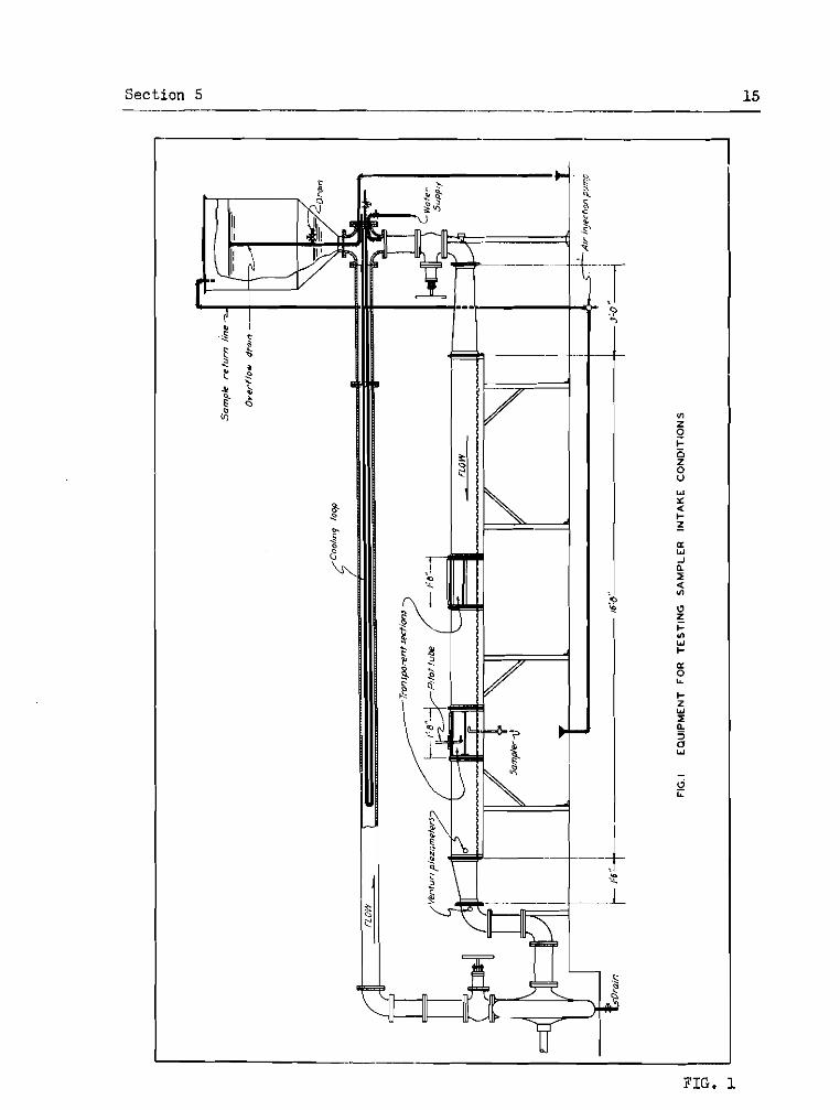
The conduit o r c i r c u l a t i n g system a s shown i n Fig. 1, f o r the s tudy
of sampler entrance conditions, was composed of (1) a hor izonta l , rec-
tangular conduit , 10 by 10 i n . by 16 f t . long, a s the main t e s t i n g and
observat ion sec t ion , (2) a 6-in. cen t r i fuga l sand pump, a t t he downstream
end of the main sec t ion , f o r c i r c u l a t i n g the suspension, ( 3 ) a 6-in.
Section 5 15
I I
FIG. 1

16 Section 5
c y l i n d r i c a l pipe l i n e t o c a r r y the suspension from t h e pump t o the up-
stream end of the main sec t ion , and (4) a r e se rvo i r o r head tank connected
t o the system above the upstream end of t h e main sec t ion .
The main sec t ion , cons i s t ing of t h r e e sec t ions , formed of 1/8 i n .
sheet s t e e l and two t r ansparen t pyral in sec t ions , was b u i l t on a s i n g l e
16 .8-f t . l eng th of 10-in. 15.3-lb. s t e e l channel. The channel, with
f langes turned down, provided the smooth bottom of t h e conduit , and t h e
formed s e c t i o n s were bolted over rubber gaslcets t o t h e f langes of t h e
channel. The two t ransparent sec t ions , b u i l t up of 1/4-in. shee t pyra l in ,
were bol ted t o the adjo in ing s t e e l sec t ions and t o t h e f langes of t h e
channel. They provided observation and t e s t sec t ions , t h e downstream one
being equipped and used as t h e sampling s t a t i o n .
A recondit ioned, 6-in., Morris, cen t r i fuga l sand pump, model 1911,
b e l t dr iven by a 30 hp. e l e c t r i c motor, was used t o c i r c u l a t e t h e suspen-
s ion. It had a maximum capaci ty of 3.8 c .f .s., which provided 5.5 f t . / sec .
v e l o c i t y a t the sampling s t a t i o n . One disadvantage i n the use of t h i s
pump, a f t e r it was-cleaned of r u s t , was the somewhat pulsa t ing na tu re of
i t s discharge.
The tank, connected i n d i r e c t l y i n t o the conduit above t h e upstream
end of the main sec t ion , functioned a s a pressure con t ro l and r e s e r v o i r ,
and provided a means of adding sediment and water t o the suspbnsion t o
replace t h a t withdrawn as samples. I t a l s o served a s a r e se rvo i r i n t o
which the e n t i r e suspension from t h e main sec t ion could be pumped and
saved wnile a l t e r a t i o n s were made a t t h e sampling sec t ion . As t h e c i r -
c u l a t i n g suspension d i d not flow tldrough the tank, t h e water i n t h e tank
normalzy was Wanquil , undisturbed, and f r e e from sediment. The water

pressure i n the tank was transmit ted d i r e c t l y t o t h e system, r e s u l t i n g
i n opera t ing pressures above atmospheric throughout, and thereby prevent-
i n g t h e suct ion o f a i r through small l eaks i n t o t h e c i r c u l a t i n g suspension.
A 6/4-in. water supply l i n e was tapped i n t o t h e conduit below the
tank and faced t o d i r e c t i t s supply i n the d i r e c t i o n of t h e c i r c u l a t i n g
suspension. Faced i n t h i s way, the danger of sediment accumulating i n
t h i s pipe was el iminated. In addi t ion t o i t s use f o r i n i t i a l f i l l i n g of
t h e system, the l i n e provided a clean water supply during opera t ion ,
which, i n conjunction wi th the overflow d r a i n i n the tank, allowed a con-
t inuous exchange of t h e water witnout a f fec t ing the sediment of the sus-
pension.
A d r a i n pipe, i n s t a l l e d through t h e center of t h e tank and open a t
the t o p about 6 i n . below t h e top of the tank, acted a s a constant l e v e l ,
overflow dra in . This pipe was tapped with a valve-controlled opening 2
f t . below t h e overflow l e v e l , whereby the water of the tank could be
drained a s des i red . By using the overflow dra in , the used, somewhat
d iscolored water of the suspension could be drained a s f r e s h water was
added through the supply l i n e . The sediment of the suspension was pre-
vented from r i s i n g i n t o the tank by t h e slow r a t e of t h i s operation; t h e
upward v e l o c i t i e s i n t h e tank were lower than the f a l l v e l o c i t i e s of t h e
sediment.
A 1- in . dra in pipe, tapped i n t o t h e bottom of the pump, provided
means f o r completely d ra in ing the e n t i r e system. The valve con t ro l l ing
t h i s d ra in was placed immediately below the pump t o minimize the amobnt
of sediment t h a t could accumulate i n the d ra in during operat ion.
Flow of the c i r c u l a t i n g suspension was regulated by t h r o t t l i n g t h e
18 Sect ion 6
discharge of :,he pump with a 6- in. gate valve. A second 6- in . ga te valve,
loca ted J u s t downstream from t h e tank connection, remained open during
~ p e r a t i ~ ~ ; . and was used only when t h e suspension was pumped o u t o f t h e main
sec t ion f o r s torage i n t h e tank.
6 . Accessories f o r opera t ing the c i r c u l a t i n g system--Flow meters
were used t o measure t h e r a t e s of d ischarge of the c i r c u l a t i n g suspension
and cooling water was used t o r egu la t e t h e temperature of the suspension.
A p i t o t tube, ca l ib ra t ed i n a r o t a t i n g , c i r c u l a r trough was usedtomeasure
v e l o c i t i e s a t any poin t i n the sampling sec t ion . I t was connected t o a
d i f f e r e n t i a l manometer whose s c a l e was sloped t o magnify t h e readings by
f i v e . The sca l e was graduated so a s t o i n d i c a t e v e l o c i t i e s d i r e c t l y i n
f e e t per second.
The t r a n s i t i o n from the rec tangular t o the c y l i n d r i c a l conduit a t t h e
downstream end of t h e main sec t ion was used a s a ven tu r i meter t o measure
the r a t e of flow i n t n e system. I t was ca l ib ra t ed i n place by use of a
separa te water supply and a weighing tank. A p a i r of piezometers a t the
l a r g e end and another p a i r a t the small end of the t r a n s i t i o n were con-
nect,ed t o a d i f f e ren t i a l . manorneter which was equipped with a s c a l e
graduated t o ind ica t e flow d i r e c t l y i n cubic f e e t per second. Separate
c a l i b r a t i o n s , with and without t h e pump i n operat ion, showed t h a t t h e
pump, downstream from t h e ven tu r i meter, d id not a f f e c t t h e accuracy of
the discharge r e8d i r .g~ . A comparison of the r a t e of flow a s indicated by
t h e ventur i meter with t h a t computed f r o m t h e p i t o t tube v e l o c i t y readings
i n the sampling sec t ion served t o v e r i f y s a t i s f a c t o r i l y the ind iv idua l
c a l i b r a t i o n s of these inetruments.

Section 7 19
A temperature r i s e i n t h e suspension of about 8' F. per hour was
observed dur ing t h e operat ion of t h e c i r c u l a t i n g system. In order t o
maintain uniform temperature a cool ing system was i n s t a l l e d c o n s i s t i n g of
a 36-f t . l ength of 3/4-in. copper tubing doubled and extended i n t o the
6-in. pipe l i n e from t h e c ross connection under t h e tank. Tap water c i r -
c u l a t i n g through t h i s copper tube provided s u f f i c i e n t cool ing and allowed
regu la t ion of t h e temperature of t h e suspension toany des i r ed temperature
above t h a t of t h e water supply. The continuous exchange of w ~ t e r of t h e
system by use of t h e water supply l i n e and overflow d r a i n o f t h e tank pro-
vided an a d d i t i o n a l means of r e g u l a t i n g t h e temperature.
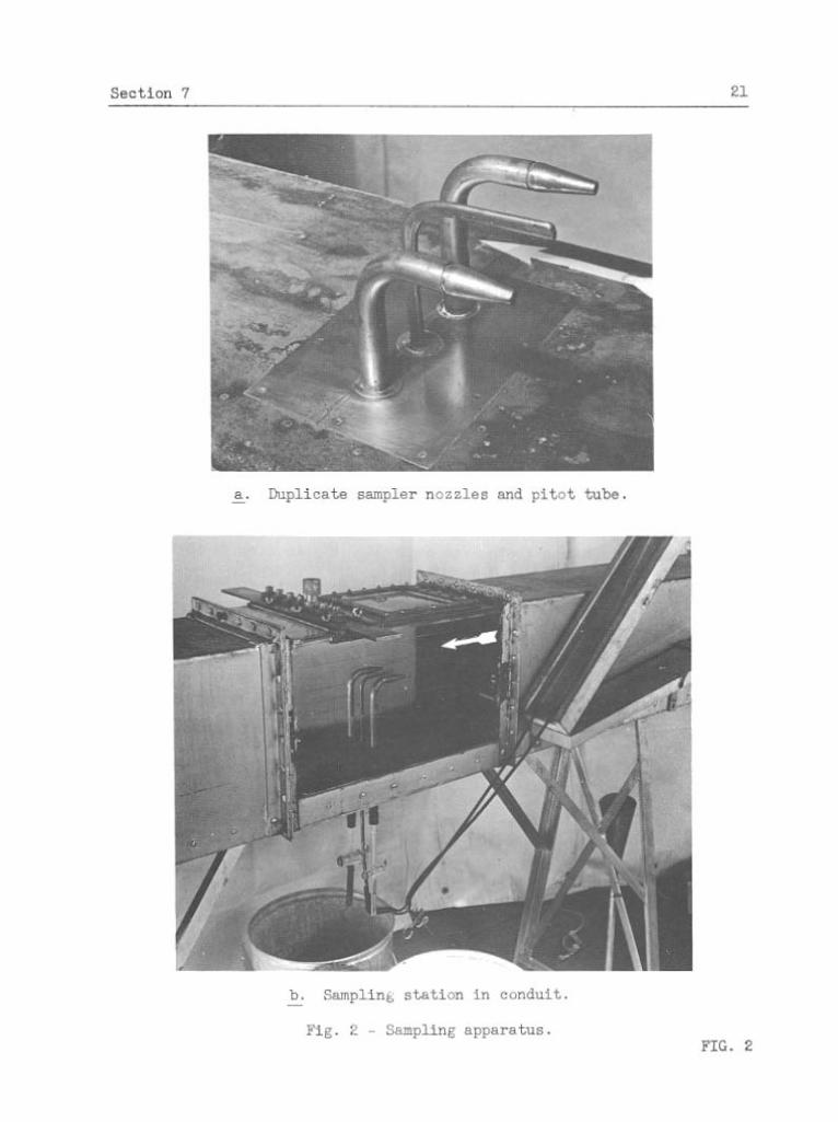
7. Samplina apparatus used i n study of s a m p l i n ~ action--Equipment
f o r c o l l e c t i n g samples o f t h e c i r c u l a t i n g suspension cons is ted p r i n c i p a l l y
o f t
a . An assortment of s a a p l e r nozzles which were designed a s r e a d i l y interchangeable t n s e r t s , t o s e a t with a t a p e r lock j o i n t i n t o t h e mouth of withdrawal tubes.
b. S p e c i a l l y shaped b r a s s tubes f o r withdrawing samples out 07 t h e c o n j u i t , which were equipped with s t o p cock va lves f o r c o n t r o l l i n g t h e sampling r a t e and provided with a tapered mouth a s a s e a t f o r t h e va r ious nozzle i n s e r t s .
c . Necessary p l a t e s and wa te r t igh t bushings i n s t a l l e d i n t h e t r anspa ren t sampling sec t ion of t h e conduit t o f a c i l i t a t e t h e i n s e r t i o n and adjustment of the sampling tubes and p i t o t tube t o any des i r ed poin t i n t h e sec t ion .
d. An a i r i n j e c t i o n pump f o r r e tu rn ing t h e water-sediment d ischarge of t h e samplers t o the head tank when i t was not re - ta ined a s a sample.
The t e s t i n g s e c t i o n of t h e conduit and the sampler nozzles and tubes f o r
withdrawing the samples a r e shown i n Fig. 2.
The nozzles a r e described i n d i v i d u a l l y and d e t a i l s and dimensions
a r e given i n t h e d i scuss ions of t h e r e spec t ive t e s t r e s u l t s . They were

20 Section 7
machined from heavy wall b rass tubing o r brass cyl inders t o the des i red
shapes and dimensions, and the c r i t i c a l dimenrlons were held t o within
0.001 i n . The back ends of the nozzles were machined on a standard t a p e r
of 4' included angle, t o s e a t and lock i n t o the s i m i l a r l y tapered mouth
of t h e sample withdrawing tubes. They seated f i rmly bu t could e a s i l y be
twisted ou t of t h i s j o i n t and interchanged.
The tubes f o r withdrawing the samples were of heavy wall brass tub-
ing i n two sizes: 9/16-in. and 3/8-in. ou t s ide diameter. The assortment
included those bent t o f a c e the nozzles d i r e c t l y i n t o t h e stream o r a t
s l i g h t angles t o t h i s d i rec t ion , t o f a c e the nozzles hor izonta l ly bu t
across t h e d i rec t ion of flow, and t o f a c e the nozzles v e r t i c a l l y .
The bushings i n s t a l l e d i n top and bottom of the t e s t i n g sec t ion were
designed t o accommodate e i t h e r of the two s i z e s of sampling tubes and t o
allow t h e i r adjustment v e r t i c a l l y i n t h e stream. A removable p la te 4 i n .
long and 6 i n . wide, inse r t ed i n the bottom of t h e conduit with i ts top
surface f l u s h with the bottom of t h e channel, contained three bushings,
spaced 1-1/2 i n . center t o center , which throughout most of the t e s t i n g
accommodatedthepitot tube and two sampling tubes arranged symmetrically.
A p l a t e i n the top of t h e sec t ion , designed t o s l i d e ac ross the con-
d u i t , contained bushings a t - - . cen te r s so t h a t a s many a s seven
could be used simultaneously. This f e a t u r e was not used i n the t e s t s ,
but was convenient i n the study of the sediment and ve loc i ty d i s t r i b u -
t i o n s throughout t h e sampling cross sec t ion , f o r which a sampling tube o r
the p i t o t tube was i n s t a l l e d and moved t o any des i red point over t h e
sect ion.
A r e a d i l y removable 8 by 8-in. p la t e was provided i n the top of the

22 Section 8
transparent section, jus t upstream from the s l id ing plate . It provided
easy access in to the conduit t o allow ins t a l l a t i on of sampler nozzles
o r other a l t e r a t ions of t e s t conditions.
The a i r in ject ion pump allowed continuous operation of the samplers
without a depletion of the suspension i n the system. Water and sediment,
withdrawn through the samplers, but not collectedassamples, was returned
t o the head tank.
8. Water and sediment used i n t e s t s of sampling action--Filtered
and chlorinated Iowa River water of the regular University of Iowa supply
was used throughout the t e s t s . During the program of tes t ing , thetemper-
a ture of the water varied from about 40° t o 80° F., but the temperature
of the suspension during t e s t s was controlled wjthin a range of from 650
t o 8S0 F., which range was found t o have no perceptible e f f ec t upon the
t e s t resu l t s . I n previous experiments it had been found t h a t the water
tended t o cause f loculat ion of f i ne grained sediments, but t h i s was no t
evident i n these t e a t s because of the large s izes of sediment and the
technique used. The waterwastreated with potassium dichromate, 0.02 per
cent concentration, t o i nh ib i t rust ing inside the pump and conduit. This
pract ice was found t o have no e f f ec t upon t e s t r e su l t s .
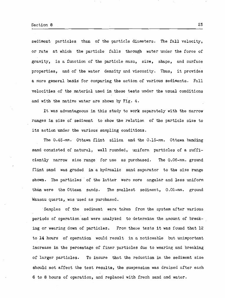
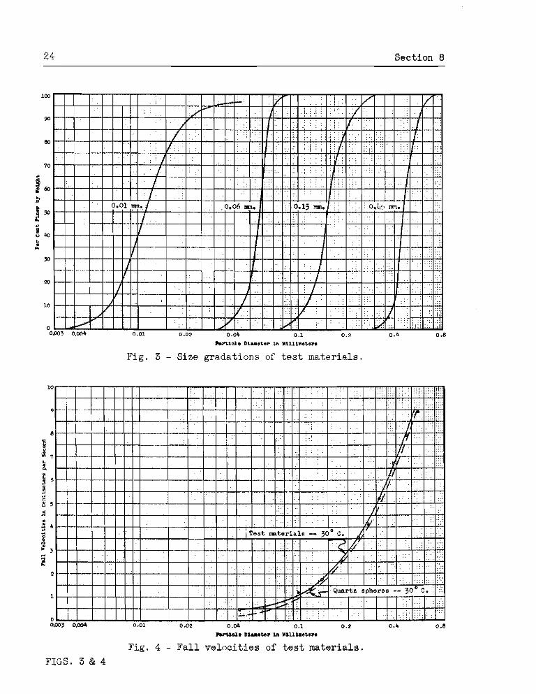
The sediment used consisted of four d i f fe ren t , r e a d i l y obtainable,
commercial sands, d i f fe r ing principally i n s i z e a s represented by the
s i ze analysis curves i n Fig. 3 . They are designated and referred t o by
the mean pa r t i c l e s i ze which on the s ize analysis curve is the pa r t i c l e
diameter corresponding t o the 50 per cent ordinate.
The behavior of suspended sediment under various sampler entrance
condition0 i s more d i r e c t l y a function of the f a l l velocity of the
Section 8 23
sediment p a r t i c l e s than of the p a r t i c l e diameters. The f a l l v e l o c i t y ,
o r r a t e a t which the p a r t i c l e f a l l s through water under the f o r c e of
g rav i ty , i s a function of the p a r t i c l e mass, s i z e , shape, and surface
p roper t i e s , and of the water dens i ty and v i scos i ty . Thus, it provides
a more general bas i s f o r comparing the ac t ion of various sediments. F a l l
v e l o c i t i e s of the mater ia l used i n these t e s t s under the usua l condit ions
and with the na t ive water a r e shown by F ig . 4 .
It was advantageous i n t h i s s tudy t o work separa te ly with the narrow
ranges i n s i z e of sediment t o show the r e l a t i o n of the p a r t i c l e s i z e t o
i t s ac t ion under the various sampling condit ions.
The 0.45-mm. Ottawa f l i n t s i l i c a and the 0.15-mm. Ottawa banding
sand consis ted of n a t u r a l , well rounded, uniform p a r t i c l e s of a s u f f i -
c i e n t l y narrow s i z e range f o r use a s purchased. The 0.06-mm. ground
f l i n t sand was graded i n a hydraulic sand separa tor t o the s i z e range
shown. The p a r t i c l e s of the l a t t e r were more angular and l e s s uniform
than were the Ottawa sands. The smallest sediment, 0.01-mm. ground
Wausau quar tz , was used a s purchased.
Samples of the sediment were taken from the system a f t e r various
per iods of operat ion and were analyzed t o determine the amount of break-
i n g o r wearing down of p a r t i c l e s . From these t e s t s it was found t h a t 12
t o 14 hours of operat ion would r e s u l t i n n noticeable but unimportant
increase i n the percentage of f i n e r p a r t i c l e s due t o wearing and breaking
of l a r g e r p a r t i c l e s . To insure t h a t the reduction in the sediment s i z e
should no t a f f e c t the t e s t r e s u l t s , the suspension was drained a f t e r each
6 t o 8 hours of operation, and replaced with f r e s h sand and water.
24 Sect ion 8
103
90
80
TO
5 .y 60 a
i = a u 40
L * Y)
20
I0
0 01103 O.M4 0.01 0.02 0.04 0.1 0.2 0.8
M l o l s D lus tar in ~ l l l t n e t e ~ .
Fig . 3 - Size gradat ions of t e s t ~ n a t e r i a l s .
Fig. 4 - F a l l v e l o c i t i e s of t e s t ma te r i a l s .
FIGS. 3 & 4
Section 9 25
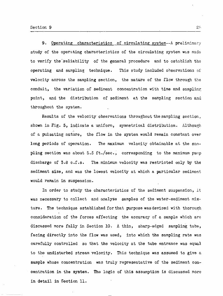
9. Operatina c h a r a c t e r i s t i c s of c i r c u l a t i n g system--4 preliminary
study of the opera t ing c h a r a c t e r i s t i c s of the c i r c u l a t i n g system was made
t o v e r i f y t h e ' r e l i a b i l i t y of the general procedure and t o e s t a b l i s h the
operat ing and sampling technique. This s tudy included ohsorvations of
ve loc i ty across the sampling sec t ion , the na ture of the flow through the
conduit , t he va r i a t ion of sediment concentrat ion with time and s n m p l i n ~
point , and the d i s t r i b u t i o n of sediment a t t h e sampling sec t ion and
throughout the system.
Resul ts of the ve loc i ty observations throughout thesampling sec t ion ,
shown i n Fig. 5, i nd ica te a uniform, symmetrical d i s t r i b u t i o n . Although
of a pu l sa t ing n&;re, the flow i n the system would remain constant over
long periods of operat ion. The maximum v e l o c i t y obtainable a t the sam-
p l ing sec t ion was about 6.5 f t . / s e c . , correspsnding t o the maximum punp
discharge of 3.8 c.f.s. The.minimum v e l o c i t y was r e s t r i c t e d only by the
sediment s i z e , and was the lowest ve loc i ty a t which a p a r t i c u l a r sediment
would remain i n suspension.
I n order t o study the c h a r a c t e r i s t i c s of the sediment suspension, it
was necessary t o c o l l e c t and analyze samples of the water-sediment mix-
t u r e . The technique es tabl i shed f o r t h a t purpose wasdevised with thorough
considera t ion of the fo rces a f f e c t i n g the accuracy of a sample which a r e
discussed more f u l l y i n Section 10. A t h i n , sharp-edged sampling tube,
f a c i n g d i r e c t l y i n t o the flow was used, i n t o which the sampling r a t e was
c a r e f u l l y con t ro l l ed so t h a t the ve loc i ty a t the tube entrance was equal
t o the undisturbed stream ve loc i ty . This technique was assumed t o give a
sample whose concentrat ion was t r u l y r ep resen ta t ive of the sediment con-
c e n t r a t i o n i n t h e system. The l o g i c of t h i s assumption is discussed more
i n d e t a i l i n Section 11.

26 Section 9
Inchos from c e n t e r c r o s s s e c t i o n of cvnd.iit -- v e i o c i t i o s shown i n ft./seo. -
Fie . 5 - Velocity contours s t samplinq s t a t i o n .
A study of the v a r i a t i o n with time of sediment concentrat ion a t a
sampling point was comtined with a comparat,ive study of the sediment con-
cen t ra t ion a t two sampling poin ts , sym~netr ica l ly loca ted i n a ho r i zon ta l
plane. Fwo samplers were i n s t a l l e d i n the sampling sec t ion with t h e i r
mouths a t a r b i t r a r i l y se lec ted po in t s indicated in Fig. 5, and a s e r i e s
of successive samples were co l l ec ted from each of the two po in t s simul-
taneously. The r e s u l t s of the s tudy a r e presented graphica l ly i n Fig. 6 .
The concentrat ion of the silccessive 20-sec. samples varied over a range
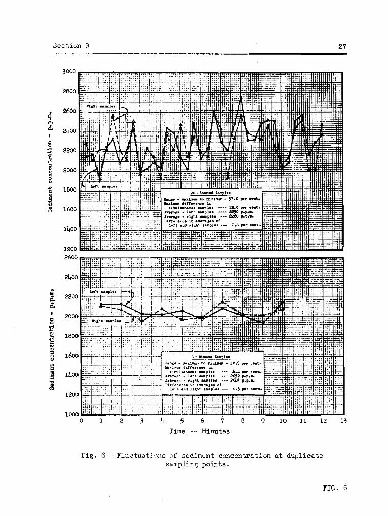
Fig . 6 - Fiuztua t i?ns c;f sediment concentrat ion a t dup l i ca te s snp l ing puin ts .

28 Sect ion 9
of 37 per cent of t h e mean concentrat ion, and the concentrat ion of t h e
successive 1-min. samples varied over a range of 10.5 per cent. These
f l u c t u a t i o n s in t h e concentrat ion were a t t r i b u t e d p a r t l y t o ordinary t u r -
bulence and p a r t l y t o t h e pulsa t ing na tu re of the flow. Their e f f e c t was
minimized by sampling over long periods of time, usua l ly about 10 min.
The s i m l t a n e o u s samples from t h e two sampling po in t s showed much
c l o s e r agreement than d id successive samples from the same point . The
maximum d i f fe rence i n concentration between two simultaneous 20-sec.
samples was 12 per cen t , and the average concentrat ions of the s e r i e s of
l e f t and r i g h t samples d i f f e r e d only 0.4 per cent . This es tabl i shed t h e
v a l i d i t y o f s i m u l t a n e o u s sampling, whereby t h e concentrat ion measured with
a s tandard sampler a t one of a p a i r of symmetrical sampling po in t s was
considered t o be t h e t r u e concentration a t t h e o t h e r t e s t sampler point.
To study the sediment d i s t r i b u t i o n a t the sampling sec t ion , a sam-
p l e r was placed a t t h e cen te r of the sampling sec t ion and samples of
10-min. dura t ion were co l l ec ted t o e s t a b l i s h the t r u e concentrat ion a t
t h a t point . Operating simultaneously with t h e f ixed sampler, another
was moved from point t o point v e r t i c a l l y and hor izon ta l ly throughout t h e
sec t ion , col lect inp: a sumple a t each point which was compared with t h e
corresponding sample a t t h e center . The sediment d i s t r i b u t i o n found f o r
d i f f e r e n t p a r t i c l e s i z e s i s shown in F ig . 7. The concentrat ion of sedi -
ment var ied over tlie depth of the conduit a s expected, t h a t i s , concen-
t r a t i o n s increased toward t h e bottom. I t var ied symmetrically across t,he
conduit, t h e maximum concentrat ion being a t t h e cen te r . Two sampling
points a t - t h e same depth and symmetrically located across t h e sec t ion had
t h e same averace concentrat ion of sediment, which v e r i f i e d the f ind ings
i n previous t e s t s .

50 Sect ion 9 -- .. . -- -
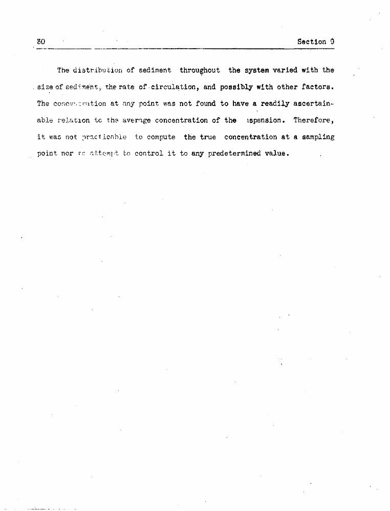
The d i s t r ibu t io r r of sediment throughout t h e system va r i ed with t h e
s i z e of sed.inent, the r a t e o f . c i r c u l a t i o n , and poeeibly with o t h e r f a c t o r s .
The co:icc7.c~- tion on a t :my po in t was n o t found t o have a r e a d i l y a s c e r t a i n -
ab le rel.::itlon tc 'he a v e n g e concent ra t ion of t h e lapension. Therefore,
it was not :~rnct.icnhi.e t o compute t h e t r u e concent ra t ion a t a sampling
poin t nor r c -tt.eml:t t o c o n t r o l it t o any predetermined value.
Sect ion 10 31
111. TESTS OF Sht4PLER ENTRI!NCE CONDITIONS
10. Flow o a t t e r n s a t the ontrance--Conditions a t t he mouth of a
sampler may be represented by t h e flo\,i pa t t e rn of the water-sediment
suspension approaching and entering t h r sampler. I t i s l o g i c a l t h a t any
curvature i n t h i s flow pa t t c rn , o r i n any of i t s stream l i n e s caused by
chnnges i n veloci ty of d i r e c t i o n , o r by disturbances due t o the sampler
i t s e l f , w i l l tend t o scgrc&ate the scdiment from t h e water. Th i s , i n
t u r n , will change the concentration of sediment in t h e f i lament e n t e r i n g
the sampler 'and, conccqucntly, a l s o i n the sample collected. This tend-
ency i s due t o the differonce i n dens i ty of the sediment and t h e viater;
t i c sediment, having grec.tcr dens i ty cnd i n c r t i r . than thc ~::.tcr, responds
l e s s r ap id ly than the vicitcr t o f o r c e s c l i cng in~ i t s not ion . The magnitude
of cny e r r o r i n t h e sediment contcnt of a sanplc r e s u l t i n g from t h i s
phenomenon would be a function of t h e . p a r t i c u l a r flow pa t t c rn e s t ab l i shed
and of the c h a r a c t e r i s t i c s of t h e scdincnt .
This phenomonon i o i l l ~ ~ s t r n t e d i n Fie;. 8 f o r three pnt-
Wrns of flow i n t o n snmpler whoso rnouth f a c e s cl i rcct ly i n t o the
stream. In Fig. Oh i s represented the cormon ccsc i n which t h e snmpling
r a t e i s slolv, and the vsl.ocit;- i ; ~ t h e aouth ;f t he s:m?lcr i s l e s s thnn
t h e nat i l ral strenm velocitj- some d i s t ancc upctrccn from the sampler. This
condi t ion i s p ic tu red bg- a filr.mcnt of the suspcnsion diverging i n cross
s e c t i o n a l a rea and decreasing i n ve loc i ty cs i t ~pproc~ches t h e mouth of
the sampler. The sediment from j u s t outside the bordcr of the sampled
f i l a m e n t , diverging l e s s rapid ly thc,n thc wctcr, c n t e r s the mouth of the
sampler ols an excess. In Fie;. 3s i s represented thc converse of t h i s
condi t ion i n vihich the veloci ty n t thc mouth of thc csmpler i s g rea te r

- stream l i n e s
-
a . Normal sampling r a t e -- i n t a k e veloci ty equal t o s t rean v e l o c i t y .
b. Sampling r a t e below normal -- a s i l l u s t r a t e d , r a t i o of in take veloci ty t o stream v e l o c i t y approximately 5/3.
c . Sampling r a t e above normal -- a s i l l u s t r a t e d , r a t i o o f in take ve loc i ty t o stream veloci ty approximatsly 3 .
Fig . 8 - Flow p a t t e r n s a t mouth of sampler i n t a k e . FIG. 8
tYan the natur-1 ctr.e?.m ve loc i ty . The sediment i n the sampled f i lament
tg?cds t o converge t , o e l e s s e r degree than the water, r e s u l t i n g i n a sample
too low i n sediment concentrat ion.
Conditions of s imi la r na ture mqv be prevalent with a l l types of
sam?le?s i i ~ d the corres;~onding flow p a t t e r n s m y be conveniently demon-
s t r a t e d by i n j e c t i n g streams of dye i n t o t h e suspension. A demonstration
of this nature nas been mnde recen t ly a t t h e Ca l i fo rn ia I n s t i t u t e of \
~ e c h n o l o g y ( ~ - J using severa l e x i s t i n g samplers.
?'lie t e s t s which follow a r e concerned d i r e c t l y wi th t h e q u a n t i t a t i v e
evaluat ion of er.rcrs i n snnples r e s u l t i n g from these phenomena.
11. Genera1 procedure i n testing_smalery.Jntakes--The genera l pro-
cedure follo~~:ij.!ci in t he +,f:,t.s t o c ~ n l u - t e t h e e f f e c t of sampler entrance
cor,dit,ionn ;nvolveti c r ~ l l e c t i n g t e s t samples under various in take condi-
t i o n s and comparirjg t h e i r sediment concentrat ions with the t r u e concen-
tr:lt.ion k ~ t , b:ie so.m>llng point,. As previously s t a t e d , t h e value of the t r u e
conc~c~,:ra?.ioa ' ; I ~ c necessar i ly so tabl ished by samgling, but t h i s was done
under c-:.ef':~Lly coxt ro l led " s t a n d a d sampling coriditions1I devised wi th
thorough con.:ids:'ation of the physical-forces ' a f f e c t i n g t h e accuracy of a
sam>le.,Thsse standard sam?ling condit ions were defined a s those i n whfc'z
t n e approaching f i lamezt of water-sediment suspension was no t de f l ec ted
o r d is turbed i n any manner u l l t i l it reached the mouth of t h e sampler.
The Standard sampling condit ions were a t t a i n e d by:
a. Using t h e standard sampling nozzle, shown i n Fig. 9, which was designed t o minimize i t s e f f e c t upon the approaching suspensior .
--------------- --------------------------------------------------------- ( 1 ) American Geophysical Union, Transactioqs 1940, P a r t I, p. 78, "The Use of Hydraulic Models i n the Design of >repended Load SamplersM by J . Pat OtNeiZ1.

34 -.-
Section 11
b. Facing the nozzle d i r e c t l y i n t o t h e flou: (normal posi- t i o n ) - - ~ ~ t h a t a sample would undergo no change of d i r e c t i o n i n ent,erinp the sampler.
c . Controlling the sampling r a t e so t h a t the v e l o c i t y i n the nGuth of t h e sampler would be equal t o t h e undisturbed ve- l o c i t y i n t h e stream a s i l l u s t r a t e d i n F i g . 85, ara no change i n ve loc i ty o r d i rec t ion would r e s u l t a s t h e sample ..as co l l ec ted .
With t h i s minimum of disturbance and change of flow of the sample 8s it
approached 8nd entered t h e sampler, no fo rces were v isual ized which might
tend t o a f f e c t :.he accuracy.
L-. Jz !. ".-- + I I , , 4 I- - B
Sect ' onaj. .-.:I,< s i d e view End view
Flg. 9 - Stqniara nozzle in take diameter 0.25 i n .
Fur ther . from the study of the sediment suspension c h a r a c t e r i s t i c s
a t the samp.Ling sec t ion . Section 3, it we3 es tabl i shed t h a t :
a . Samples co i l ec ted over long periods of time, 5 t o 10 - min., provided a s a t i s f a c t o r y average of the f l u c t u a t i n g con- cen t ra t ion .
b. Values of sediment concentrat ion, based on long sam- - p l e s , a r e the seme a t two sampling po in t s symmetrically located i n a hor izonta l plane.
Based on these f : ~ ? : i h ~ e n t a l assumptions and c h a r a c t e r i s t i c s , the pro-
cedure involved c o l l e c t i n g , from twin sampling points , a t e s t a n d a stand-
ard sample simult,sneor;:;lj over a 10-min. sampling period. Any d i f f e r e n c e

Sect ion 12
between the sediment concentration of the t e s t sample and t h n t of the
s tandard sample was a t t r i b u t e d a s an e r r o r due t o the p a r t i c u l a r sampling
condi t ions i n the t e s t sam?ler.
12. Outline of tests--All sampling condit ions were arranged and
c l a s s i f i e d according to t h e i r devia t ion from the assumed standard sampling
condi t ions i n the following manner:
a . Deviations from the normal sampling r a t e . -
b. Deviation from the normal pos i t ionof thesnmpler nozzle. - c. Deviations i n s i z e and shape of the nozzle. -
d . Disturbance of samale by nozzle appurtenances. - e. Major va r i a t ions from standard condi t ions i n the
o r i en tn t ion of sampler nozzle.
These devia t ions a r e l i k e l y t o occur i n various combinations and
t h e i r e f f e c t should vary wi th sediment s i z e and stream veloc i ty . Tes ts
were conducted i n an order arranged t o evaluate t h e i r e f f e c t s sepa ra te ly
and i n probable combinations.
kach t e s t consisted of a s e r i e s of samples co l l ec ted a t i n t ake r a t e s
from about 25 per cent t o about 300 per cent of normal, with a s i n g l e
s i z e o f sediment, a s i n g l e stream ve loc i ty , and one nozzle placed i n one
pos i t ion . Thus each t e s t showed the e f f e c t of dev ia t ions from normal
in take r a t e s e i t h e r alone, o r i n combination wi th any o the r des i r ed de-
v i a t i o n from standard condit ions.
13. Techniaue i n c o l l e c t i n g and a n a l y z i n ~ samales--The technique
followed i n co l l ec t ing and analyzing the samples allowed an i m e d i a t e
determination of t h e i r sadlment concentrat ions, and re su l t ed i n a high
degree of accuracy.
36 Section 1 3
The sampling period of 10 min., es tabl i shed i n the study of f luc tua-
t i o n s of' sediment concentration a t the twin sampling points , Sect ion 9,
r e su l t ed i n l a rge volumes of water and sediment i n each sample. The
samples, usual ly i n volumes from 5 t o 50 gal lons were weighed d i r e c t l y .
The sedimentwas separated from the water e i t h e r b y s ieves o r sedimentation
and was weighed d i r e c t l y i n the wet condition by a water displacement
method. This method consisted i n determining the d i f fe rence i n weight of
a given volume of water and an equal volumeofthe water-sediment mixture.
Equal volumes were obtained by measurement i n volumetric f l a s k s . This
d i f f e rence , the buoyed up weight of sediment, mult ipl ied by the s p e c i f i c
gravi ty of sediment and divided by the d i f ference i n s p e c i f i c g rav i ty of
sediment and t h a t of water gave the t rue weight of dry sediment. The
r a t i o of the dry weight of sediment t o the weight of water gave the sedi-
ment concentration of t h e sample which could be expressed i n per cent
o r i n p a r t s of sediment per mi l l ion p a r t s of water-sediment, p.p.m.
In preliminary s t u d i e s of the sediment suspension c h a r a c t e r i s t i c s ,
where smaller samples were col lec ted , these were analyzed separa te ly by
siphoning off the water and drying the sediment. This method was used
a l s o t o ve r i fy t h e accuracy of the displacement method of determining the
quant i ty of sediment i n the samples.
The mean sampling r a t e f o r each sample was computed from the t o t a l
volume of the sample and the time of sampling. The ve loc i ty a t t h e mouth
of t h e nozzle was determined by d iv id ing the sampling r a t e by the a rea
of the nozzle mouth, and was usually expressed a s a r a t i o t o t h e normal
o r undisturbed stream veloci ty . The "normal" sampling r a t e was that re-
s u l t i n g i n a ve loc i ty a t the mouth of the nozzle, in t ake veloci ty , equal

Section 14 37
to the normal or stream velocity. The area of the nozzle mouth was that
defined by the sharp edge.
14. Errors in sediment concentration of samples collected with
standard sampler nozzle--Tests were made to evaluate the effect of devi-
ations from the normal sampling rate upon the samples collected, and to
show the importance of controlling the sampling rate into a sampler. A
series of samples collected at rates varying from about 1/4-normal to
about 3-normal, with a single size sediment and a singls stream velocity,
comprised one test. The standard nozzle, shown in Fig. 9, was used,
oriented in the normal position so that any effect upon the flow pattern
of the sampled filament and consequently any error in the sediment con-
centration of the sample could be attributed to the particular deviation
of the intake rate from normal alone.
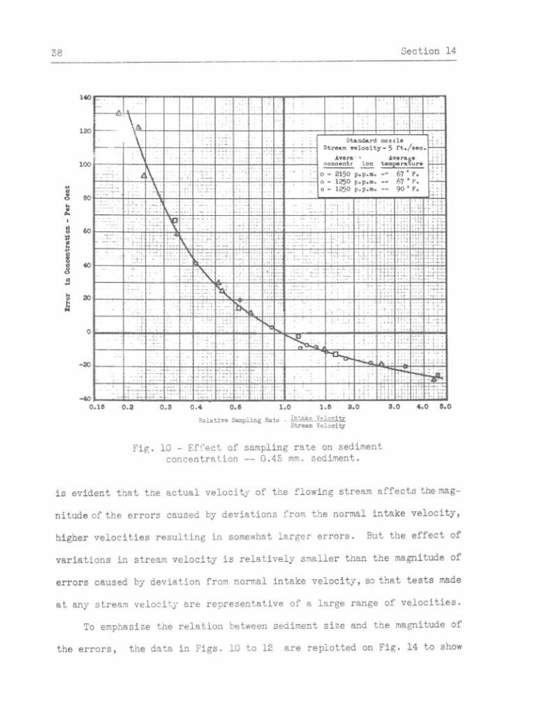
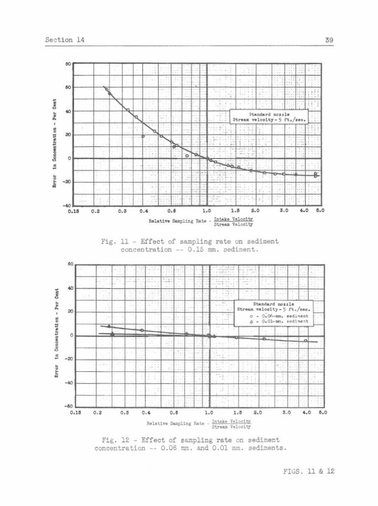
Results of four tests with a stream velocity of 5 ft./sec., and
suspensions of 0.45-mm., 0.15-mm., 0.06-m., and 0.01-mm. sands are shown
on Figs. 10 to 12. These data show that appreciable errors in the sedi-
ment concentration of" a sample result from an incorrect or uncontrolled
sampling rate. Samples collected at rates such that the velocity in the
mouth of a nozzle is less than the normal stream velocity contain an
excess of sediment, while samples collected at rates above normal are low
in sediment content. Errors resulting from sampling rates below normal
are considerably larger in magnitude than errors resulting from compar-
able deviations in sampling rate above normal. The errors increase in
magnitude as the samgling rate increases above normal.
Resultsofthree tests using 0.15-mm. sediment with stream velocities
of 3, 4, and 5 ft./sec. are shown together on Fig. 13. From these data it


Section 15 41
the e r r o r i n concentrat ion of samples a s a function of t h e s i z e of sedi-
ment f o r s e v e r a l sampling r a t e s . ' A s t h e s i z e of sediment increased above
0.06-mm., the magnitude of the e r r o r ~ i n sediment concentrat ion of the
samples increased rap id ly . h'ithin t h e range of Stokes1 Law, sediment
s i z e s below 0.06-mm., the e r r o r s were comparatively small i n magnitude
and var ied l e s s r ap id ly with t h e sediment s i z e .
Moderate v a r i a t i o n s i n t h e a c t u a l sediment concentrat ion and i n the
temperature of the suspension were found t o have no pe rcep t ib le e f f e c t
upon the r e e u l t s . Data from two s e r i e s of samples whose mean concentra-
t i o n s s e r e 1250 and 2150 p.p.m. and two s e r i e s of samples co l l ec ted a t
t e m ~ e r a t u r e c of 67' and 90' F., a r e presented i n Fig. 10. There i s no
cons i s t en t va r i a t ion i n these data which can be a t t r i b u t e d t o v a r i a t i o n s
i n t h e temperature o r the sediment concentrat ion.
15. E f f e c t of small devia t ions from normal nozzle o r i e n t a t i o n on
e r r o r s i n sediment concentration--The d i r e c t i o n of o r i e n t a t i o n of a sam-
p l e r nozzle with r e spec t t o the d i r e c t i o n of the stream cur ren t might
vary considerably during sampling. Any devia t ion of a sam?ler nozzle
from fac ing d i r e c t l y i n t o the stream flow represents a devia t ion from
t h e spec i f i ed standard sampling condi t ions . To evaluate the e f f e c t s of
small devia t ions , t e s t s were made with the standard nozzle s e t a t angles
of lo0, 20°, and 30' from the normal pos i t ion . Each t e s t cons is ted of a
s e r i e s ofsamples co l l ec ted a t various in take r a t e s , and showed the e f f e c t
of dev ia t ions from normal pos i t ion a s well a s of devia t ions from normal
in take r a t e . Results of these t e s t s a r e shown i n Fig. 15 and t h e corres-
ponding t e s t with the standard nozzle i n t h e normal pos i t ion has been re-
p l o t t e d thereon f o r comTarison. The r e s u l t s of the 10' t e s t have been


Section 17
the sediment concentration of a sample resul t ing from deviations from the
normal sampling r a t e , are somewhat la rger with smaller nozzles, but a t
the norm...:- sampling ra te , the samples collected through nozzles of
d i f f e r en t s izes were iden t ica l i n concentration.
These r e su l t s from the collection of samples iden t ica l i n sediment
concentration w i t h nozzles of d i f f e r en t mouth areas s e r w t o ver i fy the
accuracy of the standard sampling conditions.
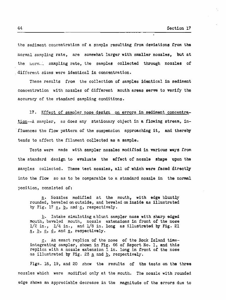
17. Effect of sampler nose design on e r ro r s i n sediment concentra-
---A sampler, as does any s ta t ionaly object i n a flowing stream, in-
fluences the flow pattern of the suspension approaching i t , and thereby
tends to a f f ec t the filnment collected a s a sample.
Tests were made with sam?ler nozzles modified i n various ways from
the standard design t o evaluate the e f fec t of nozzle shape upon the
samples collected. These t e s t nozzles, a l l of which were faced d i r e c t l y
i n to the flow so a s t o be comparable t o a standard nozzle i n the normal
~ o s i t i o n , consisted of:
a . Nozzles modified a t the mouth, with edge bluntly rounded, beveled on outside, and beveled on inside a s i l l u s t r a t e d by Fig. 17 2, b, and.^, respectively.
b. Intake simulating ab lunt sampler nose with sharp edged mouth, beveled mouth, nozzle extensions i n f ron t of the nose 1/2 i n . , 1/4 in . , and 1/8 in . long a s i l l u s t r a t e d by Fig. 21 a, b, c, c l , and g, respectively.
c. An exact repl ica of the nose of the Rock Island time- integrat ing sampler, shown i n Fig. 66 of Report No. 1, and t h i s repl ica with a nozzle extension 1 in . long i n f ron t of the nose a s i l l u s t r a t e d by Fig. 23 2 and 1, respectively.
Figs. 18, 19, and 20 show the r e su l t s of the t e s t s on the three
nozzles which were modified only a t the mouth. The nozzle with rounded
edge shows an appreciable decrease i n the magnitude of the e r rors due t o


50 Sect ion 17
The b lunt nose in take wi th sharp edged mouth and without nozzle
extensions co l l ec ted 12 per cen t excess of sediment a t the normal in take
r a t e . A t lower sampling r a t e s , it approached the a c t i o n of the s tandard
nozzle. The a c t i o n of t h e blunt nose in take was improved s l i g h t l y by
bsvel ing the edge of the mouth i n which case only 6 per cen t excess of
sediment was co l l ec ted a t t he normal in t ake r a t e , A t low i n t a k e r a t e s t h i s
nozzle co l l ec ted samples s l i g h t l y l e s s i n e r r o r than d id the s tandard,
but the d i f f e rence i s unimportant i n com?arison t o the e r r o r caused by
the slow r a t e .
Nozzle extensions of 1/2 and 1/4 i n . i n f r o n t of the nose gave re-
s u l t s which were the same a s those obtained wi th a s tandard nozzle.
Resul t s of these t e s t s were not p lo t t ed because they were s o nea r ly the
same a s those of t h e s tandard nozzle. The 1/8-in. nozzle extension was
not s u f f i c i s n t t o obvia te t h e e f f e c t of the b lunt nose, but it changed
i t s a c t i o n so t h a t , a t the normal r a t e , i n s t ead of c o l l e c t i n g an excess
of sediment the nozzle co l l ec ted i n s u f f i c i e n t sediment.
The a c t u a l lengths of these extensions a r e meaningless un les s com-
pared dimensionally with the s i z e of the mouth, and the s i z e and shape of
the nose. A s s u f f i c i e n t da ta were n o t co l l ec ted t o al low a r e l i a b l e
dimensionless c o r r e l a t i o n of these f a c t o r s , conclusions a s t o t h e e f f e c t i v e
l sng th of nozzle extensions must be avoided.
F ig . 24 shows the r e s u l t s of t e s t s with the r e p l i c a of the nose of
t h e Rock Is land sampler, wi th and without an extension of the nozzle
a s i l l u s t r a t e d i n Fig. 23. The d a t a show t h a t a sampler of t h i s type
c o l l e c t s a considerable excess of sediment, even a t a normal sampling
r a t e . With t h e nozzle extended 1.0 i n . i n f r o n t of t h e nose of the


Section 18 53
18. Effect of f l a p valves a t sampler intnites--Flap valves, commonly
placed above the mouths of instantaneous, horizontal t r a p s a m ~ l e r s , un-
doubtedly cause disturbances i n the water-sediment filament approaching
the mouth of the sampler. To evaluate the general magnitude of the e f fec t
of such conditions upon the regular operation of a sampler, t e s t s were
made with models of f l a p valves i n the open posit ion attached t o the
standard nozzle and protruding over and i n f ron t of the mouth of the
nozzle. Although these t e s t s did not duplicate the operation of instan-
taneous samplers, the r e su l t s a r e believed t o be representative of re-
s u l t s obtained with such sam?lers, inasmuch a s the phenomenon involved i s
fundamentally the same.
Flap valves, a s i l l u s t r a t e d by Fig. 25, were tes ted i n each of three
posit ions, namely:
a_. Valve extended horizontally from top of nozzle mouth.
b. Valve deflected upward from the top o f the nozzle mouth a t a n a n g l e of 30' with the horizcntal .
c. Valve deflected downward from the top of the nozzle a t an ahgle of 30° with the horizontal.
Each t e s t consisted of a s e r i e s of samples collected a t d i f fe ren t sam-
pl ing ra tes .
Results of these t e s t s a r e shown i n Fig. 26. The curve from the
basic standard sampler i n the normal position without f l a p valves is re-
peated fo r comparison. These data show tha t the f l a p valve i n the hori-
zontal position had re la t ive ly l i t t l e e f fec t on the accuracyofthe samples
co1leci;e;i through a s~andard nozzle. The f l a p valve inclined upward
tended to de f l ec t an excess of sediment i n t o the nozzle, and the f l a p
valve inc1.ined downward, obstructing the flow d i r ec t ly i n to the nozzle,

Sec t ion 1 9 55
had t h e opposi te e f f e c t . Although t h e e f f e c t s of these appurtenances
were small i n comparison t o t h e magnitude of t h e e r r o r s which r e s u l t from
an i n c o r r e c t sampling r a t e , they should be avoided i f poss ib le where
h ighly accura te sampling is des i r ed .
19. E r ro r s i n sediment concent ra t ion of sam3les co l l ec ted wi th
g q z z l e s i n v e r t i c a l uosition--Several nozzles were o r i en ted i n t h e t e s t
condui t to simulate sampler entrance condi t ions i n t h e common slow f i l l i n g
o r b o t t l e type samplers and t o some ex ten t i n v e r t i c a l t r a p samplers. For
photographs and d e s c r i p t i o n s of these samplers, re ference is made t o
Report No. 1 of t h e s tudy of "Nethods Used i n Measurement and Analysis of
Sediment Loads i n Streams," Sect ions 47 t o 53 f o r v e r t i c a l t r a p samplers
and Sec t ions 63 t o 81, 89 and 90, f o r t h e slow f i l l i n g samplers. Samplers
of these types have mouths which do n o t f ace i n t o t h e stream flow and a
sample e n t e r i n g them must undergo a 90' change of d i r e c t i o n , and con-
sequent ly t h e r e i s a tendency f o r segregat ion and l o s s of sediment t o
t a k e p lace .
Severa l of t h e samplers r e fe r red t o a r e constructed wi th sepa ra te
a i r exhausts so that t h e inflow of t h e sample is s teady and continuous.
I n those n o t so equipped t h e flow p a t t e r n of an e n t e r i n g sample i s d i s -
turbed by the spasmodic escape of a i r . Such d i s tu rbance , o r bubbling
Ciction, and i ts e f f e c t upon t h e sampled f i l amen t , was neglected i n these
t e s t s . The var ious nozzles or iented i n t h e v e r t i c a l p o s i t i o n were t e s t e d
wi th t h e same procedure as described i n Sect ion 11, each t e s t c o n s i s t i n g
of a s e r i e s o f s a m p l e s c o l l e c t e d a t d i f f e r e n t sampling r a t e s . The sampling
r a t e s were expressed, as i n t h e t e s t s wi th nozzles f ac ing i n t o t h e stream,
56 Section 19
by the r a t i o of the ve loc i ty i n the mouth, in take veloci ty , t o the stream
ve loc i ty . Although the physical s ign i f icance of such a r a t i o i s not
c l e a r l y defined f o r these conditions, i t i s a convenient f a c t o r t o use i n
' present ing the r e s u l t s . The entrance conditions a s es tabl ished by the
var iab le f a c t o r s of stream ve loc i ty , sediment s i z e , and physical f ea tu re s
of the sampler such a s s i z e , shape, and s i z e of mouth, were varied f o r
the d i f f e r e n t t e s t s t o allow evaluation of the e f f e c t of each f a c t o r
separately.
The nozzles consisted of the following:
a . Standard shaped nozzles, i n each of two mouth s i zes , placed i n the v e r t i c a l posi t ion a s i l l u s t r a t e d by Fig. 27.
b. Intakes consis t ing of o r i f i c e s , 0.150 and 0.250 i n . i n diameter, i n the top surface of a t h i n horizontal p l a t e a s i l l u s t r a t e d by Fig. 31.
c. Intake consis t ing of an o r i f i c e , 0.250 i n . i n diameter i n t h e top surface of a mushroom d i sk a s i l l u s t r a t e d by Fig. 35.
These nozzles were designed t o approximately simulate the entrance
conditions of ac tua l samplers and a r e not exact r ep l i cas of any one
sampler.
Tests with the standard nozzles i n the v e r t i c a l pos i t ion were made
a s follows:
a . Four t e s t s , using 0.45-nun., 0.15-nun., 0.06-mm., and 0.01-k. sediment, respect ively, with 0.25-in. nozzle and stream ve loc i ty of 5 f t ./sec.
b. One t e s t , using 0.15-mm. sediment, with 0.25-in. nozzle and 3-ft ./sec. stream ve loc i ty for comparison with similar t e s t , above, a t 5 f t . / sec . stream veloci ty t o show the e f f e c t of t h i s f ac to r .
c . One t e s t , using 0.45-mm. sediment, with 0.15in. nozzle and 5-ft ./sec . stream ve loc i ty for comparison with s imi l a r t e s t , above, wi th 0.25-in. nozzle t o show the e f f e c t of nozzle s i z e .
Resul ts of the f o u r t e s t s w i t h v a r i o u s s i z e s of sediment a r e presented
i n Fig. 28. Large e r r o r s i n t h e sediment content of a sample r e s u l t e d
from t h e abrupt change i n d i r e c t i o n of flow a t the mouth of t h i s sampler.
The e r r o r s , a l l negat ive, demonstrate t h a t t h e sediment was segregated
from the sampled f i lament of water a s it turned t o e n t e r t h e sampler.
The sediment p a r t i c l e s passed on and d i d no t e n t e r the mouth of the sam-
p l e r . The f a c t o r which a f f e c t e d the magnitude of the e r r o r most was the
sediment s i z e s a s shown by t h e four curves i n Fig. 20. A t any sampling
r a t e , t h e e r r o r increased with sediment s i z e up t o the 0.15-mm. sediment
but t h e r e was l i t t l e d i f f e rence i n the r e s u l t s obtained wi th t h e 0.15-mm.
and 0.45-mm. sediments. The e r r o r varied g r e a t l y wi th the sampling r a t e ;
from a very high value a t low r a t e s t o a smaller and nea r ly constant
value a t normal and f a s t e r r a t e s . With t h e smaller s i z e s of sediment,
t h e e r r o r var ied l e s s markedly wi th the sampling r a t e but was s t i l l nega-
t i v e and of apprec iable magnitude.
Resul t s of two comparable t e s t s , d i f f e r i n g only i n stream ve loc i ty
a r e presented i n Fig . 29 t o show t h e e f f e c t cf t h i s f a c t o r upon t h e
magnitude of t h e e r r o r s . The e r r o r was l a r g e r wi th the f a s t e r stream
ve loc i ty , bu t the e f f e c t of stream v e l o c i t y was small i n comparison t o
t h e magnitude o f t h e t o t a l e r r o r caused by t h e o r i e n t a t i o n of t h e sampler.
Resul t s of two comparable t e s t s wi th d i f f e r e n t s i z e s of sampler
mouths but with a l l o the r condit ions the same a r e shown i n Fig. 30. The
magnitude of the e r r o r var ied inve r se ly , and t o an apprec iable ex ten t ,
with the s i z e of opening, l a r g e r e r r o r s r e w l t i n g w i t h t he smal ler nozzle.
Testa wi th in t akes cons i s t ing of an o r i f i c e i n a f l a t ho r i zon ta l
p l a t e , shown i n Fig . 31, were made a s follows:

Section 19
a . Three t e s t s , using 0.45-mm., 0.15-mm., and 0.06-mm. sediment, wi th intake 0.250-in. diameter and stream ve loc i ty of S f t . / sec .
b. Two t e s t s , with stream v e l o c i t i e s of 4 f t . /sec. and 3 f t Jsec., wi th in take 0.250-in. diameter and 0.15-mm. sediment f o r comparison with s i m i l a r t e s t above a t 5 f t . / sec . t o show . the e f f e c t of stream ve loc i ty .
c . One t e s t wi th in take 0.150-in. diameter and with 0.15-&. sediment and 5 f t ./sec. stream ve loc i ty f o r comparison wi th the s i m i l a r t e s t above with in take 0.25-in. diameter t o show the e f f e c t of mouth s i z e .
Results of the th ree t e s t s with d i f f e r e n t s i z e s of sediment a r e
shown i n Fig. 32. A s i n the t e s t s on the standard nozzle i n t h e v e r t i c a l
pos i t ion , the e r r o r i n sediment content of a sample was negative, demon-
s t r a t i n g the l o s s of sediment from the sampled f i lament a s it turned t o
en te r the mouth of the sampler. The magnititde of the e r r o r , a s i n a l l
previous t e s t s , decreased with smaller s i z e s of sediment, b u t t h i s t e n d -
ency was l e s s evident wi th the two large s i z e s of sediment, 0.15 mm. and
0.45 mm., respect ively . For the p a r t i c u l a r condit ions of these t h r e e
t e s t s , the sampling r a t e had l i t t l e e f f e c t upon th* magnitude of e r r o r .
The three t e s t s a t d i f f e r e n t stream v e i o c i t l e s ?resented i n Fig. 33, in-
d ica ted t h a t a s the stream veloci ty decroased the proportion of sediment
enter ing the sampler increased, r e s u l t i n g i n an excess of sediment being
col lec ted when the stream ve loc i ty and r e l a t i v e sampling r a t e were low.
The two t e s t s i n which s i z e was the va r iab le , presented i n Fig. 34,
indicated t h a t both the magnitude of e r r o r and the r e l a t i v e e f f e c t of the
sampling r a t e on the e r r o r i n sample concentration, were dependent on the
mouth s i z e .
From these t e s t s with f l a t p l a t e nozzles, it was concluded t h a t the
entrance condit ions and; t h e i r e f f e c t upon a sample a r e too complex f o r

Section 20
thorough a n a l y s i s without more exhaustive t e s t s . It can be reasoned that
the re a r e two genera l phenomena a f f e c t i n g t h e r e l a t i v e behavior of the
sediment and water passing and en te r ing a sampler of t h i s type. The one
a l ready discussed i s t h a t t h e sediment, being of g r e a t e r d e n s i t y than t h e
water, tends b y i t s g r e a t e r i n e r t i a t o ~ a s i s t t h e sharp d i r e c t i o n a l change.
and passes by t h e sampler mouth. The second a r i s e s from t h e e f f e c t of
the f l a t p l a t e upon t h e flow c h a r a c t e r i s t i c s . In t h e suspension adjacent
t o the p l a t e , boundary condit ions a r e s e t up which a r e similar t o those
along t h e boundaries of a conduit. Turbulence i s decreased i n this l a y e r ,
r e s u l t i n g i n the s e t t l i n g out of sediment along the su r face of t h e p l a t e
and tho movement of t h e sediment i n higher than normal concentrat ions
u n t i l it drops i n t o t h e mouth of t h e sampler a s excess sediment. These
two phenomena a r e opposi te i n na ture and e f f e c t ; the former predominating
a t higher stream v e l o c i t i e s , and t h e l a t t e r a t lower v e l o c i t i e s . A con-
d i t i o n may be considered, with a suspension of sediment varying widely i n
p a r t i c l e s i z e s , i n which samples would contain i n s u f f i c i e n t q u a n t i t i e s of
smal l s i z e s of the sediment and an excess of t h e l a r g e s i z e s .
Resul ts of t h e s i n g l e t e s t wi th t h e mushroom shaped sampler in take ,
shown i n Fig. 36, i n d i c a t e that i t s ac t ion was s i m i l a r t o that of t h e
o t h e r v e r t i c a l in t akes . Exnaaustive t e s t s were n o t made wi th t h i s nozzle,
a s t h e r e was no ind ica t ion of advantages t o be gained i n a sampler de-
signed along these l i n e s . It seemed probable t h a t a thorough a n a l y s i s
of t h e in take condit ions i n t o t h i s nozzle would be complicated by t h e
same va r i ab le f a c t o r s and phenomena a f f e c t i n g the f l a t p l a t e nozzle.
20. Er ro r s i n sediment concentrat ion of samples co l l ec ted through
sampler in take hor izonta l and normal t o f low--I t was pointed out i n


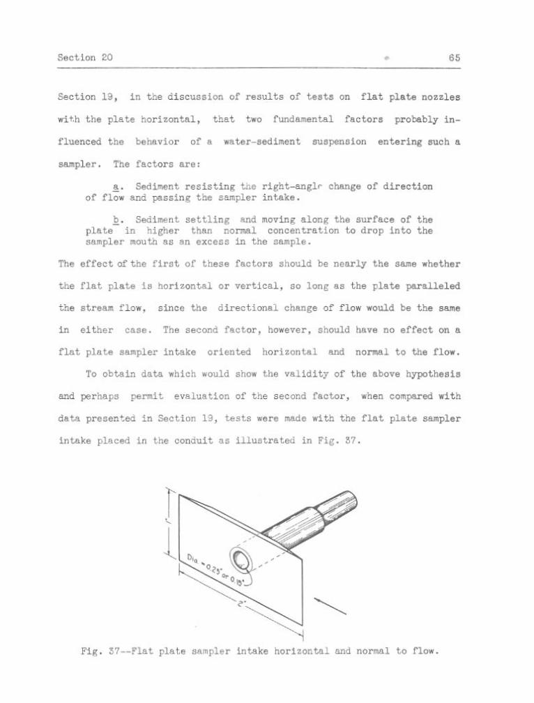
Sect ion 20
Tes ts of t h e f l a t p l a t e sampler i n t ake hor izonta l and normal t o flow
were made a s follows:
a . Two t e s t s , us ing 0.45-m. and 0.15-mm. sediment, wi th t h e 0-15-in. mouth and stream ve loc i ty of 5 f t . / s e c .
b. Two t e s t s with sediment and stream ve loc i ty condi t ions same a s above but with t h e 0.25-in. mouth.
c. One a d d i t i o n a l t e s t with a stream ve loc i ty of 3 f t . / see . , 0.15-hi. sediment, and t h e 0.15-in. mouth.
Resul ts of t h e four t e s t s described i n and 1 a r e shown i n Fig. 38.
The negat ive e r r o r was l a r g e i n magnitude and was d e f i n i t e l y a funct ion
of t h e sediment s i z e . It var ied t o some ex ten t w i th t h e sampling r a t e ,
i nc reas ing wi th decreasing in take v e l o c i t i e s . The magnitude of t h e e r r o r
was not a f f ec t ed ma te r i a l ly by the Cifference i n mouth s i z e .
Resul t s of t h e two t e s t s a t 5 end 3 f t . / s ec . stream ve loc i ty , o the r
f a c t o r s t h e same, a r e shown i n Fig. 59. The e f f e c t of the stream v e l o c i t y
upon t h e magnitude o f t h e e r r o r was p r a c t i c a l l y neg l ig ib l e and n o t c l e a r l y
def ined by the d a t a .
A comparison of t h e curves ir. Figs. 38 nnci 39 wi th s i m i l a r curves i n
F igs . 32 and 53, respec t ive ly , i l l o a t r a r e s t h e r e l a t i v e a f f e c t s of t h e
two i n t a k e phenomena discussed above. The negat ive e r r o r s discusded i n
t h i s s e c t i ~ n were a l l g r e a t e r i n magnitude f o r a given s e t of t e s t con-
d i t i o n s than were t h e e r r o r s discussed i n Sect ion 19. This f a c t v e r i f i e s
t h e a n a l y s i s presented a t t h e beginning of t h i s s ec t ion , s ince , a s was
noted i n Sect ion 19 , t h e two f a c t o r s thought t o a f f e c t sample concentra-.
t i o n , f l a t p l a t e i n t a k e s or ien ted v e r t i c a l l y , tend t o o f f s e t eacn o ther .


I V . DEPOSITION OF SEDIMENT IN INSTANTANEOUS HORIZONTAL SAMPLERS
2i. Scope of depos i t ion studp--The usual form of an instantaneous
sampler c o n s i s t s of a hor i zon ta l cyl inder with a mechanism a t each end
dezigned f o r i n s t a n t closing. The sampler is usua l ly suspended a t any
d e s i r e d poin t i n a stream by means of a cable. The cyl inder i s maintained
i n a ho r i zon ta l pos i t ion p a r a l l e l t o the stream flow by means of a vane
and f i n s fas tened t o the sampler i n a manner which w i l l n o t obstruct,
stream flow. Water flows f r e e l y through the cyl inder u n t i l t h e operat ion
k i p s t,he ins tant -c los ing mechanism thereby ent rapping a sample. Under
c e r t a i n condit ions it has been observed t h a t samples which conta in an ex-
cess of sediment were co l l ec ted i n such types of samplers. I n o r d e r t o
i n v e s t i g a t e t h i s phenomenon a s e r i e s of experiments were ca r r i ed o u t i n
t h e r e c i r c u l a t i n g apparatus described i n Sect ion 5 of t h i s r e p o r t . The
scope of the s tudy was very l imi t ed , but i n order t o make t h e record of
t h e experimental work complete, t h e following desc r ip t ion o f t h e t e s t s and
s ta tement of r e s u l t s i s presented.
This excessive depos i t ion of sedimen.t probably l a r g e l y r e s u l t s from
a reduct ion of t h e v e r t i c a l v e l o c i t y components i n t h e f i lament e n t e r i n g
t h e sampler. Generally, flowing water possesses t u r b u l e n c e ~ t h momentary
eddies which have upward ve loc i ty components of s u f f i c i e n t magnitude t o
e l e v a t e sediment par t , ic les i n the stream. When t h e f i lament e n t e r s t h e
mouth of the sampler the v e r t i c a l components a r e r educedby the boundaries
of the hor i zon ta l tube; the re fo re , some of the l a r g e r p a r t i c l e s i n s u s p e n -
s ion s e t t l e t o t h e bottom of t h e sampler. The reduction of v e l o c i t y due
t o t h e f r i c t i o n on t h e i n s i d e of t h e sampling tube would a l s o tend t o

Section 22 69
produce s e t t l i n g . The s e t t l i n g tendency i s o f f s e t somewhat by t h e d i s -
turbance which occurs a t t h e entrance t o t h e tube, o r which may be set up
by roughness within t h e tube. However, under favorable condit ions, t h e
coa r se r sediments may accumulate, and i f t h e sampler i s l e f t open f o r a
r e l a t i v e l y long time, considerable e r ~ o r i n t n e ser'iment concentrat ion of
the sample may r e s u l t .
22. Tes t procedure--These tendencies f o r sediment t o accumulate i n
a hor izon ta l t r a p sampler were observed with a t ransparent cyl inder 1-1/4
i n . i n diameter and 14 i n . long, placed i n the t r ansparen t t e s t sec t ion
of t h e conduit. The t e s t s included observations with:
a . The cyl inder with smooth unobstructed i n s i d e surface, and sKarp edged mouth.
b. The cyl inder equipped with model f l a p valves i n the open p o s i t i o n t o cause more tu rbu len t flow i n the cyl inder .
c . The cyl inder equipped f u r t h e r with two brass bands 1/16 i n . t h i c k and 1/8 i n . wide, spaced along the i n s i d e , 3-1/2 and 7 in . from the upstream end.
In each t e s t t h e flow through t h e cyl inder was o b s e r v e d a s t h e veloc-
i t y of the c i r c u l a t i n g suspension was gradually decreased from 5-ft. /sec.
The ve loc i ty al lowing sediment t o accumulate i n t h e cyl inder was main-
t a ined f o r a period of about PO min. during which time a standard sample
was co l l ec ted t o e s t a b l i s h t h e t r u e concentration of the suspension.
The flow was then stopped, the cyl inder capped and removed and i t s sample
analyzed f o r comparison with the t r u e sample. Tes ts were made with the
nominal 0.15-mm. diameter sediment.
23. Test resul t s - - In each t e s t , a s t h e suspension was passed through
t h e cyl inder a t t h e higher v e l o c i t i e s , sediment was observed a long the

70 Section 23
i n v e r t of the cyl inder i n higher than normal concentrat ions. A s t h e
stream ve loc i ty was reduced, the sediment moved along i n the cyl inder i n
a wave form s imi la r t o t h a t of bed load movement. As t h e stream v e l o c i t y
was s t i l l f u r t h e r reduced, it became incapable of moving t h e sediment
along t h e bottom of t h e cylinder and t h e r e was a d i s t i n c t , continuous
accumulation of sediment i n the cylinder. Results of s e v e r a l q u a n t i t a t i v e
measurements of t h i s accumulation a r e presented i n Table 1.
The model f l a p valves i n s t a l l e d a t t h e mouth o f t h e cyl inder prevented
t h e accumulation of sediment f o r a d i s t a n c e of approximately 3 i n . down-
stream from the mouth, bu t beyond t h i s point the valves had very l i t t l e
e f f e c t upon the condit ions within t h e cylinder.
The bands i n s i d e t h e cylinder served t o increase t h e turbulence and
g r e a t l y decrease the amount of sediment accumulation. Although samples
were no t obtained with t h i s condit ion, the phenomenon was observed. No
',rouble was experienced with sediment being pi led u p i n f r o n t of o r behind
the r i n g s , but t h a t condit ion might occur with some shapes o fobs t ruc t ion .
Data from t h e th ree q u a n t i t a t i v e t e s t s made with the hor izon ta l
cy l inders a r e tabula ted below:
TABLE I
TEST DATA--SEDIMENT DEPOSITION I N HORIZONTAL CYLINDER
Condition of cyl lnder
Smooth
Smooth
Flap Valves
True Cone. 11.0.m.
54
4
3
Stream Velocity f t . / sec .
1.7
1.1
1.1
Time of Operation
Min . 20
22
23
Sample Conc .
u.p.m.
314
1370
605
Increase i n Conc .
p.p.m. per mln.
1 3
62
26
Section 23 71
Because of the l imited scope of these experiments, no conclusions
can be drawn a s t o the weight which t h i s phenomenon should be given i n
a r r i v i n g a t the accuracy of the instantaneous hor izonta l t r a p sampler.
The tube used i n the t e s t s had a smaller diameter i n proportion t o
i t s length than i s general ly found i r ~ e x i s t i n g types of samplers and it
i s probable t h a t t h i s d id produce r e l a t i v e l y l a r g e r sediment depos i t s
within the tube. The sediment used was a l s o much coarser than t h a t
usual ly found i n streams which would a l s o r e s u l t i n l a r g e r deposi t s . The
deposi t ion occurred only under a narrow r a n g e o f v e l o c i t i e s and turbulence
condit ions whlch might r a r e l y be duplicated i n na tu ra l streams. The
experiments demonstrate only t h a t under favorable condit ions, deposi t ion
may occur i n some types of these samplers.
72 Section 24
V. INACCUPACIES DUE TO SEDIMENT ADHERING TO SAMPLERS
24. Source of e r r o r i n transferr in,q samples--In most of the instan-
taneous t r a p samplers and i n some of the i n t e g r a t i n g samplers, the con-
t a i n e r s a r e not removable and the sediment samples when co l l ec ted i n them
must be poured i n t o o ther containers f o r shipment t o the labora tory
(Report No. 1, Section 45). D i f f i c u l t i e s a r e commonly experienced i n re-
moving a l l t h e sediment from a container without r ins ing with excess
clean water. Even with in tense shaking of the sample a s i t i s poured out ,
some of the f i n e sediment may adhere t o the wal ls of the container and
some of the coarse p a r t i c l e s may f a i l t o pour out with the water. As the
t o t a l amount of sediment i n ordinary samples i s usual ly small, the l o s s
of a minute amount of sediment may cons t i tu te a l a rge e r r o r i n the con-
cent ra t ion of t h e sample.
The magnitude of an e r r o r of t h i s na ture , varying as it does with
t h e f e a t u r e s of the sample container, the c h a r a c t e r i s t i c s and amounts of
sediment, and the d e t a i l s o f t h e emptying technique, cannot be es tabl ished
f o r a l l conditions without exhaustive t e s t s . A few t e s t s were made t o
i n d i c a t e the order of magnitude of e r r o r s which might occur with severa l
common samplers.
25. Test procedure--The sample containers of th ree represen ta t ive
samplers were t e s t e d t o determine the amounts of sediment which might be
re ta ined i n them when t h e i r samples were emptied. These samplers were
t h e Vicksburg hor izonta l toggle t r a p sampler, the Omaha time-integrating
sampler, and the Rock Island s impl i f ied time-integrating sampler a s
described i n Sections 66, 90, and 88, respect ively , of Report No. 1.
Section 26 73
The hor izonta l cy l inder of t h e Vicksburg sampler was removed from
the weight so t h a t it could be shaken more vigorously when emptying t h e
sample. 3ccause the sample conta iner of the Omaha sampler i s removable
and can be sen t d i r e c t l y t,o the l abora to ry f o r sample ana lys i s , l o s s of
sediment by adherence t o t h e container was not corgidered a problem, bu t
t e s t s were made t o determine the amounts of sediment adhering t o the cork "
f l o a t device w i t h i n the' sampler. The Rock Island sampler was suspended
t o faci ' l i ' ta te shaking and emptying t h e samples.
For each determinat ion, the sampler was f i l l e d with a suspension of
d i s t i l l e d water and a known weight of sediment. This f ixed sample was
thoroughly mixed by vigorously shaking the sampler, and then was quiclcly
poured out f o r an a n a l y s i s of i t s f i n a l sediment content . The sediment
l e f t i n t h e sampler was washed out and d r i ed t o provide a d i r e c t check of
t h e amount l o s t from t h e sample. Five determinat ions were made, us ing as
nea r ly a s poss ib le the same technique f o r each condit ion and sampler
t e s t e d .
The t e s t s of each sampler cons is ted of a s e r i e s of determinat ions
with each of f o u r s i z e s of sediment, 0.01 mm., 0.06 mm., 0.15 mm., and
0.45 mm., a t concent ra t ions of 500 and 100 p.p.m. TheRock Is land sampler
a l s o was t e s t e d with each s i z e sediment a t 2000 p.p.m. concontrat,ion.
26. Test resul ts--Results of t h e t e s t s a r e presented i n Table 2.
Each value given i n the t a b l e i s a percentage of the t o t a l sediment i n
the o r i g i n a l sample and i s an average value based on f i v e separa te
determinat ions. The indiv idual determinations var ied ,cons iderably , being
a s much a s 50 per. cent above o r below the average value.
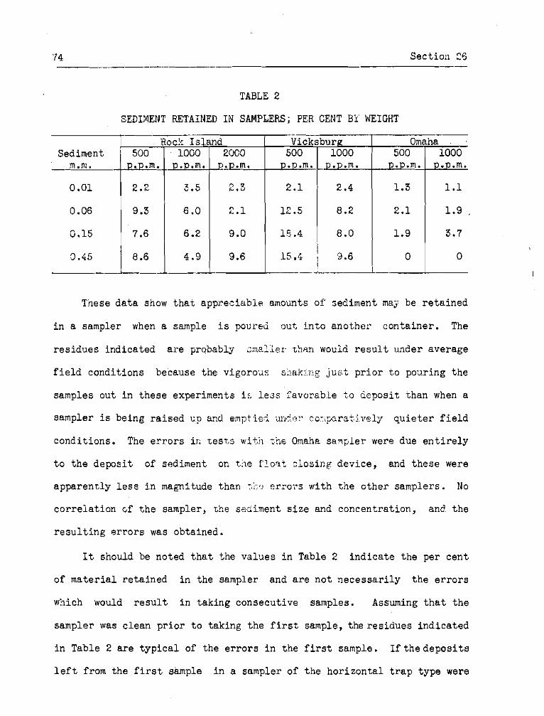
TABLE 2
SEDIMENT RETAINED I N SAMPLE-RS; PER CENT Bi WEIGHT
Tiese d a t a show t h a t appreciab1.e amounts of sediment ma;? be r e t a i n e d
i n a sampler when a sample i s poured out, i n t o another con ta ine r . The
r e s idues indica ted a r e pmbably c rne lk r . t h n would r e s u l t under average
f i e l d condi t ions because the vigorou:.. shaltjiig j u s t p r i o r t,o ponring t h e
samples out i n these experiments i: l e a s favorsb~le t o depos i t than when a
sampler i s being r a i s e d up arkd ernpt.icl, anr'er. cc?iperaSi17~1y q u i e t e r f i e l d
condi t ions . The e r r o r s i r . tesT,s i ;he Omaha sanp le r .were due e n t i r e l y
t o t'ne depos i t of sediment on t.>e f!osf c1osir.g device , and these were
apparent ly l e s s i n magnitude than t.::.: e r r o r s with t h e o the r samplers. No
c o r r e i a t i o n cf t h e sampler, t he seciirnent s i z e and concentrat ion, and t h e
r e s u l t i n g e r r o r s was obtained.
I t should be noted t h a t fne va lues i n Table 2 i n d i c a t e t h e per c e n t
of m a t e r i a l r e t a ined i n the sampler and a r e n o t n e c e s s a r i l y t h e e r r o r s
wbich would r e s u l t i n tak ing consecutive samples. Assuming t h a t t h e
sampler was c lean p r i o r t o taking t h e f i r s t sample, t h e r e s i d u e s i n d i c a t e d
i n Table 2 a r e t y p i c a l of t he e r r o r s i n the f i r s t sample. I f t h e d e p o s i t s
l e f t from the f i r s t sample i n a sampler of t h e ho r i zon ta l t r a p type were
'tioc!r I s land Vicksburg Sediment - . 1::
0.01
-- Omaha . ,
0.15 7 . 6
l O G O ... ..m.
3.5
6 .O
500 ..p.m.
2.1
12.5 0.06
500 ..p.m.
1.3
2.1
1 .9
20CO ;.p.m.
2 . 3
2.1
1000 D . P . ~ .
2.4
8.2 9.3
1000 P . P . ~ .
1.1
1 .9 ,
3.7 6.2 9.0 1 14.4 8.0
washed out by t h e flow through t h e tube before t ak ing the fol lowing
samples, t h e residues would a l s o be representa t ive of condit ions f o r sub-
sequent samples. In hor izonta l tube sampler i f previous samples a r e n o t
e n t i r e l y cleaned out , and i n samplers l i k e t h e Rock I s l and type, where no
cur ren t s flow through t h e container , (.he deposi t s 'rom one sample washes
out more o r l e s s i n t o subsequent samples, with a general tendency t o in -
crease samples of low concentration and decrease those of high concelltra-
t ion . However, i f t h e same samples were more thoroughly cleaned out than
o the r s , i n some cases high concentrat ions would be increased and low ones
decreased. Much more extensive research would be necessary t o evaluate
the importance of e r r o r s due t o t h i s cause i n stream observations.

76 Section 27
27. Nature of tests--The f i l l i n g ac t ion of a number of suspended
sediment samplers of the slow f i l l i n g , r i g i d conta iner type was gtudied
i n var ious sampling depths and stream v e l o c i t i e s . The t e s t was designed
t o secure bas ic information necessary i n making a t h e o r e t i c a l ana lys i s of
t h e depth-integrat ibn method of sampling a v e r t i c a l a s performed by two
common samplers, and t o allow a p r a c t i c a l co r re la t ion of t h e r e s u l t s of
the t e s t s of various entrance condit ions, presented previously i n t h i s
r epor t , with the a c t u a l f i l l i n g c h a r a c t e r i s t i c s of e x i s t i n g samplers.
The t e s t s of the entrance condit ions showed t h a t the sampling o r f i l l i n g
r a t e was one of the most important fact,ors a f f e c t i n g the accuracy of t h e
sedlment concentrat ions i n the samples co l l ec ted .
These t e s t s of samplers invol.ved the determination of:
a . F i l l i n g c h a r ~ c t e r i s t i c s i n s t i l l water. -
b. I n i t i a l inrush o r e f f e c t of i n i t i a l pressure d i f f e r - en t i ay .
c . Effect iveness of f l l l i n j r a t e adjustments such a s ~ a r ~ i ; . ~ s i z e of in.take and s i z e of ?ir exhaust.
d . Effec t of lowering and r a i s i n g a b o t t l e type sampler upon Xts f i l l i n g r a t e .
e . Effec t of stream veloci ty on f i l l i n g r a t e s . .-
28. Samplers t e s t ed and t h e i r a l t e r a t i o n s for-test--The samplers
t e s t e d represent types ofslow f i l l i n g samplers and, except f o r t h e h a z i e r
sampler, which is a r e l a t i v e l y new design, have been extensively used i n
sediment inves t iga t ions . In making t h e t e s t s it was necessary t o open o r
c lose the sampler a t any des i red depth o r time and the samplers were
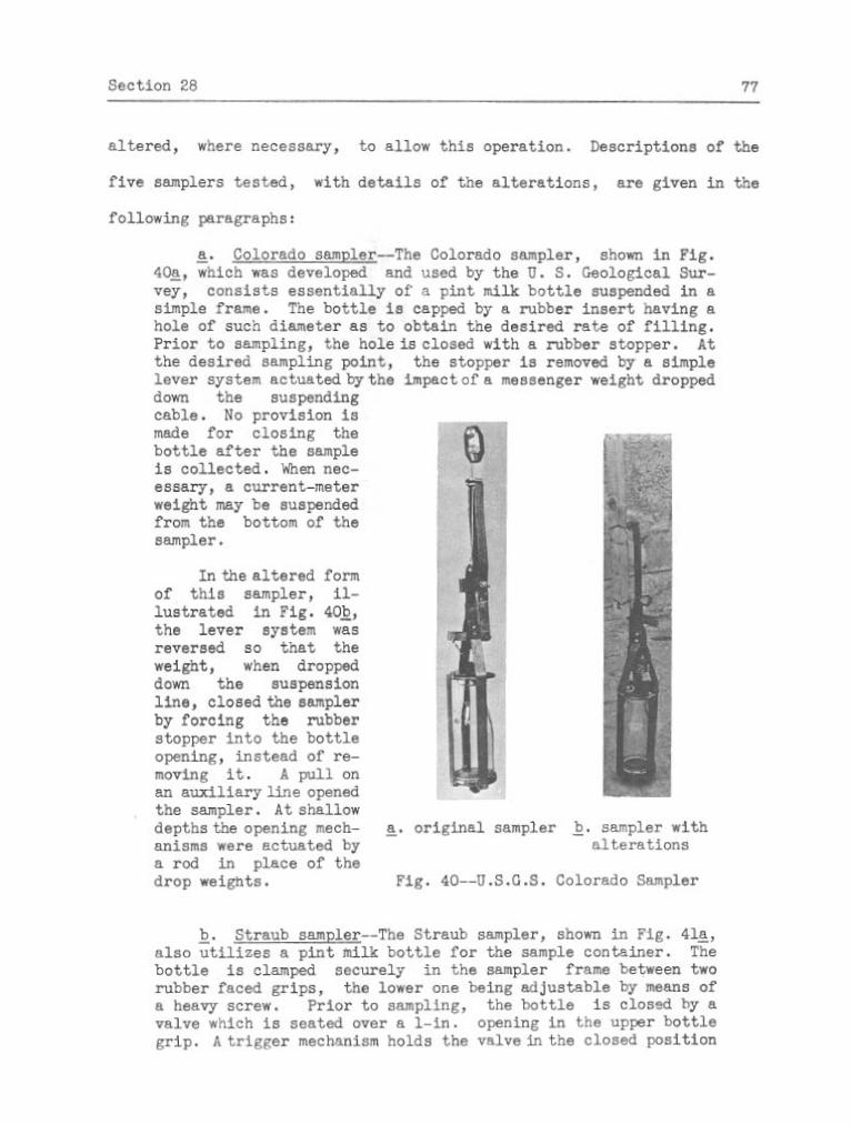
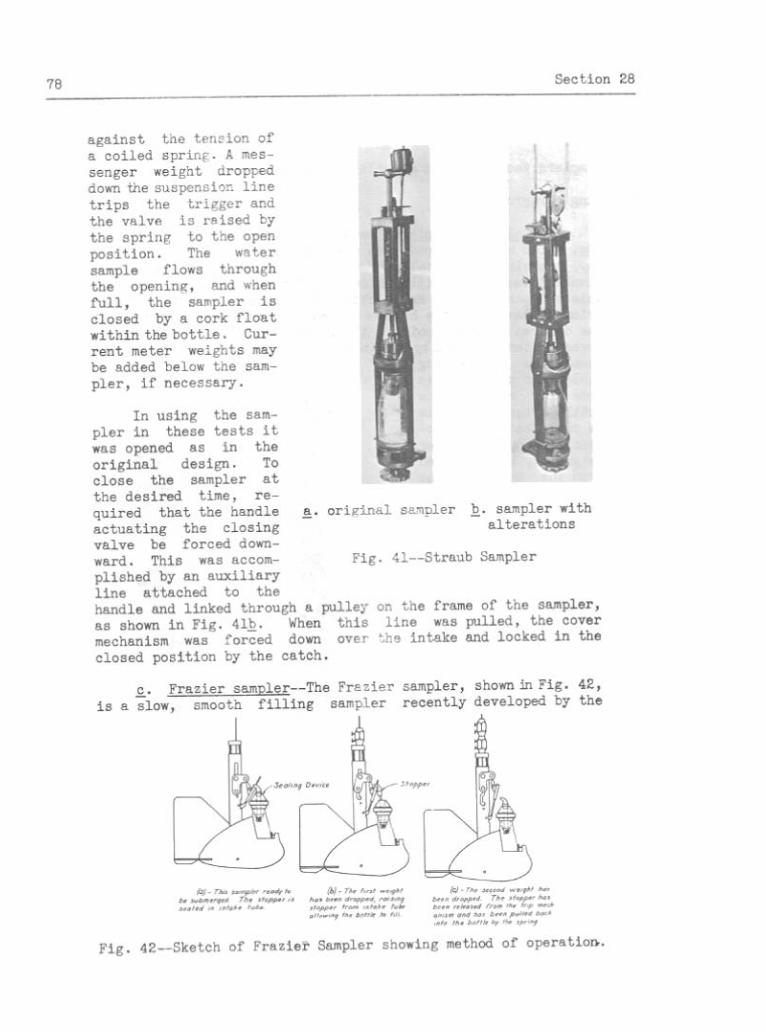
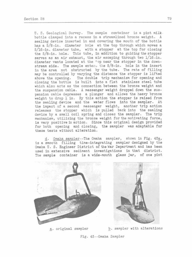
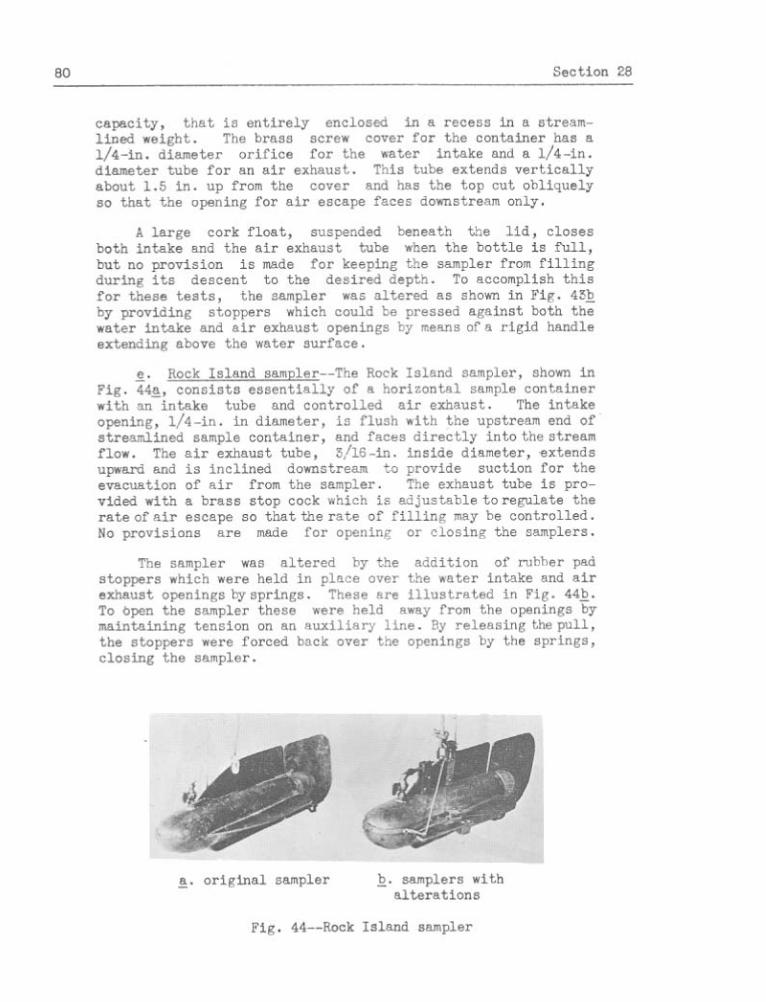

Sect ion 29 81
29. Tes t procg+ure--The procedure i n making t h e t e s t w i l l be de-
sccihed i n d i v i d c a l l y f o r t h e th ree b a s i c condi t ions considered.
a . F i l l i n e charnctg~:riics i n s t i l l water--The t e s t s i n s t i l l water were r a d e i n an abandoned quarry where depths g r e a t e r than SO f t . were a v a i l a b l e . An i c e cover f a c i l i t a t e d t h e work. The samplers were ~l:::pended by a c a b l e from a winch which r e s t e d upon t h e i c e ant: p:r,xitted l c rer ing and r a i s i n g the samplers a s des i r ed through holes o r s l o t s c u t i n t h e i c e .
For a s e l e c t e d depth t h e f i l l i n g d a t a f o r a sampler was secured by lowering the closed sampler t o t h e d e s i r e d po in t and then opening Tor ii s h o r t period of time. The per iods of time sliowed f o r f i l l i n g var ied from 1 sec. up t o a time necessary t o f i l l t h e con ta ine r . The volume of each sample a s measured i n il gr:lJuated cy!.inder was p lo t t ad a g a i n s t t h e corresponding f i l l i n g time producing f i l l i n g curves whose s lopes r ep resen t f i l l i n g r a t e s . This ~ l ' o c s d u r e was followed f o r a number of depths t \ r i th e r c h s ~ . n p l e r .
For t h e Rock Is land and F r a z i e r samplers t h e e f f e c t of t h e s i z e of t h e a i r exhaust opening and of t h e s i z e of t h e i n t a k e opening, r e spec t ive ly , were s tudied us ing t h i s same procedure.
b. V e r t i c a l t r ancs - -Ef fec t of v e r t i c a l motion of t h e colorado sampler upon i t s f i l l i n g r a t e was determined f o r a l i m i t e d range of condi t ions . As with the f i l l i n g de terminat ions i n s t i l l water, t h e f i l i i r g r a t e s were n e c e s s a r i l y determined i n d i r e c t l y from a time-volume r e l a t i o n s h i p e s t a b l i s h e d by a nimber of i nd iv idua l observat ions. Each observat ion, with sampler descending, cons is ted of lowering t h e open sampler a t a uniform r a t e , 1 o r 2 ft.:'sec. used i n these t e s t s from t h e s u r f a c e t o a so l ec t ed depth where the sampler was closed. By secu r ing a number of samples a t d i f f e r e n t depths , corresponding t o t h e var ious timss allowed f o r f i l l i n g , t h e f i l l i n g r a t e was determined.
Indiv idual t e s t s with sampler ascending were made by f i r s t lowering the c losec zamy;:e!: bclow tine se lec ted dept,h of opening. The mi fo rm r a t e of r a i s i n g wan then e s t a b l i s h e d , rind t h e sampler was opened a s i t passed t h e des i r ed depth . It was l e f t open f o r a lmown period of t ime, which e s t ab l i shed t h e depth range smnipled. A s e r i e s of such samples, d i f f e r i n g only i n time allowed f o r f i l l i n g .1r6 consequently the depth a t which the sampler was c losed , >#as ohtained f o r each of tvio depths of opening viitn each of two r a t e s of r a i s i n g .
c. F' lowin~ water--The test .s t o de t e rn ine t h e e f f e c t of s t ream veloci ty upon the sampler f i i l i n g r a t e s were made i n a l a r e e flume 10 f t . wide and. 114 f t . long, which was equipped

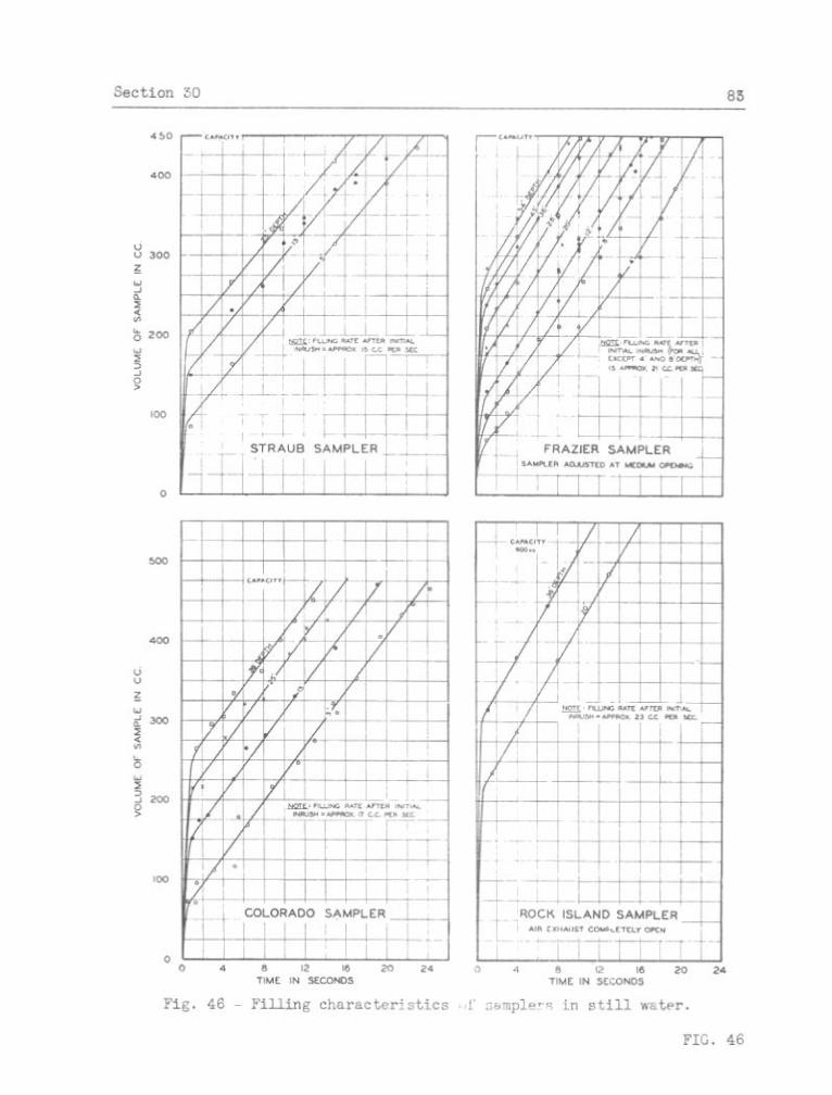

84 Sect ion 30
a. I n i t i a l inrush--Immediate1 a sampler i s opened, an in rush of water occurs, which i s vo i\, umetr ica l ly a funct ion of t h e depth of submergence, and may reqresent a considerable per- centage of t h e t o t a l sampler capaci',ty. It i s termed i n i t i a l in rush i n t h i s r e p o r t because of i t s high r a t e of inflow.
b . Normal fill ing--The average k i l l i n g r a t e , a f t e r t h e i n i t i a l inrush , i s s u b s t a n t i a l l y a conbtant f o r any one sampler and i s unaffected by t h e depth of sampling. It may be e i t h e r uniform and smooth, i f a separa te air exhaust i s provided, o r i n t e r m i t t e n t i f a s i n g l e opening must serve f o r both a i r escape and sample in take .
T'ne i n i t i a l in rush represents the volume decrease of t h e a i r wi th in
a sampler, corresponding t o i t s compression from atmospheric pressure t o
t h e *ydros ta t i c pressure at the p a r t i c u l a r s b p l i n g depth. During t h i s !
a c t i o n no a i r escapes and the f i l l i n g r a t e i s \ a func t ion of the pressure
d i f f e r e n t i a l from outs ide t o i n s i d e ' t h e sam*ler. A t t h e i n s t a n t t h e
sempler i s opened, t h i s pressure d i f f e r e n t i a l i s a maximum, equal tb t h e
f u l l hydros ta t ic pressure a t t h e sampling poin , and, consequentZy, t h e t f i l l i n g r a t e i s a maximum. Both pressure d i f f e r e n t i a l and f i l l i n g r a t e
e r e quickly reduced a s t h e air i n t h e sampler i s compressed, and when the
pressure d i f f e r e n t i a l reaches zero, t h e f i l l i n g becomes t h e normal a c t i o n
invoi.ving a displacement of a i r . Tne i n i t i a l , inrush period was found t o
2 s less than 1 sec., b u t because df t h e i n a b i l i t y t o c o l l e c t samples f o r
zhor te r periods, t h e quan t i ty c o l l e c t e d d d i n g t h e f i r s t second a f t e r a
sampler was opkned was considered a s r e su l t iAg , from i n i t i a l inrush .
Af ter the i n i t i a l inrush, and the compression of the a i r t o a
pressure p r a c t k a l l y equal t o t h e hydros ta t i c pressure a t t h e d e p t h i s
c:mpleted, the f i l l i n g takes place as a displacenent of a i r caused by t h e
i~uoyancy of the air. For each volume of water e n t e r i n g the sampler an
nquel volume of a i r escapes and t h e f i l l i n g r a t e i s a f f e c t e d by t h e
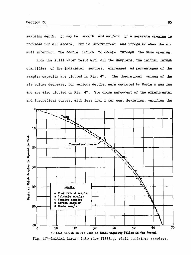
Section 30 85
sanpling depth. It may be smooth and uniform i f a separa te opening i e
provided f o r a i r escape, but i s i n t e r m i t t e n t and i r r e g u l a r when t h e a i r
must i n t e r r u p t t h e sample inflow t o escape through the same opening.
From the s t i l l water t e s t s with a l l t he samplers, the i n i t i a l inrush
q u a n t i t i e s of t h e individual samples, expressed a s percentages of t h e
s ~ m p l e r capaci ty a r e p lo t ted i n Fig. 47. The t h e o r e t i c a l va lues of the
a i r volume decrease, f o r various depths, were computed hy Boyle's gas law
and a r e a l s o p l o t t e d on F ig . 47. The c lose agreement of the experimental
and t h e o r e t i c a l curves, with l e s s than 1 per cen t deviat ion, v e r i f i e s t h e
I n i t i a l Inmah i n Pmr Cant of Total Capoi ty P i l lad in Om 80oond
Fig. 47-- In i t ia l i n w s h i n t o slow f i l l i n g , r i g i d container samplers.
86 Sect ion 30
a n a l y s i s of t h e i n i t i a l in rush phenomena. The s l i g h t l y g r e a t e r experi-
mental va lues of i n i t i a l in rush may be a t t r i b u t e d t o t h e f a c t t h a t t h e
quan t i ty c o l l e c t e d during t h e f i r s t second of sampling was considered t h e
volume of i n i t i a l in rush whereas, undoubtedly, it entered t h e sampler i n
l e s s than 1 sec . The curve, represent ing d a t a with a l l t h e samplers
t e s t e d , i n d i c a t e s t h a t t h e i n i t i a l inrush-sampling depth r e l a t i o n s h i p
e s t a b l i s h e d , i s appl icable t o a l l e x i s t i n g samplers of t h e r i g i d con-
t a i n e r type .
The i n i t i a l in rush phenomenais an important c o n s i d e r a t i o n i n sampling
with slow f i l l i n g r i g i d conta iner samplers when t i e sampler i s opened a t
some po in t below t h e su r face . There a r e two ac t ions t h a t may r e s u l t i n
se r ious e r r o r s i n t h e sample col lectzed.
a . The excessive sampling r a t e during t h e i n i t i a l i n rush per iod may r e s u l t i n a segregat ion of' t h e sediment from t h e water and a sample too low i n concentrat ion. Dependent upon p a r t i c l e s i z e , t h i s phenomena may be s e r i o u s a s determinedin t h e s tudy of en t rance condi t ions presented i n Chapter 111.
b. With t h e opportuni ty f o r a r e l a t i v e l y l a r g e port ion of t h e sample con ta ine r t o be f i l l e d i n l e s s than 1 sec. t h e sample secured i s n o t a t r u e t i ne - in t eg ra t ed sample and may n o t r ep resen t an average value of sediment concent ra t ion a t t h e sampling poin t . O r , when used f o r t h e depth- in tegra t ion method where the sampler i s t o c o l l e c t a szmple only while being r a i s e d , t o o l a r g e a port ion of t h e sample w i l l be c o l l e c t e d near t h e bottom. I n t h i s case, t h e inc rease i n concent ra t ion r e s u l t i n g tends t o o f f s e t t h e decrease a s described under above.
The normal f i l l i n e ac t ion of t h e samplers n o t provided with sepa ra t e
a i r exhausts was i n t e r m i t t e n t and i r r e g u l a r because of the a i r escape.
This a c t i o n apparent ly consis ted of a period dur ing which the f i l l i n g
dec reases and f i n a l l y s tops , followed by an i n s t a n t of a i r escape o r
bubbling. A t times, e s p e c i a l l y i n s t i l l wa te r , t he a i r escape was delayed,
poss ib ly because of t h e sur face t e n s i o n o f t h e water a t t h e sampler mouth,

Section 3 1 87
and t h e r e would be a period of n e i t h e r f i l l i n g nor a i r escape. This
clogging ac t ion was prevented i n t h e t e s t s by a g i t a t i n g t h e samplers t o
a l low normal i n t e r m i t t e n t f i l l i n g . This d i f f i c u l t y has been experienced
by s e v e r a l f i e l d observers us ing t h e samplers under a c t u a l s tream con-
d i t i o n s .
With t h e Omaha sampler, although it was provided with separa te a i r
exhaust t o allow smooth uniform f i l l i n g , the f i l l i n g a c t i o n i n s t i l l water
and i n low stream v e l o c i t i e s was i n t e r m i t t e n t and s u b j e c t t o the clogging
ac t ion . This may be a t t r i b u t e d t o a tendency f o r t h e a i r t o escape and t h e
water t o e n t e r through both t h e a i r exhaust tube and t h e in take o r i f i c e .
With the Rock Is land sampler, and i n o the r slow f i l l i n g samplers of
similar design, a condit ion i n f i e l d operat ion was observed which should
be avoided. When t h i s sampler becomes t i l t e d nose downward, a i r i s
trapped i n t h e back end of the sample container and cannot escapen The
sampler may f i l l u n t i l water i s pass ing through and ou t t h e air exhaust ,
y e t t h e sample volume w i l l no t i n d i c a t e t h a t t h e sampler i s e n t i r e l y
f i l l e d . Under t h i s a c t i o n the re e x i s t s t h e opportunity f o r deposi t ion of
sediment i n the sampler, r e s u l t i n g i n an abnormally high sediment concen-
t r a t i o n .
31. Effect iveness of f i l l i n g r a t e adjustment--The F r a z i e r and Rock
Is land samplers were t e s t e d t o determine t h e e f fec t iveness of the ad jus t -
ment provided t o r e g u l a t e t h e i r f i l l i n g r a t e s . On t h e Fraz ie r , t h e
e f f e c t i v e s i z e of t h e mouth may be changed by varying t h e d i s t ance the
stopper i s ra i sed from t h e mouth. On the Rock I s l and , t h e a i r exhaust
may be t h r o t t l e d by a s t o p cock valve.
88 Sect ion 32
Resul t s of t h e t e s t s with tine F raz ie r sampler ad jus t ed t o l a r g e ,
medium, and small openings a r e shown by Fig. 48. The f i l l i n g r a t e s o f ,
46, 21, and 5 cc./sec., respec t ive ly , show pos i t ive a n d e f f e c t i v e c o n t r o l .
These d a t a were secured a t a depth of 45 f t . , but d a t a a t a depth of
20 f t . gave corresponding r e s u l t s . The f i l l i n g r a t e a f t e r i n i t i a l i n rush
f o r each adjustment of t he stopper does no t vary with depth. This i s
a l s o shown by the t e s t d a t a presented i n Sect ion 30.
The r e s u l t s with the Rock Is land sampler f o r two adjustments of t h e
a i r exhaust a r e presented i n Fig. 49. From a f i l l i n g r a t e of 23 cc./sec.
with the a i r vent open, t he r a t e was reduced t o 15 cc./sec. by tu rn ing
the va lve t o the ha l f c losed pos i t ion .
The d e s i r a b i l i t y of t h r o t t l i n g the f i l l i n g r a t e of t he Rock Is land
sampler i s quest ionable, however, Secause of t h s e r r o r s in sediment con-
cen t r a t ion which were found t o o-cur from an in take r a t e below normal a s
described i n Section 14. Even without t h r o t t l i n g t h e a i r exhaust, t h e
sampling r a t e would be lower than the des i r ed normal r a t e .
32. E f fec t of lowerine and r a i s i n g t h e c o l o r a d o Sampler upon f i l l i n g
charac ter i s t ics - -The Colorado sampler, s e l e c t e d a s a sampler commonly used
i n t h e depth- in tegra t ion method of sampling, was t e s t e d t o determine i t s
f i l l i n g c h a r a c t e r i s t i c s under various condi t ions of lowering and r a i s i n g .
The t e s t . procedure i s described i n Sec t ion 23. The t e s t s withchedescend-
ing sampler c o n s i s t e d o f t w o s e r i e s o f s a s ~ p l e s co l l ec t ed a s the sampler was
lcwered from the sur face a t r a t e s of 1 f t . / s e c . and 2 f t . / s e c . The t e s t s
with the ascending sampler consis ted of *.-o s e r i e s of samples c o l l e c t e d
a s t h e samp!.er was r a i s e d from each of two openinc depths a t r a t e s of 1
f t . / s e c . and 2 f t . / s e c . Resul t s of t hese t e s t s a r e presented i n Fig. 50.

Section 32 89
Fig. 48 - Effect of size of opening in Frazier sampler upon filling rate.
Fig. 49 - Effect of air exhaust adjustment upon filling rate of Rock Island sampler in still water.
FIGS. 48 & 49
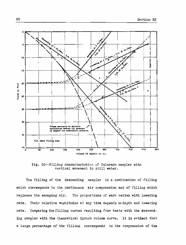
90 Section 32
Volume of 9amnlo in a c ,
Fig. 50--Filling c h a r a c t e r i s t i c s of Colorado sampler with v e r t i c a l movement i n s t i l l water.
The f i l l i n g of the descending sampler is a combination of f i l l i n g
which corresponds t o the continuous a i r compression and of f i l l i n g which
replaces the escaping a i r . The proport ions of each va r i e s with lowering
r a t e . Their r e l a t i v e magnitudes a t any time depends ondepth and lowering
r a t e . Comparing t h e f i l l i n g curves r e s u l t i n g from t e s t s with the descend-
in^ sampler with t h e t h e o r e t i c a l inrush volume curve, it i s evident t h a t
a l a r g e percentage of the f i l l i n g corresponds t o the compression of t h e
air volume i n the sampler. For the 2 f t ./sec. lowering r a t e t h e r e was no
appreciable a i r escape u n t i l a 15-ft . depth was reached. From t h a t l e v e l
downward t h e r a t e of pressure equal iza t ion was more rapid , r e l a t i v e l y ,
allowing time f o r a i r r e l ease and normal f i l l i n g . W i t ' ' a decreased r a t e
of l o w e r i n ~ , i l l u s t r a t e d by t h e 1 f t . / sec . curve, the time f o r a i r r e l ease
i s g rea te r , al lowing normal f i l l i n g t o occur a t shallow depths .
The average sampling r a t e i s s l i g h t l y g rea te r f o r t h e 2 f t . / s ec .
r a t e of lowering than the 1 f t . / sec . but the d i f fe rence is probably no t
s i g n i f i c a n t because of considerable devia t ion of individual observations
from t h e general curve f o r the 1 f t . / sec . lowering r a t e .
The f i l l i n g o f t h e ascending sampler, a f t e r in rushhas taken place, i s
e n t i r e l y an a c t i o n of displacement of the escaping and expanding air, and
thus i s s i m i l a r t o the normal f i l l i n g ac t ion of a sampler s t a t i o n a r y a t
a depth a f t e r i n i t i a l inrush has occurred. In the t e s t s made the i n i t i a l
inrush was volumetrical ly propor t ional t o t h e depth a t which t h e sampler
was opened, t h e sane a s i n the t e s t s with t h e sampler s t a t i o n a r y a t a
depth. The r a t e s a f t e r the inrush a re p r a c t i c a l l y uniform and, except
f o r the 2 f t . / s e c . r a i s i n g r a t e from the 20 f t . depth, a r e appreciably
higher than t h e co r respnnd in~ r e s u l t s with no v e r t i c a l movement.
Further a n a l y s i s of these r e s u l t s and genera l conclusions a r e no t
attempted because t h e f i l l i ~ g a c t i o n o f t h e Colorado sampler with v e r t i c a l
movement i s complicated by t h e disturbance of the mechanism above t h e
sampler mouth. Considering t h e va r i a t ions i n individual observations and
the a r t i f i c i a l a g i t a t i o n found necessary t o insure f i l l i n g , these d a t a
serve only t o show t'nat f o r t h e Colorado sampler the f i l l i n g r a t e may be
considered constant f o r a l l p r a c t i c a l r a t e s of r a i s i n g and lowering.
92 Sect ion 33
33. Effec t of stream v e l o c i t y on f i l l i n g rates--The r e s u l t s of t h e
f i l l i n g r a t e determinat ions with t h e samplers i n v a r i o u s stream v e l o c i t i e s
a r e shown by Fig. 51. The f i l l i n g r a t e s p l o t t e d f o r each r e spec t ive
stream v e l o c i t y r e p r e s e n t ' t b e f i l l i n g a f t e r i n i t i a l i n rush obtained a s an
average of from 10 t o 15 indiv idual samples which v a r i e s over a range of
about 20 per cent .
From these r e s u l t s it i s seen t h a t t h e Rock I s l a n d sampler, with i t s
mouth f ac ing i n t o t h e :.s:tr,eam, i s t h e only o n e o f t h e samplers t e s t e d which
e x h i b i t s a d e f i n i t e r e l a t i o n s h i p between f i l l i n g r a t e and stream v e l o c i t y .
With t h e S t raub , F raz i e r , and Colorado samplers, with in t akes f ac ing
normal t o the stream, t h e stream v e l o c i t y d id n o t s i g n i f i c a n t l y a f f e c t
the f i l l i n g r a t e s , Any s l i g h t vari:!tionc i n f i l l i n g r a t e which these
samplers appeared t o have with var ious strrtan~ ve loc i t i c r : a r e a c c i d e n t a l
and probably r e s u l t from i n d i r e c t e f f e c t s such a s a g i t a t i o n and b e t t e r
a i r escape. With t h e Omaha sampler, rhose mouth a l s o faced normal t o t h e
stream, but whose a i r exhaust was faced downstream t h e r e wasnoapprec iable
e f f e c t of the stream v e l o c i t y upon t h e f i l l i n g r a t e .
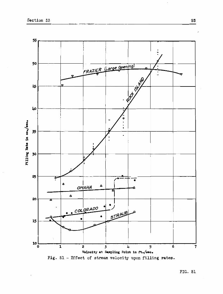
Section 33 93

94 Sect ion 34
VII. SUMMARY AND CONCJJSIONS
34. Sumnary of sampler studies--Report No. 1 of t n i s p r o j e c t in-
cluded a reviewaf suspended sediment samplers, which consisted of c l a s s i -
f i c a t i o n , desc r ip t ions , and general discussions of t h e samplers. Certain
f e a t u r e s of sampler design and operat ion were suspected of a f f e c t i n g the
accuracy ofs,mples co l l ec ted and t h e general a d a p t a b i l i t y o r t h e samplers.
Although these f e c t u r e s and t h e i r e f f e c t s could n o t be r o l i a b l y analyzed
i n t h a t review, they were l i c t c d a s f o l l o v ~ s :
a . Disturbance of normal stream flour and t h e tendencies toward segregction of water and sediment a s the sample i s bcing c o l l e c t e d .
b . F i l l i n g due t o i n i t i a l pi-essure d i f f e r e n t i a l , r e s u l t i n g - i n :i non-representat ive f i l l i n g r a t c .
c . Non-removable sample cen ta inc r s 1vhj.ch tend t o loose - sediment when the sample i s t r ans fe r red t o another container .
d . Inctantanoous s<m.? l in~ a c t i o n a s r c l a t o d t o f luc tua- - t i o n s of sediment concentration i n t h e stream a t t h e s m p l i n g p o i n t .
o . I n a b i l i t y t o c o l l e c t a ocaple closc t o t h c bcd r e s u l t - - i n& i n an inadequate sample of the l a r g e r ma te r i a l bcing trano- por ted .
f , Nixing of sample with wter-sediment above tine sampling - po in t r e s u l t i n g i n an unroprcsentat ive sample.
Features a, b, and c have been studied experimentally and the r e s u l t s a r e
presented by this r e p o r t .
The disturbance of normal stream f l o v ~ a t t he sampler entmucc and
deposi t ion during the flow through a hor i zon ta l cy l inde r have been found
t o have considerable e f f e c t upon the sediment concentrat ion of samples.
The f i l l i n g due t o i n i t i a l pressure d i f f e r e n t i a l , termed i n i t i a l inrush
i n t h i s r e p o r t , was inves t iga ted i n t h e experimental s tudy of the sampler
Section 35 95
c h a r a c t e r i s t i c s . Conclusion; from these s tud ies a r e presented i n sub-
sequent sec t ions .
In Report No. l w a s pointzd out the p o s s i b i l i t y of obta in ing w i t h an
instantaneous .uampler a v d u e of sediment concentrat ion n o t r ep resen ta t ive
of the average a t t h a t po in t due t o the f l u c t u a t i o n s i n sediment concen-
t r a t i ~ n caused by turbulence. These f l u c t u a t i o n s were no t s tudied i n
t h i s projec t and s ince the few experimental d a t a ava i l ab le do no t de f ine
t h e magnit~tde of thcnc e r r o r s nor the condi t ions under which they become
important, t h c e r r c r s c : ~ be determined apgroximately talting dupl ica te
samples m d comparing t h e i r concentrat ions. Under condi t ions where i m -
po r t an t d i f ferences a r e found, a s u f f i c i e n t number of samples should be
t a k e n t o o b t a i n a reasonably accuratc value f o r the average concentrat ion.
The i n a b i l i t y t o c o l l e c t a snmplo c l o s e t o t h e stream bcd is a design
f e a t u r e a s a r e various o thcr minor f a c t o r s a f f e c t i n g t h e a d a p t a b i l i t y of
a sampler. The necess i ty of sampling c lose ts the c t r e m bed, i f repre-
san ta t ive p a r t i c l e size-discharge r c l a t i o n s h i ~ i s t o be s e w e d , is d i s -
cussed i n Report 110. 9.
The intermix in^ of water-sediment from above a s m p l i n ~ : po in t i n t o a
sample is obviously undesirable when a s m p l e represent ing a p a r t i c u l a r
depth is des i red . It i s pr imar i ly a considerat ion i n sampler design.
85. Studri of smwler on t rmce conditions--The f low condit ions of n
suspended sediment smp1.o approaching and entoring a sampler have been
analyzed and the tendencies toward segregation of t h e water and sediment
as a r e s u l t of de f l ec t ion o r d i ~ t u r b c ~ n c e of t h e flow have been evaluated
f o r the r e s u l t i n g e r r o r s i n t h e sediment concentrat ion of t h e samples.
9 6 -- -- Section 35
From these s t u d i e s , e r r o r s of ser ious magnitudes were found t o r e s u l t
from c e r t a i n , no t unusual, entrance condit ions and were found t o vary
s i g n i f i c a n t l y with t h e f a c t o r s l i s t e d below:
a. Size of sediment--The s i z e of t h e sediment p a r t i c l e s was es t ab l i shed a s one of the more important f a c t o r s a f f e c t i n g the magnitude of e r r o r s which r e s u l t froin undes i rable in take ac t ion . The s i z e , 0.06 mm., approximately the upper l i m i t o f Stokes' law, appeared a s a c r i t i c a l s i z e above which t h e e r r o r s increased rap id ly i n magnitude a s the sediment s i z e increased, and below t h e 0.06 mm. s i z e the va r i a t ion i n the magnitude of e r r o r s , a s t h e sediment s i z e var ied , was considerably l e s s . Below 0.06 mm. the e r r o r s f o r a l l condi t ions s tudied were l e s s than 10 pe r cent . For p a r t i c l e s l a r g e r than 0.06 mm., which a r e no t uncommon, the r e s u l t s have immediate p r a c t i c a l appl ica- t i o n i n proper sampler design o r se lec t ion .
b. Orienta t ion of sampler intake--I t nas found t o be es- s e n t i a l i n order t o c o l l e c t accurate samples, t h a t t h e samplcr mouth f a c e i n t o the stream. Al thou~h a nozzle fac ing d i r e c t l y i n t o the stream is the d e s i r a b l e condit ion, small dev ia t ions up t o 20° from t h i s o r i e n t a t i o n , as might occur a c c i d e n t a l l y in the opera t ion of a sampler, have l i t t l e e f f e c t upon tho sediment concentrat ion.
c . Sampline-;ate_--The sampling r a t e was f o u ~ d t o be the most impor tant f a c t o r i n the opera t ion of a slow f i l l i n g sampler, f o r sorious e r r o r s may occur, p a r t i c u l a r l y when the sampling r a t e is appreciably slower than the stream veloci ty . The sampling r a t e must e i t h e r be con t ro l l ed s o t h a t t h e ve loci ty i n the mouth i s approximately equal t o the normal stream veloc- i t y a t t h e sampling p o i n t o r the sampler must be c a l i b r a t e d f o r i ts r a t i o of in take ve loc i ty t o stream ve loc i ty and correc t ion curves determined s i m i l a r t o t h e curves shown i n Fig. 13. Any c o n t r o l of a sampling r a t e o r c a l i b r a t i o n of a slow f i l l i n g sampler i s complicated by t h e extremely rapid ent rance of water dur ing the i n i t i a l pressure equal iza t ion t h a t has been shorn t o occur within l e s s than 1 sec.
d . Shape of samvler in takes- - I t was found t o be e s s e n t i a l t h a t -the mouth of the sampler be extended upstream from any d e f l e c t i o n o r d is turbance of the flow caused by t h e body of t h e sampler. No abso lu te values of t h e required l eng th of t h i s extension were determined b u t i t was demonstrated t h a t a mouth f l u s h with t h e body of the sampler i s no t s a t i s f a c t o r y . The a c t u a l shape of t h e nozzle should approximate t h e streamlined shape of the standard nozzle a s nea r ly a s p r a c t i c a l but n o t a t a s a c r i f i c e of s i m p l i c i t y and ruggedpess as small v a r i a t i o n s i n shape of the nozzle were found t o be unimportant.

Sect ion 36 97
e . Area of sampler---The a r e a of the sampler mouth, a l though found t o a f f e c t somewhat the nagnitude of e r r o r s t h a t do occur < id not a f f e c t t he accuracy of samples c o l l e c t e d under t h e proper ly con t ro l l ed standard sampling condit ions. The tend- ency was toward l a r g e r e r r o r s with smaller mouth s i z e s . I t i s more important t h a t t he extreme leading edge of t he sampler mouth, as i l l u s t r a t e d i n Fig. 17, be used i n computing the a r e a t o be used i n determining t h e i n t a k e ve loc i ty . The a r e a of t he mouth of a slow f i l l i n g sampler should be determined from con- s i d e r a t i o n s of t h e volume of t h e samples t o be co l l ec t ed , t h e d e s i r e d dura t ion of sampling time, and the range of stream v e l o c i t i e s .
Al.though the f a c t o r s Listed above have been d iscussed p r imar i ly a s
p e r t a i n i n g t o slow f i l l i n g or t ime- in tegra t ing samplers, t he considera-
t i o n s a r e appl icabie a l s o t o the instantaneous ho r i zon ta l samplers. The
conception of t he phenomena of s t reaml ine d e f l e c t i o n and d is turbance i s
a l s o applicable t o t h e study of t h e v e r t i c a l t r a p instantaneous samplers.
36. F l o w t h r o u ~ h h o r i z o n t a l cylinders---The experiments described
here in have shown that under c e r t a i n condi t ions depos i t s may occur i n
samplersof t h e ho r i zon ta l t r a p type, due t o the reduct ion of the v e r t i c a l
componen.ts of t h e momentary cu r ren t s of t h e stream a s i t flows through
t h e cy l inde r . The s t u d i e s made were i n s u f f i c i e n t t o eva lua te the in-
portance of these e r r o r s .
37. Loss of sediment i n s a m p l e t r a n s f e r from nonremovable con-
tainers--The s tudy of t h e amount of sediment adhering t o nonremovable
conta iner samplers when t h e samples a r e pcured out i n d i c a t e that even
under favorable condit ions of a g i t a t i o n , t hese amounts may be of appreci-
ab le magnitude and under c e r t a i n condi t ions may lead t o e r r o r s of con-
s ide rab le magnitude.
The s t u d i e s were n o t s u f f i c i e n t t o de l imi t t h e condi t ions under
which e r r o r s of importance would occur.

08 Section 38
38. F i l l i n n c h z r a c t e r i s t i c s of s loa f i l l i n c samvlers--The f i l l i n g
chz ra , c t e r i s t i c s of f i v e ropresentc~tivo slow f i l l i n g samplers ac re d e t e r -
:nilled experiinentnlly. Two d i s t i n c t f i l l i n g ac t ions , a rapid inflow t o
equalize a i r a d water pressures ond a normal f i l l i n g a f t e r thc equaiiza-
t ion , were found t o be common t o the snmp1er.s of t h i s c l a s s .
When the samplers were opened a t a po in t below the s u r f m e tile
pressure equal iza t ion , terned i n i t i a l inrush , ,rvas found t o occur j.n one
second o r l o s s with no escape of a i r d u r i n ~ the a c t i o n ; the vol.me ol̂
v:atcr en te r ing being propor t ional t o the depth. This c c t i o n i s extremely
important i n the co l l ec t ion of t ine- in tegra ted samples. For exmple ,
Bo3-le's Law i n d i c a t e s t h a t a t a 34-ft. depth approximately 50 per cent of
the sampler capaci ty would be f i l l e d by t i i s i n i t i a l inrush volwne. 11n-
p o r t m t a l s o t c consirler is t n a t e r r o r s i n coi icsntrst ion tend tooccur
:~oceuso of t i e extensively high in take r a t e , a condition i.n the
labora tory stcdy of in take ac t ion , was f v u d t o be serious. The tvio
effr :cts , iiowevcr, uouclly tend t o o f f s e t ecch o ths r . In s t i l l \*~c te r , o r i f the samplcr o p c n i i l ~ does no t f ace i n t o the
stream, normal f i l l i n g a f t o r the i n i t i a l pressure equal iza t ion occurs n t a
%ore o r l e s s constant r a t e ; the ac t ion being t;encrally smooth and w i f o r m
i f the a i r escn:,as through a separate exhaust , 1mt i ~ l t e r n i t t e n t ~ ~ n d ir-
regular i f t h e a i r ond semple florr through a common opening. I f the sam-
p l e r f aces i n t o the strnear;!, t h e f i l l i n g r a t e log ica l ly vras fourld t o vary
with stream ve loc i ty . Although f i l l i n g r a t e adjustments were Eound t o be
e f fec t ive i n c o n t r o l l i n g the r a t e s , the procedure i s ques t ionable from t h e
standpoint of t h e mcuracy of the sedinent content of t h s samples co l l ec ted
w i t h i n t ake v e l o c i t i e s considerably below the normal streant. v e l o c i t i e s .
Sect ion 58 99
The f i l l i n g ac t ion of a common b o t t l e sempler was s tud ied under
vhr ious condi t ions of lov;cring and re.ising. Thc r a t e of f i l l i n g , wkvhetlier
a f t e r i n i t i a l in rush i f the sampler was lowered t o n p o i n t , opened and
f i l l e d whi le being r a i s e d , o r dur ing constant r a t e s of lowering and
r a i s i n g , rrns e s s e n t i a l l y constant . There d i d not appear t o be a substan-
c i a 1 d i f f e r e n c e i n f i l l i n g r a t e s under t h e var ious types of movement.
This . tes t was not comprehensive and t h e r e s u l t s a r e n o t necessa r i ly
cpplicc.ble t o bther types of slow f i l l i n g s m p l e r s used i n the dopth-
i i l tegra t ion metinod.