K-Series KlearVue Folding Platform Wheelchair Lift for ...K-Series® KlearVue™ Folding...
27
K-Series ® KlearVue™ Folding Platform Wheelchair Lift for Personal and Transit Use OPERATOR MANUAL 10/15/11 32DSS101.D ©2011 RICON CORPORATION All Rights Reserved U.S. and Foreign Patent(s) Pending Printed in the United States of America -PRINT- -HOME-
Transcript of K-Series KlearVue Folding Platform Wheelchair Lift for ...K-Series® KlearVue™ Folding...

K-Series®
KlearVue™ Folding Platform Wheelchair Lift for
Personal and Transit Use
OPERATOR MANUAL 10/15/11 32DSS101.D ©2011 RICON CORPORATION
All Rights Reserved U.S. and Foreign Patent(s) Pending
Printed in the United States of America
-PRINT-
-HOME-
32DSS101.D - i -
THIS RICON PRODUCT MUST BE INSTALLED AND SERVICED BY A RICON DEALER OR QUALIFIED SERVICE TECHNICIAN.
THE OWNER MUST REFER TO THIS MANUAL FOR OPERATING INSTRUCTIONS, THEN RETAIN IT FOR FUTURE REFERENCE BY RICON DEALERS OR QUALIFIED SERVICE TECHNICIANS THAT PERFORM MAINTENANCE.
Customer Name: Installing Dealer: Date Installed: Serial Number:

32DSS101.D - ii -
REVISION RECORD
REVISION PAGES DESCRIPTION OF CHANGE ECR/ECO
32DSS101. D
Update to Cover
6560
i Update to Customer information.
1-1 Update to Contact information.
1-2 Update to Warranty statement.
2-1, 2 Update to Safety Precautions.
2-3 Added Figure 2-4. Updated consecutive figures.
2-7 Update to Lift Operation.

32DSS101.D - iii -
TABLE OF CONTENTS
Chapter Page
I. INTRODUCTION ................................................................................................................... 1-1
A. RICON SERVICE SUPPORT .................................................................................. 1-1
B. K-SERIES LIFT WARRANTY ................................................................................. 1-2
C. SHIPMENT INFORMATION ................................................................................... 1-3
D. GENERAL SAFETY PRECAUTIONS ........................................................................ 1-3
E. MAJOR COMPONENTS ........................................................................................ 1-4
II. K-SERIES OPERATING INSTRUCTIONS ...................................................................... 2-1
A. SAFETY PRECAUTIONS ....................................................................................... 2-1
B. DAILY SAFETY CHECK ......................................................................................... 2-3
C. LIFT FUNCTIONS ................................................................................................. 2-3
D. CONTROLS AND INDICATORS ............................................................................. 2-4
Control Pendant ........................................................................................... 2-4 Interlock Indicator Light ................................................................................ 2-5 Circuit Breaker for Optional Door Operator ..................................................... 2-5 Control System Circuit Breaker ..................................................................... 2-5 Pump Solenoid LED Status Indicator ............................................................. 2-5 Main Circuit Breaker ..................................................................................... 2-6 Manual Backup Pump ................................................................................... 2-6
E. LIFT OPERATION ................................................................................................. 2-7
1. Entering Vehicle ............................................................................................ 2-8
2. Exiting Vehicle ............................................................................................... 2-8
3. Stowing Platform ........................................................................................... 2-9
4. Manual Operation .......................................................................................... 2-9
F. MAINTENANCE AND REPAIR NOTE .................................................................... 2-12
III. MAINTENANCE AND REPAIR .......................................................................................... 3-1
A. MAINTENANCE INFORMATION ............................................................................. 3-1
B. CLEANING ........................................................................................................... 3-1
C. LUBRICATION ..................................................................................................... 3-1
D. MAINTENANCE SCHEDULE .................................................................................. 3-2
E. K-SERIES DECALS .............................................................................................. 3-4
32DSS101.D - iv -
This page intentionally left blank.

1 - 132DSS101.D
I. K-SERIES® PERSONAL USE INTRODUCTION his manual provides operating and maintenance instructions for the Ricon K-Series® Klear-Vue™ Personal Use wheelchair lift. The platform on the K-Series® splits horizontally to re-duce the overall lift height when stowed. This results in a less obstructed view, either in or out of the vehicle.
The patented movement provides smooth, safe entry and exit, and easily lifts up to 364 kilograms (800 pounds). The lift contains a powerful electro-hydraulic pump that includes a built-in manual backup pump. If the lift loses power, it can be raised or lowered manually.
By using the lift control switches, the lift is unfolded out from the vehicle (deployed). The user boards the large non-skid platform and the operator uses the control switches to gent-ly lower the platform to the ground. After the user departs, the platform is raised and folded into the vehicle (stowed). The lift platform splits and folds horizontally when stowed.
It is important to user safety that these operating instructions be read and understood by the lift operator. It is also important that the Ricon recommendations for cleaning, inspecting and lubri-cating the wheelchair lift be followed.
A. RICON SERVICE SUPPORT If there are questions about this manual, or you need copies, please contact Ricon Product Support at the following location:
Ricon Corporation 7900 Nelson Road Panorama City, CA 91402 Telephone: ............................................................................... (818) 267-3000 .............................................................................. (800) 322-2884
Vapor Ricon Europe Ltd Littlemoss Business Park Littlemoss Road Droylsden Manchester, M43 7EF ............................................. +44 (0)161 3016000 World Wide Website: ........................................................ www.RiconCorp.com
T

1 - 2 32DSS101.D
B. K-SERIES® WHEELCHAIR LIFT WARRANTY
FIVE-YEAR LIMITED WARRANTY Ricon Corporation (Ricon) warrants to the original purchaser of this product that Ricon will repair or replace, at its option, any parts that fail because of defective material or workmanship as follows:
• Repair or replace parts for a period of one year from the date of purchase. A complete list of parts covered by this warranty can be obtained from a Ricon dealer.
• Labor costs for specified parts replaced under this warranty for a period of one year from date put into service. A Ricon rate schedule determines parts covered and labor allowed.
• Repair or replace lift powertrain parts for a period of five years from date of purchase. A com-plete list of parts covered can be obtained from your Ricon dealer or Ricon Product Support.
If You Need to Return a Product: Return this product to your installing dealer, or to Ricon, following the Ricon RMA procedure. Please give as much advance notice as possible, and allow a reasonable amount of time for repair. This Warranty Does Not Cover:
• Labor or service charges.
• Malfunction or damage to product parts caused by accident, misuse, lack of proper maintenance, neglect, improper adjustment, modification, alteration, the mechanical condition of the vehicle, road hazards, overloading, failure to follow operating instructions, or acts of Nature (i.e., weather, lightning, flood).
NOTE: Ricon recommends that this product be inspected by a Ricon dealer or qualified service tech-nician at least once every six months, or sooner if necessary. Any required maintenance should be performed at that time.
WARNING!
THIS PRODUCT HAS BEEN DESIGNED AND MANUFACTURED TO EXACT SPECIFICATIONS. ~ ANY MODIFICATION OF THIS PRODUCT CAN BE DANGEROUS ~
This Warranty is Void If:
• The product has been installed or maintained by someone other than a Ricon dealer or qualified service technician.
• The product has been modified or altered in any respect from its original design without written authorization by Ricon.
Ricon disclaims liability for any personal injury or property damage that results from opera-tion of a Ricon product that has been modified from the original Ricon design. No person or company is authorized to change the design of this Ricon product without written authoriza-tion by Ricon. Ricon's obligation under this warranty is exclusively limited to the repair or exchange of parts that fail within the applicable warranty period. Ricon assumes no responsibility for expenses or damages, including incidental or conse-quential damages. Some states do not allow the exclusion or limitation of incidental or con-sequential damages, so the above limitation or exclusion may not apply.
Important: The warranty registration card must be completed and returned to Ricon within twenty-days after installation of this Ricon product for the warranty to be valid. The warran-ty is not transferable.
The warranty gives specific legal rights. There may be other rights that vary in each state.

1 - 332DSS101.D
C. SHIPMENT INFORMATION Check the received product for freight damage. Claims for damage should be made to the freight carrier immediately.
Be sure the installation kit contains all items listed on the included bill-of-material. Please report any missing items immediately to the Ricon Product Support Department. The warranty and owner’s registration cards must be completed and returned to Ricon within 20 days for the warranty to be valid.
D. GENERAL SAFETY PRECAUTIONS The following safety precautions must be adhered to during operation, service and maintenance:
An injury, no matter how slight, must be attended to. Administer first aid or seek medical attention immediately.
Exercise caution when operating lift to avoid injury, and be certain that hands, feet, legs or clothing are not in path of the platform as it moves.
Read and thoroughly understand the operating instructions before attempting to operate the lift.
Inspect product before each use. Do not operate lift if an unsafe condition is present, or there is unusual noise or movement.
Keep others clear during lift operation.
The lift requires regular maintenance. Ricon recommends a thorough in-spection every six months. Maintain the product at its highest level of per-formance.

1 - 4 32DSS101.D
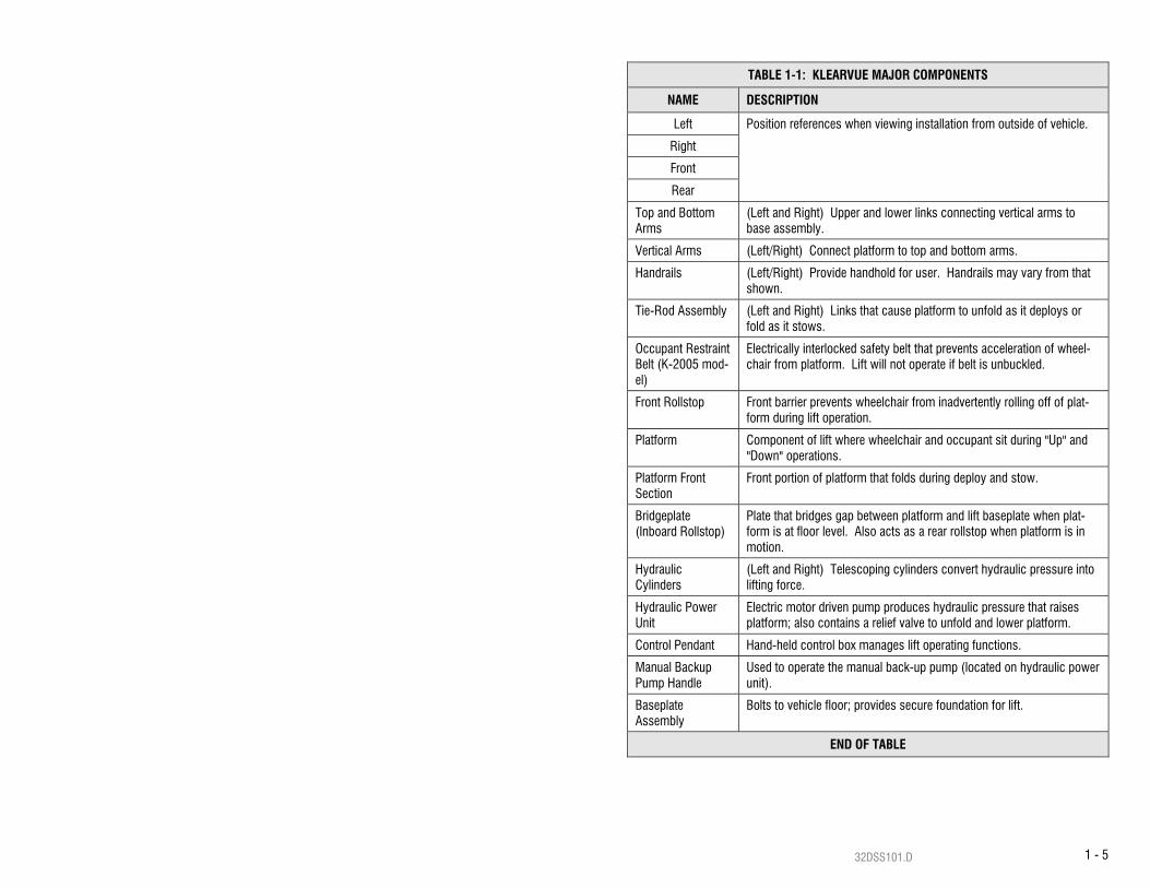
E. MAJOR COMPONENTS The major components of the K-Series® KlearVue lift are in Figure 1-1. A description of each of the components is in Table 1-1.
CO
NTR
OL PE
ND
ANT
LEFT
RIG
HT
TOP
AN
D B
OTTO
M A
RM
S
RE
AR
BAS
EPLATE
ASS
EMBLY
MA
NU
AL BA
CKU
P
PO
WE
R U
NIT
HY
DR
AU
LIC
BR
IDG
EPLA
TE
FRO
NT
FRO
NT
FRO
NT
PLA
TFOR
M
HA
ND
RA
IL
VER
TICA
L AR
M
PLA
TFOR
M S
EC
TION
PU
MP H
AN
DLE
CY
LIND
ER
HY
DR
AU
LIC
RO
LLSTO
P
PLA
TFOR
M SE
CTIO
NR
EAR
FOLD
ING
LINKA
GE
PLA
TFOR
MH
ING
ES
FIGURE 1-1: K-SERIES MAJOR COM
PONENTS
1 - 532DSS101.D
TABLE 1-1: KLEARVUE MAJOR COMPONENTS
NAME DESCRIPTION
Left Position references when viewing installation from outside of vehicle.
Right
Front
Rear
Top and Bottom Arms
(Left and Right) Upper and lower links connecting vertical arms to base assembly.
Vertical Arms (Left/Right) Connect platform to top and bottom arms.
Handrails (Left/Right) Provide handhold for user. Handrails may vary from that shown.
Tie-Rod Assembly (Left and Right) Links that cause platform to unfold as it deploys or fold as it stows.
Occupant Restraint Belt (K-2005 mod-el)
Electrically interlocked safety belt that prevents acceleration of wheel-chair from platform. Lift will not operate if belt is unbuckled.
Front Rollstop Front barrier prevents wheelchair from inadvertently rolling off of plat-form during lift operation.
Platform Component of lift where wheelchair and occupant sit during "Up" and "Down" operations.
Platform Front Section
Front portion of platform that folds during deploy and stow.
Bridgeplate (Inboard Rollstop)
Plate that bridges gap between platform and lift baseplate when plat-form is at floor level. Also acts as a rear rollstop when platform is in motion.
Hydraulic Cylinders
(Left and Right) Telescoping cylinders convert hydraulic pressure into lifting force.
Hydraulic Power Unit
Electric motor driven pump produces hydraulic pressure that raises platform; also contains a relief valve to unfold and lower platform.
Control Pendant Hand-held control box manages lift operating functions.
Manual Backup Pump Handle
Used to operate the manual back-up pump (located on hydraulic power unit).
Baseplate Assembly
Bolts to vehicle floor; provides secure foundation for lift.
END OF TABLE

1 - 6 32DSS101.D
This page intentionally left blank.

32DSS101.D 2 - 1
II. K-SERIES® LIFT OPERATING INSTRUCTIONS his chapter contains safety precautions, daily safety check instructions, control and indica-tor descriptions, and operating instructions for the RICON K-Series® KlearVue™ Wheelchair Lift. This chapter must be thoroughly understood by operator before using lift.
A. SAFETY PRECAUTIONS The following safety precautions must be complied with at all times when operating lift: Refer to Figure 2-1. Deploying lift when vehicle is on sloped ground is hazardous. Operate
lift with vehicle parked on level ground. Vehicle must be safely parked with parking brake ON before using lift.
Inspect lift before use. DO NOT use lift if any unsafe condition exists, or unusual noises or movements are noticed, and contact a Ricon dealer or qualified service technician for re-pair.
Read and comply with all warning labels and symbols affixed to wheelchair lift. Refer to Figure 2-2. Wheelchair occupant must face outward on platform when entering or
exiting vehicle. Due to variations in the size and configuration of mobility aids, for maxi-mum safety, Ricon requires that passengers always face outward when riding the lift plat-form.
It is never safe for a wheelchair occupant to exit a vehicle facing inboard. It is not safe to rely on a threshold warning device (audible or other) to confirm that it is safe to exit vehicle while facing inboard. Exiting the vehicle while facing outboard allows for visual confirma-tion that the lift platform has been raised in the event that the threshold warning device is inoperative or unheard and prevents the occupant from exiting the vehicle backwards when the platform is still on the ground.
When exiting vehicle, verify that platform is at same height as floor and front rollstop is up and locked.
T
FIGURE 2-1: SLOPED PARKING HAZARD
FIGURE 2-2: ALWAYS FACE OUTBOARD WHEN RIDING ON THE LIFT PLATFORM

32DSS101.D 2 - 2
Do not place equipment or furniture inside vehicle that may prevent pivoting of your wheel-chair. Being able to pivot assures that you can safely exit facing outward.
The outer rollstop is intended to prevent slow, or unintentional, rolling off the platform. The outer rollstop is not designed to stop a quick moving wheelchair. The wheelchair might tip and possibly injure its occupant if the small front wheels collide hard with the rollstop. The large rear wheels of a quick moving wheelchair can also roll over the rollstop. Use great care, board platform slowly, and lock wheelchair brakes.
Be certain wheelchair fits safely on platform; it must not extend beyond edges or interfere with operation of rollstop.
Do not operate with a load in excess of 800 lbs (364 kg). Keep arms, legs, and clothing away from moving lift parts. The lift is intended for ONE wheelchair and its occupant. Do not overload lift. Refer to Figure 2-3. Keep others clear while operating lift.
Do not allow an untrained person to operate lift. Careful supervision is necessary if used by or near children. Do not allow anyone to stand on bridgeplate. A bent bridgeplate can interfere with the plat-
form as it raises and lowers. LOCK WHEELCHAIR BRAKES before moving platform (power chair users should turn off
power and set brake). Use great care in wet conditions, because the wheelchair brakes are less effective if wheels
or platform are wet. Never leave platform outside of vehicle. Return lift to stowed position after use. Do not place a wheelchair on lift if it is too large for the vehicle. The wheelchair must be able
to pivot freely inside vehicle to comply with lift instructions for entering and exiting vehicle. Read and understand these safety precautions. Review them periodically and ask any at-
tendants or other operators to read them as well. Contact a Ricon dealer or Ricon Product Support if there are questions.
B. DAILY SAFETY CHECK Inspect lift before use and meet the following conditions: All functions operate properly. DO NOT use lift if unusual noises or movements exist, and
contact a Ricon dealer or qualified service technician for repair. Vehicle interlock is operating properly. No objects that may interfere with operation are present. General appearance and lubrication are satisfactory and all fasteners are tight.
FIGURE 2-3: STAND CLEAR OF PLATFORM

32DSS101.D 2 - 3
C. LIFT FUNCTIONS
TABLE 2-1: LIFT FUNCTIONS
FUNCTION DESCRIPTION
DEPLOY
Platform unfolds and deploys from stowed position. (the doors will automatically open before lift deploys if vehicle is equipped with a power door operator).
DOWN Platform lowers from floor level to ground level. (rollstop lowers
automatically when platform contacts ground).
UP Platform raises from ground level to floor level. (rollstop raises
automatically when platform leaves ground).
STOW
Platform folds and stows from floor level. (the doors will auto-matically close after lift is stowed if vehicle is equipped with a power door operator).
END OF TABLE
NOTE: The up and down functions do not operate when platform is stowed.
POSITIONSTOWED
NOTE:
LEVELGROUND
POINT SHIELDS REMOVED
LEVELFLOORVEHICLE
ARMRESTS AND PINCH
FOR CLARITY.
FIGURE 2-4: PLATFORM POSITIONS

32DSS101.D 2 - 4
D. CONTROLS AND INDICATORS
WARNING
THE LIFT CAN OPERATE ONLY WHEN PERMITTED TO BY THE VEHICLE INTERLOCK CIRCUITRY. DO NOT OPERATE LIFT WITH INTERLOCK BYPASSED. REFER TO VEHICLE OWNER/OPERATOR MANUAL FOR INTERLOCK INSTRUCTIONS BEFORE OPERATING LIFT.
Control Pendant Refer to Figure 2-5. The lift is operated with two rocker buttons located on a hand-held, hard-wired remote-control pendant. Each lift function is controlled by pushing one end of the appro-priate button. Pushing the DEPLOY button unfolds platform from vehicle, and pushing the STOW button folds platform into vehicle. Pushing the DOWN button lowers platform towards ground, and pushing the UP button raises platform towards floor. Buttons must be held depressed until function completes. The pendant is stowed on a wall-clip inside vehicle.
FIGURE 2-5: LIFT CONTROL PENDANT

32DSS101.D 2 - 5
Interlock Indicator Light Refer to Figure 2-6. The vehicle interlock system prevents operation of lift when it is unsafe. The interlock indicator light reveals whether interlock is operating properly, if an interlock system is interfaced with lift. The light stays illuminated at all times if there is no interlock system in-stalled. The indicator light illuminates when the interlock system provides electrical power to lift, and is off when power is removed. Circuit Breaker for Optional Door Operator
Refer to Figure 2-6. The circuit breaker for optional door operator is mounted on hydraulic pump assembly. The circuit breaker button pops up when there is a short circuit in door opera-tor. DO NOT hold button pressed if pressing and releasing button does not restore power. Con-tact a Ricon dealer or qualified service technician for repair. Refer to appropriate Ricon Power Door Operator Service Manual for a detailed description. Control System Circuit Breaker
Refer to Figure 2-6. The Control System Circuit Breaker is mounted on hydraulic pump assem-bly. The circuit breaker button pops up when there is a short circuit in the control system. DO NOT hold button pressed if pressing and releasing button does not restore power. Contact a Ri-con dealer or qualified service technician for repair. Pump Solenoid LED Status Indicator
Refer to Figure 2-6. A second pump solenoid is installed next to the original pump solenoid and a LED is located between the 8A and 30A circuit breakers. The LED monitors the condition of the two solenoids. The LED is normally green when the pump is operating and off when the pump is off. For more information on this LED refer to the service manual 32DSSP02.
FIGURE 2-6: INDICATOR LIGHT/ CIRCUIT BREAKERS
CIRCUIT BREAKER8 AMP CONTROL SYSTEM
30 AMP DOOR OPERATOR
INDICATOR LIGHTINTERLOCK
CIRCUIT BREAKERPUMP SOLENOIDS
LED STATUS INDICATOROR

32DSS101.D 2 - 6
Main Circuit Breaker Refer to Figure 2-7. The main circuit breaker, located in en-gine compartment, interrupts electrical power to the lift elec-trical system when a short circuit occurs. The circuit breaker reset tab is shown in the normal, or reset, position. The circuit breaker reset tab flips down when a short circuit occurs. DO NOT hold button pressed if pressing and releasing button does not restore power. Contact a Ricon dealer or qualified service technician for repair.
Manual Backup Pump
Refer to Figure 2-8. The manual backup pump raises the platform when electrical power is not functional. Controls for the pump consist of a handle for raising platform, and a release valve for lowering it. Instructions for operating the manual pump are in the MANUAL OPERATION para-graph of the LIFT OPERATION section in this chapter.
FIGURE 2-7: MAIN CIRCUIT BREAKER
FIGURE 2-8: MANUAL BACKUP PUMP & HANDLE

32DSS101.D 2 - 7
E. LIFT OPERATION
WARNING
IMPROPER USE OF LIFT CAN RESULT IN PERSONAL INJURY. USERS MUST READ AND FOLLOW OPERATING INSTRUCTIONS IN OPERATOR MANUAL. ADDITIONAL COPIES OF OPERATOR MANUAL ARE AVAILABLE FROM:
RICON CORPORATION 7900 NELSON ROAD
PANORAMA CITY, CA 91402 (800) 322-2884 OR (818) 267-3000
DO NOT EXCEED RATED LOAD CAPACITY OF 800 POUNDS (364 KG).
PRIOR TO USE, INSPECT WHEELCHAIR LIFT FOR PROPER FUNCTION, REQUIRED MAINTENANCE, AND DAMAGE. IF A PROBLEM EXISTS, DO NOT USE LIFT AND CONTACT A RICON DEALER OR QUALIFIED SERVICE TECHNICIAN FOR REPAIR.
THIS LIFT IS DESIGNED FOR USE BY WHEELCHAIR OCCUPANTS ONLY.
RICON CORPORATION DISCLAIMS LIABILITY FOR DAMAGE OR PERSONAL INJURY RESULTING FROM MODIFICATION TO LIFT, LACK OF MAINTENANCE OR REPAIR, NEGLIGENCE, ABUSE, OR FAILURE TO FOLLOW LIFT OPERATING INSTRUCTIONS.
Be certain vehicle is safely parked on a level area away from traffic before operating lift. Allow space for lift operation and passenger boarding.
The lift operator must take special care to be certain that area is clear before deploying lift. Be certain there are no obstacles beneath platform.
Open doors manually if vehicle is not equipped with a Power Door Operator. The vehicle door(s) will open automatically before platform deploys and close after platform is stowed, if vehicle is equipped with a Power Door Operator.
Engage the vehicle safety interlock system (e.g. transmission, parking brake, etc), if so equipped, before operating lift. The lift will not operate until this is accomplished.
WARNING
ATTENDANT SHOULD ALWAYS REMAIN NEAR PASSENGER TO RENDER IMMEDIATE ASSISTANCE, IF NECESSARY. KEEP OTHERS CLEAR WHEN OPERATING LIFT. MAINTAIN PRESSURE ON BUTTON UNTIL FUNCTION COMPLETES. BE CERTAIN WHEELCHAIR FITS PROPERLY ON PLATFORM AND DOES NOT CONTACT ROLLSTOP, PREVENTING IT FROM LOCKING AS PLATFORM RAISES.

32DSS101.D 2 - 8
1. ENTERING VEHICLE: a. DEPLOY PLATFORM - Push and hold DEPLOY button until platform unfolds complete-
ly from vehicle and stops at floor level.
WARNING
DO NOT STAND ON BRIDGEPLATE (INBOARD ROLLSTOP) AS PLATFORM LOWERS. PUSH AND HOLD DOWN BUTTON UNTIL PLATFORM SETTLES AT GROUND LEVEL. CAREFULLY EXIT PLATFORM.
b. LOWER PLATFORM - DO NOT STAND on inboard rollstop as platform lowers. Push and hold DOWN switch until lift contacts ground and rollstop opens completely. 1) Carefully place wheelchair in center of platform, facing outward away from ve-
hicle, and LOCK WHEELCHAIR BRAKES. 2) Be certain wheelchair is safely within platform perimeter and will not interfere
with operation of front platform rollstop. c. RAISE PLATFORM - Push and hold UP button until platform raises and stops at ve-
hicle floor level. Rollstop must raise when platform leaves ground. 1) Release wheelchair brakes, carefully board passenger into vehicle, and secure
wheelchair. d. Refer to “Stowing Platform” section to stow platform.
2. EXITING VEHICLE: a. DEPLOY PLATFORM - Push and hold DEPLOY button until platform completely un-
folds from vehicle and stops at floor level. 1) Be certain platform is safely at vehicle floor level, front platform rollstop is in an
up and locked position and bridgeplate is resting on baseplate. 2) Carefully place wheelchair in center of platform, facing outward away from ve-
hicle, and LOCK WHEELCHAIR BRAKES. b. LOWER PLATFORM – DO NOT STAND on inboard rollstop as platform lowers. Push
and hold DOWN button until platform settles at ground level. Carefully exit platform. c. RAISE PLATFORM – Push and hold UP switch until platform rises to vehicle floor
level.
WARNING
DO NOT STAND ON BRIDGEPLATE (INBOARD ROLLSTOP) AS PLATFORM LOWERS.
32DSS101.D 2 - 9
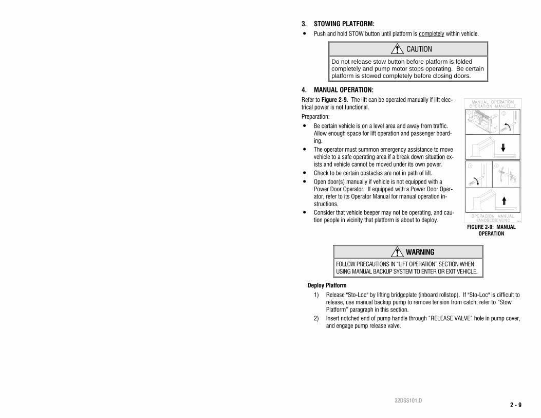
3. STOWING PLATFORM: Push and hold STOW button until platform is completely within vehicle.
CAUTION
Do not release stow button before platform is folded completely and pump motor stops operating. Be certain platform is stowed completely before closing doors.
4. MANUAL OPERATION: Refer to Figure 2-9. The lift can be operated manually if lift elec-trical power is not functional.
Preparation:
Be certain vehicle is on a level area and away from traffic. Allow enough space for lift operation and passenger board-ing.
The operator must summon emergency assistance to move vehicle to a safe operating area if a break down situation ex-ists and vehicle cannot be moved under its own power.
Check to be certain obstacles are not in path of lift. Open door(s) manually if vehicle is not equipped with a
Power Door Operator. If equipped with a Power Door Oper-ator, refer to its Operator Manual for manual operation in-structions.
Consider that vehicle beeper may not be operating, and cau-tion people in vicinity that platform is about to deploy.
WARNING
FOLLOW PRECAUTIONS IN “LIFT OPERATION” SECTION WHEN USING MANUAL BACKUP SYSTEM TO ENTER OR EXIT VEHICLE.
Deploy Platform
1) Release "Sto-Loc" by lifting bridgeplate (inboard rollstop). If "Sto-Loc" is difficult to release, use manual backup pump to remove tension from catch; refer to “Stow Platform” paragraph in this section.
2) Insert notched end of pump handle through “RELEASE VALVE” hole in pump cover, and engage pump release valve.
FIGURE 2-9: MANUAL OPERATION
32DSS101.D 2 - 10
CAUTION
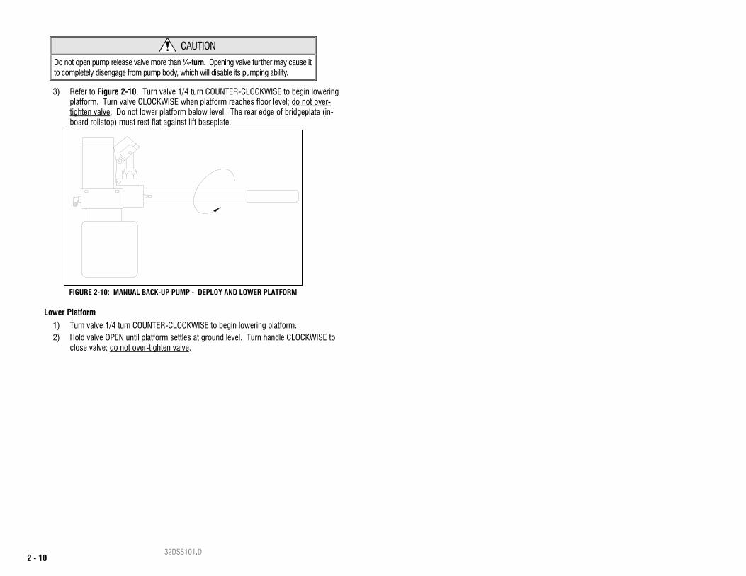
Do not open pump release valve more than ¼-turn. Opening valve further may cause it to completely disengage from pump body, which will disable its pumping ability.
3) Refer to Figure 2-10. Turn valve 1/4 turn COUNTER-CLOCKWISE to begin lowering platform. Turn valve CLOCKWISE when platform reaches floor level; do not over-tighten valve. Do not lower platform below level. The rear edge of bridgeplate (in-board rollstop) must rest flat against lift baseplate.
Lower Platform
1) Turn valve 1/4 turn COUNTER-CLOCKWISE to begin lowering platform. 2) Hold valve OPEN until platform settles at ground level. Turn handle CLOCKWISE to
close valve; do not over-tighten valve.
FIGURE 2-10: MANUAL BACK-UP PUMP - DEPLOY AND LOWER PLATFORM
32DSS101.D 2 - 11
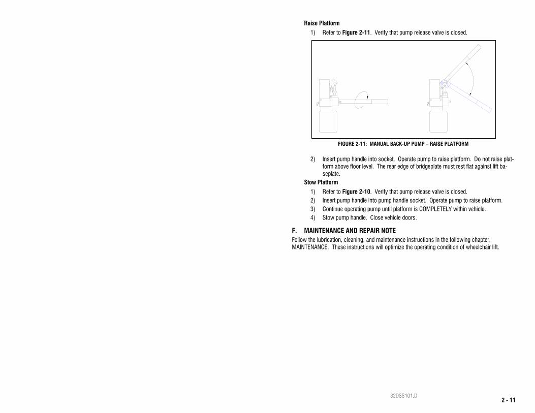
Raise Platform
1) Refer to Figure 2-11. Verify that pump release valve is closed.
2) Insert pump handle into socket. Operate pump to raise platform. Do not raise plat-form above floor level. The rear edge of bridgeplate must rest flat against lift ba-seplate.
Stow Platform
1) Refer to Figure 2-10. Verify that pump release valve is closed. 2) Insert pump handle into pump handle socket. Operate pump to raise platform. 3) Continue operating pump until platform is COMPLETELY within vehicle. 4) Stow pump handle. Close vehicle doors.
F. MAINTENANCE AND REPAIR NOTE Follow the lubrication, cleaning, and maintenance instructions in the following chapter, MAINTENANCE. These instructions will optimize the operating condition of wheelchair lift.
FIGURE 2-11: MANUAL BACK-UP PUMP – RAISE PLATFORM

32DSS101.D 2 - 12
This page intentionally left blank.
32DSS101.D 3 - 1
III. K-SERIES® MAINTENANCE egular maintenance of the Ricon K-Series® KlearVue™ Lift will optimize its performance and minimize the need for repairs. This chapter contains lubrication and cleaning instructions,
plus a maintenance schedule.
A. MAINTENANCE INFORMATION Additional maintenance information is available in the K-Series Service manual, part number 32DSS102. This manual is available from Ricon in printed hard copy, or at the Ricon website in PDF format. The website is located at www.riconcorp.com. Click on RICON CORPORA-TION and then DEALER’S ROOM at the website. Entry to the dealer’s room will require a Dealer Number and a Password.
CAUTION
THIS RICON PRODUCT IS HIGHLY SPECIALIZED. MAINTENANCE AND REPAIRS MUST BE PERFORMED BY A RICON DEALER OR QUALIFIED SERVICE TECHNI-CIAN USING RICON REPLACEMENT PARTS.
B. CLEANING
Regular cleaning of lift with mild soap and water (i.e. liquid dish soap or car wash liquid) and drying thoroughly will protect painted surfaces. Cleaning is especially important in areas where roadsalt is applied in winter. Make sure lift pivot points remain clear and clean prior to lubrication.
C. LUBRICATION
CAUTION
Do not lubricate electric motor or other electrical compo-nents. Oil attracts debris, which may cause a short circuit.
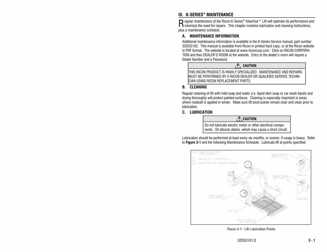
Lubrication should be performed at least every six months, or sooner, if usage is heavy. Refer to Figure 3-1 and the following Maintenance Schedule. Lubricate lift at points specified.
R
Figure 3-1: Lift Lubrication Points

32DSS101.D 3 - 2
D. MAINTENANCE SCHEDULE
Under normal operating conditions, maintenance inspections are required at least every six months (1750 cycles), and a thorough inspection should be performed at the intervals in Table 3-1. Service should be increased under conditions of heavy use (more than 10 cycles per day.)
TABLE 3-1: MAINTENANCE SCHEDULE
SERVICE POINT ACTION TO PERFORM
DAILY SAFETY CHECK
Overall Condition Listen for abnormal noises as lift operates (i.e. grinding or binding nois-es.)
Control Pendant Verify that control pendant is undamaged and cable connectors are tight.
TWO WEEK SAFETY CHECK
Overall Condition Listen for abnormal noises as lift operates (i.e. grinding or binding noises.)
Inspect underside of vehicle for anything that is out of place.
Control Pendant Verify that control pendant is undamaged and cable connectors are tight.
Electrical Wiring Inspect electrical wiring for frayed wires, loose connectors, etc.
Vehicle Interlock Place vehicle in NON-INTERLOCK mode and attempt to operate lift.
Decals Verify that lift decals are properly affixed, clearly visible, and legible. Re-place, if necessary.
Handrails Verify that handrail fasteners are properly tightened.
Lift Mounting Points
Verify that vehicle mounting and support points are undamaged.
Verify that mounting bolts are sufficiently tight.
Main Lifting Pivots
Verify that arm pins are properly installed, free from damage, and locked in position.
Platform Pivot Points
Verify that platform moves freely, without binding, and does not wobble.
Bridgeplate (Inner rollstop)
Verify that bridgeplate operates without binding during lift functions. Verify that bridgeplate deploys fully when platform stops at floor lev-
el. Verify bridgeplate rests flat against baseplate.
Front Rollstop Verify that rollstop opens completely when platform contacts ground. Verify that rollstop closes and locks when platform leaves ground.

32DSS101.D 3 - 3
TABLE 3-1: MAINTENANCE SCHEDULE
SERVICE POINT ACTION TO PERFORM
Hydraulic Power Unit
CAUTION Check and add fluid when platform is at GROUND level. Fluid added when lift is raised will overflow when platform is lowered.
Verify that pump hydraulic fluid level is at FULL mark when platform is at ground level. Add Texaco 01554 Aircraft Hydraulic Oil or equiv-alent U.S. mil spec H5606G fluid.
Verify there are no hydraulic fluid leaks. Verify that manual release valve is closed.
SIX MONTH SAFETY CHECK (or 1750 cycles of operation)
Handrails Verify that all handrail fasteners are properly tightened.
Cleaning and Lubrication
1. Clean lift with mild soap and water and wipe dry. Prevent rust by coating all surfaces with a light oil. Remove excess oil.
2. Spray penetrating oil (Curtisol® Red Grease 88167 or WD-40®) where specified in Figure 3-1, following directions on container. Remove excess grease from surrounding areas.
CAUTION
The annual safety check must be performed by a Ricon dealer or qualified service technician.
ANNUAL SAFETY CHECK (or 3500 cycles of operation)
Hydraulic Cy-linder, Hoses and Fittings
Check hydraulic cylinder for evidence of leaks. Inspect hydraulic hoses for damage. Verify that all fittings are tight.
END OF TABLE

32DSS101.D 3 - 4
E. K-SERIES DECALS Refer to Figure 3-2 for the location and part numbers of lift decals. Check decals for chipping, peeling, fading, and illegibility. Check decals at intervals listed in Table 3-1, and replace as ne-cessary. The decals must be located and orientated as shown. Note that part number for serial number decal is not provided, because it must be replaced by Ricon.
Figure 3-2: Decal Locations and Part Numbers
BEI UNUNTERBROCHENERWARNLICHT ANZEIGE ISTWARTUNG ERFORDERLICH
MANTENIMIENTO ESREQUERIDO SI PERMANECE
CONTINUAMENTE ILUMINADO
MAINTENANCE REQUIRED IFCONTINUOUSLY ILLUMINATED
MAINTENANCE DOIT ETREFAITE SI CETTE LUMIERE
RESTE ALLUMEE ENPERMANENCE