k SERIES CATALOG rev 1 01 - World's Leading Supplier of Side … · 2018-03-22 · coupled to the...
84
TS Twin impeller single stage MS Single impeller single stage MD Single impeller double stage TD Twin impeller double stage DESIGNS designs “GO R ” “GVR ” Design Design Standard Design The standard FPZ design is a direct drive configuration, with a dynamically balanced impeller fitted directly on the motor shaft. Fi t motors are 2-pole, 1 or 3 phase, rated for continuous service. Standard motors utilize class F insulation, are suitable for use with a variable speed drive (3 phase only), and are tropicalized for corrosion resistance. S le or two stage options are pictured above. GOR / GVR Design “GOR / GVR” designs utilize a standard nema (or metric) electric motor that is directly coupled to the blower shaft. This direct coupled design allows the use of specialty motors that may be required to meet a variety of electrical requirements. For some models the vacuum / pressure capabilities can be increased with this GOR / GVR design (pictured right). FPZ, Inc. 150 N. Progress Drive Saukville, WI 53080 USA Tel. (262) 268-0180 [email protected] www.fpz.com ing ed t
Transcript of k SERIES CATALOG rev 1 01 - World's Leading Supplier of Side … · 2018-03-22 · coupled to the...

TSTwin impeller single stage
MSSingle impeller single stage
MDSingle impeller double stage
TDTwin impeller double stage
DESIGNSdesigns
“GO R” “GVR ” Design Design
Standard Design
The standard FPZ design is a direct drive configuration, with a dynamically balanced impeller fitted directly on the motor shaft. Fi t motors are 2-pole, 1 or 3 phase, rated for continuous service. Standard motors utilize class F insulation, are suitable for use with a variable speed drive (3 phase only), and are tropicalized for corrosion resistance. S le or two stage options are pictured above.
GOR / GVR Design “GOR / GVR” designs utilize a standard nema (or metric) electric motor that is directly coupled to the blower shaft. This direct coupled design allows the use of specialty motors that may be required to meet a variety of electrical requirements. For some models the vacuum / pressure capabilities can be increased with this GOR / GVR design (pictured right).
FPZ , In c . 1 50 N . Pr ogr es s Dr ive Sa uk v i l l e , WI 5308 0 USA Tel . (262 ) 26 8-01 80 usa@ fpz .c o m www.fp z .c om
ing
edt

FPZ , In c . 1 50 N . Pr ogr es s Dr ive Sa uk v i l l e , WI 5308 0 USA Tel . (262 ) 26 8-01 80 usa@ fpz .c o m www.fp z .c om
applicationsAPPLICATIONS
Thousands of FPZ blowers are working in a variety of
applications: from commercial to industrial installations,
in food processing to pharmaceuticals, from textiles to
aerospace, in medical applications to environmental.
Wherever efficiency and reliability are needed, FPZ
responds with the appropriate product “solution”
- Compact execution- Simple concept- Reduced maintenance costs- Modular design
Advantages of side channel blowers
- Pulsation and oil free air
Blowers h ave an impeller blade m ounted inside a housing. As air passes the inlet port, impellerblades draw air in and accelerate the air outwardand forward. As each im eller blade strikes it,the air m oves faster a n d faster. At the base of the hous ing an air stripper diverts the air out ofthe hou s ing redu cing the s peed and the nincreasing .
How Blowe
the pressure
rs Work
p

Table of Contents SS1705 r
Page(s)General Pressure and Vacuum Performance Curves 4 5
K Series "MOR" Blowers - Direct Drive Max CFM
Max Pressure (In H2O)
Max Vacuum (In Hg.) Pressure Vacuum
SCL K03-K06 MS Single Stage Blowers 216 122 8.9 6-7 38-39SCL K07-K12 MS Single Stage Blowers 726 201 10.3 8-9 40-41SCL K05-K06 TS Single Stage Blowers 400 85 6.3 10-11 42-43SCL K07-K12 TS Single Stage Blowers 1410 100 8.1 12-13 44-45SCL K07R-12 MD Two Stage Blowers 336 290 14.0 14-15 46-47SCL K05-K06 TD Two Stage Blowers 222 180 11.8 16-17 48-49SCL K07-K12 TD Two Stage Blowers 716 220 14.0 18-19 50-51
06 / R Series Performance DataSCL 06 Single Stage Blowers 39 52 3.5 20-21 52-53SCL 10DL-15DH Two Stage Blowers 35 120.5 8.1 22-23 54-55SCL R20-R40 MD Two Stage Blowers 81 201 11.1 24-25 56-57K Series Direct Coupled - "GOR/GVR" configurationSCL K03-K06 MS-GOR/GVR Single Stage Blowers 216 140 9.6 26-27 58-59SCL K07-K12 MS-GOR/GVR Single Stage Blowers 726 200 10.3 28-29 60-61SCL K05-K06 TS-GOR/GVR Single Stage Blowers 400 130 7.8 30-31 62-63SCL K07-K12 TS-GOR/GVR Single Stage Blowers 1410 150 10.3 32-33 64-45SCL K07R- K12 MD GOR/GVR Two Stage Blowers 336 280 14.7 34-35 66-67SCL K07-K12 TD GOR/GVR Two Stage Blowers 716 225 13.2 36-37 68-69Values in above table based on 60 hz performance
AccessoriesInstallation Guide General guide on how to install accessories. 70VG / PG / CV / SS / IH Gauges, Check Valves, Silencers, and Sound Enclosures 71VRL6-9 Safety valve selection guide 72VRL6-9 Safety Valves 73CSL / CT Filters for vacuum applications. 74
FS Filters & dirty filter indicator for pressure applications 75
VK / PK Flange Connectors for safety valves and flexible hoses 76
VS 6 / VS 8 Flow Converting Devices for diverting air stream 77CA / CK Filter Manifolds and 90 Degree Manifold for K series blowers 78MF / TF / MP Flexible Sleeves, Flanges, Sleeves 79
Technical80
8182838485
Altitude chart and coversion factorsSingle Phase Motor informationThree Phase Motor Information575 V Premium Efficiency Three Phase Motor InformationAirflow Through an OrificeFPZ Pneumatic Range
DisclaimerThe information contained in this catalog is based on information that we believe to be correct. It is the users responsibility to determine the suitability of the product for the application they are used in and the user assumes all risk and liability whatsoever in connection therewith.

FPZ , In c . 1 50 N . Pr ogr es s Dr ive Sa uk v i l l e , WI 5308 0 USA Tel . (262 ) 26 8-01 80 usa@ fpz .c o m www.fp z .c om
Pressure Performance Curves
K07-MS K08-MS
K10-MS
K07-TS
K08-TS
K10-TS
K09-MS
K09-TS
K11-TS
K05-TS
K06-TS
16001200 14001000900800700600500400350300250 200 150 100 75 50 25 0
0
20
40
60
80
100
120
140
160
180
200
220
Capacity (cfm)
Stat
ic d
iffer
entia
l pre
ssur
e ( I
n W
G)
K05-MS
K06-MS
K03-MS
K04-MS
06
Legend
K10-TS
Model
K08-MD
K10-MD
K07-TD
K08-TD
K10-TD
K09-MD
K09-TD
K11-TD
700650600550500450400 350300250200175150 125 100 75 50 25 800
0
20
40
60
80
100
120
140
160
180
200
220
240
260
280
300
320
0
Stat
ic d
iffer
entia
l pre
ssur
e ( I
n W
G)
K07-MD
Legend
K10-TD
Model
Curves refer to air at 68°F temperature and 29.92 In Hg atmospheric pressure (abs) measured at inlet port. Tolerance on given values ± 10% - data can change without prior notice.
Capacity (cfm)
K11-MS
K12-MS
K11-MD
K12-MD
K12-TS
K12-TD
4
R20-MD
15DH
10DL
K05-TD
R30MD
R40MD
K06-TD

FPZ , In c . 1 50 N . Pr ogr es s Dr ive Sa uk v i l l e , WI 5308 0 USA Tel . (262 ) 26 8-01 80 usa@ fpz .c o m www.fp z .c om
Vacuum Performance Curves
K05-MS
K06-MS
K07-MS
K08-MS
K09-MS
K10-MS
K05-TS
K06-TS
K07-TS
600 1100800450 1000900700500400350300250 200 150 100 75 50 25 0 1200 1400 1600
K09-TS
K10-TS
K11-TS
06
0
20
40
60
80
100
120
140
160
Capacity (cfm)
Stat
ic d
iffer
entia
l pre
ssur
e ( I
n W
G)
Capacity (cfm)
Stat
ic di
ffer
entia
l pre
ssur
e ( I
n W
G)
K07-MD
K08-MD
K09-MD
K10-MD
K05-TD
K06-TD
K07-TD
K08-TD K09-TD
K10-TD
550 800650450 750700600500400 350300250200150 100 75 50 25 0
10DL
15DH
0
20
40
60
80
100
120
140
160
180
200
220
Curves refer to air at 68° F temperature, measured at inlet port and 29.92 In Hg atmospheric backpressure (abs).Tolerance on given values ± 10% - data can change without prior notice.
K11-MD
K12-MD
K11-MS
K12-MS
Legend
odelM
TSK10-
Legend
Model
K12-TS
K11-TD
K1 -TD2
K03-MS
5
R20-MD
K04-MS
K08-TS
R40MD
R30MD
K10-TD
sschultz
Line
sschultz
Line

FPZ , In c . 1 50 N . Pr ogr es s Dr ive Sa uk v i l l e , WI 5308 0 USA Tel . (262 ) 26 8-01 80 usa@ fpz .c o m www.fp z .c om
TECHNICAL CHARACTERISTICS - Aluminium alloy construction - Smooth operation - High efficiency impeller - Maintenance free - Mountable in any position - Recognized TEFC - cURus motor
OPTIONS - Special voltages (IEC 38) - Surface treatments
ACCESSORIES - Inlet and/or inline filters - Additional inlet/outlet silencers - Safety valves - Flow converting device - Optional connectors
Model Maximum
flow Scfm
Installed power
Hp
Maximum differential pressure
p ( In WG )
Noise level Lp dB (A)
(1)
Overall dimensions
H Weight
60 Hz 50 Hz 60 Hz 50 Hz 60 Hz 50 Hz 60 Hz 50 Hz 3500 rpm 2900 rpm 3500 rpm 2900 rpm 3500 rpm 2900 rpm 3500 rpm 2900 rpm Inches Lbs
3/4 3/4 64 60 62.0 60.0 10.43 K03-MS 52 43
1 95 62.3 60.3 1 1 ½ 1 ½ 11.65 40.3
2 2 85 100 65.0 63.0 13.78 48.0 K04-MS 98 81 3 - 120 - 65.2 - 13.78 52.5 2 2 52 70 70.5 68.5 13.20 56.7 3 3 80 110 70.8 68.8 13.20 60.6 K05-MS 156 129
4 4 12 120 71.1 69.1 14.40 77.2 3 3 40 65 73.0 71.0 13.80 69.0 4 4 64 95 73.3 71.3 14.17
5 ½ 5 ½ 130 73.6 71.6 15.5 K06-MS 216 179
6 1/5 - 122 - 73.9 - 1
(1) Noise measured at 1 m distance with inlet and outlet ports piped, in accordance to ISO 3744.
Model a b c d e f G I m n o p1 q r s t u z
K03-MS 9.49 10.55 5.79 1.69 9.06 8.07 1”1/4 NPT 3.39 0.39 3.27 5.59 8.07 0.71 2.95 0.16 M6 5.51 0.47 K04-MS 11.22 12.40 6.77 1.93 10.04 8.86 1” 1/2
K05-MS K06-MS 14.80
e
a
fIG
d
c
b
s
p1
o
Ømn r q
z
H
3x120°øu
t
Accessory
SCL K03 / K04 / K05 / K06
SN 1874-
- For proper use, the blower should be equipped with inlet filter and safety valve; other accessories available on request. - Ambient temperature from +5° to +104°F. - Specifications subject to change without notice.
Dimensions in inches. Dimension for reference only.
MS SERIES
12.87 12.60 10.24 2” NPT .59 .16 8 .87 .75 0 M 7 0 0 4. 27 15.47 8.07 2.13 12.80 11.42 2” NPT . 14.37
NPT 4.02 0.47 3.74 6.73 8.74 0.71 2.76 0.16 M6 6.89 0.71
4.92 0.59 5.51 10.71 13.15 0.71 3.35 0.16 M8 9.45 0.75 10 .43 12.60 0 .71 .4 53 3.86
REGENERATIVE BLOWERS - PRESSURE
58 80 64.8 62.8
0
110
1
24.3
82.5
85.3
2.0 32.0
®
2.13.8 7 7
1 72
2B 1/2
95.56.3
6

FPZ , In c . 1 50 N . Pr ogr es s Dr ive Sa uk v i l l e , WI 5308 0 USA Tel . (262 ) 26 8-01 80 usa@ fpz .c o m www.fp z .c om
CAPA
CITY
A
BSO
RBED
PO
WER
TE
MPE
RATU
RE IN
CREA
SE
SCL K03 / K04 / K05 / K06
SN 1874-1 B 2/2
Curves refer to air at 68°F temperature and 29.92 In Hg
Data subject to change without notice.
p
psig
0
1
2
3
4
5
0 50 100 150 200 250
4
K05-MS
3
2
0
20
40
60
80
100
120
140
In W
G
Scfm
60 Hz
6 1/5
5 1/2
4
K06-MS
3
3
2
1 1/2
K04-MS K03-MS
3/4
1
p
psig
0
1
2
3
4
5
0
20
40
60
80
100
140
0 1 2 3 4 5 6 7
K06-MS K05-MS
60 Hz
Hp
In W
G
K04-MS
K03-MS
0
1
2
3
4
5
p
psig
In W
G
0
20
40
60
80
100
120
140
160
0 50 100 150 200 Scfm
50 Hz
4
3
3
5 1/2
4
1 1/2
2
3/4
K03-MS K04-MS
2
K05-MS K06-MS
0
1
2
3
4
5
p
psig
In W
G
0
20
40
60
80
100
120
160
0 1 2 3 4 5 6
50 Hz
Hp
K05-MS
K06-MS
K04-MS
K03-MS
p
psig
0
1
2
3
4
5
K05-MS K04-MS
60 Hz
K06-MS
0
20
40
60
80
100
140
0 20 40 60 80 100 120 140 °F
In W
G
K03-MS
0
1
2
3
4
5
p
psig
0 20 40 60 80 100 120 140 160 180 200 °F
In W
G
0
20
40
60
80
100
120
16050 Hz
K05-MSK06-MS
K04-MS
K03-MS
MS SERIES
atmospheric pressure (abs) measured at inlet port.
REGENERATIVE BLOWERS - PRESSURE
Values for flow, power consumption and temperature rise: +/ 10% tolerance. -
®
2
7

FPZ , In c . 1 50 N . Pr ogr es s Dr ive Sa uk v i l l e , WI 5308 0 USA Tel . (262 ) 26 8-01 80 usa@ fpz .c o m www.fp z .c om
Model Maximum
flow Scfm
Installed power
Hp
Maximum differential pressure
p ( In WG )
Noise level Lp d B (A)
(1)
Overall dimensions
H Weight
60 Hz 50 Hz 60 Hz 50 Hz 60 Hz 50 Hz 60 Hz 50 Hz 3500 rpm 2900 rpm 3500 rpm 2900 rpm 3500 rpm 2900 rpm 3500 rpm 2900 rpm Inches Lbs
K07-MS 294 243
4 4 50 80 78.7 76.7 15.6 116.2 5 ½ 5 ½ 80 110 79.0 77.0 16. 3 119.07 ½ 7 ½ 121 141 79.3 77.3 18.4 160.5 10 10 171 - 79.6 77.6 19.1 172.6
K08-MS 381 316
5 ½ 5 ½ 40 70 79.7 77.7 16.3 124.87 ½ 7 ½ 70 100 80.0 78.0 18.4 166.5 10 10 111 141 80.3 78.3 19.1 179.0 15 15 171 171 80.6 78.6 19.1 192.0
K09-MS 471 390
7 ½ 7 ½ 50 80 80.2 78.2 18.8 186.3 10 10 80 120 80.5 78.5 19.5 199.0 15 15 141 171 81.0 79.0 19.6 212.020 20 171 - 81.3 79.3 22.0 245.0
K10 -MS 556 460
7 ½ 7 ½ 30 60 80.1 78.1 18.8 189.6 10 10 50 90 80.5 78.5 19.5 202.015 15 111 141 81.0 79.0 19.6 215.0 20 20 161 81.4 79.4 22.0 248.0 25 25 201 - 81.6
17179.6 24.0 322.0
K11 - MS 650 539
15 15 70 110 82.4 80.4 19.8 226.020 20 121 160 82.7 80.7 22.5 259.0 25 25 151 181 85.6 83.6 24.0 333.0
K12-MS 726 602 15 15 50 90 82.9 80.9 19.9 229.5
20 20 90 130 83.2 81.2 22.5 263.025 25 1 21 16 1 86.1 84.1 24.0 337.0
SCL K07 / K08 / K09 / K10 / K11 / K12 SERIES MS
SN 1805 1 1/2 - 7B
TECHNICAL CHARACTERISTICS - Aluminium alloy construction - Smooth operation - High efficiency impeller - Maintenance free - Mountable in any position - Recognized TEFC - cURus motor
OPTIONS - Special voltages (IEC 38) - Surface treatments
ACCESSORIES - Inlet and/or inline filters - Additional inlet/outlet silencers - Safety valves - Flow converting device - Optional connectors
Dimensions in inches. Dimension for reference only.
Model a b c d e f G I m n o p1 q r s t u z
K07-MS 16.69 18.84 10.59 3.23 18.43 17.24 3” NPT 6.10 0.51 11.81 13.78 20.16 0.98 5.39 0.20 M8 11.61 0.63 K08-MS 17.99 19.61 10.59 3.23 18.82 17.64 3” NPT 6.10 0.51 11.81 13.78 20.16 0.98 5.39 0.20 M8 12.2 0.63 K09-MS 19.37 22.09 12.40 3.78 20.00 18.82 4” NPT 7.17 0.51 11.81 13.78 23.07 0.98 7.83 0.20 M8 14.17 0.63 K1 MS 0- 20.31 22.56 12.40 3.78 20.00 18.82 4” NPT 7.17 0.51 11.81 13.78 23.07 0.98 7.83 0.20 M8 14.17 0.63 K11 MS - 21.34 23.74 13.07 3.58 21.26 20.00 4” NPT 7.87 0.51 11.81 13.78 23.46 0.98 8.03 0.20 M8 15.35 0.63 K1 -MS 2 21.57 23.82 13.07 3.58 21.26 20.00 4” NPT 7.87 0.51 11.81 13.78 23.58 0.98 8.03 0.20 M8 15.35 0.51
- For proper use, the blower should be equipped with inlet filter and safe . ty valve; other accessories available on request- Ambient temperature from +5° to +104°F. - Specifications subject to change without notice.
(1) Noise measured at 1 m distance with inlet and outlet ports piped, in accordance to ISO 3744.
Accessory
r q
p1 H
o
n
øm
3x120° øu
z
t
G
d
c b
e
f
I
a
s
8 REGENERATIVE BLOWERS - PRESSURE®

FPZ , In c . 1 50 N . Pr ogr es s Dr ive Sa uk v i l l e , WI 5308 0 USA Tel . (262 ) 26 8-01 80 usa@ fpz .c o m www.fp z .c om
Curves refer to air at 68°F temperature and 29.92 I . n Hg atmospheric pressure (abs) measured at inlet portValues for flow, power consumption and temperature rise: +/ 10% tolerance. -Data subject to change without notice.
ABS
ORB
ED P
OW
ER
TEM
PERA
TURE
IN
CREA
SE
SCL K07 / K08 / K09 / K10 / K11 / K12 MS SER IES
SN
180
/2
5-17B 2
0
1
2
3
4
5
6
7
8
p
psig
0
20
40
60
80
100
120
140
160
180
200
240
In W
G
0 100 200 300 400 500 700 Scfm 600
7 1/2
4
7 1/2
15
10
15
20
10
7 1/2
20
15
10
7 1/2
15
5 1/2
5 1/2
K07-MS
K10 -MS K08-MS
K11 -MS K09-MS
K12 -MS
15
20
25
50 Hz
25
Hp 0
20 40 60 80
100 120 140 160 180
240
0 5 10 15 25
In W
G
20
K07-MS
K10 -MS
K11 -MS K09-MS
K08-MS
K12 -MS
50 Hz
0
1
2
3
4
5
6
7
8
p
psi
g
0
1
2
3
4
5
6
7
8
p
psig
0
20
40
60
80
100
120
140
160
180
240
0 20 40 60 80 100 120 140 160 180 200 °F
K07-MS
K11 -MS
K10 -MS
50 Hz
In W
G
K09-MS
K08-MS
K12 -MS
CAPA
CITY
0 100 200 300 400 500 600 800 Scfm 700
10
4
7 1/2
15
10
25
15
20
10
7 1/2
20
15
25
15
10
7 1/2
20
5 1/2
5 1/2
K07-MS K08-MS K10 -MS
K11 -MS K09-MS K12 -MS
20
15
60 Hz
0
20
40
60
80
100
120
140
160
180
240
In W
G
200
0
1
2
3
4
5
6
7
8
p
psig
25
0
1
2
3
4
5
6
7
8
p
psig
Hp
K07-MS
K10 -MS
0
20 40 60 80
100 120 140 160 180
240
0 5 10 15 20 25
In W
G 60 Hz
K11 -MS
K09-MS
K12 -MS
K08-MS
0
1
2
3
4
5
6
7
8
p
psig
K11 -MS
0 20
40
60
80
100
120
140
160
180
240
0 20 40 60 80 100 120 140 160 180 200
K08-MS
K10 -MS
60 Hz
°F
In W
G
K09-MS
K12 -MS
K07-MS
REGENERATIVE BLOWERS - PRESSURE 9
7 1/2
®

FPZ , In c . 1 50 N . Pr ogr es s Dr ive Sa uk v i l l e , WI 5308 0 USA Tel . (262 ) 26 8-01 80 usa@ fpz .c o m www.fp z .c om
Model a b c d e f G I m n o p1 q r s t u z
K05-TS 12.87 16.61 10.16 3.03 15.91 14.72 3” NPT 5.91 0.51 11.81 13.58 24.96 0.98 12.91 0.16 M8 7.87 0.75 K06-TS 14.80 17.72 10.31 2.95 15.91 14.72 3” NPT 6.10 0.51 1 1.81 13.58 26.06 0.98 13.19 0.16 M8 9.45 0.75
Model Maximum
flow Scfm
Installed power
Hp
Maximum differential pressure
p ( In WG )
Noise level Lp dB (A)
(1)
Overall dimensions
H Weight
60 Hz 50 Hz 60 Hz 50 Hz 60 Hz 50 Hz 60 Hz 50 Hz 3500 rpm 2900 rpm 3500 rpm 2900 rpm 3500 rpm 2900 rpm 3500 rpm 2900 rpm Inches Lbs
K05-TS
290 241
5 ½ 5 ½ 72 100 75.5 73.5 19.5 109.0
K06-TS 400 331 5 ½ 5 ½ 36 55 77.2 75.2 19.7 122.87 ½ 7 ½ 55 80 77.5 75.5 23.0 168.810 10 85 111 77.8 75.8 24.5 181.0
(1) Noise measured at 1 m distance with inlet and outlet ports piped, in accordance to ISO 3744.
SCL K05 / K06 SERIES TS
SN 1921
-8B 1/2
- For proper use, the blower should be equipped with inlet filter and safety valve; other accessories ava ilable on request.- Ambient temperature from +5° to +104°F. - Specifications subject to change without notice.
Accessory s G
e f I
d
c b
a
r o n
øm q
3x120°øu t
z H
p1
TECHNICAL CHARACTERISTICS - Aluminium alloy construction - Smooth operation - High efficiency impeller - Maintenance free - Mountable in any position - Recognized TEFC - cURus motor
OPTIONS - Special voltages (IEC 38) - Surface treatments
ACCESSORIES - Inlet and/or inline filters - Additional inlet/outlet silencers- Safety valves - Flow converting device - Optional connectors
Dimensions in inches. Dimension for reference only.
10REGENERATIVE BLOWERS - PRESSURE

FPZ , In c . 1 50 N . Pr ogr es s Dr ive Sa uk v i l l e , WI 5308 0 USA Tel . (262 ) 26 8-01 80 usa@ fpz .c o m www.fp z .c om
CAPA
CITY
A
BSO
RBED
PO
WER
TE
MPE
RATU
RE
INCR
EASE
SCL K05 / K06
TS SERIESSN 1921-8 B 2/2
60 Hz
0
20
40
60
80
100
0 100 200 300 400 500 Scfm
K05-TS
5 1/2
K06-TS
5 1/2
7 1/2
10
20
40
60
80
100
120
0 50 100 150 200 250 300 350 400 0
Scfm
50 Hz
In W
G
K05-TS
K06-TS
5 1/2
5 1/2
7 1/2
10
p
psig
0
1
2
3
4
0 1 2 3 4 5 6 7 8 Hp 9 10 0
20
40
60
80
120
In W
G
K05-TS
K06-TS
50 Hz
p
psig
0
1
2
3
0.5
1.5
2.5
3.5 60 Hz
0
20
40
60
80
100
0 1 2 3 4 5 6 7 8 Hp
In W
G
9 10
K05-TS
K06-TS
p
psig
0
1
2
3
4
K06-TS
50 Hz
0 20 40 80 140 °F 60 100 120
K05-TS
0
20
40
60
80
120
In W
G
p
psig
0
1
2
3
0 5 .
1.5
2.5
3.5
K05-TS
K06-TS
0 20 40 60 80 °F 0
20
40
60
80
100
In W
G 60 Hz
p
psig
0
1
2
3
0.5
1.5
2.5
3.5
0
1
2
3
4
REGENERATIVE BLOWERS - PRESSURE 11
Curves refer to air at 68°F temperature and 29.92 In Hg atmospheric pressure (abs) measured at inlet port. Values for flow, power consumption and temperature rise: +/-10% tolerance. Data subject to change without notice.
p p
sig
®

SN 1822-15 B 1/2
Dimensions in inches. Dimension for reference only.
TECHNICAL CHARACTERISTICS - Aluminium alloy construction - Smooth operation - High efficiency impeller - Maintenance free - Mountable in any position - Recognized TEFC - cURus motor - G 1/8” female thread on both suction
and discharge silencer port flanges
OPTIONS - Special voltages (IEC 38) - Surface treatments
ACCESSORIES - Inlet and/or inline filters - Additional inlet/outlet silencers - Safety valves - Flow converting device - Optional connectors
s G
e f I
d
c b
a
1/8” gauge port
For model K11-K12-TS Hp 30 60Hz only
Accessory
t
r o
n n øm
q
z H
p1
3x120°øu
FPZ , In c . 1 50 N . Pr ogr es s Dr ive Sa uk v i l l e , WI 5308 0 USA Tel . (262 ) 26 8-01 80 usa@ fpz .c o m www.fp z .c om
60 Hz3500 rpm
50 Hz2900 rpm
60 Hz3500 rpm
50 Hz2900 rpm
60 Hz3500 rpm
50 Hz2900 rpm
60 Hz3500 rpm
50 Hz2900 rpm
7 ½ 7 ½ 36 60 83.9 81.9 23.0 218.3
10 10 50 84.2 82.2 24.5 230.4
15 15 100 131 84.8 82.8 24.5 243.7
K08-TS 715 592 15 15 60 0 83.3 81.3 24.5 256.0
20 20 80 10 85.0 83.0 31.0 422.0
25 25 110 141 87.0 85.0 31.0 432.0
20 20 50 80 88.1 86.1 31.0 429.0
25 25 80 100 88.4 86.4 31.0 439.0
25 25 46 89.4 87.4 31.5 469.0
30 30 70 111 90.0 88.0 31.5 475.0
K12-TS 1410 1168 30 30 45 80 90.6 88.6 32.0 475.0
K09-TS 941 780
WeightLbs
Model
Maximum flow Scfm
Noise level Lp dB (A)(1) Overall
dimensions HInches
K10-TS 1093 906
K07-TS 588 487
K11-TS 1254 1039
Installed power HpMaximum
diff erential pressurep ( In WG )
®
- For proper use, the blower should be equipped with inlet filter and safety valve; other accessories available on request. - Ambient temperature from +5° to +104°F. - Specifications subject to change without notice.
(1) Noise measured at 1 m distance with inlet and outlet ports piped, in accordance to ISO 3744. (2) K11-K12-TS Hp 30 vertical assembly only.
12
SCL K07 / K08 / K09 / K10 / K11 / K12SERIESTS
REGENERATIVE BLOWERS - PRESSURE
90
0
90
9
Model a b c d e f G l m n o p1 q r s t u z
K07-TS 16.69 20.91 12.56 3.86 18.50 17.24 4" NPT 7.17 0.51 9.84 21.65 31.57 0.98 11.77 0.20 M8 11.61 0.63
K08-TS 17.99 21.57 12.56 3.86 18.90 17.64 4" NPT 7.17 0.51 9.84 21.65 31.57 0.98 11.77 0.20 M8 12.20 0.63
K09-TS 19.37 24.02 14.37 4.41 20.08 18.82 5" NPT 8.27 0.51 9.84 21.65 33.46 1.38 12.40 0.20 M8 14.17 0.63
K10-TS 20.31 24.53 14.37 4.41 20.08 18.82 5" NPT 8.27 0.51 9.84 21.65 33.46 1.38 12.40 0.20 M8 14.17 0.63
K11-TS 21.34 25.59 14.96 4.17 21.26 20.00 5" NPT 8.98 0.51 9.84 21.65 34.25 1.38 12.60 0.20 M8 15.35 0.63
K12-TS 21.57 25.71 14.96 4.17 21.26 20.00 5" NPT 8.98 0.51 9.84 21.65 34.8 1.38 12.60 0.20 M8 15.4 0.63

SN 1822-1 B 2/2
FPZ , In c . 1 50 N . Pr ogr es s Dr ive Sa uk v i l l e , WI 5308 0 USA Tel . (262 ) 26 8-01 80 usa@ fpz .c o m www.fp z .c om
CAPA
CITY
A
BSO
RBED
PO
WER
TE
MPE
RATU
RE IN
CREA
SE
Curves refer to air at 68°F temperature and 29.92 In Hg atmospheric pressure (abs) measured at inlet port. Values for flow, power consumption and temperature rise: +/-10% tolerance. Data subject to change without notice.
K07-TS
K08-TS
K09-TS
K10-TS K11-TS
0
20
40
60
80
120
0 2 4 6 8 10 12 14 16 18 20 22 24 26 28 30 Hp
60 Hz
In W
G
p
psi
g
0
1
2
3
4
K12-TS
p
psi
g
0
1
2
3
4
5
K07-TS
K08-TS
K09-TSK10-TS
K11-TS
0
20
40
60
80
100
140
0 2 4 6 8 10 12 14 16 18 20 22 24 26 Hp
50 Hz
In W
G
K12-TS
p
psi
g
0
1
2
3
4
5
100
140
K12-TS
0
20
40
60
80
0 20 40 60 80 100 120 °F
In W
G 50 Hz
K07-TS
K09-TS
K08-TS
K10-TS
K11-TS
p
psi
g
0
1
2
3
4
0
20
40
60
80
120
0 20 40 60 80 100 °F
60 Hz
K09-TS
K07-TS
K08-TS K10-TS
In W
G
K11-TS
K12-TS
p
psi
g
0
1
2
3
4
5
In W
G
0
20
40
60
80
100
120
140
0 200 400 600 800 1000 1200 Scfm
50 Hz
K07-TS K08-TS
K09-TS K10-TS
K11-TS
20
25
15
10
7 1/2
15
25
20
30
25
30
K12-TS
p
psi
g
0
1
2
3
4
Scfm
In W
G
20
25
0
20
40
60
80
100
120
200 400 600 800 1000 1200 1400
15
10
7 1/2
15
K08-TS
K07-TS
25
20
K09-TS
K10-TS
30
25
K11-TS
1600
60 Hz
K12-TS
30
13
SCL K07 / K08 / K09 / K10 / K11 / K12SERIESTS
REGENERATIVE BLOWERS - PRESSURE
5

Dimensions in inches. Dimension for reference only.
TECHNICAL CHARACTERISTICS - Aluminium alloy construction - Smooth operation - High efficiency impeller - Maintenance free - Mountable in any position - Recognized TEFC - cURus motor
OPTIONS - Special voltages (IEC 38) - Surface treatments
ACCESSORIES - Inlet and/or inline filters - Additional inlet/outlet silencers - Safety valves - Flow converting device - Optional connectors
a
b
c
d
e f I
G s
n o
r q øm
H p1
3x120° øu
t
z
Model a b c d e f G l m n o p1 q r s t u z
K07R-MD 16.69 18.94 10.59 3.23 18.43 17.24 2” NPT 6.10 0.51 11.81 31.78 16.46 0.71 1.70 0.20 M8 11.61 0.63
K08R-MD 17.99 19.61 10.59 3.23 18.82 17.64 2” NPT 6.10 0.51 11.81 13.78 16.46 0.71 1.70 0.20 M8 12.20 0.63
K09-MD 19.37 22.09 12.40 3.78 20.00 18.82 4” NPT 7.17 0.51 11.81 13.78 25.35 0.98 10.12 0.20 M8 14.17 0.63
K10-MD 20.31 22.56 12.40 3.78 20.00 18.82 4” NPT 7.17 0.51 11.81 13.78 25.35 0.98 10.12 0.20 M8 14.17 0.63
K11-MD 21.35 23.74 13.07 3.58 21.18 20.00 4” NPT 7.87 0.51 11.81 13.78 25.75 15.35 0.63
K12-MD 21.57 23.85 13.07 3.58 21.18 20.00 4” NPT 7.87 0.51 11.81 13.78 25.87 0.98 10.31 0.20 M8 15.35 0.62
SCL K07R / K08R / K09 / K10 / K11 / K12
MD SERIES
REGENERATIVE BLOWERS - PRESSURE
FPZ , In c . 1 50 N . Pr ogr es s Dr ive Sa uk v i l l e , WI 5308 0 USA Tel . (262 ) 26 8-01 80 usa@ fpz .c o m www.fp z .c om
(1) Noise measured at 1 m distance with inlet and outlet ports piped, in accordance to ISO 3744. - For proper use, the blower should be equipped with inlet filter - Ambient temperature from +5° to +104°F. - Specifications subject to change without notice.
and safety valve; other accessories available on request.
®
SN 1848-11B 1/2
60 Hz3500 rpm
50 Hz2900 rpm
60 Hz3500 rpm
50 Hz2900 rpm
60 Hz3500 rpm
50 Hz2900 rpm
60 Hz3500 rpm
50 Hz2900 rpm
5 ½ 5 ½ 150 220 74.5 72.5 16.30 1177 ½ 7 ½ 231 260 75.0 73.0 17.60 15910 10 280 - 75.0 73.0 19.10 171
5 ½ 5 ½ 85 140 76.2 74.2 16.30 1257 ½ 7 ½ 151 200 76.6 74.6 17.60 16710 10 220 260 77.0 75.0 19.10 17915 - 260 - 77.3 - 19.10 19210 10 190 250 79.5 77.5 19.50 21015 15 290 - 80.5 78.5 19.50 22310 10 130 200 80.3 78.3 19.50 21415 15 240 260 81.4 79.4 19.50 22820 20 260 - 81.7 79.7 22.00 26415 15 180 260 81.4 79.4 19.70 24420 20 280 - 81.7 79.7 22.50 28015 15 100 180 82.3 80.3 19.90 24220 20 180 260 82.6 80.6 22.50 27825 - 240 - 82.9 - 25.00 362
K12-MD 336 278
K11-MD 306 254
Installed power HpMaximum
diff erential pressurep ( In WG )
Noise level Lp dB (A)(1) Overall
dimensions HInches
K10-MD 275 228
K09-MD 221 183
WeightLbs
K07R-MD 129 107
K08R-MD 168 139
Model
Maximum flow Scfm
0.98 10.31 0.20 M8
14

FPZ , In c . 1 50 N . Pr ogr es s Dr ive Sa uk v i l l e , WI 5308 0 USA Tel . (262 ) 26 8-01 80 usa@ fpz .c o m www.fp z .c om
CAPA
CITY
A
BSO
RBED
PO
WER
TE
MPE
RATU
RE IN
CRES
ASE
Curves refer to air at 68°F temperature and 29.92 In Hg atmospheric pressure (abs) measured at inlet port. Values for flow, power consumption and temperature rise: +/-10% tolerance. Data subject to change without notice.
SN 1848-
p
psig
0
1
2
3
4
5
6
7
8
9
10
11
12
In W
G
20
10
15
K10-MD
0 100 200 300 400 Scfm
60 Hz
K08R-MD
10
7 1/2
15
K07R-MD
15
10
K09-MD K11-MD
15
20
0 20
40
60
80
100
120
140
160
180
200
220
240
260
280
340
5 1/2
5 1/2
K12-MD
15
20
25
p
psig
0
1
2
3
4
5
6
7
8
9
10
11
12
In W
G
K10-MD
0 20
40
60
80
100
120
140
160
180
200
220
240
260
280
340
0 100 200 300
50 Hz
Scfm
K08R-MD
K07R-MD K09-MD K11-MD
10
15
10
7 1/2
7 1/2
10
15
20
5 1/2
5 1/2
20
15
K12-MD
0 1
2
3
4
5
6
7
8
9
10
11
12
p
psig
0 20 40 60 80
100 120 140 160 180 200 220 240 260
340
0
In W
G
2 4 6 8 10 14 16 18 12 20 22 24 Hp
K07R-MD
K08R-MD
K09-MD
K10-MD
K11-MD
K12-MD
60 Hz
p
psig
0 1
2
3
4
5
6
7
8
9
10
11
12
0 20 40 60 80
100 120 140 160 180 200 220 240 260
340
0 20 40 60 80 100 120 140 160 180 200
K11-MD
In W
G 60 Hz
°F
K07R-MD
K08R-MD
K09-MD
K10-MD
K12-MD
p
psig
0
1
2
3
4
5
6
7
8
9
10
11
12
In W
G
0 20 40 60 80
100 120 140 160180200220240260
340
0 20 40 60 80 100 120 140 160 180 200
50 Hz
°F
K08R-MD
K07R-MD
K09-MD
K12-MD
K11-MD
K10-MD
0
1
2
3
4
5
6
7
8
9
10
11
12
p
psig
020406080
100120140160180200220240260
340
0 2 4 6 8 10 12 16 18 Hp
In W
G
14
50 Hz
K07R-MD
K08R-MD
K09-MD
K10-MD
K11-MD
K12-MD
MD SERIES
REGENERATIVE BLOWERS - PRESSURE SCL K07R / K08R / K09 / K10 / K11 / K12
7 1/2
10
®
B 2/211
15
FPZ , In c . 1 50 N . Pr ogr es s Dr ive Sa uk v i l l e , WI 5308 0 USA Tel . (262 ) 26 8-01 80 usa@ fpz .c o m www.fp z .c om
Model Maximum
flow Scfm
Installed power
Hp
Maximum differential pressure
p ( In WG )
Noise level Lp dB (A)
(1)
Overall dimensions
H Weight
60 Hz 50 Hz 60 Hz 50 Hz 60 Hz 50 Hz 60 Hz 50 Hz 3500 rpm 2900 rpm 3500 rpm 2900 rpm 3500 rpm 2900 rpm 3500 rpm 2900 rpm Inches Lbs
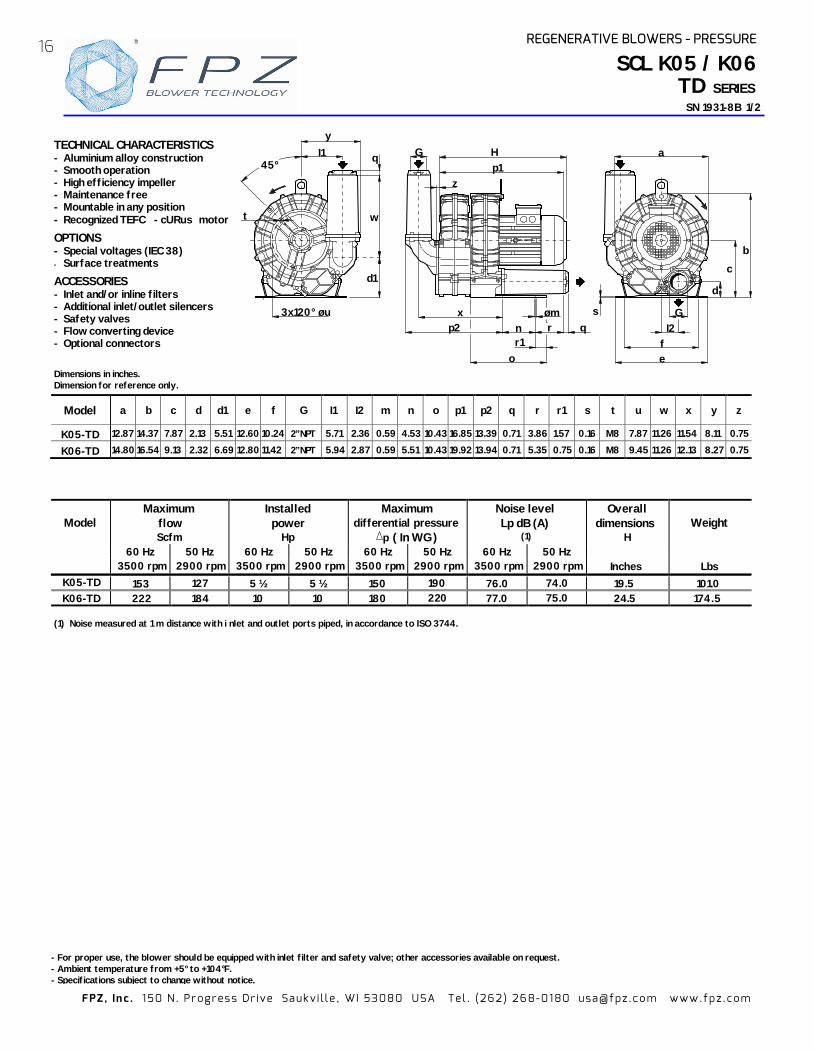
K05-TD
153 127
5 ½ 5 ½ 150 190 76.0 74.0 19.5 101.0
K06-TD
222
184
10 10 180 220 77.0 75.0 2 4.5 174.5
(1) Noise measured at 1 m distance with i nlet and outlet ports piped, in accordance to ISO 3744.
Model a b c d d1 e f G I1 I2 m n o p1 p2 q r r1 s t u w x y z
K05-TD 12.87 14.37 7.87 2.13 5.51 12.60 10.24 2” NPT 5.71 2.36 0.59 4.53 10.43 16.85 13.39 0.71 3.86 1.57 0.16 M8 7.87 11.26 11.54 8.11 0.75
K06-TD 14.80 16.54 9.13 2.32 6.69 12.80 11.42 2” NPT 5.94 2.87 0.59 5.51 10.43 19.92 13.94 0.71 5.35 0.75 0.16 M8 9.45 11.26 12.13 8.27 0.75
SCL K05 / K06TD SERIES
-8 SN 1931 B 1/2
- For proper use, the blower should be equipped with inlet filter and safety valve; other accessories available on request. - Ambient temperature from +5° to +104°F. - Specifications subject to change without notice.
a
d
b
c
s
e f
I2 G
t
3x120° øu
y I1 q
d1
w
45° G
p1 H
z
q
o
p2 x
n r øm
r1
TECHNICAL CHARACTERISTICS - Aluminium alloy construction - Smooth operation - High efficiency impeller - Maintenance free - Mountable in any position - Recognized TEFC - cURus motor
OPTIONS - Special voltages (IEC 38) - Surface treatments
ACCESSORIES - Inlet and/or inline filters - Additional inlet/outlet silencers - Safety valves - Flow converting device - Optional connectors
Dimensions in inches. Dimension for reference only.
16 REGENERATIVE BLOWERS - PRESSURE®

FPZ , In c . 1 50 N . Pr ogr es s Dr ive Sa uk v i l l e , WI 5308 0 USA Tel . (262 ) 26 8-01 80 usa@ fpz .c o m www.fp z .c om
CAPA
CITY
A
BSO
RBED
PO
WER
TE
MPE
RATU
RE
INCR
EASE
SCL K05 / K06
TD SERIES -8 SN 1931 B 2/2
60 Hz
5 1/2
0
20
40
60
80
100
120
140
160
200
In W
G
0 50 100 150 200 250 Scfm
K06-TD
10
K05-TD 1
2
4
5
6
0
3
7
p
psig
0
20
40
60
80
100
120
140
In W
G
160
180
240
200
K05-TD K06-TD
5 1/2
Scfm 0 50 100 150 200
50 Hz
1
2
4
5
6
0
3
7
8
p
psig
60 Hz
0
20
40
60
80
100
120
140
160
In W
G 200
K06-TD
0 1 2 3 4 5 6 8 10 Hp 7 9
K05-TD
1
2
4
5
6
0
3
7
p
psig
K05-TD K06-TD
50 Hz
0 1 2 3 4 5 6 7 8 Hp 10 11 0
20
40
60
80
100
120
140
180
In W
G
160
240
1
2
4
5
6
0
3
7
8
p
psig
60 Hz
0
20
40
60
80
100
120
140
200
In W
G
160
0 20 40 60 80 100 120 140 160 180 °F
K05-TD
K06-TD
1
2
4
5
6
0
3
7
p
psig
0
20
40
60
80
100
120
140
240
In W
G
160
0 20 40 60 80 100 120 140 160 180 °F
K05-TD
K06-TD
50 Hz
180
1
2
4
5
6
0
3
7
8
p
psig
Curves refer to air at 68°F temperature and 29.92 Hg atmospheric pressure (abs) measured at inlet p ort. Values for flow, power consumption and temperature rise +/-10% tolerance. Data subject to change without notice.
In
REGENERATIVE BLOWERS - PRESSURE 17
10
®
Model Maximum
flow Scfm
Installed power
Hp
Maximum differential pressure
∆∆∆ ( In WG )
Noise level Lp dB (A)
(1)
Overall dimensions
H Weight
60 Hz 50 Hz 60 Hz 50 Hz 60 Hz 50 Hz 60 Hz 50 Hz 3500 rpm 2900 rpm 3500 rpm 2900 rpm 3500 rpm 2900 rpm 3500 rpm 2900 rpm Inches Lbs
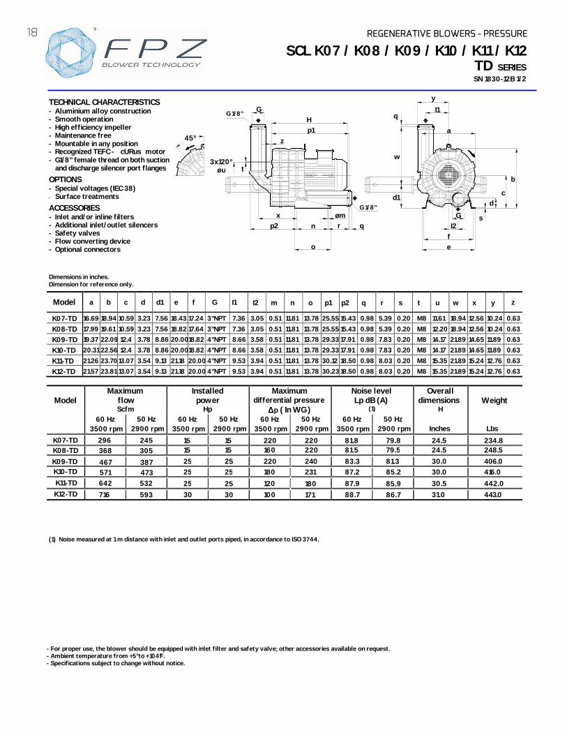
K07-TD 296 245
15 15 220 220 81.8 79.8 24.5 K08-TD 368 305 15 15 160 81.5 79.5 24.5 248.5 K09-TD 467 387
25 25 220 240 83.3 81.3 30.0
K10-TD 571 473 25 25 180 231 87.2 85.2 30.0 K11-TD 642 532
25 25 120 1 87.9 85.9 30.5 442.0
K12-TD 716 593
30 30 100 1 88.7 86.7 3 .0 4 0
(1) Noise measured at 1 m distance with inlet and outlet ports piped, in accordance to ISO 3744.
Model a b c d d1 e f G I1 z
K07-TD 16.69 18.94 10.59 3.23 7.56 18.43 17.24 3”NPT 7.36 3.05 0.51 11.81 13.78 25.55 15.43 0.98 5.39 0.20 M8 11.61 18.94 12.56 10.24 0.63
K08-TD 17.99 19.61 10.59 3.23 7.56 18.82 17.64 3”NPT 7.36 3.05 0.51 11.81 13.78 25.55 15.43 0.98 5.39 0.20 M8 12.20 18.94 12.56 10.24 0.63
K09-TD 19.37 22.09 12.4 3.78 8.86 20.00 18.82 4”NPT 8.66 3.58 0.51 11.81 13.78 29.33 17.91 0.98 7.83 0.20 M8 14.17 21.89 14.65 11.89 0.63
K10-TD 20.31 22.56 12.4 3.78 8.86 20.00 18.82 4”NPT 8.66 3.58 0.51 11.81 13.78 29.33 17.91 0.98 7.83 0.20 M8 14.17 21.89 14.65 11.89 0.63
K11-TD 21.26 23.70 13.07 3.54 9.13 21.18 20.00 4”NPT 9.53 3.94 0.51 11.81 13.78 30.12 18.50 0.98 8.03 0.20 M8 15.35 21.89 15.24 12.76 0.63 K12-TD 21.57 23.81 13.07 3.54 9.13 21.18 20.00 4”NPT 9.53 3.94 0.51 11.81 13.78 30.23 18.50 0.98 8.03 0.20 M8 15.35 21.89 15.24 12.76 0.63
45°
q
d1
w
y
I1
d
b
e f
a
I2 G
c
s
3x120° øu
q
G
o
p1 H
p2 x
z
t
n r øm
SCL K07 / K08 / K09 / K10 / K11 / K12TD SERIESSN 1830-12B 1/2
- For proper use, the blower should be equipped with inlet filter and safety valve; other accessories ailable on request. - Ambient temperature from +5° to +104°F. - Specifications subject to change without notice.
TECHNICAL CHARACTERISTICS - Aluminium alloy construction - Smooth operation - High efficiency impeller - Maintenance free - Mountable in any position - Recognized TEFC - cURus motor - G1/8” female thread on both suction
and discharge silencer port flanges
OPTIONS - Special voltages (IEC 38) - Surface treatments
ACCESSORIES - Inlet and/or inline filters - Additional inlet/outlet silencers - Safety valves - Flow converting device - Optional connectors
Dimensions in inches. Dimension for reference only.
G 1/8”
G 1/8”
p
I2 m n o p1 p2 q r s t u w x y
18 REGENERATIVE BLOWERS - PRESSURE
234.8
av
®
220
780
406.0 416.0
43.11

FPZ , In c . 1 50 N . Pr ogr es s Dr ive Sa uk v i l l e , WI 5308 0 USA Tel . (262 ) 26 8-01 80 usa@ fpz .c o m www.fp z .c om
CAPA
CITY
A
BSO
RBED
PO
WER
TE
MPE
RATU
RE IN
CREA
SE
SCL K07 / K08 / K09 / K10 / K11 / K12TD SERIESSN 1830-12B 2/2
Curves refer to air at 68° F temperature and 29.9 Hg atmospheric pressure (abs) measured at inlet ort. Values for flow, power consumption and temperature rise: +/-10% tolerance. Data subject to change without notice.
0
1
2
3
4
5
6
7
8
9
p p
sig
K10 -TD
0
20
40
60
80
100
120
140
160
180
200
260
0 20 40 60 80 100 120 140 °F
In W
G
K07-TD
K08-TD
K09-TD
K11 -TD
0
1
2
3
4
5
6
7
8
9
p p
sig
Scfm
25
100 200 300 400 500 600 700
100
120
140
160
180
200
220
260
0
20
40
60
80
In W
G
15
K07-TD
K08-TD
15
K09-TD
25
K10 -TD
K11 -TD
25
800
60 Hz
30
0
1
2
3
4
5
6
7
8
9
p p
sig
K10 -TD
0
20
40
60
80
100
120
140
160
180
200
260
0 5 10 15 20 Hp
In W
G
K08-TD
K07-TD
25
K09-TD
K11 -TD
30
K12 -TD
K12 -TD
60 Hz
60 Hz
K12 -TD
0
1
2
3
4
5
6
7
8
9
10
p p
sig
0
1
2
3
4
5
6
7
8
9
10
p p
sig
0 20
40 60 80
100
120 140 160
180 200
220
280
0 20 40 60 80 100 120 140 160 180 °F
50 Hz
In W
G
K10 -TD
K07-TD
K08-TD
K09-TD
K11 -TD
0
1
2
3
4
5
6
7
8
9
10
p p
sig
K10 -TD
0
20
40
60
80
100
120
140
160
180
200
220
240
280
0 100 200 300 400 500 600 Scfm
In W
G
K08-TD
K07-TD K09-TD K11 -TD
15 15
25
25
25
700
30
K12 -TD
50 Hz
Hp
K12 -TD
K10 -TD
0 20 40 60 80
100
120 140 160
180 200 220
280
0 5 10 15 20
In W
G
K08-TD
K11-TD
25
K07-TD
K09-TD
K12-TD
50 Hz
30
2 In
REGENERATIVE BLOWERS - PRESSURE 19®
p

FPZ , In c . 1 50 N . Pr ogr es s Dr ive Sa uk v i l l e , WI 5308 0 USA Tel . (262 ) 26 8-01 80 usa@ fpz .c o m www.fp z .c om
STANDARD FEATURES - Low weight cast aluminum construction. - Quiet operation with integral inlet and
outlet muffling. - Recognized TEFC - cURus motor. - High efficiency / low noise impeller
design. - No lubrication / maintenance required. - Allowed ambient: +5 °F to +104 °F. - Mountable in any plane.
OPTIONS - Special voltages. - Surface treatment or plating. - Gas tight sealing. - Special designs available.
ACCESSORIES - Inlet and/or inline filters. - Additional inlet/outlet silencers. - Safety valves. - Flow converting devices. - Optionals connectors
SCL 06
SN 2673-1B 1/2
Dimensions in inches. Dimension for reference only.
- For proper use, the blower should be equipped with inlet filt- Ambient temperature rom +5° to +104°F. - Specifications subject to change without notice.
(1) Noise measured at 1 m distance with inlet and outlet ports piped, in accordance to ISO 3744.
Model Maximum
flow Scfm
Installed power
Hp
Maximum differential pressure
p ( In WG)
Noise level Lp dB (A)
(1)
Overall dimensions
H Weight
60 Hz 50 Hz 60 Hz 50 Hz 60 Hz 50 Hz 60 Hz 50 Hz 3500 rpm 2900 rpm 3500 rpm 2900 rpm 3500 rpm 2900 rpm 3500 rpm 2900 rpm Inches Lbs
1/3 - 36 - 58.7 - 06 39 32 1/2 1/2 52 36 59.0 58.0 10.60 18.50
“P” version
1”NPT8.6
3.150.59 1.38
7.68.7
7.102.95
ø 0.43H
1.06
M5
5.35 DIA
4.644.56
4.373.38
4.13
M5
06 SERIES
er and safety valve; other accessories available on request. f
20 REGENERATIVE BLOWERS - PRESSURE
10.60 18.30
FPZ , In c . 1 50 N . Pr ogr es s Dr ive Sa uk v i l l e , WI 5308 0 USA Tel . (262 ) 26 8-01 80 usa@ fpz .c o m www.fp z .c om
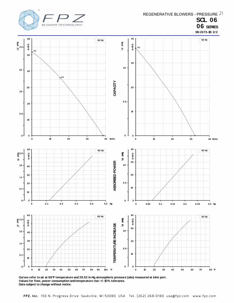
Curves refer to air at 68°F temperature and 29.92 In HgValues for flow, power consumption and Data subject to change without notice.
ABS
ORB
ED P
OW
ER
TEM
PERA
TURE
INCR
EASE
SCL 06
SN 2673-
CAPA
CITY
In W
G
60
0
10
20
30
40
0 0.1 Hp0.2 0.3 0.4 0 5
60 Hz
0
1,0
2.0
p
psig
1.5
0,5
0
10
20
40
In W
G
30
0 Scfm10 20 30 40
50 Hz
1/2
p
psig
1.0
0
0.5
40
0 30 50 60 80 °F0
10
20
In W
G
60 Hz
20
30
10 40 70
60
90 1000
1,0
2.0
p
psig
1.5
0,5
In W
G
0
10
20
40
30
Hp
50 Hz
0 0 05 0 1 0 1 5 0 2 0 30.25
p
psig
p
ps
ig
1.0
0
0.5
40
0
10
20
In W
G
30
0 30 50 60 80 °F
50 Hz
2010 40 70
1.0
0
0.5
p
psig
p
ps
ig
p
psig
0
1.0
2.0
1.5
0.5
Scfm0
10
20
30
40
50
60
In W
G
0 10 20 30 40
60 Hz
1/2
1/3
06 SERIES
. . . . ..
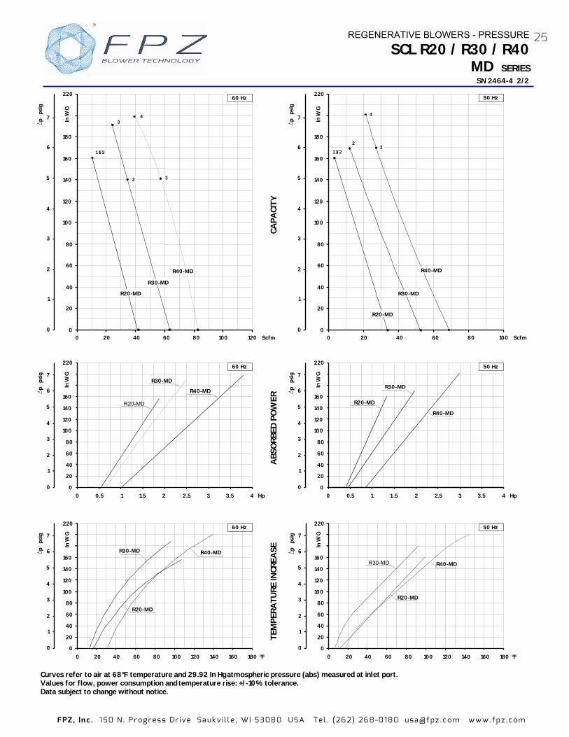
atmospheric pressure (abs) measured at inlet port.
REGENERATIVE BLOWERS - PRESSURE 21
temperature rise: +/-10% tolerance.
1B 2/2
FPZ , In c . 1 50 N . Pr ogr es s Dr ive Sa uk v i l l e , WI 5308 0 USA Tel . (262 ) 26 8-01 80 usa@ fpz .c o m www.fp z .c om
Model Maximum
flow Scfm
Installed power
Hp
Maximum differential pressure
∆p ( In WG)
Noise level Lp dB (A)
(1)
Overall dimensions
H Weight
60 Hz 50 Hz 60 Hz 50 Hz 60 Hz 50 Hz 60 Hz 50 Hz 3500 rpm 2900 rpm 3500 rpm 2900 rpm 3500 rpm 2900 rpm 3500 rpm 2900 rpm Inches Lbs
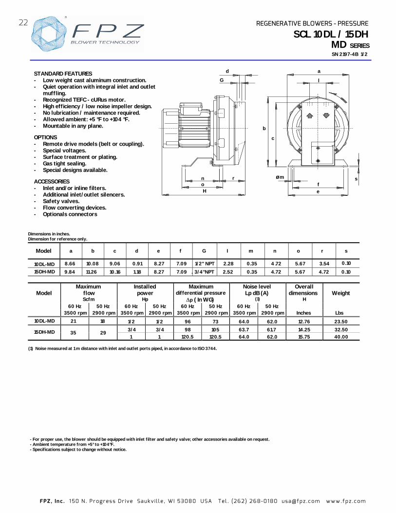
21 18 1/2 1/2 96 73 64.0 62.0 12.76 23.50 3/4 3/4 98 105 63.7 61.7 14.25 32.50 35 29 1 1 120.5 120.5 64.0 62.0 15.75 40.00
SCL 10DL / 15DH
SN 2197-4B 1/2
STANDARD FEATURES - Low weight cast aluminum construction. - Quiet operation with integral inlet and outlet
muffling. - Recognized TEFC - cURus motor.- High efficiency / low noise impeller design. - No lubrication / maintenance required. - Allowed ambient: +5 °F to +104 °F. - Mountable in any plane.
OPTIONS - Remote drive models (belt or coupling). - Special voltages. - Surface treatment or plating. - Gas tight sealing. - Special designs available.
ACCESSORIES - Inlet and/or inline filters. - Additional inlet/outlet silencers. - Safety valves. - Flow converting devices. - Optionals connectors
Model a b c d e f G I m n o r s
8.66 10.08 9.06 0.91 8.27 7.09 1/2" NPT 2.28 0.35 4 .72 5.67 3.54
9.84 11.26 10.16 1.18 8.27 7.09 3 4"NPT 2.52 0.35 4.72 5.67 4.72 0.10
d
G
rnoH
l
a
øm fe
b
c
s
Dimensions in inches. Dimension for reference only.
- For proper use, the blower should be equipped with inlet filter and safety valve; other accessories available on request. - Ambient temperature from +5° to +104°F. - Specifications subject to change without notice.
(1) Noise measured at 1 m distance with inlet and outlet ports piped, in accordance to ISO 3744.
MD SERIES
.
0.10
22 REGENERATIVE BLOWERS - PRESSURE
/
10DL-MD
10DL-MD
15DH-MD
15DH-MD

FPZ , In c . 1 50 N . Pr ogr es s Dr ive Sa uk v i l l e , WI 5308 0 USA Tel . (262 ) 26 8-01 80 usa@ fpz .c o m www.fp z .c om
Curves refer to air at 68°F temperature and 29.92 In Hg atmospheric pressure (abs) measured at inlet port. Values for flow, power consumption and temperature rise: +/-10% tolerance. Data subject to change without notice.
ABS
ORB
ED P
OW
ER
TEM
PERA
TURE
INCR
EASE
SCL 10DL / 15DH
SN 2197-
CAPA
CITY
p
psig
0
1
2
3
4
5
p
psig
0
1
2
3
4
5
Hp0 0,2 0,4 0,6 0,8 1
In W
G
0
20
40
60
80
100
140
10DL
15DH
50 Hz
p
psig
0
1
2
3
4
5
0
p
psig
1
2
3
4
5
0
20
40
60
80
100
120
140
In W
G
0 Scfm10 20 40 30
60 Hz
1
3/41/2
10DL
15DH
In W
G
0
20
40
60
80
100
140
0 0,2 Hp0,4 0,6 0,8 1
60 Hz
10DL 15DH
p
psig
0
1
2
3
4
5
p
psig
1
2
3
4
5
0
1/2
0
20
40
60
80
100
120
140
In W
G
0 Scfm10 20 30 40
50 Hz
1
3/4
15DH
10DL
0 20 40 60 80 100 °F0
20
40
60
80
100
140
In W
G
15DH
10DL
50 Hz
°F0
20
40
60
80
100
140
In W
G
0 20 40 60 80 100
60 Hz 15DH
10DL
1/2
0
20
40
60
80
100
120
140
In W
G
0 Scfm10 20 30 40
50 Hz
1
3/4
15DH
10DL
MD SERIES
REGENERATIVE BLOWERS - PRESSURE23
B 2/24

FPZ , In c . 1 50 N . Pr ogr es s Dr ive Sa uk v i l l e , WI 5308 0 USA Tel . (262 ) 26 8-01 80 usa@ fpz .c o m www.fp z .c om
- For proper use, the blower should be equipped with inlet filter and relief valve; other accessories available on request. - Ambient temperature rom +5° to +104°F. - Specifications subject to change without notice.
Model Maximum
flow Scfm
Installed power
Hp
Maximum differential pressure
∆p ( In WG)
Noise level Lp dB (A)
(1)
Overall dimensions
H Weight
60 Hz 50 Hz 60 Hz 50 Hz 60 Hz 50 Hz 60 Hz 50 Hz 3500 rpm 2900 rpm 3500 rpm 2900 rpm 3500 rpm 2900 rpm 3500 rpm 2900 rpm Inches Lbs
1 ½ 1 ½ 161 161 13. 4 .5 2 2 140 69.2 15.58 57.3 3 - 191 - 72.8 15.55 66.1 3 3 141 170 72.8 16.22 77.2 4 4 201 201 73.3 1 . 9 88
(1) Noise measured at 1 m distance with inlet and outlet ports piped, in accordance to ISO 3744.
SCL R20 / R30 / R40
SN 2464-4 1/2
STANDARD FEATURES - Low weight cast aluminum construction. - Quiet operation with integral inlet and outlet
muffling. - Recognized TEFC - cURus motor. - High efficiency / low noise impeller design. - No lubrication / maintenance required. - Allowed ambient: +5 °F to +104 °F. - Mountable in any plane.
OPTIONS - Remote drive models (belt or coupling). - Special voltages. - Surface treatment or plating. - Gas tight sealing. - Special designs available.
ACCESSORIES - Inlet and/or inline filters. - Additional inlet/outlet silencers. - - Flow converting devices. - Optionals connectors
Dimensions in inches. Dimension for reference only.
Model a b c d e f G I m n o p1 q t
11.14 12.17 6.57 1.85 1” ¼ NPT 12.56 7.36 0.71 0.87 M6 09 13.78 7.76 0 .71
sl
G
d
c
a
fe
b
r
øm
p1
o
nq
H
3x120° øu
t
MD
11
0. 87 5 91
REGENERATIVE BLOWERS - PRESSURE
3.54 0.39 5.91 7.87 0.71 1.77 13.58 0R2 -MD
35 R20-MD 41
9 . 2 5 8. . 2 70.390.39
R30-MD R40-MD 14.65
13.62 1.85 1.85
9 . 2 5 8 . 2 79 . 2 5 8 . 2 7
1” ¼ NPT 1” ¼ NPT
3.54 3.54
5.91 5.91
7.877.87
3.944.33
r
1.77 1.77 0.87
s
M8
M6
u
. 7.
8.86
R30-MD
R40-MD
54 65
69 81
170 72.2
68.5 66.5
69.7 70.8
39
7 0 .2
SERIES
71.3
Relief valves.
8
24
f
FPZ , In c . 1 50 N . Pr ogr es s Dr ive Sa uk v i l l e , WI 5308 0 USA Tel . (262 ) 26 8-01 80 usa@ fpz .c o m www.fp z .c om
Curves refer to air at 68°F temperature and 29.92 In Hg atmospheric pressure (abs) measured at inlet port. Values for flow, power consumption and Data subject to change without notice.
CAPA
CITY
A
BSO
RBED
P
TEM
PERA
TURE
INCR
EASE
SN 2464- 2/2
p
psig
0
1
2
3
4
5
6
7
0
20
40
60
80
100
120
140
160
180
220
0 Scfm
In W
G
20 40 60 80 100 120
60 Hz
3
2
3
4
p
psig
0
1
2
3
4
5
6
7
In W
G
0
20
40
60
80
100
120
140
160
220
Hp
50 Hz
0 0.5 1 1 5 2 2 5 3 3 5 4
p
psig
0
1
2
3
4
5
6
7
0
20
40
60
80
100
120
140
160
220
0 20 40 60 80 100 120 140 160 180 °F
In W
G 50 Hz
p
psig
0 1
2
3
4
5
6
7
In W
G
0
20
40
60
80
100
120
140
160
220
0 0.5 1 Hp
60 Hz
1.5 2 2.5 3 3.5 4
p
psig
0 1
2
3
4
5
6
7
0
20
40
60
80
100
120
140
160
220
0 20 40 60 80 100 120 140 160 180 °F
In W
G
p
psig
0
1
2
3
4
5
6
7
0
20
40
60
80
100
120
140
160
180
220
0 Scfm
50 Hz
In W
G
20 40 60 80 100
1 1/2
2
4
3
D SERIES
. . .
REGENERATIVE BLOWERS - PRESSURE
OW
ER
1 1/2
R20-MD
R20-MD R20-MD
4
R40-MD
R30-MD
R40-MD
R30-MD
R40-MD
temperature rise: +/-10% tolerance.
R40-MD R 0-MD 3
60 Hz
R40-MD R30-MD
R20-MD
R30-MD R40-MD
R20-MD
DR -M20
R30-MD
SCL R20 / R30 / R40M
25

FPZ , In c . 1 50 N . Pr ogr es s Dr ive Sa uk v i l l e , WI 5308 0 USA Tel . (262 ) 26 8-01 80 usa@ fpz .c o m www.fp z .c om
TECHNICAL CHARACTERISTICS - Aluminium alloy construction - Smooth operation - High efficiency impeller - Maintenance free - Mountable in any position OPTIONS - Special voltages (IEC 38) - Surface treatments ACCESSORIES - Inlet and/or inline filters - Additional inlet/outlet silencers - Safety valves - Flow converting device - Optional connectors
Model Maximum
flow Scfm
Installed power
Hp Size
Maximum differential pressure
Dp ( In WG )
Noise level Lp dB (A)
(1) Weight
(2) 60 Hz 50 Hz 60 Hz 50 Hz 60 Hz 50 Hz Lbs 3500 rpm 2900 rpm 3500 rpm 2900 rpm 3500 rpm 2900 rpm GOR GVR
3/4 NEMA 56C 64 62.0 K03-MS 52 43
1 NEMA 56C 80 60
62.3 60.0 22.00 17.60
1 ½ NEMA 56C 58 80 64.8 62.8 2 NEMA 56C 85 65.0 K04-MS 98 81 3 NEMA 56C 100
90 65.2
63.0 27.60 22.00
2 NEMA 143-5TC 52 70 70.5 68.5 NEMA 143-5TC
35.00 28.003
NEMA 182-4TC 90 10 70.8 68.8 K05-MS 156 129
5 NEMA 182-4TC 130 120 71.1 69.1 34.50 27.00
NEMA 143-5TC 46.00 38.403
NEMA 182-4TC 65 73.0 71.0
5 NEMA 182-4TC 85 110 73.6 71.6 K06-MS 216 179
7 ½ NEMA 182-4TC 140 135 73.9 71.9
40.80 38.00
(1) Noise measured at 1 m distance with inlet and outlet ports piped, in accordance to ISO 3744. (2) Value is refered to weight of the machine without electric motor.
SCL K03 / K04 / K05 / K06SERIES - GOR/GVR RANGE
SN 2580-1 1/2
- For proper use, the blower should be equipped with inlet filter - Ambient temperature from +5° to +104°F. - Specifications subject to change without notice.
For dimensions, please refer to drw: -- GG OO RR range: SS II 11 885522 -- GG VVRR range: SS II 11 994466
GOR Range GVR Range
SCL Kxx-MS GOR-A SCL Kxx-MS GOR-C
1
and safety valve; other accessories available on request.
26 REGENERATIVE BLOWERS - PRESSURE
MS
50

FPZ , In c . 1 50 N . Pr ogr es s Dr ive Sa uk v i l l e , WI 5308 0 USA Tel . (262 ) 26 8-01 80 usa@ fpz .c o m www.fp z .c om
CAPA
CITY
A
BSO
RBED
PO
WER
TE
MPE
RATU
RE IN
CREA
SE
SCL K03 / K04 / K05 / K06SERIES - GOR/GVR RANGE
SN 2580-1 2/2
Curves refer to air at 68°F temperature and 29.92 In HgValues for flow, power consumption and emperature rise: +/-10% tolerance. Data subject to change without notice.
K05-MS K06-MS K04-MS K03-MS
0
20
40
60
80
100
120
160
In W
G
3
3/4
1
1 1/2
2
3
2
5
3
5
7 1/2
0 50 100 150 200 250 Scfm
60 Hz
140
0
1
2
3
4
5 p
psig
K06-MS
K05-MS
K04-MS
K03-MS
0
20
40
60
80
100
160
In W
G
120
0 1 2 3 4 5 6 7 Hp
60 Hz
0
1
2
3
4
5
p
psig
0 20 40 60 80 100 120 140 °F
0
20
40
60
80
100
160
In W
G
K06-MS
K04-MS
K03-MS
K05-MS 120
60 Hz
0
1
2
3
4
5
p
psig
0
1
2
3
4
5
p
psig
In W
G
0
20
40
60
80
100
120
140
160
0 50 100 150 200 Scfm
50 Hz
5
3
3
7 1/2
5
1 1/2
2
3/4
2
K03-MS K04-MS K05-MS K06-MS
0
1
2
3
4
5
p
psig
In W
G
0
20
40
60
80
100
120
160
0 1 2 3 4 5 6
50 Hz
Hp
K05-MS
K06-MS
K04-MS
K03-MS
0
1
2
3
4
5
p
psig
0 20 40 60 80 100 120 140 160 180 200 °F
In W
G
0
20
40
60
80
100
120
16050 Hz
K05-MS K06-MS
K04-MS
K03-MS
atmospheric pressure (abs) measured at inlet port. t
REGENERATIVE BLOWERS - PRESSURE27
MS

FPZ , In c . 1 50 N . Pr ogr es s Dr ive Sa uk v i l l e , WI 5308 0 USA Tel . (262 ) 26 8-01 80 usa@ fpz .c o m www.fp z .c om
Model Maximum
flow Scfm
Installed power
Hp Size
Maximum differential pressure
∆p ( In WG )
Noise level Lp dB (A)
(1)
Weight (2)
60 Hz 50 Hz 60 Hz 50 Hz 60 Hz 50 Hz 3500 rpm 2900 rpm 3500 rpm 2900 rpm 3500 rpm 2900 rpm Lbs
5 NEMA 182-4TC 70 86 79.0 77.0 110.5 NEMA 182-4TC 110.5
7 ½ NEMA 213-5TC
130 79.3 110.5
K07-MS 294 243
10 NEMA 213-5TC 140
79.6 77.3
110.5
5 NEMA 182-4TC 38 52 79.7 77.7 127.0 NEMA 182-4TC 127.0
7 ½ NEMA 213-5TC
90 80.0 78.0 127.0
10 NEMA 213-5TC 115 125 80.3 78.3 127.0 NEMA 213-5TC 127.0
K08-MS 381 316
15 NEMA 254-6TC
170 160 80.6 78.6 130.6
NEMA 182-4TC 133.4 7 ½
NEMA 213-5TC 50 63 80.2 78.2
133.4 10 NEMA 213-5TC 80 95 80.5 78.5 133.4
NEMA 213-5TC 133.4 15
NEMA 254-6TC 140 155 81.0 79.0
137.0
K09-MS 471 390
20 NEMA 254-6TC 180 170 81.3 79.3 137.0
NEMA 182-4TC 147.3 7 ½
NEMA 213-5TC 30 50 80.1 78.1
147.3 10 NEMA 213-5TC 60 80 80.5 78.5 147.3
NEMA 213-5TC 147.3 15
NEMA 254-6TC 110 135 81.0 79.0
151.0 20 NEMA 254-6TC 160
K10-MS 556 460
25 NEMA 284-6TSC 200 190
81.6 79.4
147.3
10 NEMA 213-5TC 40 53 82.0 80.0 170.0 NEMA 213-5TC 170.0
15 NEMA 254-6TC
80 97 82.4 80.4 176.4
20 NEMA 254-6TC 125 140 82.7 80.7 176.4 25 NEMA 284-6TSC 160 170.0
K11-MS 650 539
30 NEMA 284-6TSC 200 190
86.0 83.6
170.0
NEMA 213-5TC 177.7 15
NEMA 254-6TC 52 90 82.9 80.9
184.1 20 NEMA 254-6TC 85 130 83.2 81.2 184.1 25 NEMA 284-6TSC 120 30 NEMA 284-6TSC 150 177.7
K12MS 726 602
40 NEMA 324-6TSC 180 170
86.9 84.1
193.2
TECHNICAL CHARACTERISTICS - Aluminium alloy construction - Smooth operation - High efficiency impeller - Maintenance free - Mountable in any position
OPTIONS - Special voltages (IEC 38) - Surface treatments
ACCESSORIES - Inlet and/or inline filters - Additional inlet/outlet silencers - Safety valves - Flow converting device - Optional connectors
- For proper use, the blower should be equipped with inlet filter - Ambient temperature from +5° to +104°F.
- Specifications subject to change without notice. (1) Noise measured at 1 m distance with inlet and outlet ports piped, in accordance to ISO 3744. (2) Value is refered to weight of the machine without electric motor
SCL K07 / K08 / K09 / K10 / K11 / K12SERIES - GOR/GVR RANGE
SN 2134-3 1/2
GOR Range
SCL Kxx-MS GOR-C
SCL Kxx-MS GOR-A SCL Kxx-MS GOR-B
GVR Range
For dimensions, please refer to drw: GG OO RR range: SS II 11 887733 GG VVRR range: SS II 11 992200
68
81.4
86.1
85.6
86.5
170
151.0
177.7
28 REGENERATIVE BLOWERS - PRESSURE
and safety valve; other accessories available on request.
MS

FPZ , In c . 1 50 N . Pr ogr es s Dr ive Sa uk v i l l e , WI 5308 0 USA Tel . (262 ) 26 8-01 80 usa@ fpz .c o m www.fp z .c om
Curves refer to air at 68°F temperature and 29.92 In Hg atmospheric pressure (abs) measured at inlet port. Values for flow, power consumption and Data subject to change without notice.
CAPA
CITY
A
BSO
RBED
PO
WER
TE
MPE
RATU
RE IN
CREA
SE
SCL K07 / K08 / K09 / K10 / K11 / K12SERIES - GOR/GVR RANGE
SN 2134-3 2/2
0
1
2
3
4
5
6
7
K11-MS
K08-MS
K09-MS K10-MS
K07-MS
60 Hz
0
20 40 60 80
100 120 140 160
In W
G
220
Hp 0 10 15 25 305 20
K12-MS
0
20
40
60
80
100
120
140
160
180
In W
G
220
0 100 200 300 400 Scfm700 500 600
K08-MS
K09-MS K07-MS
K10-MS
15
10
10
20 25
20
15
20
7 1/2
10
7 1/2
10
K11-MS
5 7 1/2
15
15
5
7 1/2
K12-MS
25
20
15
50 Hz
0
1
2
3
4
5
6
7
0
20
40
60
80
100
120
220
In W
G
140
160
Hp0 10 15 255 20
K07-MS
K11-MS
K08-MS K10-MS K12-MS
K09-MS
50 Hz
0
1
2
3
4
5
6
7
0
1
2
3
4
5
6
7
0
20
40
60
80
100
120
140
160
220
In W
G 50 Hz
K09-MS
K12-MS
K08-MSK10-MS
K11-MS
0 20 40 60 80 100 120 140 160 180 °F
K07-MS
0
1
2
3
4
5
6
7
K09-MS
K07-MS
K08-MS
K10-MS
K11-MS
0 20 40 60 80 100 120 140 160 °F 180
0 20
40
60
80
100
120
140
In W
G
160
220 60 Hz
K12-MS
0
1
2
3
4
5
6
7
0
20
40
60
80
100
120
140
180
In W
G
160
220
400 100 200 300 500 Scfm 700 8000 600
K08-MS K07-MS K09-MS
K10-MS
10 15
5
7 1/2
10
5
7 1/2
10
20
15
7 1/2
10
15
20
25 30
25
20
15
10
K11-MS K12-MS
15
20
30
40
60 Hz
7 1/2
25
temperature rise: +/-10% tolerance.
p
psig
p
psig
p
psig
p
psig
p
psig
p
psig
REGENERATIVE BLOWERS - PRESSURE29
MS

FPZ , In c . 1 50 N . Pr ogr es s Dr ive Sa uk v i l l e , WI 5308 0 USA Tel . (262 ) 26 8-01 80 usa@ fpz .c o m www.fp z .c om
- For proper use, the blower should be equipped with inlet filter and safety valve; other accessories available on request. - Ambient temperature from +5° to +104°F. - Specifications subject to change without notice.
(1) Noise measured at 1 m distance with inlet and outlet ports piped, in accordance to ISO 3744. (2) Value is refered to weight of the machine without electric motor.
SCL K05 / K06
SN 2686-1 1/2
For dimensions, please refer to drw: -- GG OO RR range: SS II 2211 2233 -- GG VVRR range: SS II 2211 3355
Model Maximum
flow m³/h
Installed power
Hp Size
Maximum differential pressure
∆p ( in WG )
Noise level Lp dB (A)
(1)
Weight (2)
60 Hz 50 Hz 60 Hz 50 Hz 60 Hz 50 Hz Lbs 3500 rpm 2900 rpm 3500 rpm 2900 rpm 3500 rpm 2900 rpm GOR GVR
5.0 60 85 75.5 73.5 K05-TS 290 241 7.5
NEMA 182-4TC100 110 77.5 75.5
72.75 68.35
7.5 55 77 77.5 75.5 10 80 110 77.8 75.8 K06-TS 400 331
15
NEMA 213-5TC
130 120 78.4 76.4
112.45 108.00
TECHNICAL CHARACTERISTICS - Aluminium alloy construction - Smooth operation - High efficiency impeller - Maintenance free - Mountable in any plane - G1/8'' female thread on both suction and discharge silencer port flanges. OPTIONS - Special voltages (IEC 38) - Surface treatments
SCL Kxx-TS GOR-C
G 1/8”
GVR RangeGOR Range
G 1/8”
SCL Kxx-TS GOR-A SCL Kxx-TS GOR-B SCL Kxx-TS GOR-C
ACCESSORIES
- Inlet and/or inline filters - Additional inlet/outlet silencers - Safety valves - Flow converting device - Optional connectors
30 REGENERATIVE BLOWERS - PRESSURE
SERIES RANGE TS - GOR/GVR

FPZ , In c . 1 50 N . Pr ogr es s Dr ive Sa uk v i l l e , WI 5308 0 USA Tel . (262 ) 26 8-01 80 usa@ fpz .c o m www.fp z .c om
SCL K05 / K06SERIES RANGE
SN 2686- 2/2
CAPA
CITY
A
BSO
RBED
PO
WER
TE
MPE
RATU
RE IN
CREA
SE
Curves refer to air at 68°F temperature and 29.92 In Hg atmospheric pressure (abs) measured at inlet port. Values for flow, power consumption and Data subject to change without notice.
K05-TS
K06-TS
0 20 40 60 80 °F 0
20
40
60
140
In W
G
60 Hz
K06-TS
50 Hz
0 20 40 80 140 °F 60 100 120
K05-TS
80
100
100 1200
20
40
60
80
120
0
1
2
3
4
5
0
1
2
3
4
5
p
psig
p
psig
p
psig
60 Hz
0
20
40
60
140
0 1 2 3 4 5 6 7 8 Hp
In W
G
9 10
K05-TS
K06-TS
0
1
2
3
4
5
80
100
60 Hz
In W
G
0
20
40
60
140
0 100 200 300 400 Scfm
K05-TS
5
K06-TS
7 1/2
0
1
2
3
4
5
80
100
120
7 1/2
15
10
50 Hz
In W
G
0
20
40
60
140
0 100 200 300 400 Scfm
K05-TS
5
K06-TS
7 1/2
0
1
2
3
4
5
80
100
120
7 1/2
15
10
50 150 250 350
p
psig
50 Hz
0
20
40
60
140
0 1 2 3 4 5 6 7 8 Hp
In W
G
9 10
K05-TS
K06-TS
0
1
2
3
4
5
80
100
100
140
11 12 13 14 15
500
p
psig
p
psig
temperature rise: +/-10% tolerance.
REGENERATIVE BLOWERS - PRESSURE 31
TS - GOR/GVR 1

FPZ , In c . 1 50 N . Pr ogr es s Dr ive Sa uk v i l l e , WI 5308 0 USA Tel . (262 ) 26 8-01 80 usa@ fpz .c o m www.fp z .c om
Model Maximum
flow Scfm
Installed power
Hp Size
Maximum differential pressure
∆∆∆∆p ( In WG )
Noise level Lp dB (A)
(1)
Weight (2)
60 Hz 50 Hz 60 Hz 50 Hz 60 Hz 50 Hz 3500 rpm 2900 rpm 3500 rpm 2900 rpm 3500 rp m
Lbs
NEMA 182-4TC 36 60 83.9 81.9 160.90 7 ½
NEMA 213-5TC 36 60 83.9 81.9 160.90
10 NEMA 213-5TC 90 84.2 82.2 160.90
NEMA 213-5TC 110 140 84.8 82.8 160.90 15
NEMA 254-6TC (3) 110 140 84.8 82.8 167.60
K07-TS 588 487
20 NEMA 254-6TC (3) 140 140 85.3 82.8 167.60
10 NEMA 213-5TC 37 64 80.9 78.9 172.00 NEMA 213-5TC 75 105 83.3 81.3 172.00
15 NEMA 254-6TC (3) 75 105 83.3 81.3 180.80
20 NEMA 254-6TC (3) 100 150 84.6 82.6 180.80
K08-TS 715 592
25 NEMA 284-6TSC (3) 140 150 86.0 82.6 174.20
NEMA 213-5TC 52 75 83.0 81.0 202.80 15
NEMA 254-6TC (3) 52 75 83.0 81.0 208.30 20 NEMA 254-6TC (3) 108 85.0 83.0 208.30 25 NEMA 284-6TSC (3) 110 145 87.0 85.0 205.00 30 NEMA 284-6TSC (3) 120 160 89.0 87.0 205.00
K09-TS 941 780
40 NEMA 324-6TSC (3) 150 160 91.0 87.0 220.50
NEMA 213-5TC 64 87.8 85.8 209.40 15
NEMA 254-6TC (3) 41 64 87.8 85.8 216.10
20 NEMA 254-6TC (3) 65 90 88.1 86.1 216.10
25 NEMA 284-6TSC (3) 80 110 88.4 86.4 211.60
30 NEMA 284-6TSC (3) 100 140 88.7 86.7 211.60
K10-TS 1093 906
40 NEMA 324-6TSC (3) 150 160 89.0 87.0 227.10
25 NEMA 284-6TSC 50 88 89.4 87.4 251.30 30 NEMA 284-6TSC 70 110 90.0 88.0 251.30 40 NEMA 324-6TSC (3) 100 155 90.6 88.6 269.00
K11-TS 1254 1039
50 NEMA 324-6TSC (3) 140 155 91.2 88.6 269.00
30 NEMA 284-6TSC 45 80 90.6 88.6 249.10
40 NEMA 324-6TSC (3) 70 120 91.2 89.2 266.80 K12-TS 1410 1168
50 NEMA 324-6TSC (3) 110 150 91.8 89.8 266.80
TECHNICAL CHARACTERISTICS - Aluminium alloy construction - Smooth operation - High efficiency impeller - Maintenance free - Mountable in any position - G1/8” female thread on both
suction and discharge silencer port flanges
OPTIONS - Special voltages (IEC 38) - Surface treatments
ACCESSORIES - Inlet and/or inline filters - Additional inlet/outlet silencers - Safety valves - Flow converting device - Optional connectors
- For proper use, the blower should be equipped with inlet filter and safety valve; other accessories a vailable on request.
- Ambient temperature from +5° to +104°F. - Specifications subject to change without notice.
(1) Noise measured at 1 m distance with inlet and outlet ports piped, in accordance to ISO 3744. (2) Value is refered to weight of the machine without electric motor (3) Not applicable on SCL Kxx - GVR
For dimensions, please refer to drw: GG OO RR range: SS II 11 887799 GG VVRR range: SS II 11 888800
SCL K07 / K08 / K09 / K10 / K11 /K12TS SERIES - GOR/GVR RANGE
SN 2164-4 1/2
SCL Kxx-TS GOR-A
SCL Kxx-TS GOR-B
SCL Kxx-TS GOR-C
GOR RANGE
GVR RANGE
G 1/8”
G 1/8”
60
41
80
32 REGENERATIVE BLOWERS - PRESSURE
m 2900 rp

FPZ , In c . 1 50 N . Pr ogr es s Dr ive Sa uk v i l l e , WI 5308 0 USA Tel . (262 ) 26 8-01 80 usa@ fpz .c o m www.fp z .c om
Curves refer to air at 68°F temperature and 29.92 In Hg atmospheric pressure (abs) measured at inlet . Values for flow, power consumption and temperature rise: +/-10% tolerance. Data subject to change without notice.
CAPA
CITY
A
BSO
RBED
PO
WER
TE
MPE
RATU
RE IN
CREA
SE
SCL K07 / K08 / K09 / K10 / K11 / K12 TS SERIES - GOR/GVR RANGE
SN 2164- 2/2
Scfm
K11 -TS
K08-TS
K09-TS
K10 -TS
K07-TS
Hp 0 10 20 30 40 50 0
20
40
60
80
100
120
140
180
In W
G
p
psig
0
1
2
3
4
5
6 60 Hz
K12 -TS
K07-TS
K09-TS
K12 -TS
K08-TS
K10 -TS
0
20
40
60
80
100
120
140
180
In W
G
0 20 40 60 80 100 120 140 160 ° F
60 Hz
p
psig
0
1
2
3
4
5
6
K11 -TS
K07-TS K11 -TS
K08-TS
K09-TS
K10 -TS
Hp 0 10 20 30 40
0
20
40
60
80
100
120
140
180
In W
G
p
psig
0
1
2
3
4
5
6
K12 -TS
50 Hz
0
1
2
3
4
5
6
p
psig
K07-TS
K10 -TS K08-TS
K11 -TS K09-TS
0 200 400 600 800 1000 1200 Scfm 0
20
40
60
80
100
120
140
160
180
In W
G
15
20
30 40
30
40
25
25 15
10
7 1/2 10
15
15
20
20
25
30
K12 -TS
30
40
50
50 Hz
p
psig
0
1
2
3
4
5
6
0 20 40 60 80 100 120 140 160 °F
K09-TS
K11 -TS
K10 -TS K08-TS
0
20
40
60
80
100
120
140
180
In W
G
K12 -TS
K07-TS
50 Hz
0
1
2
3
4
5
6
p
psig
0
20
40
60
80
100
120
140
180
In W
G
160
200 400 600 800 1000 1200 1400
K07-TS
K08-TS K10 -TS
K11 -TS K09-TS
20 25
20 15
10
15
40 40 50
30 25
20
15
20
25
30 40
30
25
7 1/2 10 15
1400
50
40
30
K12 -TS
60 Hz
REGENERATIVE BLOWERS - PRESSURE33
4
port

FPZ , In c . 1 50 N . Pr ogr es s Dr ive Sa uk v i l l e , WI 5308 0 USA Tel . (262 ) 26 8-01 80 usa@ fpz .c o m www.fp z .c om
Model Maximum
flow Scfm
Installed power
Hp Size
Maximum differential pressure
∆p ( In WG )
Noise level Lp dB (A)
(1) Weight
(2) 60 Hz 50 Hz 60 Hz 50 Hz 60 Hz 50 Hz 3500 rpm 2900 rpm 3500 rpm 2900 rpm 3500 rpm 2900 rpm Lbs
NEMA 56C 112.00 3
NEMA 143-5TC 68 87 73.5 71.5
112.00 5 NEMA 182-4TC 145 170 74.5 72.5 113.80
NEMA 182-4TC K07R-MD 129 107
7 ½ NEMA 213-5TC
250 260 75.0 73.0 113.80
5 NEMA 182-4TC 80 110 76.2 74.2 130.30 NEMA 182-4TC 130.30
7 ½ NEMA 213-5TC
160 185 76.6 74.6 130.30
10 NEMA 213-5TC 220 250 77.0 75.0 130.30
K08R-MD 168 139
15 NEMA 213-5TC 260 - 77.4 - 130.30
5 NEMA 182-4TC 50 78 76.9 74.9 138.50 NEMA 182-4TC
7 ½ NEMA 213-5TC
120 143 78.0 76.0 138.50
10 NEMA 213-5TC 190 210 79.5 77.5 138.50
K09-MD 221 183
15 NEMA 213-5TC 280 280 80.5 78.5 138.50
NEMA 182-4TC 7 ½
NEMA 213-5TC 85 110 79.9 77.9
152.40 10 NEMA 213-5TC 140 165 80.3 78.3 152.40
K10-MD 275 228
15 NEMA 213-5TC 245 280 81.4 79.4 152.40
10 NEMA 213-5TC 100 125 81.1 79.1 175.70 NEMA 213-5TC
15 NEMA 254-6TC
190 220 81.4 79.4 182.10
K11-MD 306 254
20 NEMA 254-6TC 270 280 81.7 79.7 182.10
NEMA 213-5TC 15
NEMA 254-6TC 100 180 82.3 80.3
189.80 20 NEMA 254-6TC 180 260 82.6 80.6 189.80
K12-MD 336 278
25 NEMA 284-6TSC 250 - 82.9 - 183.40
TECHNICAL CHARACTERISTICS - Aluminium alloy construction - Smooth operation - High efficiency impeller - Maintenance free - Mountable in any position
OPTIONS - Special voltages (IEC 38) - Surface treatments
ACCESSORIES - Inlet and/or inline filters - Additional inlet/outlet silencers - Safety valves - Flow converting device - Optional connectors
- For proper use, the blower should be equipped with inlet filter - Ambient temperature rom +5° to +104°F. - Specifications subject to change without notice.
(1) Noise measured at 1 m distance with inlet and outlet ports piped, in accordance to ISO 3744. (2) Value is refered to weight of the machine without electric motor
SCL K07R / K08R / K09 / K10 / K11 / K12MD SERIES - GOR/GVR RANGE
SN 2149-2 1/2
GOR Range
SCL Kxx-MD GOR-C
SCL Kxx-MD GOR-A
SCL Kxx-MD GOR-B
GVR Range
For dimensions, please refer to drw: GG OO RR range: SS II 11 9911 88 GG VVRR range: SS II 11 9911 99
34 REGENERATIVE BLOWERS - PRESSURE
138.50
113.80
183.40
125.40
175.70
and safety valve; other accessories available on request. f
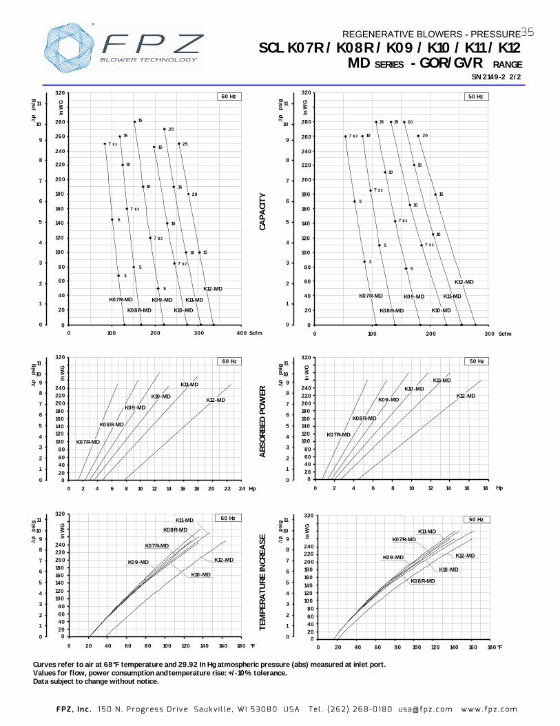
FPZ , In c . 1 50 N . Pr ogr es s Dr ive Sa uk v i l l e , WI 5308 0 USA Tel . (262 ) 26 8-01 80 usa@ fpz .c o m www.fp z .c om
Curves refer to air at 68°F temperature and 29.92 In HgValues for flow, power consumption and temperature rise: +/-10% tolerance. Data subject to change without notice.
CAPA
CITY
A
BSO
RBED
PO
WER
TE
MPE
RATU
RE IN
CREA
SE
SCL K07R / K08R / K09 / K10 / K11 / K12MD SERIES - GOR/GVR RANGE
SN 2149- 2/2
Hp
∆p
psi
g
0 20 40 60 80
100 120 140 160
In W
G
180 200 220 240
320
0 8 10 16 20 4 14 2 6 12 18 0 1
2
3
4
5
6
7
8
9 10
11
K07R-MD
K08R-MD
K09-MD
K10-MD
K11-MD
K12-MD
22 24
60 Hz
0 20 40 60 80
140 160
320
In W
G
200 240
100 120
180 220
Hp0 842 6 10
∆p
psi
g
0
1
2
3
4
5
6
7
8
910
11
12 14 16 18
K07R-MD
K08R-MD
K09-MD
K10-MD K11-MD
K12-MD
50 Hz
020406080
100120140160
240
In W
G
180200220
320
0 20 40 60 80 100 120 140 160 180 °F
50 Hz
K10-MD
K07R-MD K11-MD
K09-MD K12-MD
∆p
psi
g
0
1
2
3
4
5
6
7
8
910
11
K08R-MD
∆p
psi
g
0
1
2
3
4
5
6
7
8
9
10
11
0 100 200 300 Scfm0
20 40 60 80
100
120
140
160
180
In W
G
320
200
220
240
260
280
50 Hz
K08R-MD
K09-MD K07R-MD
K10-MD
K11-MD
7 1/2
15
5
5
7 1/2
7 1/2
10
15 20
15
10
10
7 1/2
3 5
20
15
K12-MD
10
∆p
psi
g
0 1
2
3
4
5
6
7
8
9 10
11
0 20 40 60 80
100 120 140
In W
G
160
320
180 200 220 240
0 20 40 60 80 100 120 140 160 °F 180
K10-MD
K07R-MD
K09-MD
K08R-MD
60 Hz
K12-MD
K11-MD
Scfm
∆p
psi
g
0
1
2
3
4
5
6
7
8
9
10
11
0
20 K08R-MD K07R-MD
5 7 1/2
3 7 1/2
10
5
K09-MD K10-MD
5
7 1/2
60 Hz
400100 200 300 0
15 20
15
10
K11-MD
10
15 7 1/2 25
20
15
K12-MD
15
10
320
40
60
80
100
120
140
180
In W
G
160
240
220
200
260
280
atmospheric pressure (abs) measured at inlet port.
REGENERATIVE BLOWERS - PRESSURE35
2

FPZ , In c . 1 50 N . Pr ogr es s Dr ive Sa uk v i l l e , WI 5308 0 USA Tel . (262 ) 26 8-01 80 usa@ fpz .c o m www.fp z .c om
TECHNICAL CHARACTERISTICS - Aluminium alloy construction - Smooth operation - High efficiency impeller - Maintenance free - Mountable in any position - G1/8” female thread on both
suction and discharge silencer port flanges
OPTIONS - Special voltages (IEC 38) - Surface treatments
ACCESSORIES - Inlet and/or inline filters - Additional inlet/outlet silencers - Safety valves - Flow converting device - Optional connectors
- For proper use, the blower should be equipped wit h inlet filter and safety valve; other accessories a vailable on request. - Ambient temperature from +5° to +104° F. - Specifications subject to change without notice.
Model Maximum
flow Scfm
Installed power
Hp Size
Maximum differential pressure
∆∆∆∆p ( In WG )
Noise level Lp dB (A)
(1)
Weight (2)
60 Hz 50 Hz 60 Hz 50 Hz 60 Hz 50 Hz 3500 rpm 2900 rpm 3500 rpm 2900 rpm 3500 rpm 2900 rpm Lbs
K07-TD 296 245
7 ½ NEMA 182-4TC
90 130 80.9 78.9 156.50 NEMA 213-5TC
10 NEMA 213-5TC 135 185 81.2 79.2 156.50
15 NEMA 213-5TC
225 230
81.8 79.8
156.50 NEMA 254-6TC 160.90
20 NEMA 254-6TC 240 82.1 160.90
K08-TD 368 305
10 NEMA 213 -5TC 95 140 80.4 78.4 169.80
15 NEMA 213-5TC
170 220 81.5 79.5 169.00
NEMA 254-6TC 178.60 20 NEMA 254-6TC 220 240 82.3 80.3 178.60
K09-TD 467 387
15 NEMA 213-5TC
105 155 82.7 80.7 196.20
NEMA 254-6TC 201.70 20 NEMA 254-6TC 160 225 83.0 81.0 201.70 25 NEMA 284-6TSC 220
240 83.3 81.3 198.40
30 NEMA 284-6TSC 240 83.6 81.6 198.40
K10-TD 571 473
15 NEMA 213-5TC
85 130 86.6 84.6 202.80
NEMA 254-6TC 209.50
20 NEMA 254-6TC 130 180 86.9 84.9 209.50 25 NEMA 284-6TSC 180
240 87.2
85.2 205.00
30 NEMA 284-6TSC 200 87.5 205.00
40 NEMA 324-6TSC 240 87.8 220.50
K11-TD 642 532
20 NEMA 254-6TC 90 140 87.4 85.4 246.80
25 NEMA 284-6TSC 130 180 87.9 85.9 244.70 30 NEMA 284-6TSC 150
240 88.4
86.4 244.70
40 NEMA 324-6TSC 240 88.9 264.50
K12-TD 716 593
25 NEMA 284-6TSC 85 140 88.2 86.2 242.5 30 NEMA 284-6TSC 120 190 88.7 86.7 242.5 40 NEMA 324-6TSC 190 240 89,2 87.2 262.3 50 NEMA 324-6TSC 240 - 89.5 - 262.3
(1) Noise measured at 1 m distance with inlet and outlet ports piped, i accordance to ISO 3744. (2) Value is refered to weight of the machine without electric motor
For dimensions, please refer to drw:
SCL K07 / K08 / K09 / K10 / K11 / K12TD SERIES - GOR RANGE
SN 2179-3 1/2
G 1/8”
SI 1971
36 REGENERATIVE BLOWERS - PRESSURE
n

FPZ , In c . 1 50 N . Pr ogr es s Dr ive Sa uk v i l l e , WI 5308 0 USA Tel . (262 ) 26 8-01 80 usa@ fpz .c o m www.fp z .c om
Curves refer to air at 68°F temperature and 29.92 In Hg atmospheric pressure (abs) measured at inlet p ort. Values for flow, power consumption and temperature rise +/-10% tolerance. Data subject to change without notice.
CAPA
CITY
A
BSO
RBED
PO
WER
TE
MPE
RATU
RE IN
CREA
SE
SCL K07 / K08 / K09 / K10 / K11 / K12TD SERIES - GOR RANGE
SN 2179-
0 100 200 300 400 Scfm 500 600
K07-TD
K10-TD K08-TD
K11-TD K09-TD
15
15
10
10
20
20
25
15
15
20
25
0
20
40
60
80
100
120
140
160
180
In W
G
200
220
240
280
30
25 20
0
1
2
3
4
5
6
7
8
9
10
p p
sig
700
K12-TD
25
30
40
50 Hz
7 1/2
0
1
2
3
4
5
6
7
8
9
10
p p
sig
K07-TD K11 -TD
K08-TD
K09-TD
Hp 0 10 20 30
0 20 40 60
80 100
120
220
280
In W
G
140 160
180 200
K10 -TD K12 -TD
40
50 Hz
0
1
2
3
4
5
6
7
8
9
10
p p
sig
0
20
40 60
80
100
120
140
160 180
200 220
280
0 20 40 60 80 100 120 140 160 180 °F
In W
G
K08-TD
K07-TD
K11 -TD
K09-TD
K10 -TD
K12 -TD
50 Hz
K07-TD
K08-TD K10-TD
K09-TD
20 20 15
10
15
40 40 30 25
20
15 20
25 30
30 25
7 1/2 10
15
0
20
40
60
80
100
120
140
180
In W
G
160
200
220
240
260
300
100 200 300 500 Scfm 400 600 700
20
p
psig
0
1
2
3
4
5
6
7
8
9
10
800
25
30
40
50
K12 -TD
K11 -TD
60 Hz
0 20 40 60 80 100 120 140 160 °F 180
p
psig
0 1
2
3
4
5
6
7
8
9
10
K08-TD
K07-TD
K11 -TD
K09-TD
K10 -TD
0 20 40 60 80
100 120 140
200
In W
G
160 180
220 240
300
K12 -TD
60 Hz
0
20 40 60 80
100 120 140 160
In W
G
180 200 220 240
300
Hp 0 10 20 30 40
K11 -TD
K08-TD
K09-TD K07-TD
0 1
2
3
4
5
6
7
8
9
10
50
K10 -TD K12 -TD
60 Hz
p
psig
REGENERATIVE BLOWERS - PRESSURE37
3 2/2

FPZ , In c . 1 50 N . Pr ogr es s Dr ive Sa uk v i l l e , WI 5308 0 USA Tel . (262 ) 26 8-01 80 usa@ fpz .c o m www.fp z .c om
Model Maximum
flow cfm
Installed power
Hp
Maximum differential pressure
∆p ( In Hg )
Noise level Lp dB (A)
(1)
Overall dimensions
H Weight
60 Hz 50 Hz 60 Hz 50 Hz 60 Hz 50 Hz 60 Hz 50 Hz 3500 rpm 2900 rpm 3500 rpm 2900 rpm 3500 rpm 2900 rpm 3500 rpm 2900 rpm Inches Lbs
3/4 3/4 4.7 3.7 61.0 59.0 10.43 24.3 K03-MS 52 43 1 1 5.9 4.9 61.3 59.3 12.0
1 ½ 1 ½ 4.3 5.9 63.8 61.8 11.65 2 2 6.3 6.6 64.0 62.0 13.78 48.0 K04-MS 98 81 3 - 7.4 - 64.2 - 13.78 52.5 2 2 3.8 5.1 69.5 67.5 13.20 56.7 3 3 6.6 7.1 69.8 67.8 13.20 60.6 K05-MS 156 129 4 - 8.1 - 70.1 - 14.40 77.2 3 3 3.7 4.8 72.0 70.0 13.8 4 4 5 7.0 72.3 70.3 14.17 82.5
5 ½ 5 ½ 8.1 8.1 72.6 70.6 15.5 K06-MS 216 179
6 1/5 - - 72.9 - 1
(1) Noise measured at 1 m distance with inlet and outlet ports piped, in accordance to ISO 3744.
SCL K03 / K04 / K05 / K06
SN 1879-11B 1/2
- For proper use, the blower should be equipped with inlet filter an - Ambient temperature rom +5° to +104°F. - Specifications subject to change without notice.
e
a
fIG
d
c
b
s
p1
o
Ømn r q
z
H
3x120°øu
t
Accessory
Model a b c d e f G I m n o p1 q r s t u z
K03-MS 9.49 10.55 5.79 1.69 9.06 8.07 1” ¼ NPT 3.39 0.39 3.27 5.59 8.07 0.71 2.95 0.16 M6 5.51 0.47 K04-MS 11.22 12.40 6.77 1.93 10.04 8.86 1"1/2
K05-MS 12.87 14.37 7.87 2.13 12.60 10.24 2” NPT 4.72 0.59 4.53 10.43 12.60 0.71 3.86 0.16 M8 7.87 0.75 K06-MS 14.80 15.47 8.07 2.13 12.80 11.42 0.59 5.51 10.71 13.15 0.71 3.35 0.16 M8 9.45 0.75
TECHNICAL CHARACTERISTICS - Aluminium alloy construction - Smooth operation - High efficiency impeller - Maintenance free - Mountable in any position - Recognized TEFC - cURus motor
OPTIONS - Special voltages (IEC 38) - Surface treatments
ACCESSORIES - Inlet and/or inline filters - Additional inlet/outlet silencers - Safety valves - Flow converting device - Optional connectors
Dimensions in inches. Dimension for reference only.
SERIES
4.02 0.47 3.74 6.73 8.74 0.71 2.76 0.16 M6 6.89 0.71 NPT
2 ” NPT 4.92
d safety valve; other accessories available on request. f
REGENERATIVE BLOWERS - VACUUM
32.0
40.3
69.0
5.85.3
2.
MS
8.9 6.3 9 5
38

FPZ , In c . 1 50 N . Pr ogr es s Dr ive Sa uk v i l l e , WI 5308 0 USA Tel . (262 ) 26 8-01 80 usa@ fpz .c o m www.fp z .c om
CAPA
CITY
A
BSO
RBED
PO
WER
TEM
PERA
TURE
INCR
ESA
SCL K03 / K04 / K05 / K06
SN 1879-1 B 2/2
Curves refer to air at 68° F temperature, measured at Values for flow, power consumption and Data subject to change without notice.
p
In H
g
0
1
2
3
4
5
6
7
8
9
10
2
3
4
K05-MS
0
20
40
60
80
100
120
140
0 50 100 150 200 250
In W
G 60 Hz
cfm
6 1/5
5 1/2
4
3
K06-MS K04-MS
1 1/2
2
3
K03-MS
3/4
1
0
1
2
3
4
5
6
7
8
9
10
p
In H
g
0
20
40
60
80
100
140
0 1 2 3 4 5 6 7 Hp
In W
G 60 Hz
K05-MS
K06-MS
K04-MS
K03-MS
p
In H
g
0
1
2
3
4
5
6
7
8
9
10
0 20 40 60 80 100 120 140 160 180 200 °F
0
20
40
60
80
100
140
In W
G 60 Hz
K06-MS
K04-MS K05-MS
K03-MS
p
In H
g
0
1
2
3
4
5
6
7
8
2
3
K05-MS
0
20
40
60
80
100
120
0 50 100 150 200 cfm
In W
G 50 Hz
5 1/2
3
K06-MSK04-MS
2
1 1/2
K03-MS
3/4
4
1
p
In H
g
0
1
2
3
4
5
6
7
8
0
20
40
60
80
120
In W
G
K05-MS
0 1 2 3 4 5 Hp
50 Hz
K06-MS
K04-MS
K03-MS
p
In H
g
0
1
2
3
4
5
6
7
8
0
20
40
60
80
120
0 20 40 60 80 100 120 140 160 180 200 °F
50 Hz
In W
G
K05-MSK04-MS
K03-MS
K06-MS
MS SERIES
SE
REGENERATIVE BLOWERS - VACUUM
temperature rise: +/-10% tolerance. inlet port and 29.92 In Hg atmospheric back pressure (abs).
1
39
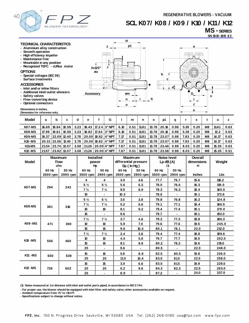
FPZ , In c . 1 50 N . Pr ogr es s Dr ive Sa uk v i l l e , WI 5308 0 USA Tel . (262 ) 26 8-01 80 usa@ fpz .c o m www.fp z .c om
TECHNICAL CHARACTERISTICS - Aluminium alloy construction- Smooth operation - High efficiency impeller - Maintenance free - Mountable in any position - Recognized TEFC - cURus motor
OPTIONS - Special voltages (IEC 38) - Surface treatments
ACCESSORIES - Inlet and/or inline filters - Additional inlet/outlet silencers - Safety valves - Flow converting device - Optional connectors
- For proper use, the blower should be equipped with inlet filter and safety valve; other accessories available on request. - Ambient temperature from +5° to +104°F. - Specifications subject to change without notice.
Model Maximum
flow cfm
Installed power
Hp
Maximum differential pressure
Dp ( In Hg )
Noise level Lp dB (A)
(1)
Overall dimensions
H Weight
60 Hz 50 Hz 60 Hz 50 Hz 60 Hz 50 Hz 60 Hz 50 Hz 3500 rpm 2900 rpm 3500 rpm 2900 rpm 3500 rpm 2900 rpm 3500 rpm 2900 rpm Inches Lbs
K07-MS 294 243
4 4 3.0 4.6 77.7 75.7 15.6 116.25 ½ 5 ½ 5.6 6.3 78.0 76.0 16.3 119.0 7 ½ 7 ½ 8.9 8.9 78.3 76.3 18.4 160.5 10 - 10.3 - 78.6 - 19.1 172.6
K08-MS 381 316
5 ½ 5 ½ 3.0 3.8 78.8 76.8 16.3 124.8 7 ½ 7 ½ 5.2 6.6 79.1 77.1 18.4 166.5 10 10 8.1 9.2 79.4 77.4 19.1 179.0 15 - 9.6 - 79.7 - 19.1 192.0
K0
9-MS 471
390
7 ½ 7 ½ 3.7 4.6 79.3 77.3 18.8 186.3 10 10 5.9 7.0 79.6 77.6 19.5 245.015 15 9.6 10.4 80.1 78.1 22.0 212.0
K10 -MS 556 460
7 ½ 7 ½ 2.4 3.8 79.4 77.4 18.8 189.6 10 10 4.4 5.9 79.7 77.7 19.5 202.015 15 8.1 9.9 80.2 78.2 19.6 215.0 20 - 9.6 - 80.5 - 22.0 248.0
K11 -MS 650
539 15 15 5.9 8.9 82.5 80.5 19.8 226.0
20 20 11.0 10.4 83.0 81.0 22.5 259.0
K12 -MS 726 602 15 15 3.0 6.6 83.5 81.5 19.9 229.5 20 20 6.2 9.6 84.3 82.3 22.5 263.0 25 - 8.9 - 87.2 - 2 4.0 3 . 037
(1) Noise measured at 1 m distance with inlet and outlet ports piped, in accordance to ISO 3 744.
SCL K07/ K08 / K09 / K10 / K11 / K12 SERIES MS -
SN 1810 1/2 -18B
Dimensions in inches. Dimension for reference only.
Model a b c d e f G I m n o p1 q r s t u z
K07-MS 16.69 18.84 10.59 3.23 18.43 17.2 4 3” NPT 6.10 0.51 11.81 13.78 20.16 0.98 5.39 0.20 M8 11.61 0.63 K08-MS 17.99 19.61 10.59 3.23 18.82 17.64 3” NPT 6.10 0.51 11.81 13.78 20.16 0.98 5.39 0.20 M8 12.2 0.63 K09-MS 19.37 22.09 12.40 3.78 20.00 18.82 4” NPT 7.17 0.51 11.81 13.78 23.07 0.98 7.83 0.20 M8 14.17 0.63 K1 0-MS 20.31 22.56 12.40 3.78 20.00 18.82 4” NPT 7.17 0.51 11.81 13.78 23.07 0.98 7.83 0.20 M8 14.17 0.63 K11 -MS 21.34 23.74 13.07 3.58 21.26 20.00 4” NPT 7.87 0.51 11.81 13.78 23.46 0.98 8.03 0.20 M8 15.35 0.63 K1 2-MS 21.57 23.82 13.07 3.58 21.26 20.00 4” NPT 7.87 0.51 11.81 13.78 23.58 0.98 8.03 0.20 M8 15.35 0.51
Accessory
r q
p1 H
o
n
øm
3x120° øu
z
t
G
d
c b
e
f
I
a
s
REGENERATIVE BLOWERS - VACUUM40

FPZ , In c . 1 50 N . Pr ogr es s Dr ive Sa uk v i l l e , WI 5308 0 USA Tel . (262 ) 26 8-01 80 usa@ fpz .c o m www.fp z .c om
Curves refer to air at 68° F temperature, measured at inlet port and 29.92 In Hg atmospheric backpressure (abs). Values for flow, power consumption and temperature rise: +/ -10% tolerance.Data subject to change without notice.
CAPA
CITY
A
BSO
RBED
PO
WER
TE
MPE
RATU
RE IN
CRES
ASE
SCL K07 / K08 / K09 / K10 / K11 / K12 MS SER IES SN 1810-18B 2/2
10
7 1/2
10
2015
10
15
10
K07-MS
4
7 1/2
K10 -MS
7 1/2
K08-MS
7 1/2
K09-MS
5 1/2
5 1/2
K12 -MS
0
20
40
60
80
100
120
140
160
0 100 200 300 400 500 600
In W
G
800 cfm 700
50 Hz 60 Hz
20
15
0
1
2
3
4
5
6
7
8
9
10
11
p
In
Hg
0
1
2
3
4
5
6
7
8
9
10
11
p
In
Hg
0
20
40
60
80
100
120
160
0 5 10 15 Hp
In W
G
20
50 Hz
K08-MS
K07-MS K11 -MS K09-MS
K10 -MS K12 -MS
0
1
2
3
4
5
6
7
8
9
10
11
p
In
Hg
0
20
40
60
80 100
120
160
0 20 40 60 80 100 120 140 160 °F
K10 -MS
K07-MS
K08-MS
K11 -MS
50 Hz
In W
G
K09-MS
K12 -MS
0
1
2
3
4
5
6
7
8
9
10
11
p
In
Hg
0
20
40
60
80
100
120
140
160
0 100 200 300 400 500 700 cfm
In W
G
600
K07-MS
K10 -MS K08-MS
K11 -MS K09-MS
K12 -MS
4
7 1/2
7 1/2
10
15 10
7 1/2
20
15
15
10
7 1/2
5 1/2
5 1/2
15
20
50 Hz
25
0
1
2
3
4
5
6
7
8
9
10
11
p
In
Hg
K07-MS
K10 -MS
0
20
40
60
80
100
120
160
0 5 10 15 20 Hp
In W
G
K08-MS
60 Hz
25
K09-MS K12 -MS
0
1
2
3
4
5
6
7
8
9
10
11
p
In
Hg
In W
G
0
20
40
60
80
100
120
160
0 20 40 60 80 100 120 140 160 180 200 °F
60 Hz
K11-MS
K08-MS
K10 -MS
K09-MS
K12 -MS
REGENERATIVE BLOWERS - VACUUM
15
K07-MS
20
15
K11 -MS
15
K11 -MS
41
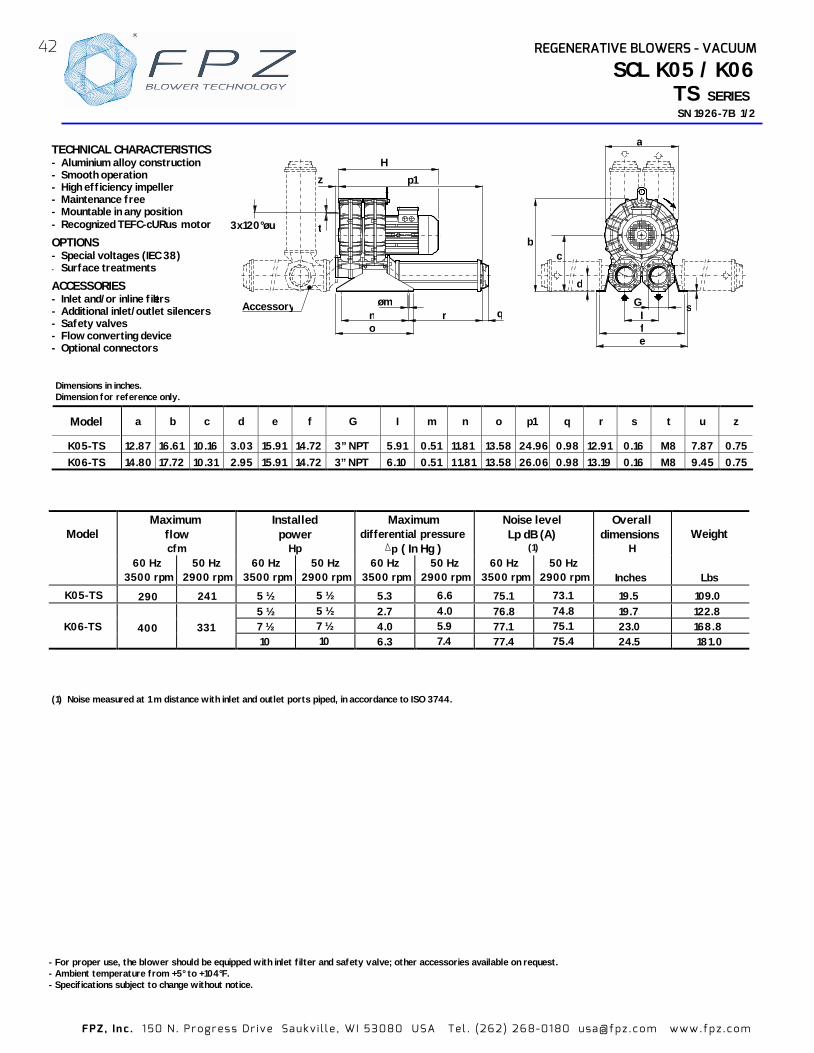
FPZ , In c . 1 50 N . Pr ogr es s Dr ive Sa uk v i l l e , WI 5308 0 USA Tel . (262 ) 26 8-01 80 usa@ fpz .c o m www.fp z .c om
Model Maximum
flow cfm
Installed power
Hp
Maximum differential pressure
p ( In Hg )
Noise level Lp dB (A)
(1)
Overall dimensions
H Weight
60 Hz 50 Hz 60 Hz 50 Hz 60 Hz 50 Hz 60 Hz 50 Hz 3500 rpm 2900 rpm 3500 rpm 2900 rpm 3500 rpm 2900 rpm 3500 rpm 2900 rpm Inches Lbs
K05
-TS 290
241
5 ½ 5 ½ 5.3 6.6 75.1 73.1 19.5 109.0
K06-TS 400 331 5 ½ 5 ½ 2.7 4.0 76.8 74.8 19.7 122.87 ½ 7 ½ 4.0 5.9 77.1 75.1 23.0 168.810 10 6.3 7.4 77.4 75.4 24.5 181.0
SCL K05 / K06TS SERIES SN 192 1/2 6-7B
- For proper use, the blower should be equipped with inlet filter and safety v alve; other accessories available on request.- Ambient temperature from +5° to +104°F. - Specifications subject to change without notice.
s G
e f I
d
c b
a
r o n
øm q
3x120°øu t
z H
p1
Accessory
(1) Noise measured at 1 m distance with in and outlet ports piped, in accordance to ISO 3744. let
TECHNICAL CHARACTERISTICS - Aluminium alloy construction - Smooth operation - High efficiency impeller - Maintenance free - Mountable in any position - Recognized TEFC-cURus motor
OPTIONS - Special voltages (IEC 38) - Surface treatments
ACCESSORIES - Inlet and/or inline filters - Additional inlet/outlet silencers - Safety valves - Flow converting device - Optional connectors
42 REGENERATIVE BLOWERS - VACUUM
Model a b c d e f G I m n o p1 q r s t u z
K05-TS 12.87 16.61 10.16 3.03 15.91 14.72 3” NPT 5.91 0.51 11.81 13.58 24.96 0.98 12.91 0.16 M8 7.87 0.75 K06-TS 14.80 17.72 10.31 2.95 15.91 14.72 3” NPT 6.10 0.51 1 1.81 13.58 26.06 0.98 13.19 0.16 M8 9.45 0.75
Dimensions in inches. Dimension for reference only.

FPZ , In c . 1 50 N . Pr ogr es s Dr ive Sa uk v i l l e , WI 5308 0 USA Tel . (262 ) 26 8-01 80 usa@ fpz .c o m www.fp z .c om
CAPA
CITY
A
BSO
RBED
PO
WER
TE
MPE
RATU
RE
INCR
EASE
SCL K05 / K06TS SERIESSN 192
6-7B 2/2
Curves refer to air at 68° F temperature, measured at inlet port and 29.92 In Hg atmospheric backpressure (abs). Values for flow, power consumption and temperature rise: +/ 10% tolerance. -Data subject to change without notice.
5 1/2
60 Hz
10
0 100 200 300 400 500 cfm 0
20
40
60
80
100
K06-TS
7 1/2
5 1/2
K05-TS
p
In
Hg
0
1
2
3
4
5
6
7
p
In
Hg
0
1
2
3
4
5
6
7
8
20
40
60
80
100
120
0 50 100 150 200 250 300 350 4000
cfm
50 Hz
In W
G
10
K06-TS
5 1/2
7 1/2
K05-TS
5 1/2
p
In
Hg
0
1
2
3
4
5
6
7
0
20
40
60
80
100
In W
G
0 20 40 60 80 100 °F
60 Hz
K05-TS
K06-TS
60 Hz
K06-TS
0
20
40
60
80
100
0 1 2 3 4 5 6 7 8 Hp
In W
G
9 10
K05-TS
p
In
Hg
0
1
2
3
4
5
6
7
0
20
40
60
80
120
0 1 2 3 4 5 6 7 8 Hp
In W
G
K05-TS
K06-TS
9 10
50 Hz
50 Hz
0
20
40
60
80
120
0 20 40 60 80 100 120 140 160 °F
In W
G
K06-TS K05-TS
p
In
Hg
0
1
2
3
4
5
6
7
8
p
In
Hg
0
1
2
3
4
5
6
7
8
43REGENERATIVE BLOWERS - VACUUM

44
Dimensions in inches. Dimension for reference only.
TECHNICAL CHARACTERISTICS - Aluminium alloy construction - Smooth operation - High efficiency impeller - Maintenance free - Mountable in any position - Recognized TEFC-cURus motor- G1/8” female thread on both suction
and discharge silencer port flanges
OPTIONS - Special voltages (IEC 38) - Surface treatments
ACCESSORIES - Inlet and/or inline filters - Additional inlet/outlet silencers - Safety valves - Flow converting device - Optional connectors
s G
e f I
d
c b
a
For model K11-K12-TS Hp 30 60Hz only
Accessory
t
r o
n n øm
q
z H
p1
3x120°øu
60 Hz3500 rpm
50 Hz2900 rpm
60 Hz3500 rpm
50 Hz2900 rpm
60 Hz3500 rpm
50 Hz2900 rpm
60 Hz3500 rpm
50 Hz2900 rpm
7 ½ 7 ½ 2.6 4.4 83.9 81.9 23.0 218.3
10 10 4.4 6.6 84.2 82.2 24.5 230.4
15 15 8.1 8.1 84.8 82.8 24.5 243.7
K08-TS 715 592 15 15 4.4 6.4 83.3 81.3 24.5 256.0
20 20 5.9 7.4 85.0 83.0 31.0 422.0
25 25 8.1 8.8 87.0 85.0 31.0 432.0
20 20 4.4 5.9 88.1 86.1 31.0 429.0
25 25 5.9 7.4 88.4 86.4 31.0 439.0
25 25 3.4 6.6 89.4 87.4 31.5 469.0
30 30 5.1 8.1 90.0 88.0 31.5 475.0
K12-TS 1410 1168 30 30 3.3 5.9 90.6 88.6 32.0 475.0
K11-TS 1254 1039
Installed power HpMaximum
diff erential pressure∆p ( In Hg)
K10-TS 1093 906
K07-TS 588 487
K09-TS 941 780
WeightLbs
Model
Maximum flow Noise level Lp dB (A)
(1) Overall dimensions H
Inches
cfm
1/8” gauge port
FPZ , In c . 1 50 N . Pr ogr es s Dr ive Sa uk v i l l e , WI 5308 0 USA Tel . (262 ) 26 8-01 80 usa@ fpz .c o m www.fp z .c om
(1) Noise measured at 1 m distance with inlet and outlet ports piped, in accordance to ISO 3744. (2) K11-K12-TS Hp 30 vertical assembly only.
- For proper use, the blower should be equipped with inlet filt- Ambient temperature from +5° to +104°F. - Specifications subject to change without notice.
er and safety valve; other accessories available on request.
SERIES TS SN 1826-14
REGENERATIVE BLOWERS VACUUM
SCL K07 / K08 / K09 / K10 / K11 / K12
B
Model a b c d e f G l m n o p1 q r s t u z
K07-TS 16.69 20.91 12.56 3.86 18.50 17.24 4" NPT 7.17 0.51 9.84 21.65 31.57 0.98 11.77 0.20 M8 11.61 0.63
K08-TS 17.99 21.57 12.56 3.86 18.90 17.64 4" NPT 7.17 0.51 9.84 21.65 31.57 0.98 11.77 0.20 M8 12.20 0.63
K09-TS 19.37 24.02 14.37 4.41 20.08 18.82 5" NPT 8.27 0.51 9.84 21.65 33.46 1.38 12.40 0.20 M8 14.17 0.63
K10-TS 20.31 24.53 14.37 4.41 20.08 18.82 5" NPT 8.27 0.51 9.84 21.65 33.46 1.38 12.40 0.20 M8 14.17 0.63
K11-TS 21.34 25.59 14.96 4.17 21.26 20.00 5" NPT 8.98 0.51 9.84 21.65 34.25 1.38 12.60 0.20 M8 15.35 0.63
K12-TS 21.57 25.71 14.96 4.17 21.26 20.00 5" NPT 8.98 0.51 9.84 21.65 34.8 1.38 12.60 0.20 M8 15.4 0.63
44

FPZ , In c . 1 50 N . Pr ogr es s Dr ive Sa uk v i l l e , WI 5308 0 USA Tel . (262 ) 26 8-01 80 usa@ fpz .c o m www.fp z .c om
CAPA
CITY
A
BSO
RBED
PO
WER
TE
MPE
RATU
RE IN
CRES
ASE
SERIES
Curves refer to air at 68° F temperature, measured at inlet port and 29.92 In Hg atmospheric backpressure (abs). Values for flow, power consumption and Data subject to change without notice.
0
1
2
3 4
5
6
7
8
9
10
p
In
Hg
K07-TS
K08-TS
K09-TS
K10-TS K11-TS
0
20
40
60
80
100
140
0 2 4 6 8 10 12 14 16 18 20 22 24 26 28 30 Hp
60 Hz
In W
G
K12-TS
0
1
2
3 4
5
6
7
8
9
10
p
In
Hg
0
20
40
60
80
100
140
0 20 40 60 80 100 120 °F
In W
G 60 Hz
K10-TS
K08-TS
K07-TS
K09-TS
K11-TS
K12-TS
0
1
2
3
4
5
6
7
8
9
10
p
In
Hg
In W
G
25
20
0
20
40
60
80
100
120
140
200 400 600 800 1000 1200 1400
K08-TS
15
15
10
7 1/2
K07-TS
K09-TS
20
25
K10-TS
K11-TS
25
30
30
K12-TS
1600 cfm
60 Hz
0
1
2
3
4
5
6
7
8
9
10
p
In
Hg
K10-TS
0
20
40
60
80
100
120
140
0 200 400 600 800 1000 1200 cfm
50 Hz
In W
G
K08-TS
K07-TS
K09-TS
K11-TS
25
20
15
15
10
7 1/2
20
25
25
30
30
0
1
2
3 4
5
6
7
8
9
10
p
In
Hg
K07-TS
K08-TS
K09-TS
K10-TS K11-TS
0
20
40
60
80
100
140
0 2 4 6 8 10 12 14 16 18 20 22 24 26 Hp
50 Hz
In W
G
K12-TS
0
1
2
3 4
5
6
7
8
9
10
p
In
Hg
0
20
40
60
80
100
140
0 20 40 60 80 100 120 140 160 180 200 °F
50 Hz
In W
G
K10-TS
K09-TS
K07-TS
K08-TS
K11-TS
K12-TS
K12-TS
TS SN 1826-1 B
45REGENERATIVE BLOWERS - VACUUM
temperature rise: +/-10% tolerance.
SCL K07 / K08 / K09 / K10 / K11 / K12
4

Model a b c d e f G l m n o p1 q r s t u z
K07R-MD 16.69 18.94 10.59 3.23 18.43 17.24 2” NPT 6.10 0.51 11.81 31.78 16.46 0.71 1.70 0.20 M8 11.61 0.63
K08R-MD 17.99 19.61 10.59 3.23 18.82 17.64 2” NPT 6.10 0.51 11.81 13.78 16.46 0.71 1.70 0.20 M8 12.20 0.63
K09-MD 19.37 22.09 12.40 3.78 20.00 18.82 4” NPT 7.17 0.51 11.81 13.78 25.35 0.98 10.12 0.20 M8 14.17 0.63
K10-MD 20.31 22.56 12.40 3.78 20.00 18.82 4” NPT 7.17 0.51 11.81 13.78 25.35 0.98 10.12 0.20 M8 14.17 0.63
K11-MD 21.35 23.74 13.07 3.58 21.18 20.00 4” NPT 7.87 0.51 11.81 13.78 25.75 0.98 .20 M8 15.35 0.63
K12-MD 21.57 23.85 13.07 3.58 21.18 20.00 4” NPT 7.87 0.51 11.81 13.78 25.87 0.98 10.31 0.20 M8 15.35 0.62
SN 1852-1 B 1/2MD SERIES
SCL K07R / K08R / K09 / K10 / K11 / K12
REGENERATIVE BLOWERS - VACUUM
FPZ , In c . 1 50 N . Pr ogr es s Dr ive Sa uk v i l l e , WI 5308 0 USA Tel . (262 ) 26 8-01 80 usa@ fpz .c o m www.fp z .c om
(1) Noise measured at 1 m distance with inlet and outlet ports piped, in accordance to ISO 3744.
- For proper use, the blower should be equipped with inlet filter - Ambient temperature from +5° to +104°F. - Specifications subject to change without notice.
and safety valve; other accessories available on request.
TECHNICAL CHARACTERISTICS - Aluminium alloy construction - Smooth operation - High efficiency impeller - Maintenance free - Mountable in any position - Recognized TEFC - cURus motor
OPTIONS - Special voltages (IEC 38) - Surface treatments
ACCESSORIES - Inlet and/or inline filters - Additional inlet/outlet silencers - Safety valves - Flow converting device - Optional connectors
Dimensions in inches. Dimension for reference only.
a
b
c
d
e f I
G s
n o
r q øm
H p1
3x120° øu
t
z
60 Hz3500 rpm
50 Hz2900 rpm
60 Hz3500 rpm
50 Hz2900 rpm
60 Hz3500 rpm
50 Hz2900 rpm
60 Hz3500 rpm
50 Hz2900 rpm
5 ½ 5 ½ 11.8 13.3 74.5 72.5 16.30 1177 ½ 7 ½ 13.3 75.0 73.0 17.60 1595 ½ 5 ½ 7.4 11.8 76.2 74.2 16.30 1257 ½ 7 ½ 11.9 13.3 76.6 74.6 17.60 16710 10 13.3 - 77.0 75.0 19.10 179
K09-MD 221 183 10 10 14.0 11.8 79.5 77.5 19.50 21010 10 9.6 12.6 80.3 78.3 19.50 21415 15 12.6 - 81.4 79.4 19.50 228
K11-MD 306 254 15 15 13.3 12.6 81.4 79.4 19.70 24415 15 7.4 12.6 82.3 80.3 19.90 24220 20 12.6 - 82.6 80.6 22.50 278
WeightLbs
Model
Maximum flow cfm
Noise level Lp dB (A)(1)
Overall dimensions
HInches
K10-MD 275 228
K07R-MD 129 107
K08R-MD 168 139
K12-MD 336 278
Installed power HpMaximum
diff erential pressure∆p ( In Hg )
-
0.31 0 1
1
46
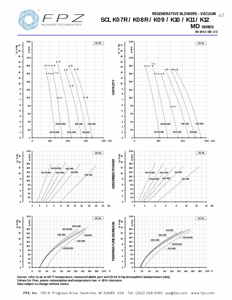
FPZ , In c . 1 50 N . Pr ogr es s Dr ive Sa uk v i l l e , WI 5308 0 USA Tel . (262 ) 26 8-01 80 usa@ fpz .c o m www.fp z .c om
CAPA
CITY
A
BSO
RBED
PO
WER
TE
MPE
RATU
RE IN
CREA
SE
0 20 40 60 80 100 120 140 160 180 200 °F
SCL K07R / K08R / K09 / K10 / K11 / K12
SN 1852
Curves refer to air at 68° F temperature, measured at inlet port and 29.92 In Hg atmospheric backpressure (abs). Values for flow, power consumption and Data subject to change without notice.
cfm
p I
n Hg
0 1
2
3
4
5
6
7
8
9
10
11
12
13
14
15
16
17
15
10
K10-MD
0
20
40
60
80
100
120
140
160
180
200
240
0 100 200 300 400
60 Hz
In W
G
K08R-MD
5 1/2
7 1/2
10
K07R-MD
7 1/2
K09-MD
10
15
K11-MD
5 1/2
15
20
K12-MD
cfm
240
p
In
Hg
0 1
2
3
4
5
6
7
8
9
10
11
12
13
14
15
16
17
In W
G
K10-MD
0
20
40
60
80
100
120
140
160
180
200
0 100 200 300
50 Hz
K08R-MD
K07R-MD K09-MD K11-MD
10 5 1/2
7 1/2
10
15
5 1/2
5 1/2
K12-MD
15
0 2
4
6
8
10
12
14
16
p I
n Hg
0
20
40
60
80
100
120
140
160
180
240
0 2 4 6 8 10 12 14 20 Hp
In W
G
16 18
60 Hz
K07R-MD
K08R-MD
K09-MD K11-MD K12-MD
K10-MD
0 2
4
6
8
10
12
14
16
p I
n Hg
0 20 40 60
80
100
120
140 160 180
240
K10-MD
60 Hz
In W
G
K08R-MD
K07R-MD K09-MD
K12-MD
K11-MD
0 2
4
6
8
10
12
14
16
p I
n Hg
0
20
40
60
80
100
120
140 160 180
240
0 20 40 60 80 100 120 140 160 180 200
K10-MD
In W
G
°F
50 Hz
K08R-MD
K07R-MD K09-MD
K11-MD
K12-MD
0 2
4
6
8
10
12
14
16
p I
n Hg
0
20
40
60
80
100
120
140
160
180
240
0 2 4 6 8 10 12 Hp
In W
G
14
50 Hz
K07R-MD
K08R-MD
K09-MD K11-MD
K12-MD
K10-MD
MD SERIES
REGENERATIVE BLOWERS - VACUUM
temperature rise: +/-10% tolerance.
-11B 2/2
47
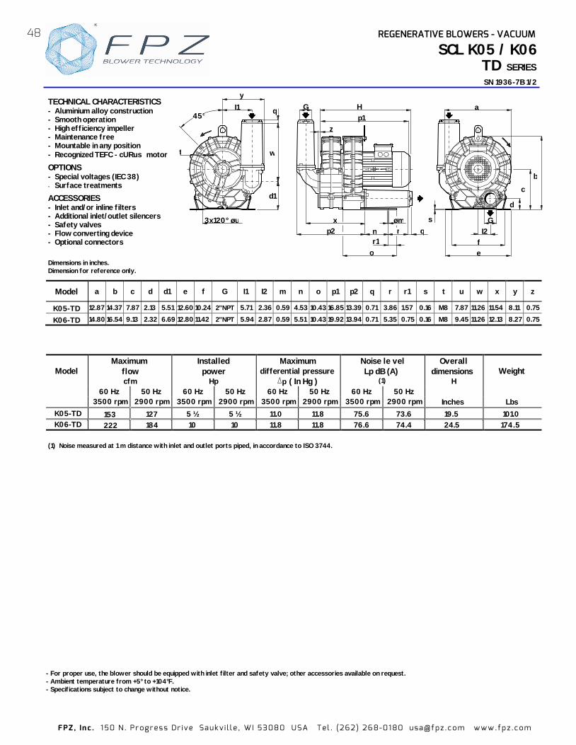
FPZ , In c . 1 50 N . Pr ogr es s Dr ive Sa uk v i l l e , WI 5308 0 USA Tel . (262 ) 26 8-01 80 usa@ fpz .c o m www.fp z .c om
Model Maximum
flow cfm
Installed power
Hp
Maximum differential pressure
p ( In Hg )
Noise le vel Lp dB (A)
(1)
Overall dimensions
H Weight
60 Hz 50 Hz 60 Hz 50 Hz 60 Hz 50 Hz 60 Hz 50 Hz 3500 rpm 2900 rpm 3500 rpm 2900 rpm 3500 rpm 2900 rpm 3500 rpm 2900 rpm Inches Lbs
K05-TD
153
127
5 ½ 5 ½ 11.0 11.8 75.6 73.6 1 9.5 101.0K06-TD 222
184 10 10 11.8 11.8 76.6 74.4 24.5 174.5
- For proper use, the blower should be equipped with inlet filter and safety valve; other accessories available on request. - Ambient temperature from +5° to +104°F. - Specifications subject to change without notice.
(1) Noise measured at 1 m distance with inlet and outlet ports piped, in accordance to ISO 3744.
SN 193 1/2 6-7B
a
d
b
c
s
e f
I2 G
t
3x120° øu
y I1 q
d1
w
45°
Model a b c d d1 e f G I1 I2 m n o p1 p2 q r r1 s t u w x y z
K05-TD 12.87 14.37 7.87 2.13 5.51 12.60 10.24 2” NPT 5.71 2.36 0.59 4.53 10.43 16.85 13.39 0.71 3.86 1.57 0.16 M8 7.87 11.26 11.54 8.11 0.75
K06-TD 14.80 16.54 9.13 2.32 6.69 12.80 11.42 2” NPT 5.94 2.87 0.59 5.51 10.43 19.92 13.94 0.71 5.35 0.75 0.16 M8 9.45 11.26 12.13 8.27 0.75
Dimensions in inches. Dimension for reference only.
G p1 H
z
q
o
p2 x
n r øm
r1
TECHNICAL CHARACTERISTICS - Aluminium alloy construction- Smooth operation - High efficiency impeller - Maintenance free - Mountable in any position - Recognized TEFC - cURus motor
OPTIONS - Special voltages (IEC 38) - Surface treatments
ACCESSORIES - Inlet and/or inline filters - Additional inlet/outlet silencers - Safety valves - Flow converting device - Optional connectors
48 REGENERATIVE BLOWERS - VACUUM
SCL K05 / K06TD SERIES

FPZ , In c . 1 50 N . Pr ogr es s Dr ive Sa uk v i l l e , WI 5308 0 USA Tel . (262 ) 26 8-01 80 usa@ fpz .c o m www.fp z .c om
CAPA
CITY
A
BSO
RBED
PO
WER
TE
MPE
RATU
RE
INCR
EASE
Curves refer to air at 68° F temperature, measured at inlet port and 29.92 In Hg atmospheric backpressure (abs). Values for flow, power consumpti -10% tolerance. on and temperature rise: +/Data subject to change without notice.
K04 / K05 / K06 SCL TD SERIES
SN 193 2/2 6-7B
cfm
0
20
40
60
80
100
120
140
160
180
0 50 100 150 200
50 Hz
5 1/2 10
K06-TD
K05-TD
p I
n Hg
0
1
2
3
4
5
6
7
8
9
10
11
12
13
5 1/2
0
20
40
60
80
100
120
140
160
180
0 50 100 150 200 250 cfm
60 Hz
In W
G
10
K05-TD K06-TD
p I
n Hg
0 1
2 3
4
5
6
7
8 9
10
11
12
13
K06-TD
60 Hz
0
20
40
60
80
100
120
140
180
In W
G
0 1 2 3 4 5 6 7 8 Hp 9
K05-TD
p I
n Hg
0 1
2 3
4
5
6
7
8 9
10
11
12
13
0
20
40
60
80
100
120
140
180
In W
G
0 1 2 3 4 5 6 7 Hp
K06-TD
50 Hz
K05-TD
0
20
40
60
80
100
120
140
180
0 20 40 60 80 100 120 140 160 180
50 Hz
In W
G
°F
K05-TD
K06-TD
0
20
40
60
80
100
120
140
180
In W
G
0 20 40 60 80 100 120 140 160 180 °F
60 Hz
K05-TD
K06-TD
p
In H
g
0
1
2
3
4
5
6
7
8
9
10
11
12
13
p I
n Hg
0 1
2 3
4
5
6
7
8 9
10
11
12
13
p I
n Hg
0 1
2 3
4
5
6
7
8 9
10
11
12
13
REGENERATIVE BLOWERS - VACUUM 49

Model Maximum
flow cfm
Installed power
Hp
Maximum differential pressure
∆∆∆∆p ( In Hg )
Noise level Lp dB (A)
(1)
Overall dimensions
H Weight
60 Hz 50 Hz 60 Hz 50 Hz 60 Hz 50 Hz 60 Hz 50 Hz 3500 rpm 2900 rpm 3500 rpm 2900 rpm 3500 rpm 2900 rpm 3500 rpm 2900 rpm Inches Lbs
K07-TD 296 245 15 15 12.6 11.8 79.5 77.5 24.5 234.8K08-TD 368 305
15 15 12.6 12.6 79.9 77.9 24.5 248.5
K09-TD 467 387 25 - 14.0 82.8 - 30.0K10-TD 571 473
25 25 13.3 13.3 86.5 84.5 30.0
K11-TD 642 532 25 25 9.6 12.6 87.2 85.2 30.5 4 .K12-TD 716 593
30 30 1 88.0 86.0 31.0 443.0
(1) Noise measured at 1 m dis
SERIES
Model a b c d d1 e f G I1
K07-TD 16.69 18.94 10.59 3.23 7.56 18.43 17.24 3”NPT 7.36 3.05 0.51 11.81 13.78 25.55 15.43 0.98 5.39 0.20 M8 11.61 18.94 12.56 10.24 0.63
K08-TD 17.99 19.61 10.59 3.23 7.56 18.82 17.64 3”NPT 7.36 3.05 0.51 11.81 13.78 25.55 15.43 0.98 5.39 0.20 M8 12.20 18.94 12.56 10.24 0.63
K09-TD 19.37 22.09 12.4 3.78 8.86 20.0 18.82 4”NPT 8.66 3.58 0.51 11.81 13.78 29.33 17.91 0.98 7.83 0.20 M8 14.17 21.89 14.65 11.89 0.63
K10-TD 20.31 22.56 12.4 3.78 8.86 20.0 8.82 4”NPT 8.66 3.58 0.51 11.81 13.78 29.33 17.91 0.98 7.83 0.20 M8 14.17 21.89 14.65 11.89 0.63
K11 -TD 21.26 23.70 13.07 3.54 9.13 21.18 20.0 4”NPT 9.53 3.94 0.51 11.81 13.78 30.12 18.50 0.98 8.03 0.20 M8 15.35 21.89 15.24 12.76 0.63 K12-TD 21.57 23.81 13.07 3.54 9.13 21.18 20.0 4”NPT 9.53 3.94 0.51 11.81 13.78 30.23 18.50 0.98 8.03 0.20 M8 15.35 21.89 15.24 12.76 0.63
- For proper use, the blower should be equipped inlet filter and safety valve; other accessories a vailable on request. - Ambient temperature from +5° to +104°F. - Specifications subject to change without notice.
45°
q
d1
w
y
I1
d
b
e f
a
I2 G
c
s
3x120° øu
q
G
o
p1 H
p2 x
z
t
n r øm
Dimensions in inches. Dimension for reference only.
TECHNICAL CHARACTERISTICS - Aluminium alloy construction - Smooth operation - High efficiency impeller - Maintenance free - Mountable in any position - Recognized TEFC - cURus motor - G1/8” female thread on both suction
and discharge silencer port flanges
OPTIONS - Special voltages (IEC 38) - Surface treatments
ACCESSORIES - Inlet and/or inline filters - Additional inlet/outlet silencers - Safety valves - Flow converting device - Optional connectors
G 1/8”
G 1/8”
50 REGENERATIVE BLOWERS - VACUUM
tance with inlet and outlet ports piped, in accorda nce to ISO 3744.
SCL K07 / K08 / K09 / K10 / K11 /K12 TD SN 1834-11B 1/2
with
406.0412.042 0
I2 m n o p1 p2 q r s t u w x y z
13.3
2.68.9

FPZ , In c . 1 50 N . Pr ogr es s Dr ive Sa uk v i l l e , WI 5308 0 USA Tel . (262 ) 26 8-01 80 usa@ fpz .c o m www.fp z .c om
SERIES SN 1834-11B 2/2
Curves refer to air at 68° F temperature, measured at inlet port and 29.92 In Hg atmospheric backpressure (abs). Values for flow, power consumption and temperature rise Data subject to change without notice.
CAPA
CITY
A
BSO
RBED
PO
WER
TE
MPE
RATU
RE IN
CREA
SE
0
1
2
3
4
5
6
7
8
9
10
11
12
13
14
15
16
p I
n Hg
0
2
4
6
8
10
12
14
16
p I
n Hg
0
2
4
6
8
10
12
14
16
p I
n Hg
K10 -TD
0
20
40
60
80
100
120
140
160
220
0 20 40 60 80 100 120 140 160 180 ° F
In W
G
K08-TD K07-TD
K09-TD
K11 -TD
In W
G
0
20
40
60
80
100
120
140
160
220
K10 -TD
0 5 10 14 20 25 Hp
K08-TD
K07-TD K09-TD K11 -TD
30
K12 -TD
25
K10-TD
0
20
40
60
80
100
120
140
160
180
220
0 100 200 300 400 500 600 700 cfm
In W
G
15 15
K08-TD
K07-TD K09-TD
25
25
K11-TD
800
30
K12-TD
60 Hz
K12 -TD
0
2
4
6
8
10
12
14
16
p
In H
g
0
2
4
6
8
10
12
14
16
p
In H
g
K10 -TD
0
20
40
60
80
100
120
140
160
180
240
0 20 40 60 80 100 120 140 160 180 200 °F
In W
G
K08-TD
K07-TD
K11 -TD
K09-TD
0
1
2
3
4
5
6
7
8
9
10
11
12
13
14
15
16
17
p
In H
g
K10 -TD
0
20
40
60
80
100
120
140
160
180
200
240
0 100 200 300 400 500 600
In W
G
cfm
K08-TD
K07-TD K09-TD K11 -TD
15
15
25 25
20
700
30
50 Hz
K12 -TD
0
20
40
60
80
100
120
140
160
180
240
In W
G
K10 -TD
0 5 10 15 20 Hp
K08-TD
K07-TD K09-TD K11 -TD
25 30
K12 -TD
K12 -TD
60 Hz
60 Hz
50 Hz
50 Hz
51REGENERATIVE BLOWERS - VACUUM
+/-10% tolerance.
SCL K07 / K08 / K09 / K10 / K11 / K12 TD

FPZ , In c . 1 50 N . Pr ogr es s Dr ive Sa uk v i l l e , WI 5308 0 USA Tel . (262 ) 26 8-01 80 usa@ fpz .c o m www.fp z .c om
- For proper use, the blower should be equipped with inlet filter - Ambient temperature rom +5° to +104°F. - Specifications subject to change without notice.
(1) Noise measured at 1 m distance with inlet and outlet ports piped, in accordance to ISO 3744.
SCL 06
SN 2674-1B 1/2
STANDARD FEATURES - Low weight cast aluminum construction. - Quiet operation with integral inlet and
outlet muffling. - Recognized TEFC - cURus motor. - High efficiency / low noise impeller
design. - No lubrication / maintenance required. - Allowed ambient: +5 °F to +104 °F. - Mountable in any plane. OPTIONS - Special voltages. - Surface treatment or plating. - Gas tight sealing. - Special designs available. ACCESSORIES - Inlet and/or inline filters. - Additional inlet/outlet silencers. - Safety valves. - Flow converting devices. - Optional connectors
Model Maximum
flow cfm
Installed power
Hp
Maximum differential pressure
p ( In Hg)
Noise level Lp dB (A)
(1)
Overall dimensions
H Weight
60 Hz 50 Hz 60 Hz 50 Hz 60 Hz 50 Hz 60 Hz 50 Hz 3500 rpm 2900 rpm 3500 rpm 2900 rpm 3500 rpm 2900 rpm 3500 rpm 2900 rpm Inches Lbs
1/3 - 2.7 - 58.7 - 10.60 18.30 06 39 32 1/2 1/2 3.5 2.4 59.0 58.0 10.60 18.50
Dimensions in inches. Dimension for reference only.
“P” version
1”NPT8.6
3.150.59 1.38
7.68.7
7.102.95
ø 0.43H
1.06
M5
5.35 DIA
4.644.56
4.373.38
4.13
M5
06 SERIES
52 REGENERATIVE BLOWERS - VACUUM
and safety valve; other accessories available on request. f
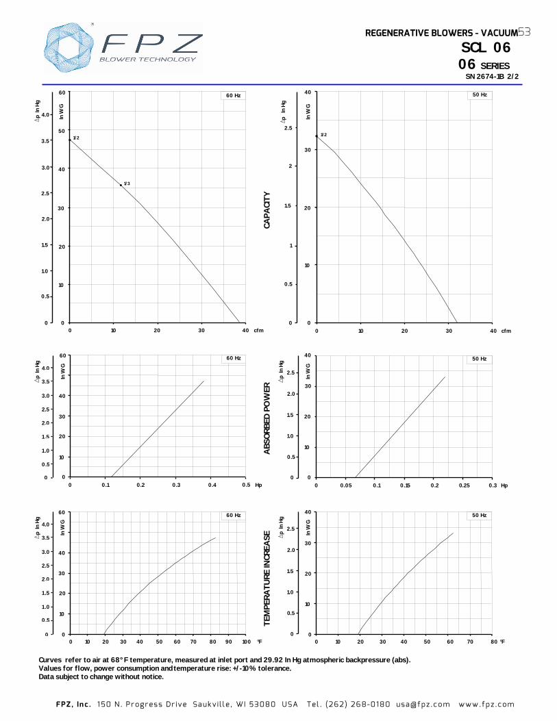
FPZ , In c . 1 50 N . Pr ogr es s Dr ive Sa uk v i l l e , WI 5308 0 USA Tel . (262 ) 26 8-01 80 usa@ fpz .c o m www.fp z .c om
Curves refer to air at 68° F temperature, measured at Values for flow, power consumption and Data subject to change without notice.
ABS
ORB
ED P
OW
ER
TEM
PERA
TURE
INCR
EASE
SCL 06
SN 2674-
CAPA
CITY
In W
G
0
10
20
40
Hp
50 Hz
0 0.05 0.1 0.15 0.2 0.30 25
30
0
1.0
2.0
0.5
1.5
2.5
p I
n Hg
40
0
10
20
In W
G
30
0 30 50 60 80 °F
50 Hz
2010 40 700
1.0
2.0
0 5
1.5
2.5
p I
n Hg
In W
G
60
0
10
20
30
40
0 0.1 Hp0.2 0.3 0.4 0.5
60 Hz
0
1 ,0
2,0
3,0
4,0
0,5
1 ,5
2,5
3,5 p I
n Hg
40
0 30 50 60 80 °F0
10
20
In W
G 60 Hz
20
30
10 40 70
60
90 1000
1 ,0
2,0
3,0
4,0
0,5
1 ,5
2,5
3,5 p I
n Hg
0
10
20
40
In W
G
30
0 10 20 30 40
50 Hz
1/2
cfm
p
In H
g
0
1
2
0.5
1.5
2.5
p I
n Hg
0
1.0
2.0
3.0
4 0
0.5
1.5
2.5
3.5
cfm0
10
20
30
40
50
60
In W
G
0 10 20 30 40
60 Hz
1/3
1/2
06 SERIES
.
.
.
53REGENERATIVE BLOWERS - VACUUM
temperature rise: +/-10% tolerance. inlet port and 29.92 In Hg atmospheric backpressure (abs).
1B 2/2

FPZ , In c . 1 50 N . Pr ogr es s Dr ive Sa uk v i l l e , WI 5308 0 USA Tel . (262 ) 26 8-01 80 usa@ fpz .c o m www.fp z .c om
SCL 10DL / 15DH
SN 2198-4B 1/2
- For proper use, the blower should be equipped with inlet filter and safety valve; other accessories available on request. - Ambient temperature from +5° to +104°F. - Specifications subject to change without notice.
Model Maximum
flow cfm
Installed power
Hp
Maximum differential pressure
∆p ( In Hg)
Noise level Lp dB (A)
(1)
Overall dimensions
H Weight
60 Hz 50 Hz 60 Hz 50 Hz 60 Hz 50 Hz 60 Hz 50 Hz 3500 rpm 2900 rpm 3500 rpm 2900 rpm 3500 rpm 2900 rpm 3500 rpm 2900 rpm
Inches Lbs
21 18 1/2 1/2 6.3 4.9 64.0 62.0 12.76 23.50 3/4 3/4 7.7 63.7 61.7 14.25 32.50 35 29 1 1 8.1 64.0 62.0 15.75 40.00
(1) Noise measured at 1 m distance with inlet and outlet ports piped, in accordance to ISO 3744.
Model a b c d e f G I m n o r s
8.66 10.08 9.06 0.91 8.27 7.09 1/2" NPT 2.28 0.35 4.72 5.67 3.54 0.10
9.84 11.26 0.10
STANDARD FEATURES - Low weight cast aluminum construction. - Quiet operation with integral inlet and outlet
muffling. - Recognized TEFC - cURus motor. - High efficiency / low noise impeller design. - No lubrication / maintenance required. - Allowed ambient: +5 °F to +104 °F. - Mountable in any plane.
OPTIONS - Remote drive models (belt or coupling). - Special voltages. - Surface treatment or plating. - Gas tight sealing. - Special designs available.
ACCESSORIES - Inlet and/or inline filters. - Additional inlet/outlet silencers. - Safety valves. - Flow converting devices. - Optionals connectors
d
G
rnoH
l
a
øm fe
b
c
s
Dimensions in inches. Dimension for reference only.
MD
54 REGENERATIVE BLOWERS - VACUUM
1.18 8.27 7.09 3/4" NPT 2.52 0.35 4.72 5.67 4.72
7.28.1
10DL-MD
10DL-MD
15DH-MD
15DH-MD
SERIES
0.16

FPZ , In c . 1 50 N . Pr ogr es s Dr ive Sa uk v i l l e , WI 5308 0 USA Tel . (262 ) 26 8-01 80 usa@ fpz .c o m www.fp z .c om
Curves refer to air at 68° F temperature, measured at inlet port and 29.92 In Hg atmospheric backpressure (abs). Values for flow, power consumption and temperature rise: +/-10% tolerance. Data subject to change without notice.
ABS
ORB
ED P
OW
ER
TEM
PERA
TURE
INCR
EASE
CA
PACI
TY
80
120
60
40
20
0 1 Hp 0,8 0,6 0,4 0,2 0
In W
G
50 Hz
10DL
15DH
p I
n Hg
0 1
2
3
4
5
6
7
8
0
1
2
3
4
5
6
7
8 p I
n Hg
0
1
2
3
4
5
6
7
8
0
1
2
3
4
5
6
7
8
p I
n Hg
°F
p I
n H
g
0 1
2
3
4
5
6
7
8
12060 80 10040 20 0
In W
G
60
80
120
40
20
0
50 Hz
10DL
15DH
p I
n H
g
0 1
2
3
4
5
6
7
8
120
In W
G
80
60
40
20
0 0 0,2 0,4 0,6 1 Hp0,8
10DL
15DH
60 Hz
p I
n Hg
0 1
2
3
4
5
6
7
8
cfm 40 30 20 10 0
40
20
0
80
120
In W
G
100
1
1/2
50 Hz
3/4
10DL
15DH
80
60
40
20
0°F
120
In W
G
100 12080 60 40 20 0
15DH
10DL
60 Hz
60 1/3
cfm 0
20
40
60
80
100
120
0 20 4010 30
In W
G 1
60 Hz
10DL
15DH
1/2
3/4
55REGENERATIVE BLOWERS - VACUUM
SCL 10DL / 15DH
SN 2198-4B /2 MD
2 SERIES
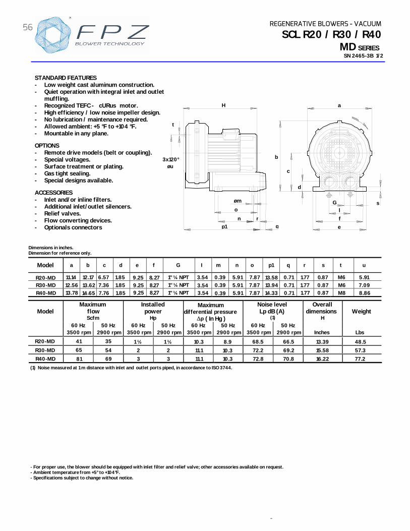
-
- For proper use, the blower should be equipped with inlet filter and relief valve; other accessories available on request. - Ambient temperature from +5° to +104°F. - Specifications subject to change without notice.
Model Maximum
flow Scfm
Installed power
Hp ∆p
Noise level Lp dB (A)
(1)
Overall dimensions
H Weight
60 Hz 50 Hz 60 Hz 50 Hz 60 Hz 50 Hz 60 Hz 50 Hz 3500 rpm 2900 rpm 3500 rpm 2900 rpm 3500 rpm 2900 rpm 3500 rpm 2900 rpm Inches Lbs
1 ½ 1 ½ 13. 48.5 2 2 69.2 15.58 57.3 3 3 10.3 72.8 16.22 77.2
(1) Noise measured at 1 m distance with inlet and outlet ports piped, in accordance to ISO 3744.
SCL R20 / R30 / R40
SN 2465-3B 1/2
STANDARD FEATURES - Low weight cast aluminum construction. - Quiet operation with integral inlet and outlet
muffling. - Recognized TEFC - cURus motor. - High efficiency / low noise impeller design. - No lubrication / maintenance required. - Allowed ambient: +5 °F to +104 °F. - Mountable in any plane.
OPTIONS - Remote drive models (belt or coupling). - Special voltages. - Surface treatment or plating. - Gas tight sealing. - Special designs available.
ACCESSORIES - Inlet and/or inline filters. - Additional inlet/outlet silencers. - - Flow converting devices. - Optionals connectors
Dimensions in inches. Dimension for reference only.
Model a b c d e f G I m n o p1 q t
11.14 12.17 6.57 1.85 1” ¼ NPT 12.56 7.36 0.71 0.87 M6 09 13.78 7.76 0 .71
sl
G
d
c
a
fe
b
r
øm
p1
o
nq
H
3x120° øu
t
MD
11
0. 87 5 91
REGENERATIVE BLOWERS - VACUUM
3.54 0.39 5.91 7.87 0.71 1.77 13.58 0R2 -MD
35 R20-MD 41
9 . 2 5 8. . 2 70.390.39
R30-MD R40-MD 14.65
13.62 1.85 1.85
9 . 2 5 8 . 2 79 . 2 5 8 . 2 7
1” ¼ NPT 1” ¼ NPT
3.54 3.54
5.91 5.91
7.877.87
3.944.33
r
1.77 1.77 0.87
s
M8
M6
u
. 7.
8.86
R30-MD R40-MD
54 65
69 8110.3 72.2
68.5 66.5
70.8
39
SERIES
Maximum differential pressure
( In Hg )
10.3 11.1
8.9
11.1
Relief valves.
56

FPZ , In c . 1 50 N . Pr ogr es s Dr ive Sa uk v i l l e , WI 5308 0 USA Tel . (262 ) 26 8-01 80 usa@ fpz .c o m www.fp z .c om
Curves refer to air at 68° F temperature, measured at Values for flow, power consumption and Data subject to change without notice.
ABS
ORB
ED P
OW
ER
TEM
PERA
TURE
INCR
EASE
SN 2465- 2/2
CAPA
CITY
p I
n Hg
0 1
2
3
4
5
6
7
8
9
10
11
100
160
120
80
60
40
20
0 100 140120 80 60 40 20 0
In W
G 60 Hz
°F
p I
n Hg
0
1
2
3
4
5
6
7
8
9
10
11
cfm
50 Hz
100 80 60 40 20 0
60
40
20
0
80
100
120
140
160
2
1 1/2
In W
G
3
p
In
Hg
0
1
2
3
4
5
6
7
8
9
10
11
2 5 Hp 2 1.5 1 0.5 0
60
80
100
120
160
40
20
0
In W
G 50 Hz
p I
n Hg
0 1
2
3
4
5
6
7
8
9
10
11
In W
G
160
120 100 80 60 40 20
0 0 0.5 1 1.5 2 2.5 3 3 5 Hp
60 Hz
p I
n Hg
0
1
2
3
4
5
6
7
8
9
10
11
cfm 100 80 0 20 40 60 1200
20
40
60
80
100
120
140
160
2
60 Hz
In W
G
3
..
temperature rise: +/-10% tolerance.
R20-MD
R20-MD R20-MD
1 1/2
R20-MD
R30-MD
R40-MD
SCL R20 / R30 / R40 MD
REGENERATIVE BLOWERS - VACUUM
SERIES3B
R20-MD
R30-MD
R40-MD
R30-MD
R40-MD
R30-MD
R40-MD
R40-MD
R30-MD
inlet port and 29.92 In Hg atmospheric backpressure (abs).
p I
n Hg
0 1
2
3
4
5
6
7
8
9
10
11
100
160
120
80
60
40
20
0 100 140120 80 60 40 20 0
In W
G
°F
R20-MD
R40-MD
50 Hz
R30-MD
57
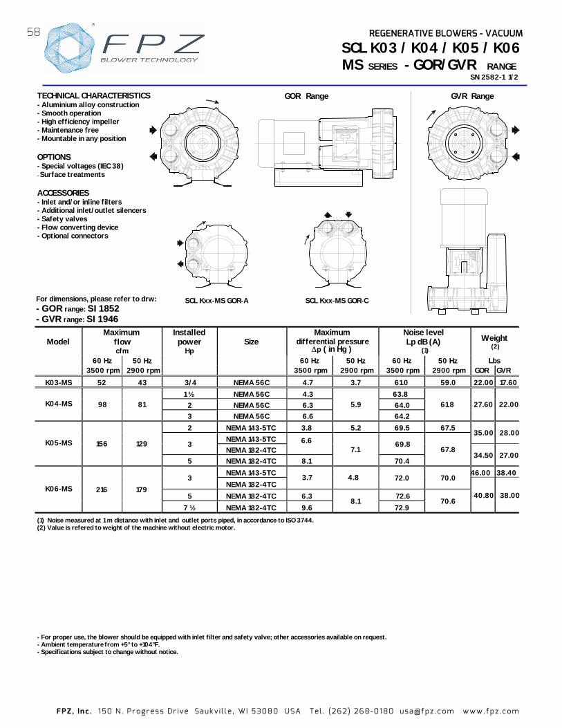
FPZ , In c . 1 50 N . Pr ogr es s Dr ive Sa uk v i l l e , WI 5308 0 USA Tel . (262 ) 26 8-01 80 usa@ fpz .c o m www.fp z .c om
TECHNICAL CHARACTERISTICS - Aluminium alloy construction - Smooth operation - High efficiency impeller - Maintenance free - Mountable in any position OPTIONS - Special voltages (IEC 38) - Surface treatments ACCESSORIES - Inlet and/or inline filters - Additional inlet/outlet silencers - Safety valves - Flow converting device - Optional connectors
Model Maximum
flow cfm
Installed power
Hp Size
Maximum differential pressure
Noise level Lp dB (A)
(1) Weight
(2) 60 Hz 50 Hz 60 Hz 50 Hz 60 Hz 50 Hz Lbs 3500 rpm 2900 rpm 3500 rpm 2900 rpm 3500 rpm 2900 rpm GOR GVR
K03-MS 52 43 3/4 NEMA 56C 4.7 3.7 61.0 59.0 22.00 17.601 ½ NEMA 56C 4.3 63.8
2 NEMA 56C 6.3 K04-MS 98 81
3 NEMA 56C 6.6
5.9
64.2
61.8 27.60 22.00
2 NEMA 143-5TC 3.8 5.2 69.5 67.5 NEMA 143-5TC
35.00 28.003
NEMA 182-4TC 69.8 K05-MS 156 129
5 NEMA 182-4TC 8.1 7.1
70.4 67.8
34.50 27.00
NEMA 143-5TC 46.00 38.403
NEMA 182-4TC 3.7 4.8 72.0 70.0
5 NEMA 182-4TC 6.3 K06-MS 216 179
7 ½ NEMA 182-4TC 9.6 8.1
72.9 70.6
40.80 38.00
(1) Noise measured at 1 m distance with inlet and outlet ports piped, in accordance to ISO 3744. (2) Value is refered to weight of the machine without electric motor.
SCL K03 / K04 / K05 / K06MS SERIES - GOR/GVR RANGE
SN 2582-1 1/2
- For proper use, the blower should be equipped with inlet filter - Ambient temperature rom +5° to +104°F. - Specifications subject to change without notice.
For dimensions, please refer to drw: -- GG OO RR range: SS II 11 885522 -- GG VVRR range: SS II 11 994466
GOR Range GVR Range
SCL Kxx-MS GOR-A SCL Kxx-MS GOR-C
58 REGENERATIVE BLOWERS - VACUUM
and safety valve; other accessories available on request.
∆p ( in Hg )
6.6
f
72.6
64.0

FPZ , In c . 1 50 N . Pr ogr es s Dr ive Sa uk v i l l e , WI 5308 0 USA Tel . (262 ) 26 8-01 80 usa@ fpz .c o m www.fp z .c om
CAPA
CITY
A
BSO
RBED
PO
WER
TE
MPE
RATU
RE IN
CREA
SE
SCL K03 / K04 / K05 / K06MS SERIES - GOR/GVR RANGE
SN 2582- 2/2
Curves refer to air at 68° F temperature, measured at inlet port and 29.92 In Hg atmospheric backpressure (abs). Values for flow, power consumption and Data subject to change without notice.
p
In H
g
0
1
2
3
4
5
6
7
8
9
10
2
3
5
0
20
40
60
80
100
120
140
0 50 100 150 200 250
In W
G 60 Hz
cfm
7 1/2
5
3
1 1/2
3
3/4
K05-MS K06-MS K04-MS K03-MS
2
p
In H
g
0
1
2
3
4
5
6
7
8
9
10
0 20 40 60 80 100 120 140 160 180 200 °F
0
20
40
60
80
100
140
In W
G 60 Hz
K06-MS
K04-MS
K03-MS
K05-MS
p
In H
g
0
1
2
3
4
5
6
7
8
2
3
0
20
40
60
80
100
120
0 50 100 150 200 cfm
In W
G 50 Hz
5
3
1 1/2
3/4
K05-MS K06-MSK04-MSK03-MS
p
In H
g
0
1
2
3
4
5
6
7
8
0
20
40
60
80
120
In W
G
0 1 2 3 4 5 Hp
50 Hz
K05-MS
K06-MS
K04-MS
K03-MS
p
In H
g
0
1
2
3
4
5
6
7
8
0
20
40
60
80
120
0 20 40 60 80 100 120 140 160 180 200 °F
50 Hz
In W
G
K04-MS
K03-MS
K06-MS
K05-MS
0
1
2
3
4
5
6
7
8
9
10
p
In H
g
0
20
40
60
80
100
140
0 1 2 3 4 5 6 7
In W
G
60 Hz
K05-MS
K06-MS
K04-MS
K03-MS
Hp
REGENERATIVE BLOWERS - VACUUM
temperature rise: +/-10% tolerance.
1
59

FPZ , In c . 1 50 N . Pr ogr es s Dr ive Sa uk v i l l e , WI 5308 0 USA Tel . (262 ) 26 8-01 80 usa@ fpz .c o m www.fp z .c om
Model Maximum
flow cfm
Installed power
Hp Size
Maximum differential pressure
Noise level Lp dB (A)
(1)
Weight (2)
60 Hz 50 Hz 60 Hz 50 Hz 60 Hz 50 Hz 3500 rpm 2900 rpm 3500 rpm 2900 rpm 3500 rpm 2900 rpm Lbs
5 NEMA 182-4TC 5.1 6.3 78.0 76.0 110.50
NEMA 182-4TC 110.50 K07-MS 294 243 7 ½
NEMA 213-5TC 9.6 8.8 78.3 76.3
110.50
5 NEMA 182-4TC 2.8 3.8 78.8 76.8 127.00
NEMA 182-4TC 127.00 7 ½
NEMA 213-5TC 5.0 6.6 79.1 77.1
127.00
10 NEMA 213-5TC 127.00
NEMA 213-5TC 127.00
K08-MS 381 316
15 NEMA 254-6TC
10.3 9.2
79.7 77.4
130.60
NEMA 182-4TC 133.40 7 ½
NEMA 213-5TC 3.7 4.6 79.3 77.3
133.40
10 NEMA 213-5TC 5.9 7.0 79.6 77.6 133.40
NEMA 213-5TC 133.40
K09-MS 471 390
15 NEMA 254-6TC
10.3 9.6 80.4
78.1 137.00
NEMA 182-4TC 147.30 7 ½
NEMA 213-5TC 2.2 3.7 79.4 77.4
147.30
10 NEMA 213-5TC 4.4 5.9 79.7 77.7 147.30
NEMA 213-5TC 147.30 15
NEMA 254-6TC 8.1 80.2
151.00
K10-MS 556 460
20 NEMA 254-6TC 10.3 9.6
80.5 78.2
151.00
10 NEMA 213-5TC 2.9 3.9 82.0 80.0 170.00
NEMA 213-5TC 170.00 15
NEMA 254-6TC 5.9 7.1 82.5 80.5
176.40
20 NEMA 254-6TC 9.2 83.0 176.40
K11-MS 650 539
25 NEMA 284-6TSC 10.3 9.6
83.8 81.0
170.00
NEMA 213-5TC 177.70 15
NEMA 254-6TC 3.8 6.6 83.5 81.5
184.10
20 NEMA 254-6TSC 6.3 84.3 184.10
25 NEMA 284-6TSC 8.8 87.2 177.70
K12-MS 726 602
30 NEMA 284-6TSC 10.3 9.6
87.6 82.3
177.70
SCL K07 / K08 / K09 / K10 / K11 / K12MS SERIES - GOR/GVR RANGE
SN 21 35-3 1 /2
- For proper use, the blower should be equipped with inlet filte nd safety valve; other accessories available on request. - Ambient temperature rom +5° to +104°F. - Specifications subject to change without notice.
(1) Noise measured at 1 m distance with inlet and outlet ports piped, in accordance to ISO 3744. (2) Value is refered to weight of the machine without electric motor
GVR RangeGOR Range
SCL Kxx-MS GOR-C
SCL Kxx-MS GOR-A SCL Kxx-MS GOR-B
For dimensions, please refer to drw: GG OO RR range: SS II 11 887733 GG VVRR range: SS II 11 992200
TECHNICAL CHARACTERISTICS - Aluminium alloy construction - Smooth operation - High efficiency impeller - Maintenance free - Mountable in any position
OPTIONS - Special voltages (IEC 38) - Surface treatments
ACCESSORIES - Inlet and/or inline filters - Additional inlet/outlet silencers - Safety valves - Flow converting device - Optional connectors
60 REGENERATIVE BLOWERS - VACUUM
r a
80.1
79.4
∆p ( in Hg )
f
8.5

FPZ , In c . 1 50 N . Pr ogr es s Dr ive Sa uk v i l l e , WI 5308 0 USA Tel . (262 ) 26 8-01 80 usa@ fpz .c o m www.fp z .c om
Curves refer to air at 68° F temperature, measured inlet port and 29.92 In Hg atmospheric backpressure (abs). Values for flow, power consumption and Data subject to change without notice.
CAPA
CITY
A
BSO
RBED
PO
WER
TE
MPE
RATU
RE IN
CREA
SE
SCL K07 / K08 / K09 / K10 / K11 / K12MS SERIES - GOR/GVR RANGE
SN 2135- 2/2
0 1 2
3
4
5
6
7
8
9
10
11
p I
n Hg
K11-MS
K09-MS
K08-MS K07-MS
K10-MS
60 Hz
Hp 0 5 10 15 20 250
20 40 60 80
100 120
160
In W
G
K12-MS
0 1 2
3
4
5
6
7
8
9
10
11
p I
n Hg
0 20 40 60 80 100 120 140 160 °F
0 20
40
60
80
100
120
160
In W
G
180
60 Hz
K10-MS K08-MS
K11-MS
K09-MS
K07-MS
K12-MS
0
1
2
3
4
5
6
7
8
9
10
p I
n Hg
50 Hz
K07-MS K11-MS
K10-MS
K09-MS
0
20
40
60
80
100
140
In W
G
Hp0 8 182 4 6 10 12 14 16
K08-MS K12-MS
0
1
2
3
4
5
6
7
8
9
10
p I
n Hg
50 Hz
0 20 40 60 100 120 140 160 °F
0
20
40
60
80
100
In W
G
80
K08-MS
K09-MS
K11-MS
K07-MS
K10-MS
K12-MS
140
0
1
2
3
4
5
6
7
8
9
10
11
p I
n Hg
200 300 400 500 8000 100 600 700 0
20
40
60
80
100
120
140
In W
G
160
K11-MS
K08-MS
7 1/2
10
15
10
15 20 25
15
20
15
10
5
7 1/2
10
7 1/2
K07-MS K09-MS
K10-MS
5
7 1/2
30
25
15
K12-MS
60 Hz
20
0
1
2
3
4
5
6
7
8
9
10
p I
n Hg
0 100 200 300 400 500 700 cfm 0
20
40
60
80
100
120
140
In W
G
600
K07-MS
K10-MS K08-MS
K11-MSK09-MS
K12-MS
10
15
5
7 1/2
10
7 1/2
7 1/2 10
15
2015
10
5
7 1/2
20
15
50 Hz
61REGENERATIVE BLOWERS - VACUUM
temperature rise: +/-10% tolerance.
3
cfm
at

FPZ , In c . 1 50 N . Pr ogr es s Dr ive Sa uk v i l l e , WI 5308 0 USA Tel . (262 ) 26 8-01 80 usa@ fpz .c o m www.fp z .c om
- For proper use, the blower should be equipped with inlet filter - Ambient temperature rom +5° to +104°F. - Specifications subject to change without notice.
(1) Noise measured at 1 m distance with inlet and outlet ports piped, in accordance to ISO 3744. (2) Value is refered to weight of the machine without electric motor.
SCL K05 / K06TS SERIES - GOR / GVR USA RANGE
SN 2688-1 1/2
For dimensions, please refer to drw: -- GG OO RR range: SS II 2211 2233 -- GG VVRR range: SS II 2211 3355
Model Maximum
flow m³/h
Installed power
Hp Size
Maximum differential pressure
∆p ( in Hg )
Noise level Lp dB (A)
(1)
Weight (2)
60 Hz 50 Hz 60 Hz 50 Hz 60 Hz 50 Hz Lbs 3500 rpm 2900 rpm 3500 rpm 2900 rpm GOR GVR
5.0 4.4 6.3 75.1 73.1 K05-TS 290 241 7.5
NEMA 182-4TC7.4 6.7 77.1 75.1
72.75 68.35
7.5 4.1 5.7 77.1 75.1 10 5.9 77.4 75.4 K06-TS 400 331
15
NEMA 213-5TC
7.8 7.4
78.0 76.0
112.45 108.00
TECHNICAL CHARACTERISTICS - Aluminium alloy construction - Smooth operation - High efficiency impeller - Maintenance free - Mountable in any plane - G1/8'' female thread on both suction and discharge silencer port flanges. OPTIONS - Special voltages (IEC 38) - Surface treatments
SCL Kxx-TS GOR-C
G 1/8”
GVR RangeGOR Range
G 1/8”
SCL Kxx-TS GOR-A SCL Kxx-TS GOR-B SCL Kxx-TS GOR-C
62 REGENERATIVE BLOWERS - VACUUM
and safety valve; other accessories available on request. f
3500 rpm 2900 rpm

FPZ , In c . 1 50 N . Pr ogr es s Dr ive Sa uk v i l l e , WI 5308 0 USA Tel . (262 ) 26 8-01 80 usa@ fpz .c o m www.fp z .c om
SCL K05 / K06TS SERIES - GOR/GVR RANGE
SN 2688- 2/2
CAPA
CITY
A
BSO
RBED
PO
WER
TE
MPE
RATU
RE IN
CREA
SE
60 Hz
In W
G
0
20
40
60
80
120
0 100 200 300 400 500 Scfm
7 1/2
5
10
60 Hz
0
20
40
60
80
120
0 1 2 3 4 5 6 7 8 Hp
In W
G
9 12
K05-TS
K06-TS
K05-TS
K06-TS
0 20 40 60 80 °F 0
20
40
60
120
In W
G
60 Hz
0 1 2 3 4 5 6 7 8 Hp9 100
20
40
60
80
120
In W
G
K05-TS
K06-TS
50 Hz
K06-TS
50 Hz
0 20 40 80 140 °F 60 100 120
K05-TS
0
20
40
60
80
120
In W
G
20
40
60
80
100
120
0 50 100 150 200 250 300 350 4000
Scfm
In W
G
K05-TS
K06-TS
5
7 1/2
7 1/2
10100
15
7 1/2
10 11
80
100 120 140
50 Hz
K05-TS
K06-TS
p
In
Hg
0
1
2
3
4
5
6
7
8
p
In
Hg
0
1
2
3
4
5
6
7
8
p
In
Hg
0
1
2
3
4
5
6
7
8
p
In
Hg
0
1
2
3
4
5
6
7
8
p
In
Hg
0
1
2
3
4
5
6
7
8
p
In
Hg
0
1
2
3
4
5
6
7
8
Curves refer to air at 20°C temperature, measured at inlet port and 1013 mbar (abs) atmospheric backpressure. Values for flow, power consumption and Data subject to change without notice.
63REGENERATIVE BLOWERS - VACUUM
temperature rise: +/-10% tolerance.
1

FPZ , In c . 1 50 N . Pr ogr es s Dr ive Sa uk v i l l e , WI 5308 0 USA Tel . (262 ) 26 8-01 80 usa@ fpz .c o m www.fp z .c om
SCL K07 / K08 / K09 / K10 / K11 / K12 TS SERIES - GOR/GVR RANGE
SN 2165-4 1/2
For dimensions, please refer to drw: GG OO RR range: SS II 11 887799 GG VVRR range: SS II 11 888800
- For proper use, the blower should be equipped with inlet filter and safety valve; other accessories a vailable on request.
- Ambient temperature from +5° to +104° F. - Specifications subject to change without notice.
(1) Noise measured at 1 m distance with inlet and outlet ports piped, in accordance to ISO 3744. (2) Value is refered to weight of the machine without electric motor (3) Not applicable on SCL Kxx - GVR
SCL Kxx-TS GOR-A
SCL Kxx-TS GOR-B
GVR RANGE
TECHNICAL CHARACTERISTICS - Aluminium alloy construction - Smooth operation - High efficiency impeller - Maintenance free - Mountable in any position - G1/8” female thread on both
suction and discharge silencer port flanges
OPTIONS - Special voltages (IEC 38) - Surface treatments
ACCESSORIES - Inlet and/or inline filters - Additional inlet/outlet silencers - Safety valves - Flow converting device - Optional connectors
SCL Kxx-TS GOR-C
GOR RANGE
G 1/8”
G 1/8”
Model Maximum
flow cfm
Installed
power
Hp
Size Maximum
differential pressure ∆∆∆∆p ( In Hg )
Noise level Lp dB (A)
(1)
Weight (2)
60 Hz 50 Hz 60 Hz 50 Hz 60 Hz 50 Hz 3500 rpm 2900 rpm 3500 rpm 2900 rpm 3500 rpm 2
NEMA 182-4TC 2.6 4.4 84.5 82.5 160.90 7 ½
NEMA 213-5TC 2.6 4.4 84.5 82.5 160.90
10 NEMA 213-5TC 4.4 6.6 84.8 82.8 160.90
NEMA 213-5TC 8.1 8.1 85.4 83.4 160.90 15
NEMA 254-6TC (3) 167.60
K07-TS 588 487
20 NEMA 254-6TC (3) 8.8 8.1 85.9 83.4 167.60
10 NEMA 213-5TC 2.7 4.7 81.2 79.2 172.00
NEMA 213-5TC 5. 5 7.7 82.9 80.9 172.00 15
NEMA 254-6TC (3) 5.5 7.7 82.9 80.9 180.80 20 NEMA 254-6TC (3) 7.4 8.8 84.8 80.8 180.80
K08-TS 715 592
25 NEMA 284-6TSC (3) 9.6 8.8 87.0 80.8 174.20
NEMA 213-5TC 3.8 5.5 82.2 80.2 202.80 15
NEMA 254-6TC (3) 3.8 5.5 82.2 80.2 208.30
20 NEMA 254-6TC (3) 5.9 7.9 84.1 82.1 208.30 25 NEMA 284-6TSC (3) 8.1 8.8 86.1 84.1 205.00
30 NEMA 284-6TSC (3) 8.8 8.8 88.1 84.1 205.00
K09-TS 941 780
40 NEMA 324-6TSC (3) 9.6 8.8 90.1 84.1 220.50
NEMA 213-5TC 3.0 4.7 89.1 87.1 209.40 15
NEMA 254-6TC (3) 3.0 4.7 89.1 87.1 216.10 20 NEMA 254-6TC (3) 4.8 6.6 89.4 87.4 216.10
25 NEMA 284-6TSC (3) 5.9 8.1 89.7 87.7 211.60
30 NEMA 284-6TSC (3) 7.4 9.6 90.0 88.0 211.60
K10-TS 1093 906
40 NEMA 324-6TSC (3) 10.3 9.6 90.3 88.0 227.10
25 NEMA 284-6TSC 3.7 6.5 90.7 88.7 251.30
30 NEMA 284-6TSC 5.1 8.1 91.3 89.3 251.30
40 NEMA 324-6TSC (3) 7.4 9.6 91.9 89.9 269.00 K11-TS 1254 1039
50 NEMA 324-6TSC (3) 10.3 9.6 92.5 89.9 269.00
30 NEMA 284-6TSC 3.3 5.9 91.9 89.9 249.10
40 NEMA 324-6TSC (3) 5.2 8.8 92.5 90.5 266.80 K12-TS 1410 1168
50 NEMA 324-6TSC (3) 8.1 - 93.1 - 266.80
64 REGENERATIVE BLOWERS - VACUUM
900 rpm Lbs
8.1 8.1 85.4 83.4
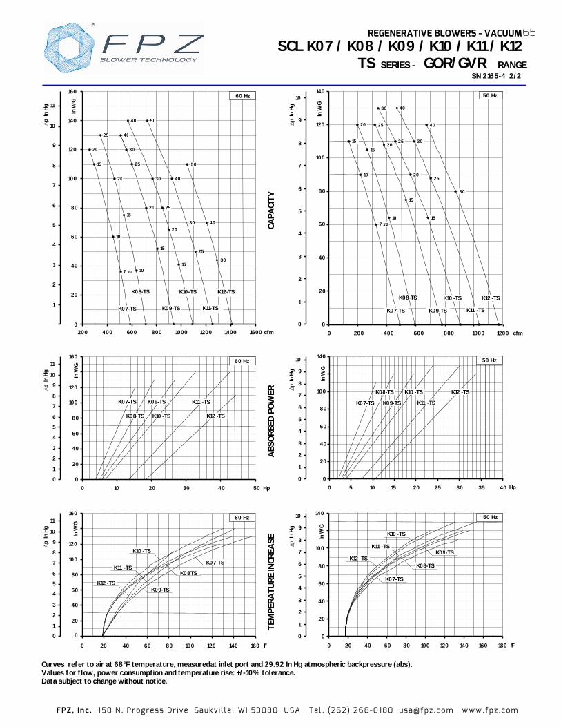
FPZ , In c . 1 50 N . Pr ogr es s Dr ive Sa uk v i l l e , WI 5308 0 USA Tel . (262 ) 26 8-01 80 usa@ fpz .c o m www.fp z .c om
Curves refer to air at 68° F temperature, measured at inlet port and 29.92 In Hg atmospheric backpressure (abs). Values for flow, power consumption and temperature rise: +/-10% tolerance. Data subject to change without notice.
CAPA
CITY
A
BSO
RBED
PO
WER
TE
MPE
RATU
RE IN
CREA
SE
SCL K07 / K08 / K09 / K10 / K11 / K12 TS SERIES - GOR/GVR RANGE
SN 2165- 2/2
0
1
2
3
4
5
6
7
8
9
10
11
p I
n Hg
K10 -TS
K09-TS
K08TS K11 -TS
K07-TS
0 20 40 60 80 100 120 140 160 °F
0
20
40
60
80
100
120
160
In W
G 60 Hz
K12 -TS
0
1
2
3
4
5
6
7
8
9
10
p I
n Hg
0 20 40 60 80 100 120 140 160 °F 180
0
20
40
60
80
100
140
In W
G
K08-TS
K10 -TS
K09-TS K11 -TS
K12 -TS
K07-TS
50 Hz
0
1
2
3
4
5
6
7
8
9
10
p I
n Hg
0
20
40
60
80
100
140
In W
G
0 10 5 15 20 25 30
K07-TS K11 -TS
K10 -TS K08-TS
K09-TS
35 Hp 40
K12 -TS
50 Hz
0
1
2
3
4
5
6
7
8
9
10
p I
n Hg
0
20
40
60
80
100
120
140
In W
G
0 200 400 600 800 1000 1200 cfm
K07-TS
K10 -TS K08-TS
K11 -TS K09-TS
15
15
25
30
40 30
25
20
7 1/2
10
15
20
15
10
20
25
K12 -TS
40
30
50 Hz
K11 -TS K09-TS
K08-TS
K07-TS
K10 -TS
Hp 0 10 20 30 40 50
0
20
40
60
80
100
120
160
In W
G
0
1
2
3
4
5
6
7
8
9
10
11
p I
n Hg
K12 -TS
60 Hz
1
2
3
4
5
6
7
8
9
10
11
p I
n Hg
0
20
40
60
80
100
120
140
In W
G
160
200 400 600 800 1000 1200 1400
10
7 1/2
15 20
25
20
15
10
15
20
25 30
40 40 50
30 40
25
20
15 25
30
K07-TS
K08-TS K10-TS
K11-TS K09-TS
50
40
30
1600 cfm
K12-TS
60 Hz
65REGENERATIVE BLOWERS - VACUUM
4
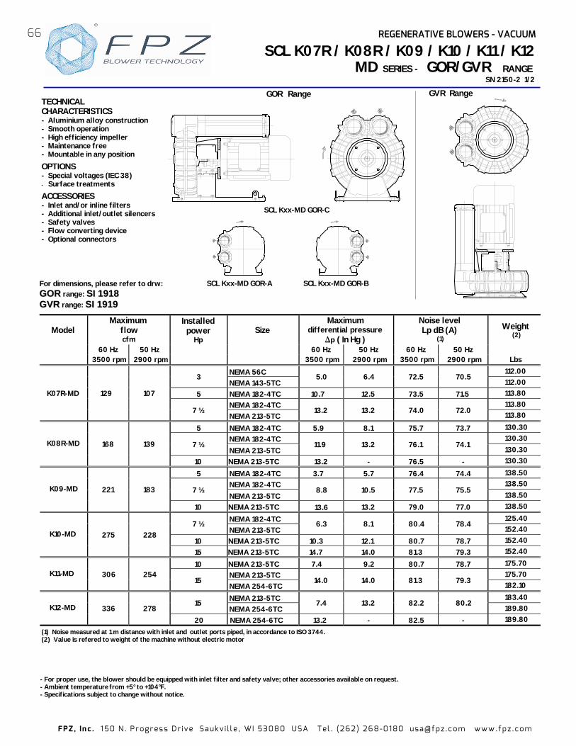
FPZ , In c . 1 50 N . Pr ogr es s Dr ive Sa uk v i l l e , WI 5308 0 USA Tel . (262 ) 26 8-01 80 usa@ fpz .c o m www.fp z .c om
Model Maximum
flow cfm
Installed power
Hp Size
Maximum differential pressure
∆p ( In Hg )
Noise level Lp dB (A)
(1)
Weight (2)
60 Hz 50 Hz 60 Hz 50 Hz 60 Hz 50 Hz 3500 rpm 2900 rpm 3500 rpm 2900 rpm 3500 rpm 2900 rpm Lbs
NEMA 56C 112.00 3
NEMA 143-5TC 5.0 6.4 72.5 70.5
112.00 5 NEMA 182-4TC 10.7 12.5 73.5 71.5 113.80
NEMA 182-4TC 113.80 K07R-MD 129 107
7 ½ NEMA 213-5TC
13.2 13.2 74.0 72.0 113.80
5 NEMA 182-4TC 5.9 8.1 75.7 73.7 130.30 NEMA 182-4TC 130.30
7 ½ NEMA 213-5TC
11.9 13.2 76.1 74.1 130.30
K08R-MD 168 139
10 NEMA 213-5TC - 76.5 - 130.30
5 NEMA 182-4TC 3.7 5.7 76.4 74.4 138.50 NEMA 182-4TC 138.50
7 ½ NEMA 213-5TC
8.8 10.5 77.5 75.5 138.50
K09-MD 221 183
10 NEMA 213-5TC 13.2 79.0 77.0 138.50
NEMA 182-4TC 125.40 7 ½
NEMA 213-5TC 6.3 8.1 80.4 78.4
152.40 10 NEMA 213-5TC 10.3 12.1 80.7 78.7 152.40
K10-MD 275 228
15 NEMA 213-5TC 14.7 14.0 81.3 79.3 152.40
10 NEMA 213-5TC 7.4 9.2 80.7 78.7 175.70 NEMA 213-5TC 175.70 K11-MD 306 254
15 NEMA 254-6TC
14.0 14.0 81.3 79.3 182.10
NEMA 213-5TC 183.40 15
NEMA 254-6TC 7.4 13.2 82.2 80.2
189.80 K12-MD 336 278 20 NEMA 254-6TC 13.2 - 82.5 - 189.80
SCL K07R / K08R / K09 / K10 / K11 / K12MD SERIES - GOR/GVR RANGE
SN 2150-2 1/2
TECHNICAL CHARACTERISTICS - Aluminium alloy construction - Smooth operation - High efficiency impeller - Maintenance free - Mountable in any position
OPTIONS - Special voltages (IEC 38) - Surface treatments
ACCESSORIES - Inlet and/or inline filters - Additional inlet/outlet silencers - Safety valves - Flow converting device - Optional connectors
For dimensions, please refer to drw: GG OO RR range: SS II 11 9911 88 GG VVRR range: SS II 11 9911 99
- For proper use, the blower should be equipped with inlet filter - Ambient temperature rom +5° to +104°F. - Specifications subject to change without notice.
(1) Noise measured at 1 m distance with inlet and outlet ports piped, in accordance to ISO 3744. (2) Value is refered to weight of the machine without electric motor
GVR Range GOR Range
SCL Kxx-MD GOR-C
SCL Kxx-MD GOR-A
SCL Kxx-MD GOR-B
66 REGENERATIVE BLOWERS - VACUUM
and safety valve; other accessories available on request.
13.2
f
13.6

FPZ , In c . 1 50 N . Pr ogr es s Dr ive Sa uk v i l l e , WI 5308 0 USA Tel . (262 ) 26 8-01 80 usa@ fpz .c o m www.fp z .c om
Curves refer to air at 68° F temperature, measured at Values for flow, power consumption and Data subject to change without notice.
CAPA
CITY
A
BSO
RBED
PO
WER
TE
MPE
RATU
RE IN
CREA
SE
SCL K07R / K08R / K09 / K10 / K11 / K12MD SERIES - GOR/GVR RANGE
SN 2150- 2/2
Hp 0 2 10 12 18 200
20 40 60 80
100 120 140
In W
G
4 6 8
160
220
∆p
In H
g
0 1 2 3 4 5 6 7 8 9
10 11 12 13 14 15 16
14 16
60 Hz
K07R-MD
K11-MD K10-MD
K08R-MD
K09-MD K12-MD
K08R-MD
K09-MD
K07R-MD
K10-MD
K11-MD 50 Hz
0 20 40 60 100 120 140 160 °F 80 180
0
20
40
60
80
100
120
In W
G
140
200
∆p
In H
g
0 1 2 3 4 5 6 7 8 9
10 11 12 13 14
K12-MD
0 20 40 60 80
100 120
In W
G
140
200
Hp0 8 2 4 6 10 12
∆p
In H
g
0 12 3 4 567 8 9
1011 12 13 14
14
K07R-MD
K11-MD K10-MD
K08R-MD
K09-MD K12-MD
50 Hz
∆p
In H
g
0
1
2
3
4
5
6
7
8
9
10
11
12
13
14
0 100 200 300 cfm 0
20
40
60
80
100
120
140
In W
G
160
200
K07R-MD
K10-MD K08R-MD
K11-MD K09-MD
3
7 1/2
10
7 1/2
15
5 7 1/2
10
5
5
7 1/2 10
15
K12-MD
15
50 Hz
°F
0 20
40
60
80
100
120
220
In W
G
140
160
0 20 40 60 80 100 120 140 160 180 200
K10-MD
K08R-MD K07R-MD
K11-MD
K09-MD
∆p
In H
g
0 1 2 3 4 5 6 7 8 9
10 11 12 13 14 15 16
K12-MD
60 Hz
cfm
∆p
In H
g
0 1
2
3
4
5
6
7
8
9
10
11
12
13
14
15
16
0
20
40
60
80
100
120
140
In W
G
160
180
220
200 300 4000 100
K10-MD
K11-MDK09-MD
60 Hz
15 7 1/2
15 10
5
3 5
5
7 1/2
10
10
7 1/2
7 1/2
K12-MD
15
20
K07R-MD
K08R-MD
10
67REGENERATIVE BLOWERS - VACUUM
temperature rise: +/-10% tolerance. inlet port and 29.92 In Hg atmospheric backpressure (abs).
2

FPZ , In c . 1 50 N . Pr ogr es s Dr ive Sa uk v i l l e , WI 5308 0 USA Tel . (262 ) 26 8-01 80 usa@ fpz .c o m www.fp z .c om
- For proper use, the blower should be equipped with inlet filter and safety valve; other accessories a vailable on request. - Ambient temperature from +5° to +104° F. - Specifications subject to change without notice.
Model Maximum
flow cfm
Installed power
Hp Size
Maximum differential pressure
∆∆∆∆p ( In Hg )
Noise level Lp dB (A)
(1)
Weight (2)
60 Hz 50 Hz 60 Hz 50 Hz 60 Hz 50 Hz 3500 rpm 2900 rpm 3500 rpm 2900 rpm 3500 rpm 2900 rpm Lbs
K07-TD 296 245
7 ½ NEMA 182-4TC
6.6 9.6 78.6 76.6 156.50 NEMA 213-5TC
10 NEMA 213-5TC
12.5
78.9
76.9
156.50
15 NEMA 213-5TC
13.2 79.5 156.50
NEMA 254-6TC 160.90
K08-TD 368 305 10 NEMA 213-5TC 7.0 10.3 79.3 77.3 169.80
15 NEMA 213-5TC
12.5 12.5 79.9 77.9 169.80
NEMA 254-6TC 178.60
K09-TD 467 387 15
NEMA 213-5TC 7.7 11.4 82.2 80.2
196.20 NEMA 254-6TC 201.70
20 NEMA 254-6TC 11.7 12.5
82.5 80.5
201.70 25 NEMA 284-6TSC 13.2 198.40
K10-TD 571 473 15
NEMA 213-5TC 6.3 9.6 85.9 83.9
202.80
NEMA 254-6TC 209.50
20 NEMA 254-6TC 9.6 13.2
86.2 84.2
209.50 25 NEMA 284-6TSC 13.2 205.00
K11-TD 642 532
20 NEMA 254-6TC 6.6 10.3 86.7 84.7 246.80 25 NEMA 284-6TSC 9.6
13.2
87.2
85.2
244.70
30 NEMA 284-6TSC 11.0
40 NEMA 324-6TSC 12.5 88.1 264.50
K12-TD 716 593 25 NEMA 284-6TSC 6.3 10.3 87.5 85.5 242.5 30 NEMA 284-6TSC 8.8 13.2 88.0 86.0 242.5 40 NEMA 324-6TSC 12.5 - 88.4 - 262.3
(1) Noise measured at 1 m distance with inlet and outlet ports piped, in accordance to ISO 3744. (2) Value is refered to weight of the machine without electric motor
For dimensions, please refer to drw:
SCL K07 / K08 / K09 / K10 / K11 / K12TD SERIES - GOR RANGE
SN 2180-4 1/2
TECHNICAL CHARACTERISTICS - Aluminium alloy construction - Smooth operation - High efficiency impeller - Maintenance free - Mountable in any position - G1/8” female thread on both
suction and discharge silencer port flanges
OPTIONS - Special voltages (IEC 38) - Surface treatments
ACCESSORIES - Inlet and/or inline filters - Additional inlet/outlet silencers - Safety valves - Flow converting device - Optional connectors
G 1/8”
68 REGENERATIVE BLOWERS - VACUUM
87.7 244.70
86.5
82.8
SI1971
9.9

FPZ , In c . 1 50 N . Pr ogr es s Dr ive Sa uk v i l l e , WI 5308 0 USA Tel . (262 ) 26 8-01 80 usa@ fpz .c o m www.fp z .c om
Curves refer to air at 68° F temperature, measured at inlet port and 29.92 In Hg atmospheric backpressure (abs). Values for flow, power consumption and temperature rise: +/-10% tolerance. Data subject to change without notice.
CAPA
CITY
A
BSO
RBED
PO
WER
TE
MPE
RATU
RE IN
CREA
SE
SCL K07 / K08 / K09 / K10 / K11 / K12TD SERIES - GOR RANGE
SN 2180- 2/2
200
0 1
2 3 4 5 6 7 8
9 10 11 12 13 14
p I
n Hg
0 1
2 3 4 5 6 7 8 9
10 11 12 13 14
p I
n H
g
0 20 40 60 80 100 120 140 160 °F 180
0
20
40
60
80
100
120
140
200
160
In W
G
K07-TD
K09-TD
K11 -TD
K08-TD
K10 -TD
0
1
2
3
4
5
6
7
8
9
10
11
12
13
14
p I
n H
g
100 200 300 500 400 600 700 0
20
40
60
80
100
120
140
In W
G
160
200
K07-TD
K08-TD
K09-TD
10
25 15
20
15
25
10 15
20
K10-TD
K11-TD
20
40
30
25
7 1/2
15
0 cfm 800
K12-TD
25
30
40
60 Hz
0
20
40
60
80
100
120
140
160
In W
G
K11 -TD
K08-TD
K09-TD
K10 -TD
K07-TD
Hp 0 10 20 30 5 15 25 35
K12 -TD
60 Hz
K12 -TD
60 Hz
cfm 0
1
2
3
4
5
6
7
8
9
10
11
12
13
14
p I
n H
g
0 1
2 3 4 5 6 7 8
9 10 11 12 13 14
p I
n Hg
0 20 40 60 80 100 120 140 160 180 °F 0
20
40
60
80
100
120
140
160
200
In W
G
K07-TD
K09-TD
K11 -TD
K08-TD
K10 -TD
0 1
2 3 4 5 6
7 8 9
10 11 12 13 14
p I
n Hg
0
20
40
60
80
100
120
140
160
In W
G
200
K07-TD
K10 -TD K08-TD
K11-TD K09-TD
20
25 20
15 10
10
15
15
20
0 100 200 300 400 500 600 700
K12 -TD
30
25
7 1/2
50 Hz
Hp 0 5 20 25
0
20
40
60
80
100
120
In W
G
140
160
200
10 15
K11 -TD
K08-TD
K09-TD
K10 -TD
K07-TD
30
50 Hz
K12 -TD
K12 -TD
50 Hz
REGENERATIVE BLOWERS - VACUUM
4
69

FPZ , In c . 1 50 N . Pr ogr es s Dr ive Sa uk v i l l e , WI 5308 0 USA Tel . (262 ) 26 8-01 80 usa@ fpz .c o m www.fp z .c om
5
7
1
11
6
2
810
9
48
10
9
7
6
3
1
11
From a wide range of accessories, thecustomer can select the most suitable for
machine.
1 - Cartridge filter2 - Inline filter3 - Filter manifold4 - Relief valve5 - Vacuum valve6 - Check valve7 - Control valve8 - Pressure / Vacuum gauge9 - Sleeve10 - Flexible hose11 - Additional silencer
ACCESSORIES
Installation Guide
their application. In all cases, FPZ suggests toinstall an inlet filter and safety valve on every
Pressure
Vacuum
70

FPZ , In c . 1 50 N . Pr ogr es s Dr ive Sa uk v i l l e , WI 5308 0 USA Tel . (262 ) 26 8-01 80 usa@ fpz .c o m www.fp z .c om
ACCESSORIES
BA
C
eGauges, Check Valves, Silencers, Enclosures
Dimensions in inches - unbinding and can be changed without prior notice.
Part # Used on models A B CIH1 SCL K03-MS 13.4 18.2 15.8IH3 SCL K04-MS 14.3 19.7 16.5IH5 SCL K05-6 MS + 30-40DH 16.9 26.8 21.3IH7 SCL K07-8 MS / MD 31.7 64.4 26IH8 SCL K07-8 TD 31.7 64.4 26IH9 SCL K07-8 TS 31.7 64.4 26
IH10 SC L K09-1 MS/MD 31.7 67.2 30IH11 SCL K09-10 TD 31.7 67.2 30IH12 SCL K11-TD 31.7 67.2 30IH13 SCL K09-11 TS 31.7 67.2 31.5
ØD ØC
A BE
F
TYPE D A B C E F SS 4 SS 5 SS 6 SS 8 SS 9
Steel manufactured (apart from SI 9 / SS 9 - entirely in aluminium) wthe noise is reduced
7.5 5.5 2.8 2 0.6lbs 0.8 1” 1/4
7.9 6.7 3.1 1.2 0.8
0.8
0.8 0.8
1.1 1.3
9.9 4.8
1” 1/2 9.1 7.9 3.5 2” 19.1 15.7 6.0 3.3 3” 18.3 16.9 6.7 1.1
1.2
4”
B
1/4 NPT
øA
Gauges are important for monitoring the operating pressure or vacuum of the blower. Gauges should be positioned as close to the blower as possible.
Gauges
Dimensions in inches. Tolerance on given values ± 1 0% - unbinding and can be changed without prior notice.
Dimensions in inches. Tolerance on given values ± 1 0% - unbinding and can be changed without prior notice.
Check Valves backflow into the blower and are supplied in bronze or brass.
Silencers
Sound Enclosures
Silencers provide additional sound attenuation.
sound absorbing polyurethane element.
Swing check valves allow air to flow in one direction. These valves prevent
A
B
C
Dimensions in inches. Tolerance on given values ± 1 0% - unbinding and can be changed without prior notice.
2
ith
Part number
Duty Scale A B
VG25-60 Vacuum 2
VG25-200 Vacuum 2
VG25-300 Vacuum 2O 2.88 2.59PG25-60 Pressure 2O
PG25-200 Pressure 2OPG25-300 Pressure 2OPG25-15 Pressure 1 s 2.7
SS1708
Part Number
NPT A B C
CV075 0.75" 2.4CV10 1" 2.8 2.7 1.9
CV125 1.25" 3.2 3.2 2.2CV15 1.5" 3.6 3.5 2.5CV20 2" 4.3CV30 3" 5.8 6.1 4.2CV40 4" 6.9 7.1
*
*PG25-15 is suitable f o r o utd o o r use
2.25
0-60" H O0-200"H O 0-300" H0-60" H
0-200" H0-300" H
0- 5 p i
4.2 3.1
5.5
71

FPZ , In c . 1 50 N . Pr ogr es s Dr ive Sa uk v i l l e , WI 5308 0 USA Tel . (262 ) 26 8-01 80 usa@ fpz .c o m www.fp z .c om
ACCESSORIES
Safety Valves SS1
®
72
Model HPSafety Valve
VacuumSafety Valve
PressureModel HP
Safety Valve Vacuum
Safety Valve Pressure
K03-MS 3/4 VRL6 VRL6 K09-TS 20 VRL9 VRL9K04-MS ALL VRL6 VRL6 K09-TS 25 VRL8 VRL9K05-MS ALL VRL6 VRL6 K10-TS 20 (2) VRL9 (2) VRL9K06-MS 3 VRL6 VRL8 K10-TS 25 VRL9 VRL9K06-MS 4 VRL6 VRL6 K11-TS 25 (2) VRL9 (2) VRL9K06-MS 5 1/2 VRL6 VRL6 K11-TS 30 (2) VRL9 (2) VRL9K06-MS 6 1/5 VRL6 VRL6 K12-TS 30 (3) VRL9 (3) VRL9K07-MS 4 VRL8 VRL8K07-MS 5 1/2 VRL6 VRL8K07-MS 7 1/2 VRL6 VRL6K07-MS 10 VRL6 VRL6 15DH ALL VRL6 VRL6K08-MS 5.5 VRL8 VRL9 R20-MD ALL VRL6 VRL6K08-MS 7 1/2 VRL8 VRL8 R30-MD ALL VRL6 VRL6K08-MS 10 VRL6 VRL8 R40-MD ALL VRL6 VRL6K08-MS 15 VRL6 VRL6 K07-MD 5 1/2 VRL6 VRL6K09-MS 7 1/2 VRL9 VRL9 K07-MD 7.5 VRL6 VRL6-HPK09-MS 10 VRL8 VRL8 K07R-MD 10 VRL6-HP VRL6-HPK09-MS 15 VRL6 VRL8 K08-MD 5 1/2 VRL6 VRL6K09-MS 20 VRL6 VRL6 K08-MD 7 1/2 VRL6 VRL6K10-MS 7 1/2 VRL9 VRL9 K08-MD 10 VRL6 VRL6K10-MS 10 VRL9 VRL9 K08-MD 15 - VRL6-HPK10-MS 15 VRL8 VRL8 K09-MD 10 VRL6 VRL6K10-MS 20 VRL8 VRL8 K09-MD 15 - VRL6-HPK10-MS 25 - VRL6 K10-MD 10 VRL6 VRL6K11-MS 10 VRL9 VRL9 K10-MD 15 VRL6 VRL6K11-MS 15 VRL9 VRL9 K10-MD 20 - VRL6-HPK11-MS 20 VRL8 VRL8 K11-MD 15 VRL6 VRL8K12-MS 15 VRL9 VRL9 K11-MD 20 VRL6 VRL6-HPK12-MS 20 VRL9 VRL9 K12-MD 15 VRL8 VRL8K12-MS 25 VRL8 VRL8 K12-MD 20 VRL6 VRL8K05-TS 5.5 VRL8 VRL8 K12-MD 25 -K06-TS 5 1/2 VRL9 VRL9 K05-TD 5 1/2 VRL6 VRL6K06-TS 7 1/2 VRL8 VRL8 K06-TD 10 VRL6 VRL6K06-TS 10 VRL6 VRL8 K07-TD 15 VRL6 VRL6K07-TS 7 1/2 VRL9 VRL9 K08-TD 15 VRL6 VRL6K07-TS 10 VRL9 VRL9 K09-TD 25 VRL6 VRL6K07-TS 15 VRL8 VRL8 K10-TD 25 VRL6 VRL8K08-TS 15 VRL9 VRL9 K11-TD 25 VRL8 VRL8
K12-TD 30 VRL8 VRL8
Valve selections are based on 60 Hz operation and refer to air having a density equal to 0.075 lbs / cu. Ft and inlet temperature of 68 deg F. Data is subject to change without notice
Single Stage Blowers
The following table is a guide to select the appropriate safety valve. The selections in the table are based on blowers operating at 60 Hz - for 50 hz applications refer to the safety valve data sheets. To select the appropriate safety valve, determine the blower model, horsepower, and whether it is to be used for vacuum or pressure service. If it is desirable to have the valve activate at lower pressures than the maximum rated pressure or vacuum of the blower, a different safety valve might be required (refer to safety valve data sheets). In some cases, two valves are required. FPZ valves are supplied uncalibrated. All safety valves included detailed instructions on how to calibrate and install the valve.
Single Stage Blowers
Two Stage Blowers
Model HPSafety Valve
VacuumSafety Valve
Pressure
VRL6
702

FPZ , In c . 1 50 N . Pr ogr es s Dr ive Sa uk v i l l e , WI 5308 0 USA Tel . (262 ) 26 8-01 80 usa@ fpz .c o m www.fp z .c om
Capacity
Pres
sure
/ V
acuu
m
180
Scfm
150
120
90
60
In WG
30
0
Psig
210
240
0 200 400 600 800 1000 1200 1400 1600 1800 2000 2200
In H g
0
2
4
6
8
10
12
14
16
18
0
1
2
3
4
5
6
7
8
TYPE ND D A B H WEIGHT (Lbs)
2” 2” NPT 4.02 6.90 0.47 1 .9
3” 3” NPT 5.31 7.48 0.59 4.2
VRL9 4” 4” NPT 6.30 8.11 0.71 5.7
ØD
ØA
B
ØD
H
H
OPERATING RANGE
OVERALL DIMENSIONS
• Dimensions in inches.
• Specifications subject to change without prior notice.
VRL6 VRL8 VRL9
The VRL valves are designed to protect blowers and / or motors from over pressurization or excess vacuum. When there is over pressurization, the valve opens and discharges to the outside. When there is excess in vacuum, the valve opens and takes flow from outside. The valves have been designed for low pressure / low vacuum, with minimal difference between the initial value at which the valve begins to open and its fully opened position. The valves are supplied with 2 different springs to maximize their efficiency. These compact valves, made of aluminum al loy, are both easy to install and calibrate, and operate in a wide range of capacities.
a secondary external outlet when working in pressure conditions,or to pipe ary flow when working in vacuum. a
"HP" valves are used for pressures >240" H2O.
The VRL can be plumbed to divert excess primary flow through
in second
Maximum efficiency is achieved by keeping operating values (flow versus pressure or vacuum) within the operating range (shaded area on graph). Capacity refers to air having a densityequal to 0.075 lbs./cu.ft .
VRL6 VRL8 VRL9
SN 1733 -6 1/1
ACCESSORIES
Safety Valves
®
VRL6 HP VRL8 HP
VR6 & VRL6 HP
VRL8 & VRL8HP
VRL6 HP VRL8 HP270
300
9
10 20
VRL valves are supplied uncalibrated - contact FPZ for calibration options.
73

74
Inline Filters SS1506
ACCESSORIES
®
Various media available Epoxy coated housings Special connections Available in Stainless Steel Activated carbon prefilter to reduce
odor Alternate Top-to-canister fastening
system for low pressure or pulsating systems
Polyester: 99%+ removal efficiency standard to 5 micron Stainless steel torsion clips for durability Rugged all steel construction with Baked enamel finish Low pressure drop Positive sealing O-ring seal system Large dirt holding capacity and easy field cleaning, especially when mounted horizontally or inverted Fully-drawn one piece canister Filter change out differential: 10”-15” H2O Over Initial Delta P
FPZ inline filters are typically used in vacuum applications to prevent debris from entering the blower. Inline filters consist of a metal housing with a metal cover retained by quick - change clamps for easy servicing of the element. Polyester elements are recommended for humid applications.
CT Series
Service area needed
Dimension tolerance + 1/8”
CSL Series Service area needed
Inlet (process)
Service area needed
B
G C
F
Connect to blower
A D
B
A
G
E
* Male x male npt connections Dimensions for reference only
DIMENSIONS
(Inches)
Polyester Element
NPT A B C D E F G Used on Models Approx Wt. Lbs
CSL-843-050HC ½” 4 3/8 9/16 5 7/8 2 ½ 9/16 5 3 ¼ 10DL 3
CSL-843-075HC ¾” 4 3/8 9/16 5 7/8 2 ½ 9/16 5 3 ¼ 15DH 3
CSL-843-100HC 1” 4 3/8 ¾ 5 7/8 2 ½ ¾ 5 3 ¼ 06 3
CSL-843-125HC 1 ¼” 4 3/8 ¾ 5 7/8 2 ½ ¾ 5 3 ¼ K03-MS, R20-MD, R30-MD, R40-MD 3
CSL-849-150HC 1 ½” 6 ½ ¾ 7 5/16 4 ½ ¾ 6 13/16 5 ¼ K04-MS, 30DH, 40DH 5
CSL-851-200HC 2” 10 ¼ ¾ 8 ¾ 5 ¾ 7 5/8 9 ¼K05-MS, K06-MS, K05-TD, K06-TD, K07R-
MD, K08R-MD 15
CT-235P-300C 3" 18 13/16 9 7/8 13 1/2 16 4/5 13 1/8 10 14 K05-TS, K06-TS, K07-MS, K08-MS,
K07-TD, K08-TD 30
CT-235P-400C 4" 18 13/16 9 7/8 13 1/2 16 4/5 13 1/8 10 14 K09-MS, K10-MS, K09-MD, K10-MD, K11-
MD, K12-MD, K09-TD, K10-TD 29
CSL-335P-400* 4" 27 1/8 3 14 18 1/2 3 12 15 K07-TS, K08-TS, K11-MS, K12-MS,
K11-TD, K12-TD 30
CT-275P-500C 5” 18 ¼ 16 19 14 3/8 9 7/8 14 ¾ 20 K09-TS, K10-TS 50
CTD-375P-500C 5” 25 3/8 16 19 21 1/2 17 14 ¾ 35 K11-TS, K12-TS 60
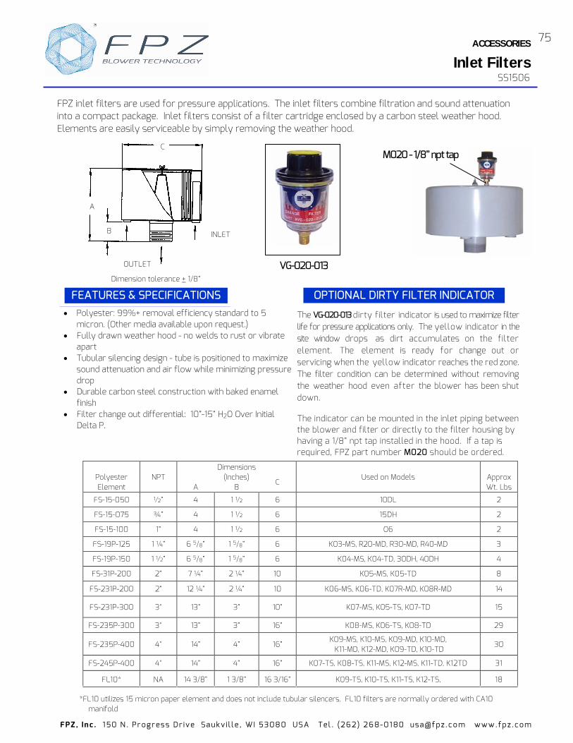
ACCESSORIES
Inlet Filters
75
FPZ , In c . 1 50 N . Pr ogr es s Dr ive Sa uk v i l l e , WI 5308 0 USA Tel . (262 ) 26 8-01 80 usa@ fpz .c o m www.fp z .c om
SS1506
Polyester Element
NPT
A
Dimensions (Inches)
B
C
Used on Models
Approx Wt. Lbs
FS-15-050 ½” 4 1 ½ 6 10DL 2
FS-15-075 ¾” 4 1 ½ 6 15DH 2
FS-15-100 1” 4 1 ½ 6 O6 2
FS-19P-125 1 ¼” 6 5/8” 1 5/8” 6 K03-MS, R20-MD, R30-MD, R40-MD 3
FS-19P-150 1 ½” 6 5/8” 1 5/8” 6 K04-MS, K04-TD, 30DH, 40DH 4
FS-31P-200 2” 7 ¼” 2 ¼” 10 K05-MS, K05-TD 8
FS-231P-200 2” 12 ¼” 2 ¼” 10 K06-MS, K06-TD, K07R-MD, K08R-MD 14
FS-231P-300 3" 13” 3” 10” K07-MS, K05-TS, K07-TD 15
FS-235P-300 3" 13” 3” 16” K08-MS, K06-TS, K08-TD 29
FS-235P-400 4" 14” 4” 16” K09-MS, K10-MS, K09-MD, K10-MD, K11-MD, K12-MD, K09-TD, K10-TD
30
FS-245P-400 4" 14” 4” 16” K07-TS, K08-TS, K11-MS, K12-MS, K11-TD, K12TD 31
FL10* NA 14 3/8” 1 3/8” 16 3/16” K09-TS, K10-TS, K11-TS, K12-TS, 18
Polyester: 99%+ removal efficiency standard to 5 micron. (Other media available upon request.)
Fully drawn weather hood - no welds to rust or vibrate apart
Tubular silencing design - tube is positioned to maximize sound attenuation and air flow while minimizing pressure drop
Durable carbon steel construction with baked enamel finish
Filter change out differential: 10”-15” H2O Over Initial Delta P.
FEATURES & SPECIFICATIONS
FPZ inlet filters are used for pressure applications. The inlet filters combine filtration and sound attenuation into a compact package. Inlet filters consist of a filter cartridge enclosed by a carbon steel weather hood. Elements are easily serviceable by simply removing the weather hood.
Dimension tolerance + 1/8”
INLET
OUTLET
FEATURES & SPECIFICATIONS OPTIONAL DIRTY FILTER INDICATOR
C
A
B
The VG-020-013 dirty filter indicator is used to maximize filter life for pressure applications only. The yellow indicator in the site window drops as dirt accumulates on the filter element. The element is ready for change out or servicing when the yellow indicator reaches the red zone. The filter condition can be determined without removing the weather hood even after the blower has been shut down. The indicator can be mounted in the inlet piping between the blower and filter or directly to the filter housing by having a 1/8” npt tap installed in the hood. If a tap is required, FPZ part number M020 should be ordered.
*FL10 utilizes 15 micron paper element and does not include tubular silencers. FL10 filters are normally ordered with CA10 manifold
M020 - 1/8” npt tap
VG-020-013

FPZ , In c . 1 50 N . Pr ogr es s Dr ive Sa uk v i l l e , WI 5308 0 USA Tel . (262 ) 26 8-01 80 usa@ fpz .c o m www.fp z .c om
SN 2048-2
VK - FLANGE CONNECTOR FOR VRL VALVES This VK flange accessory allows direct connection of the VRL relief valves to the cover of the SCL "K" model blowers;
Fig. 1
R
G
S1
H
I
S
Fig. 2
S1
G
I
R
S H
VK flange
VRL
SCL K
SCL K
CK accessory
VK flange
VRL
Fig. 2
ØD
I
R
S H
S1
Fig. 1
R
ØD
I
S
S1
H
PK - FLANGED TUBE CONNECTOR FOR SCL K The PK accessory allows connection of the "K" Series blowers direct CHARACTERISTICS Flange in aluminium alloy with tube stub connection.
SCL K
MF accessory PK accessory
Supplied as a kit for mounting (with gasket and screws with ve Parts List in table.
ACCESSORIESVK / PK Flange Connectors
Model DN G H I R S S1 Fig. Parts List VK 5 1” 1/2 1” ½ NPT 1.18 3.62 0.26 0.59 0.39 SP 1552 VK 6 2” 2” NPT 1.97 4.33 0.33 0.75 0.39
1 SP 1553
VK 6A 2“ 2” NPT 2.34 5.12 0.35 0.75 0.43 SP 1611 VK 8 3” 3” NPT 1.69 5.12 0.35 0.83 0.43 SP 1554 VK 9 4” 4” NPT 1.81 5.90 0.35 0.90 0.43
2 SP 1555
Dimensions in Inches
Model DN D H I R S S1 Fig. Parts List PK 5 1” 1/2 1.89 1.18 3.62 0.26 0.79 0.39 SP 1543 PK 6 2” 2.36 1.97 4.33 0.33 1.38 0.39
1 SP 1544
PK 6A 2” 2.36 2.34 5.12 0.35 1.38 0.43 SP 1609 PK 8 3” 3.46 1.69 5.12 0.35 0.94 0.43 SP 1545 PK 9 4” 4.48 1.81 5.90 0.35 1.06 0.43
2 SP 1546
Dimensions in InchesFig. 2Fig. 1
either in pressure or vacuum. Note: VK flanges usable on K-MS and K-TS blowers in vacuum or pressure. K-MD useable in vacuum only.
Note: PK flanges usable on K-MS, K-TS, K-TD blowers in vacuum or pressure. K-MD useable in vacuum only.
76
ly to the process line without use of the intake or outlet manifolds.
wrench), please see the respecti
®

FPZ , In c . 1 50 N . Pr ogr es s Dr ive Sa uk v i l l e , WI 5308 0 USA Tel . (262 ) 26 8-01 80 usa@ fpz .c o m www.fp z .c om
This all aluminum device is simple in both design and operation. Change of flow direction is attain an electronically or pneumatically activated diverter.
C B A max
I
I
F
F
O
M
H
L
DN
0 20 40 60 80 100 120
0 0,5 1,0 1,5 mbar psig
VS 6
VS
m3/hcfm
“O” execution
TYPE DN A B C F H I L M O VS 6 2” 15.43 (1) 16.42 (2) 4.13 4.29 M6 4.33 2 x int.3.35 3.94 6.38 3.46 VS 8 3” 19.09 (1) 20.08 (2) 4.02 5.28 M6 6.3 4 x int.4.72 5.91 8.27 4.33
Overall dimensions refer to “O” execution without flanges
For the dimensions of the other executions pls see: SS II 11 778877 Executions O/P SS II 11 778888 Executions Y/H/K with pneumatic
control SS II 22002211 Executions Y/H/K with electrical
control
(2) Electronically activated(3) Pneumatically activated
50
100
200
300
400
500
600
800
1000
1400
0
50
100
200
300
400
500
600
800
VS 8
Pressure drop per side (inlet/outlet)
Dimensions in inches. Tolerance on given values ±10 % - unbinding and can be changed without prior not .
Available connection - TF threaded flange GAS (G 1 ½”, G 2”, G3”); - TF threaded flange NPT (NPT 1 ½”, NPT 2” , NPT 3”); - See SU 0012.
Other execution P - Y - H - K
With piped outlet
With double control
With collector and double control With double collector and double control
P Y
H K
EXECUTION
O / P Y / H / K
Electrical control
Thrust solenoid Working ratio 60% of cycle time Max. cycle duration 5 min. Max. activated time Power rating 56 W 120 W (3) Standard supply voltages V: 24 DC–110 AC–220 AC
Pneumatic control Thrust air cylindrer Double effect Max pressure 10 Bar Air consumption 0.02 litres/cycle Operating temperature -5°C ~ +70 °C
(3) Only for VS6 (dp max. +350/-350 mbar)
SN 2616- 1/1
ACCESSORIES
Flow Converting Devices771
V6 / VS8
ice
ed by
5 min.
3
®

FPZ , In c . 1 50 N . Pr ogr es s Dr ive Sa uk v i l l e , WI 5308 0 USA Tel . (262 ) 26 8-01 80 usa@ fpz .c o m www.fp z .c om
CA MANIFOLD FOR FA/FL FILTERS 90° wide radius PVC manifold with flanged connection and unthreaded tube end. Working temperature -20° to +40°C ( -5° ÷ + 1 05 °F).
ØD
B
A
S
R=2D
Fig. 2 I R
Fig. 3
R
I
Fig. 1 I
γ
R
ACCESSORIES
CA / CK Manifolds
I4
I2
C
I1
I3
B
I2
I1
G
I1 I2
I4 I3 B
I1 I2
C
øF
E1
øDA
øD
A
E
A
E
B
øD
E
øD
G
22.5
Int.I
9022.5
90°
C
ø
øF
22.5° Int.I
90°
22.5°
90°
G
C
Dimensions in inches - unbinding and can be changed without prior notice.
Fig. 1
Fig. 2
CK MANIFOLD
90° aluminium manifold for “K” models suppli
Dimensions in inches - unbinding and can be changed without prior notice.
Type DN A B D S I R Y Fig.CA4 1.25" 8.66 3.54 1.65 0.59 2.95 0.28 30O 1
CA4V 1.25" 8.66 3.54 1.65 0.59 2.52 0.28 - 2
CA5 1.5" 10.24 4.33 1.89 0.59 3.35 0.28 45O 1
CA5V 1.5" 10.24 4.33 1.89 0.59 2.95 0.28 - 2
CA6 2" 12.60 5.31 2.36 0.59 3.35 0.28 45O 1
CA6V 2" 12.60 5.31 2.36 0.59 3.35 0.28 - 2
CA8 3" 14.96 7.28 3.46 0.59 4.72 0.28 -
CA9 4" 15.75 9.25 4.45 0.79 5.91 0.35 - 3
CA10 5" 17.72 11.81 5.51 0.79 8.27 0.71 -
Type DN A B C D E E1 F G I I1 I2 I3 I4 Fig.CK4 1.25" 2.72 3.33 2.20 1.15 0.27 0.45 0.27 M6 - 0.57 0.57 2.76 2.76
CK5 1.5" 3.15 3.94 2.20 1.69 0.27 0.45 0.27 M6 - 0.69 0.69 3.35 3.35 1
CK6 2" 3.62 4.65 2.72 2.16 0.31 0.51 0.35 M8 - 0.73 0.95 3.92 4.10
CK8 3" 5.71 5.71 4.31 2.95 0.39 - 0.35 M8 5.12 - - - -
CK9 4" 6.50 6.50 5.22 3.54 0.39 - 0.35 M8 5.90 - - - - 2
CK10 5" 8.66 8.66 7.56 5.04 0.39 - 0.35 M8 7.48 - - - -
ed in a kit containing the gasket and bolts.
SS1401
SS1401
78

FPZ , In c . 1 50 N . Pr ogr es s Dr ive Sa uk v i l l e , WI 5308 0 USA Tel . (262 ) 26 8-01 80 usa@ fpz .c o m www.fp z .c om
TIPOTYPE DN D L
MF 1 1/2” 20 200MF 2 3/4“ 26 200MF 3 1” 32 200MF 4 1” 1/4 45 200MF 5 1” 1/2 50 250MF 6 2” 64 250MF 8 3” 89 330MF 9 4” 114
MF 10 5” 140 330
TIPOTYPE D H I 1 I 2 R 1 R 2 S
TF 3 1” npt 18 55 - 6.5 - 10TF 4 1” 1/4 npt 18 75 - 6.5 - 10
TF 4V 1” 1/4 npt 18 64 - 6.5 - 10TF 5 1” 1/2 npt 18 85 - 6.5 - 10
TF 5V 1” 1/2 npt 18 75 - 6.5 - 10TF 6 2” npt 18 85 - 6.5 - 10TF 8 3” npt 25 - 120 - 6.5 13TF 9 4” npt 25 - 150 - 9 13
Dimensions in mm. Tolerance on given values ± 10% - unbinding and can be change
FLEXIBLE SLEEVESteel reinforced rubber - coated fibreglass flex tubing, including 2adjustable hose clamps. Working temperature: -55 ÷ +176 °C (-67 ÷+350 °F). Maximum working pressure: 3 bar (44 psi).
THREADED FLANGEThreaded flange in aluminum alloy.
Fig. 1Mat.: Al
Fig. 3Mat.: Fe
Fig. 2Mat.: Al
TIPOTYPE DN D G H I R S Fig. TIPO
TYPE DN D G H I R S S1 Fig.
MP 1 1/2” 21 G 1/2” 100 - - 85 MP 5V 1” 1/2 48 - 35 75 6.5 25 -MP 2 3/4” 27 G 3/4” 100 - - 85 MP 6 2” 60 - 35 85 6.5 25 -MP 3 1” 33 - 35 55 6.5 25 MP 8 3” 88 - 45 120 6.5 32 - 2MP 4 1” 1/4 42 - 35 75 6.5 25 MP 9 4” 114 4” npt 100 - - 80 - 3
MP 4V 1” 1/4 42 - 35 64 6.5 25 MP 10 5” 140 5” npt 60 210 18 40 8 4MP 5 1” 1/2 48 - 35 85 6.5 25
3
SLEEVEAluminum alloy or steel flanged sleeve coupling.
1
1
Fig. 4Mat.: Fe
L
ØD
R1
SH
R2
I2
D
I1
R
ØD
SH
I IR
ØD
S H
ØD
G
SH
S1ØD
G
IR
S H
ACCESSORIESFlexible Sleeves / Flanges
SS1604
d without prior notice.
330
79

Engineering Information
TECHNICAL
FPZ , In c . 1 50 N . Pr ogr es s Dr ive Sa uk v i l l e , WI 5308 0 USA Tel . (262 ) 26 8-01 80 usa@ fpz .c o m www.fp z .c om
80
Altitude Versus Barometric Pressure
Length
Feet x 12 = Inches
Inches x 2.54 = cm
Feet x 0.3048 = meters
Flow
m3/h x 0.588 = cfm lpm x 0.03528 = cfm
cfm x 1.699 = m3/h cfm x 28.32 = lpm
Pressure
In. H 2O x 0.03613 = psi In. H 2O x 0.07355 = In. Hg
x = In. H 2O psi x 2.036 = In. Hg
Altitude
Pressure
Altitude
Pressure
Altitude
Pressure
Feet In Hg. Psia Feet In. Hg. Psia Feet In. Hg. Psia 0 29.92 14.70 1500 28.33 13.90 7000 23.09 11.34
500 29.38 14.43 2000 27.82 13.67 7500 22.65 11.12 600 29.28 14.38 2500 27.31 13.41 8000 22.22 10.90 700 29.18 14.33 3000 26.81 13.19 8500 21.80 10.70 800 29.07 14.28 3500 26.32 12.92 9000 21.38 10.50 900 28.97 14.23 4000 25.84 12.70 9500 20.98 10.90
1000 28.86 14.18 4500 25.36 12.45 10000 20.58 10.10 1100 28.75 14.09 5000 24.89 12.231200 28.65 14.04 5500 24.43 12.00 1300 28.54 13.99 6000 23.98 11.77 1400 28.44 13.94 6500 23.53 11.56
PSI In. H2O In. Hg mBar mmH2O 1 27.68 2.04 68.95 703.0
1.5 41.5 3.05 103.43 1054.5 2 55.4 4.07 137.90 1406.0
2.5 69.2 5.09 172.38 1757.5 3 83.0 6.11 206.85 2109.0
3.5 96.9 7.13 241.33 2460.5 4 110.7 8.14 275.80 2812.0
4.5 124.6 9.16 310.28 3163.5 5 138.4 10.18 344.75 3515.0
5.5 152.2 11.20 379.23 3866.5 6 166.1 12.22 413.70 4218.0
6.5 179.9 13.23 448.18 4569.5 7 193.8 14.25 482.65 4921.0
7.5 207.6 15.27 517.13 5272.5 8 221.4 16.29 551.60 5624.0
8.5 235.3 17.31 586.08 5975.5 9 249.1 18.32 620.55 6327.0
9.5 263.0 19.34 655.03 6678.5 10 276.8 20.36 689.50 7030.0
Barometric pressure varies in direct proportion to altitude. Example #1 – If a blower is required to deliver 2 psig at 5000 feet, what pressure at standard air is required?
Pressure = 29.92 / 24.89 x 2 = 2.4 psig Example #2 – If a blower is required to deliver 2 psig at standard air, what pressure will it deliver at 5000 feet?
Pressure = 24.89 / 29.92 x 2 = 1.66 psig
mbar 0.4019
20.1810500110001150012000
19.7919.4119.03
9.91 9.72 9.53 9.35
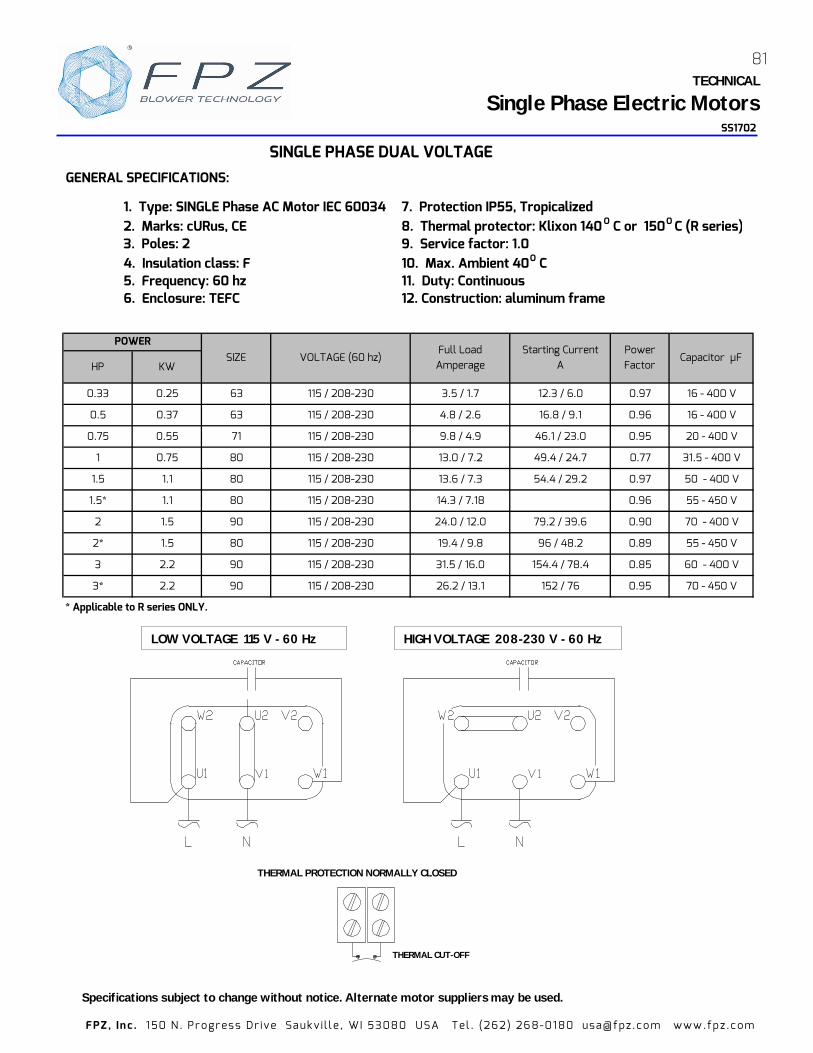
SS1702
GENERAL SPECIFICATIONS:
1. Type: SINGLE Phase AC Motor IEC 60034 7. Protection IP55, Tropicalized2. Marks: cURus, CE 8. Thermal protector: Klixon 140 O C or 150O C (R series)3. Poles: 2 9. Service factor: 1.04. Insulation class: F 10. Max. Ambient 40O C5. Frequency: 60 hz 11. Duty: Continuous6. Enclosure: TEFC 12. Construction: aluminum frame
HP KW
0.33 0.25 63 115 / 208-230 3.5 / 1.7 12.3 / 6.0 0.97 16 - 400 V
0.5 0.37 63 115 / 208-230 4.8 / 2.6 16.8 / 9.1 0.96 16 - 400 V
0.75 0.55 71 115 / 208-230 9.8 / 4.9 46.1 / 23.0 0.95 20 - 400 V
1 0.75 80 115 / 208-230 13.0 / 7.2 49.4 / 24.7 0.77 31.5 - 400 V
1.5 1.1 80 115 / 208-230 13.6 / 7.3 54.4 / 29.2 0.97 50 - 400 V
1.5* 1.1 80 115 / 208-230 14.3 / 7.18 0.96 55 - 450 V
2 1.5 90 115 / 208-230 24.0 / 12.0 79.2 / 39.6 0.90 70 - 400 V
2* 1.5 80 115 / 208-230 19.4 / 9.8 96 / 48.2 0.89 55 - 450 V
3 2.2 90 115 / 208-230 31.5 / 16.0 154.4 / 78.4 0.85 60 - 400 V
3* 2.2 90 115 / 208-230 26.2 / 13.1 152 / 76 0.95 70 - 450 V
* Applicable to R series ONLY.
VOLTAGE (60 hz)Full Load Amperage
Power Factor
Capacitor µFSIZEStarting Current
A
SINGLE PHASE DUAL VOLTAGE
POWER
THERMAL PROTECTION NORMALLY CLOSED
THERMAL CUT-OFF
LOW VOLTAGE 115 V - 60 Hz HIGH VOLTAGE 208-230 V - 60 Hz
TECHNICAL
81
Single Phase Electric Motors
FPZ , In c . 1 50 N . Pr ogr es s Dr ive Sa uk v i l l e , WI 5308 0 USA Tel . (262 ) 26 8-01 80 usa@ fpz .c o m www.fp z .c om
Specifications subject to change without notice. Alternate motor suppliers may be used.

GENERAL SPECIFICATIONS:1. Type: 3-phase AC Motor IEC 60034 7. Protection IP55, Tropicalized2. Marks: cURus, CE 8. Thermal protector: Klixon 150 O C3. Nema Premium Efficiency (IE3) - 1 HP AND LARGER (3 ph.) 9. Service factor: 1.15 (60 hz)4. Poles: 2 10. Max. Ambient 40O C5. Insulation class: F (B) 11. Duty: Continuous6. Enclosure: TEFC 12. Construction: aluminum frame
TECHNICAL
Three Phase Electric MotorSS17
THREE PHASE MOTOR
WIRING DIAGRAMS
∆ U2 V2 W2
U5 V5 W5
U1 V1 W1
U2 V2 W2
U5 V5 W5
U1 V1 W1
0.33 HP - 0.75 HP 1 HP - 15 HP (IE3) 20 - 30 HP (IE3)
HP KW SIZE VOLTAGEFLA
208-230 / 460 VEfficiency VOLTAGE
FLA 200/400 V
Efficiency
60 hz Starting Current Ratio*
0.33 0.25 63 208-230/460 1.5 / 0.7 59% 230/400 1.4 / 0.8 60.0% 3.9 M16 M200.5 0.37 63 208-230/460 2.3 / 1.0 59.2% 230/400 2.1 / 1.2 61.4% 3.6 M16 M20
0.75 0.55 71 208-230/460 2.7 / 1.2 68.8% 230/400 2.6 / 1.5 69.0% 3.8 M16 M20
1 0.75 80 208-230/460 2.99-2.94 / 1.47 77.0% 200/400 3.28 / 1.64 80.7% 8.0 M25 M25
1.5 1.1 80 208-230/460 4.35-4.34 / 2.17 84.0% 200/400 4.92 / 2.46 82.8% 9.3 M25 M25
80** 208-230/460 5.91-5.96 / 2.98 85.5% 200/400 6.82 / 3.41 84.2% 8.7 M25 M25
90 208-230/460 5.77-5.74 / 2.87 85.5% 200/400 6.58 / 3.29 84.2% 9.4 M25 M25
3 2.2 90 208-230/460 8.27-8.31 / 4.15 86.5% 200/400 9.6 / 4.8 85.9% 10.7 M25 M25
4 3 100 208-230/460 10.9-11.1 / 5.53 88.5% 200/400 12.86 / 6.38 87.1% 11.0 M25 M25
5.5 4 100 208-230/460 14.6-15.1 / 7.55 88.5% 200/400 17.7 / 8.86 88.1% 11.1 M25 M25
6.2 4.6 100 208-230/460 16.5-16.4 / 8.2 89.5% 200/400 19 / 9.5 88.6% 12.5 M25 M25
7.5 5.5 132 208-230/460 19.8-19.5 / 9.75 89.5% 200/400 22.2 / 11.1 89.2% 13.7 M25 M25
10 7.5 132 208-230/460 26.1-25 / 12.5 90.2% 200/400 28.6 / 14.3 90.1% 13.0 M25 M25
15 11 132 208-230/460 38.2-37.3 / 18.7 91.0% 200/400 43.4 / 21.7 91.0% 12.5 M25 M25
20 15 132 208-230/460 47.0 / 23.5 91.7% 200/400 52.4 / 26.2 91.9% 9.7 M32 M32
20*** 15 160 208-230/460 48.8 / 24.4 91.0% 200/400 54.4 / 27.2 91.9% 10.7 M32 M32
25 18.5 160 208-230/460 62 / 31 91.7% 200/400 69 / 34.5 92.4% 12.5 M40 M40
30 22 160 208-230/460 71.6/35.8 91.7% 200/400 77.8 / 38.9 92.7% 10.6 M40 M40
* FLA x starting current ratio = starting current ** 2 hp size 80 motors used on SCL R30-MD ONLY. *** TS / TD models ONLY.
POWER 60 HZ 50 HZ
2 1.5
CABLE ENTRY 1
(cable gland incl.)
CABLE ENTRY 2
FPZ , In c . 1 50 N . Pr ogr es s Dr ive Sa uk v i l l e , WI 5308 0 USA Tel . (262 ) 26 8-01 80 usa@ fpz .c o m www.fp z .c om
82
Specifications subject to change without notice. Alternate motor suppliers may be used.
05
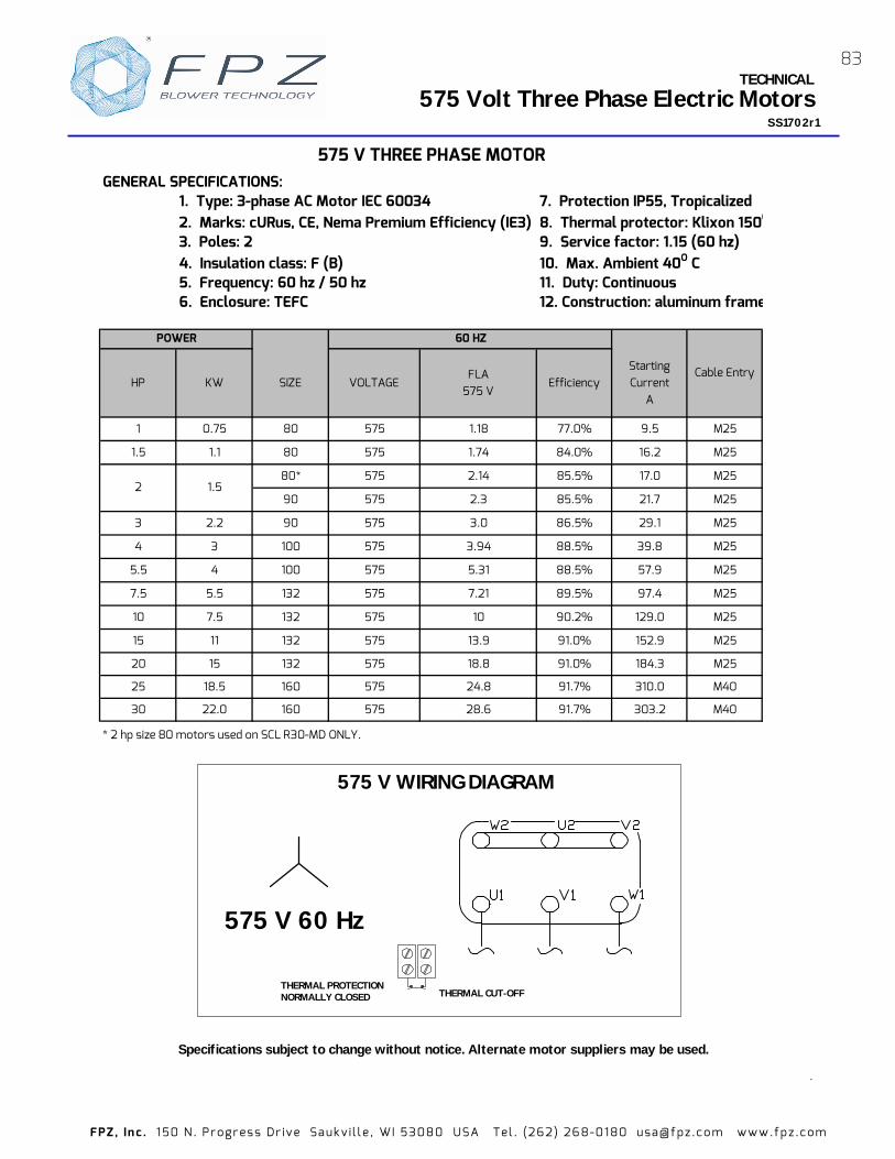
FPZ , In c . 1 50 N . Pr ogr es s Dr ive Sa uk v i l l e , WI 5308 0 USA Tel . (262 ) 26 8-01 80 usa@ fpz .c o m www.fp z .c om
.
Specifications subject to change without notice. Alternate motor suppliers may be used.
TECHNICAL
SS1702r1
THERMAL PROTECTION NORMALLY CLOSED THERMAL CUT-OFF
575 Volt Three Phase Electric Motors
575 V 60 Hz
575 V WIRING DIAGRAM
GENERAL SPECIFICATIONS:1. Type: 3-phase AC Motor IEC 60034 7. Protection IP55, Tropicalized2. Marks: cURus, CE, Nema Premium Efficiency (IE3) 8. Thermal protector: Klixon 150O 3. Poles: 2 9. Service factor: 1.15 (60 hz)4. Insulation class: F (B) 10. Max. Ambient 40O C5. Frequency: 60 hz / 50 hz 11. Duty: Continuous6. Enclosure: TEFC 12. Construction: aluminum frame
HP KW SIZE VOLTAGEFLA
575 VEfficiency
Starting Current
A
1 0.75 80 575 1.18 77.0% 9.5 M25
1.5 1.1 80 575 1.74 84.0% 16.2 M25
80* 575 2.14 85.5% 17.0 M25
90 575 2.3 85.5% 21.7 M25
3 2.2 90 575 3.0 86.5% 29.1 M25
4 3 100 575 3.94 88.5% 39.8 M25
5.5 4 100 575 5.31 88.5% 57.9 M25
7.5 5.5 132 575 7.21 89.5% 97.4 M25
10 7.5 132 575 10 90.2% 129.0 M25
15 11 132 575 13.9 91.0% 152.9 M25
20 15 132 575 18.8 91.0% 184.3 M25
25 18.5 160 575 24.8 91.7% 310.0 M40
30 22.0 160 575 28.6 91.7% 303.2 M40
* 2 hp size 80 motors used on SCL R30-MD ONLY.
Cable Entry
575 V THREE PHASE MOTOR
POWER 60 HZ
2 1.5
83

FPZ , In c . 1 50 N . Pr ogr es s Dr ive Sa uk v i l l e , WI 5308 0 USA Tel . (262 ) 26 8-01 80 usa@ fpz .c o m www.fp z .c om
PressureOrifice Diameters - Inches
Pressure " H2O 1/32 1/16 1/8 3/16 1/4 5/16 3/8 7/16 1/2 5/8 3/4 1
1 0.0 0.1 0.2 0.5 0.9 1.4 2.0 2.7 3.5 6 7.8 14 22 31 43 56 70 87 105 125
2 0.0 0.1 0.3 0.7 1.2 1.9 2.8 3.8 4.9 8 11 20 31 44 60 79 100 123 149 177
3 0.0 0.1 0.4 0.8 1.5 2.4 3.4 4.6 6.0 10 14 24 38 54 74 96 122 150 182 217
4 0.0 0.1 0.4 1.0 1.7 2.7 3.9 5.3 7.0 11 16 28 43 63 85 111 141 174 210 250
5 0.0 0.1 0.5 1.1 1.9 3.0 4.4 6.0 7.8 12 18 31 49 70 95 124 157 194 235 280
10 0.0 0.2 0.7 1.5 2.8 4.3 6.2 8.4 11.0 18 25 44 69 99 135 176 222 275 332 395
15 0.1 0.2 0.8 1.9 3.4 5.3 7.6 10.3 13.4 21 30 54 84 121 165 215 272 336 407 484
20 0.1 0.2 1.0 2.2 3.9 6.1 8.7 11.9 15.5 25 35 62 97 140 190 248 314 388 469 559
25 0.1 0.3 1.1 2.4 4.3 6.8 9.8 13.3 17.3 28 39 69 108 156 212 277 351 434 525 624
30 0.1 0.3 1.2 2.6 4.8 7.4 10.7 14.5 19.0 30 43 76 119 171 233 304 385 475 574 684
35 0.1 0.3 1.3 2.9 5.1 8.0 11.5 15.7 20.5 33 46 82 128 185 251 328 415 513 620 738
40 0.1 0.3 1.4 3.1 5.5 8.6 12.3 16.8 21.9 35 49 88 137 197 268 351 444 548 663 789
45 0.1 0.4 1.5 3.3 5.8 9.1 13.1 17.8 23.2 37 52 93 145 209 285 372 470 581 703 836
50 0.1 0.4 1.5 3.4 6.1 9.6 13.8 18.7 24.5 39 55 98 153 220 300 392 496 612 740 881
55 0.1 0.4 1.6 3.6 6.4 10.0 14.4 19.6 25.7 41 58 103 160 231 314 411 520 641 776 924
60 0.1 0.4 1.7 3.8 6.7 10.5 15.1 20.5 26.8 43 60 107 167 241 328 429 542 670 810 964
65 0.1 0.4 1.7 3.9 7.0 10.9 15.7 21.3 27.9 45 63 111 174 251 341 446 564 697 843 1003
70 0.1 0.5 1.8 4.1 7.2 11.3 16.3 22.1 28.9 46 65 116 181 260 354 463 585 723 874 1041
75 0.1 0.5 1.9 4.2 7.5 11.7 16.8 22.9 29.9 48 67 120 187 269 366 479 606 748 905 1077
80 0.1 0.5 1.9 4.3 7.7 12.1 17.4 23.6 30.9 50 70 124 193 278 378 494 625 772 934 1112
85 0.1 0.5 2.0 4.5 8.0 12.4 17.9 24.4 31.6 51 72 127 199 285 390 509 644 795 962 1145
90 0.1 0.5 2.0 4.6 8.2 12.8 18.4 25.1 32.7 53 74 131 204 294 401 524 663 818 990 1178
95 0.1 0.5 2.1 4.7 8.4 13.1 18.9 25.7 33.6 54 76 134 210 302 412 538 680 840 1016 1210
100 0.1 0.5 2.2 4.9 8.6 13.5 19.4 26.4 34.5 55 78 138 215 310 422 551 698 861 1042 1241
105 0.1 0.6 2.2 5.0 8.8 13.8 19.9 27.0 35.3 57 79 141 221 318 432 565 715 882 1068 1271
110 0.1 0.6 2.3 5.1 9.0 14.1 20.3 27.6 36.1 58 81 144 226 325 442 578 731 903 1092 1300
1 psi = 27.68" H 2O discharge coeffecient = 0.65 Air Temperature = 70 deg F Airflow in CFM
VacuumOrifice Diameters - Inches
Vacuum " Hg 1/32 1/16 1/8 3/16 1/4 5/16 3/8 7/16 1/2 5/8 3/4 1 1-1/4 1-1/2 1-3/4 2.0 2-1/4 2-1/2 2-3/4 3
0.5 0.0 0.1 0.6 1.3 2.2 3.5 5.1 6.9 9 14 20 36 56 81 110 144 182 225 272 324
1 0.0 0.2 0.8 1.8 3.1 4.9 7.1 9.6 13 20 28 50 79 113 154 202 255 315 381 453
2 0.1 0.3 1.1 2.5 4.4 6.8 9.8 13.0 17 27 39 70 109 157 214 280 354 437 529 629
3 0.1 0.3 1.3 3.0 5.2 8.2 11.8 16.0 21 33 47 84 131 189 257 336 425 525 635 756
4 0.1 0.4 1.5 3.3 5.9 9.3 13.4 18.0 24 37 53 95 148 214 291 380 481 594 718 855
5 0.1 0.4 1.6 3.7 6.5 10.0 14.6 20.0 26 41 58 104 162 234 318 416 526 650 786 936
6 0.1 0.4 1.7 3.9 7.0 11.0 15.7 21.0 28 44 63 111 174 251 341 446 564 696 842 1002
7 0.1 0.5 1.8 4.1 7.3 11.0 16.5 22.0 29 46 66 118 184 264 360 470 595 735 889 1058
8 0.1 0.5 1.9 4.3 7.7 12.0 17.3 23.0 31 48 69 123 192 276 376 491 621 766 927 1104
9 0.1 0.5 2.0 4.5 7.9 12.0 17.8 24.0 32 50 71 127 198 285 388 507 642 792 959 1141
10 0.1 0.5 2.0 4.6 8.1 13.0 18.3 25.0 33 51 73 130 203 293 398 520 659 813 984 1171
11 0.1 0.5 2.1 4.7 8.3 13.0 18.7 25.0 33 52 76 133 207 298 406 530 671 829 1003 1193
12 0.1 0.5 2.1 4.7 8.4 13.0 18.9 26.0 34 52 76 134 210 302 412 538 680 840 1016 1210
13 0.1 0.5 2.1 4.8 8.5 13.0 19.1 26.0 34 53 76 135 212 305 415 542 686 847 1025 1219
14 0.1 0.5 2.1 4.8 8.5 13.0 19.1 26.0 34 53 76 136 212 306 416 544 688 849 1028 1223
15 0.1 0.5 2.1 4.8 8.5 13.0 19.1 26.0 34 53 76 136 212 306 416 544 688 849 1028 1223
1" HG = 13.6" H2O discharge coeffecient = 0.65 Air Temperature = 70 deg F Airflow in CFM
Airflow Through an OrificeTECHNICAL
1-1/4 1-1/2 1-3/4 2.0 2-1/4 2-1/2 2-3/4 3
84