[K - Defense Technical Information Center In the ribs did drop, but, it remained sufficiently high...
22
. . 4 I IC -> '-V . A 4'4 .1 . -u' **. £ . Er I I . .1 .1 Reproduced From * -- Best Available Copy r A . [K
Transcript of [K - Defense Technical Information Center In the ribs did drop, but, it remained sufficiently high...

. .
4
I
IC ->
� '-V
.
A
4'�4
.1
.� -u�'
*�*.
£ .
Er I
I � .
�
.1
.1
Reproduced From
* --� Best Available Copy
r
A .
[K

1 I National DefenseDefence natonaie
AN EVALUATION OF THE TRELLEBORGINFLATABLE MEDICAL TENT
by
Brad CainEnvironmental Protection Section
Protective Sciences Division
DTIC., ELECTED
,.JUN 3 85
B
DEFENCE RESEARCH ESTABLISHMENT OTTAWATECHNICAL NOTE 84-20
PCN December 198414810 -I TIOlSTATEMENT Ottawa
SApproved' tot public releasO
Ditribution unlimited
,..•................................ . . -.-........-"

ABSTRACT
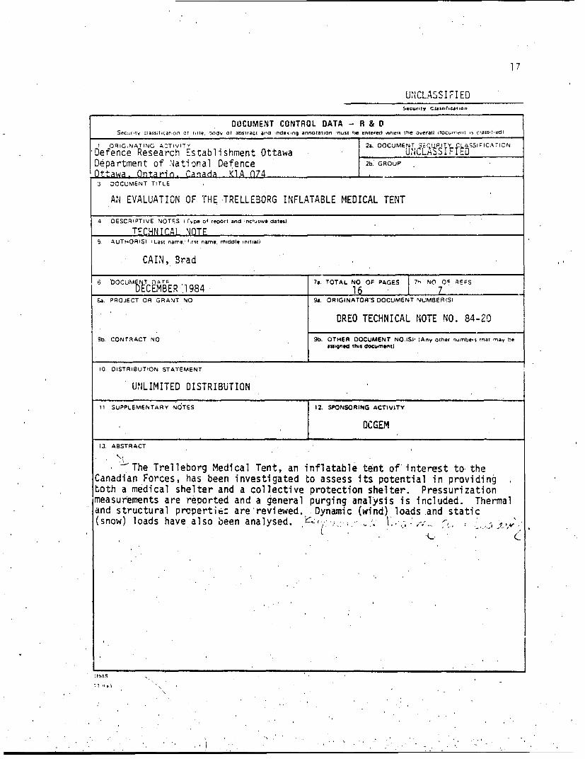
The Trelleborg Medical Tent, an inflatable tent of interest tothe Canadian Forces, has been investigated to assess its potential inproviding both a .medical shelter and a collective protection shelter.Pressurization measurements are reported.and a general purging analysis isincluded. Thermal and structural properties are reviewed. Dynamic (wind)loads and static (snow) loads have also been analysed.
RESUME
La tente midicale gonflable Trelleborg, qul prisente un int~ritpour les Forces canadlennas, a Wt4 examinee afin de diterminer lapossibilit6 de .l'utiliser comme abri mfdical et comme abri de protectioncollective. Les mesures de la pression 'interne. ainsi que les r6sultatsd'une analyse de T'air fvacug sont .notis. Les-propriftis' thermiques etstructurales de la tente sont examinges, et on analyse aussi des cl."--ges'cynamiques (vent) et des charges statiques (neige).
DTIC TA-` ElJ
i-...............
A, ':•/ ............CZ,
.t
' • , . . . .. ' • -. 7 .. . . . . .. . ", , i

1.0 INTRODUCTION
This report describes an evaluation of the Trelleborg InflatableMedical Tent (1) which is being considered for use by the Canadian Forces(CF),. both as a mobil'e medical shelter and as a collective protectionshelter. The tent is a semi--cylindrical shelter, made of a polyvinylchloride (PVC) coated fabric, supported by four inflatable ribs (Figure 1).The basic concept is that a section of this tent be equipped with anairlock and a liquid-chemical repelling fly so that it could be used as achemically secure' shelter. The tent may be erected in modular form,including as many sections or airlocks as required.
This study notes some of the physical properties of the tent,advances procedures for establishing the pressurization capabilities andths heating properties of tents, makes general comments on the tent andinvestigates some aspects of the tent's incurred loads. A discussion ofpurging of the tent is a.lsn presented.
2.0 GENERAL OBSERVATIONS
2.1 PHYSICAL PROPERTIES
'Some of the important physical characteris'tics of the TrelleborgMedical Tent are listed in Table I.,
The PVC coated material provides a durable covering 'which iseasily cleaned with soap and water, kerosene or acetone, The generalconstruction of the tent appears sound, based on observations made at theDREO Tent Testing Facility, however, extensive field trials on the tentmust be held before any definitive conclusion can be made in this area.

U. w
00
IL)JL
zC
_______________________________________cc__________ >

3
TABLE 1
Physical Characteristics of the Trelleborg MedicalTent and Support Equipment (1)
Medical Tent
Length 7.25 mWidth 5.20 mHeig;tt (Maximum) 2.60 mFloor Area 37.7 sq.mNumber of Doors 2Door Height 2.15 mDoor Width 1.88 mNumber of Rib Spacers 6Packed Weight (With Spacers) 227 kgPacked Volume (Without Spacers) 1 cu.mPacked Spacer Volume 0.024 cu.m
Support Equipment
Air Presstre Fan
Power 700 WVoltagx. 230 VacWeight 20 kgPacked Volume 0.056 cu.m
Equipment/Re air Kit
Weight 180 kgVolume .0.5 cu.m

4
2.2 ERECTION AND STRIKING
The erection and striking of the tent is easily accomplished,even by novices. The instruction manual is short, to the point and clearin its instructions. With this manual or a small amount of instruction thetent may be quickly erected and put in use. Table 2 lists some typicalerection and striking times as performed by personnel familiar with thetent.
It was .found that three to five men werp adequate for theefficient erection of the tent. As the tent weighs approximately 250 kg,it would be most convenient if the tent were to be unloaded from thetransport vehicle as close to its final destination as possible. With someeffort, four men can. carry the tent several metres.'
It was found that most of the air trapped in the ribs during thestriking procedure could be expelled by rolling the tent along Its lengthtowards the open air-valves. When the tent was then unrolled, it foldedmuch more easily and more compact than when this step was omitted. Walkingon the deflated ribs was 'not found to be particularly effective forexpelling the trapped air, and this practice runs the risk of puncturingthe rib. Zippering the doors shut prior to striking the tent also madepacking of the tent somewhat easier.
2.3 INFLATABLE RIBS
The electric inflation fan used to inflate the supporting' ribs ofthe tent ooerates on 220 Vac at 700 W. It delivers 15 I/s maximum andattains a maximum pressure of 18 kPa. At this rate, a single, rib requiresapproximately. one and one-half minutes to inflate fully. It may be.convenient to supply an inflation fan which can operate with otherelectrical power sources such as 48 Vdc (vehicle battery) or 110 Vac. Apressure regulator could be used which, when used with air compressorscurrently available on some CF vehicles, would, supply air at a maximumpressure of 18 kPa.
There was air loss from, the ribs, but it was founa to berelatively slow. When the tent was left unattended for several days, thepressure In the ribs did drop, but, it remained sufficiently high to

5
"TABLE 2
Typical Erection and Striking Times of the TrelleborgMedical Tent Under Ndeal (Summer) Conditions(Terms in brackets refer to manual inflation)
Action Tima(min)
Erection - Four Man Crew,
Unpacking 4Inflation: Electric fan 6 (20)Inserting Floor 1Stake and Guy 2
Subtotal 13 (27)
Connection/Erection of the ..Black-out Section
Total Time Required 18 (3M
Erection - One Man Crew
(Steps as above)Total Time Required 45
Foot-pump Inflation/Tube 5
Striking - Four Man Crew
Removal of Floor 1Deflation Time/Tube 3Removal of Trapped Air 3Folding - Tent and Floor 5Packing - Tent and Floor 3Packing - Poles 1Packing - Accessories 1
Total Time Required 17
support the weight of the tent. Under adverse weather cond 4tions, such asheavy winds or snow-fall, it is recommended that the rib pressure bemaintained at the nominal operating pressure of 18 kPa to ensure optimumperformarce of the tent. To maintain this condition, the ribs may requiretopping-up to operating pressure perhaps as often as every tnree days.This time will depend upon the condition of the valve seal and theintegrity of che inflatable rib inner-tube. Changing ambient tcmperaturesmay cause some fluctuation in the rib pressure, athough it is not expectedto be an important factor. A faulty valve or a puncture in a ribinner-tube could cause the rib to deflate more rapidly than was observedwhile the tent was under test at DREO.
As depicted in Figure 1, the inflated ribs are held apart byaluminum spacer bars. It was found that, when a rib was deflated, theadjacent spacer bars fell out of place. This is potentially hazardous topersonnel or equipment located beneath the spacer bars. It is recommendedthat a safety strap arrangement be used to keep the spacer bars fromfalling should a rib deflate.
Guy-ropes, although not essential for the erection or u3e of thetent, may be important in some situations. It was found that if one of thecenter ribs, deflated, the end-guys would hold the tent erect andfunctional. In heavy winds, especially for an empty tent, the guys may benecessary to secure the tent to the ground. During pressurization tests,the tent inflated and the ribs'were lifted off of the -ground entirely.' Inthis situation, lateral guys may be necessary to keep the edges of the tenton the ground. A securely guyed fly-sheet may also be of use in keepingthe tent on the ground.',
It was found that, even after limited use, the plastic fastenersused to connect tent sections together had worn significantly. This wasprimarly due to friction caused when' the rope used to secure the fastenerwas 'pulled through the connector. If the rope fastener is to be used, itmay be necessary to use metal ;omponents. Alternatively, each fastenercould be supplied with its own key which would replace the rope. This typeof, fastener may even facilitate assembly. Fasteners of this type arecurrently under study within the Directorate of Clothing GeneralEngineering and Maintenance (DCGEM).
3.0 0RESSURIZATION TESTS
A timple procedure was used for establishing the pressurizationcapabilities of' tents designated for use wnile subjected to an internal,over-pz'essur.. Pressurization tests were performed on th'e'Trelleborg tentusing an electrically powered Herman-Nelson Heater/Blower to supply the

77
7
air. The air flow-rate was measured using an orifice plate flowmeter withD-1/2D pressure taps and an inclined manometer. Flow coefficients for thaorifice plate flowmeter were calculated according to standard practices(2). A "flow resistance" was calculated for the tent based on thefollowing relationship:
R =Pm/Q []
where, R is the flow resistance (Pa.s/in 3)Pm is the mean tent pressure (gauge) (Pa)Q is the volume flowrate into the tent (m3/s)
The results of the tests are summarized in Table 3. In Section Aof Table 3, the tent was not modified in any way. Vents were closed bypulling the drawstrings only. Chimney hole covers were closed, as were thedoor zippers.
In Section B of Table 3, the tent was modified slightly. Forthese tests, ail vents were tied off and sealed using tape. Chimney holeswere taped shut dnd covered with plastic. One of the doors into the tentwas sealed as well as could be achieved by tiping over the zipper andweighting the bottom flap. The other door was weighted at the bottom only.Attempts to seal the tent completely were only partially successful as itis difficult to find an adhesive wh-ah will stick to PVC temporarily andyet form a good seal.
Included in Table 3 is the time required for the tent to reachthe steady-state mean gauge pressure from the initial, ambient pressure.This quantity is denoted by the' symbol Tss.
The variations in the data of Section B in Table 3 are due inpart to the difficulty in maintaining a good seal around entrances' to thetent., However, It can be seen that even though the seal in the tent wasincomplete, there was a substantial gain 'in the flow resistance of the tentwhen the modification for Section B were made. The mean fiow resistance ofthe "sealed" tent was approximately 369 (Pa.s/m3 ) compared with 126(Pa.s/m3 ) of the standard tent. It is expected that when'the tent is .moreeffectively sealed, the flow resistance will reach avalue of approximatel'y416 (Pa.s/m3 ). This is the estimated flow resistance for the tent with twodoors, closed by zippers around the entire door periphery, and only onevent through which air is supplied to the tent.
When the tent experienced the larger overpressures of Section B,the tent inflated, lifting off the ground near the wall by as mucn asthirty. centimeters. At that point, the tent was held erect by theoverpressure alone. This action may cause problems which may possibly beremedied'by usi'ng guy-ropes as noted in the previous section.

8
TABLE 3
Results of Pressurization Tests on theTrelleborg Medical Tent
Air Mean Flow TssFlow-rate Pressure Resistance
(m3/3) (Pa) (Pa.s/m3 ) (min)
SECTION A
0.2208 28.61 129.51 120.2680 33.59 125.33 3.50.2905 36.08 124.20 3.5
SECTION B
0.2167 69.66 321.46 40.2729 118.18 433.05 2.50.2868 100.75 351.33 2

9
It was found that the Black-Out Section, an additional section oftentage which can be added to the medical tent, would not hold asignificant overpressure in its current form. This is prfimarily due to theclosure system of the door. A more effective "air-lock" could be made fromthe Black-Out Section if a more secure closure sys~tem were to be used.
If two main sections of tentage are to be used in modular form,several recommendations are in order:
1) To maintain sufficient overpressure and to minimize purge time, eachsection of tentage may require its own source of filtered air.
2) To minimize the intrusion of external air into the tent at theirjuncture, the tents should be joined at the connection flap aroundthe door rather than at the flap around the end wall. This wouldproduce a connection with the smallest seam area through -whichou.tside air may enter.
3) The region around the junction of the two tents must be pressurizedto prevent intrusion of chemicals into. the tent. This may be.accomplished by ensuring that one of the two doors at the junction ofthe tents is open.
The following modifications would, improve the pressurizationperformance of a single tent section:
1) All but one or two air vents and all chimney holes should beoliminated..
2) Power cable tunnel vents should be replaced with sealed electricaljunction boxes mounted in the tert.wall.
3) If the rear door on the secure section of the' tent Is not required,it should be elimitiated or at least be prqvioea with improved meansfor further .ealing against air-ler-kage.
4) All doors should include a fastener across the bottom which wouldseal the doors a-% the floor.
if a tent is modified as noted above, it is expected that it willhave a flow resistance of approximately 416 (Pa.s/m3 ) as previously.calculated. Thus, a Herman-Nelson, which is capable of deli.vering air atflow rates between 0.229 and 0.458 (m3/s) would provide an overpressure of,between 95 and 190 Pa respectively. The Trelleborg blower, which ,delivers0.611 (m3 /s) would provide an overpressure of 254 Pa. 'These estimatesassume that the resulting overpressures are withi'n the delivered headc;-pabilities of the fan.

• • e10
t. *\.,
4.0 PURGING
Purging of the interior of airlocks and tents may be required to!.,•remove hazardous chemicals which have contaminated the interior. Purgetime for air-locks, and entire tents depends upon several parameters. Abrief and simplified mathematical analysis of the purging processing is• included here.
Initially it is, assumed that any contaminant which enters theair-lock is uniformly distributed throughout the entire volume Thegoverning differential equation for this problem is:
d v -C xQ [2)dt
where, C is the concentration of the contaminant in the air-lock¾ •as a function of time,
t is the time from the start of purging,V is the volume of the air-lock,Q is the rate at which filtered air is being supplied to
the air-lock.
The solution for purging time from this differential equation is:
t = (V/Q) x ln(Ci/C) [3]
where, Ci is the initial concentration of the contaminant in the air-lock.|i
Experimental investigation indicates that equation 3 should beamended to:
t (V/(Q. x kW) x ln'(Ci/C) [4]
where k is an empirically determined constant which compensates for unequalmixing of the fresh, incoming air and the contaminated, internal air. The
1. It, •
-.-...
,

5°4
value of k has been reported to bewithin the range 0.35, to 0.39, but thisvalue may be dependent upon the shelter size and shape (3).
By specifying a safe concentration level "C", and knowiing the airflow-rate into the tent and the tent volume, the required purge time can becalculated for the tent for any initial concentration using equation 4.
5.0 HEATING
One section of the Trelleborg Tent was instrumented withthermistors and heated with forced air electric heaters to determire itsheating properties. Analysis of the data (4) indicates that the tent has atemperature rise per Watt of heat input of 0.0074 ± 0.001 C/W over the windtI speed interval 0.5 to 4.0 m/s. The value' of the temperature rise per Watt
_ was found to decrease approximately linearly with increasing wind speedfrom 0.0086 C/W at 0.5 r'./s to 0.0057 C/W at 4.0 m/s. Heat loss through thefloor varied from 2 to 7% of the total heat loss from the tent. This heat"loss will be a function of several parameters including ground temperature,air temperature and wind speed. It is expected, based on experiments withother tents (4), that a single layer, fabric liner would' approximately"double the relative temperature rise per Watt of heat'input to the tent.
6.0 'STRUCTURAL
As 'theTent Research Facility at DREO is not currently equippedto Investigate the structural capabilities of tents, no direct measurementsof loading carrying capacities were made. Estimates of the incurred windloads are presented which are based upon work performed for the Natick"Laboratories (5,6)p Estimates of the load carrying capabilities of tiearches may be obtained following the procedures of Steeves (7). Some
C . . -.

12
general observations of the structural capabilitieis of the tent are madeand calculations pertaining to the enhanced load carrying capacity of apressurized tent are presented.
6.1 WIND LOADS
During one particularly violent wind storm (gusts of 90 km/hrwere experienced), the leading edge of one of the tents lifted, pulling thepegs from the ground. The tent then commenced to roll away, driven by thewind. The tent sustained only minor damage to the oute., shell before itcame to rest. It may therefore be neces'sary to increase the size of theskirt around the edge of the tent and to weight the skirt with soil or snowta prevent lifting of the tent during heavy winds. It is expected that thetent will, be stable in winds up to approximately 100 km/hr if thisprocedure is followed. It is recommended that the tent be put to trial inan area which regularly experiences heavy, winds to confirm the tent'scapabilities.
Estimates of the wind loads on the tent may be made by knowingthe wind speed and several other physical parameters. The generalmathematical relationship is:
F CpAV 2/2 ES)
where, F is the load or force on the tent,C is the load coefficient (drag or lift),p is the air density,V is the air velocity,A -Is the tent floor area.
-Studies conducted at U.S. Natick Labs (5,6) indicate that themaximum drag, coefficient for structures similar to the Trelleborg tent isbetween 0.2 and,-0.33. Maximum lift coefficients,'were found to be 0.43 (5)and 0.55 (6).
Anchor and guy-line load coefficients. may be used with equation•5] to determine the aerodynamic load placed on the 'anchor or guy-line.Note that if the tent is subjected to an, overpressure, the load placed onthe anchors ana guy-lines must be calculated from the vector sum of' theaerodynamic loads and the internal pressure loads.
If the tent is to be used without guy-lines, Dietz (6) recommendsusing a maximum anchor load coefficient Ca! of 2.05. This means that the
K- - - . .... : .. •.. .. ... . . . . . .... ; ... ' .. * *. '~ **.. . . .. . . . . '. . .
j 13
maximum load carried by each anchor will be:
m =Cal pAV 2/2N [6]
where N is the number of anchors used around the periphery of the tent.
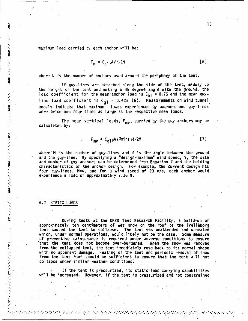
If guy-lines are 'attached along the side of the tent, midway upthe height of the tent and making a 45 degree angle with the ground, theload coefficient for the mean anchor load is Cbl = 0.75 and the mean guy-line load coefficient is CgI = 0.425 (6). Measurements on wind tunnel
models indicate that maximum loads experienced by anchors and guy-lineswere twice and four times as large as the respective mean loads.
The mean vertical loads,'Fmv, carried by the guy anchors may becalculated by:
. Fmv CgI pV 2sin(e)/2M [7]
where M is the number of guy-lines and 6 is the angle between the groundand the guy-line. By specifying a "design-maximum" wind speed, V, the sizeiand number of guy anchors can be determined from Equation 7 and the holdingcharacteristics of the anchor design. For example, the current design hasfour guy-lines, M=4, and for a wind speed of 20 m/s, each anchor wouldexperience a load of approximately 7.36 N.
6.2 STATIC' LOADS
During tests dt the DREO Tent Research Facility, a build-up ofSapproximately ten centimeters of wet snow on the roof of the Trelleborg
tent caused, the tent to collapse. The tent was unattended and unheatedwhich, under normal operations, would likely not be the case. Some measureof preventive maintenance is required under adverse conditions to ensure'that the tent does not become over-burdened. When the snow was removedfrom the collapsed tent, the tent immediately rose back to its normal shape"with no apparent damage. Heatingof the tent and periodic removal of snowfrom the tent roof should be sufficient to ensure that the tent will not
". collapse under similar weather conditions.
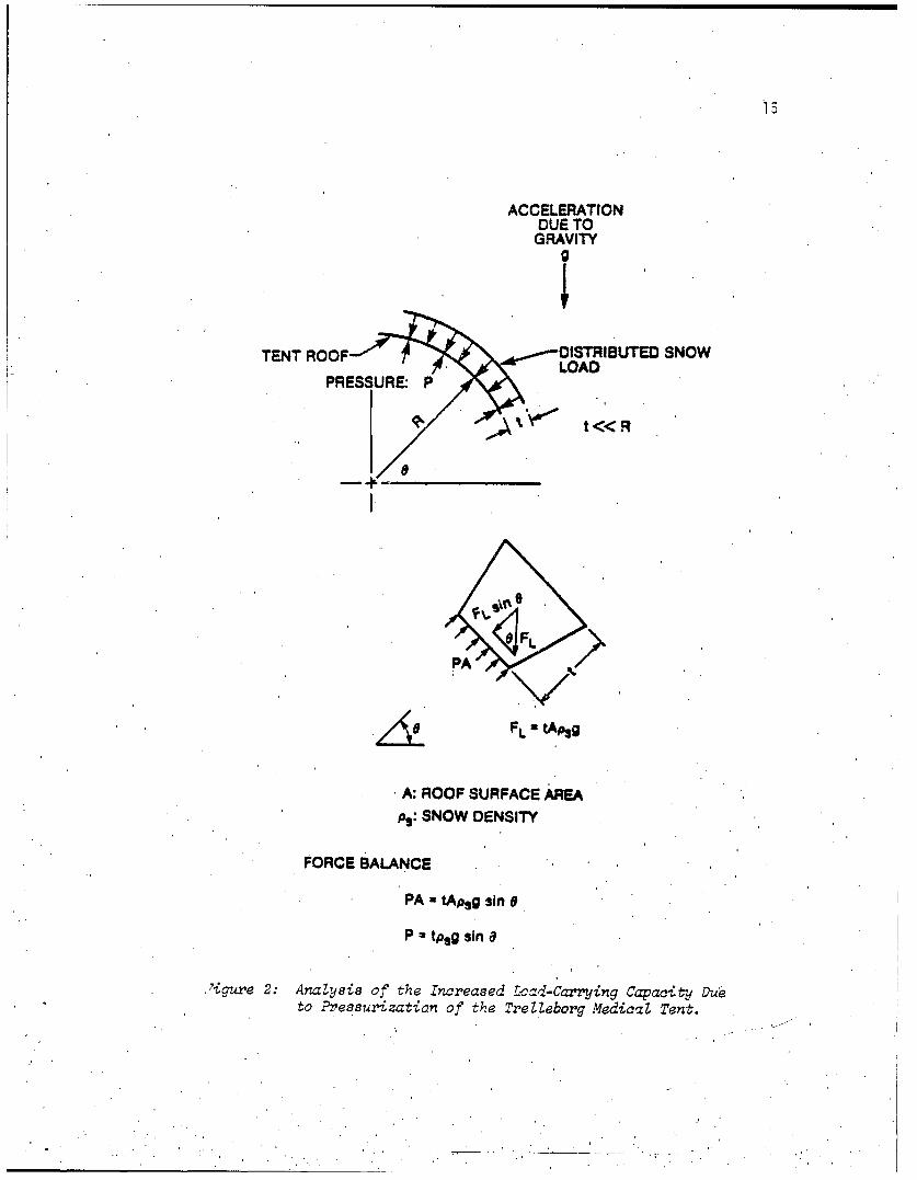
If the tent is pressurized, its static load carrying capabilitieswill be increased. However, if the tent is pressurized and not constrained
• ... .............-...- •• .. .*• -; . 7'°°'.'. 'o".. .. ".-.... ... '.°..i. ow..... .°•...o-. o°.'o. . '• " *. .° " *,,. "• * *_-

14
verticaly, the tent will experience a larger lateral wind load. Theincrease in the static load carrying capabilities of a pressurized tent canbe considerable. As an example, Figure 2 shows a hypotietical build-up of.snow on the roof ofa pressurized tent. The calculations indicate that forevery ten Pascals of overpressure in the tent, one additional centimeter of"standard snow" may accumulate on the tent without adding an additionalload to the ribs.
7.0 SUMMARY AND CONCLUSIONS
Tne Trelleborg tent, although not without some problems, appearsto be a very good shelter. The tent is easily and quickly erected, even bynovice users; it is easily cleaned;-it is durable; if suitably anchored, itis tolerant of moderately high winds. The tent has a flow resistance of128 Pa.s/m3 when an overpressure is applied and it is predfcted that amodified version of the tent which eliminates many of the unnecessary ventswill have a flow resistance of 416 Pa.s/m3.
Becaise of its weight and size, the tent should be transported by'vehicle. It is possible but awkward, for the tent to be moved by four menin its packed state for several meters. The tent may be readily moved whenerected to facilitate moduldr expansion.
The mean internal temperature rise above ambient per Watt of heatinput for the tent is approximately 0.0074 C/W. This value was observed tovary linearly from 0..0086 C/W at a wind speed of 0.5 m/s to 0.0057 C/W at4.0 m/s. Heat loss to the floor was found to represent only 2 to 7% of the'total heat loss of the tent. It is expected that a liner consisting of asingle layer of cloth' would approximately doable the mean internaltemperature rise per Watt of heat input from the tent.
The tent require's mini'mal maintenance, unde'r adVers-e weatherconditions to ensure that snow accumulation or wind loads do not becomeexcessive. It is expected, that superior static load carrying capabilitieswould be achieved by using additional guying and by applying overpressuresto the tent.
15
ACCELERATIONDUE TO
GRAVITY
TENT ROOF D-STRIBUTED SNOW
PRESSURE.O P
4 L
PA
FLU tAPg
A: ROOF SURFACE AREA
ps: SNOW DENSITY
FORCE BALANCE
PA tApsg sin 0
P u tpsg sin a
'igure 2: Analysis of the Increased L-2ad-Carrying Capacity Duieto Pressurization of the TrelZeborg Medical Tent.

8.0 REFERENCES
1. Trelleborg AB, Protective Products Division, Box 501, S-231 01Trelleborg, Sweden.
2. Baumeister, T., ed.; Marks' Standard Handbook for MechanicalEngineers, 8th Ed.; McGraw-Hill Book Co., roronto, 1978.
3. Sturk, J.0., private communications.
4. Cain, B., An Initial Investigation of the Heating Properties ofCorical Tents, DREO Technical Note No. 83-32.
5. Bolt, Beranek and Newman, Inc., Measurement of Wind Loads on Large-Scale Air-Supported Shelters. Natirk Technical Report 75-101-AMEL,United States Army, Natick Development Center, Natick, Mass., 1975.
6. Dietz, A.E. et al, Design Manual for Ground-Mounted Air-SupportedStructures (Single 'and Double-Wall) (revised). Natick TechnicalReport 69-59-GP, United States Army, Natick Laboratories, Natick,Mass., 1969.
7. Steeves, E.C., Strtuctural Behavior of Pressure-Stabilized Arches,Natick TeChnical Report TR-78/018, United States Army, Natick Researchand Development Command, Natick, Mass., 1978.
UNCLASSIFIEDsecurity clasid'"tJUan
DOCUMENT CONTROL DATA -R & D'Secwtty class;ftcatoi, 01 utle. 00oy of abstract antd inoexing annotation nrust hte entered wterer thre a~era1( cloct.,mew s 03sstfed)
Defe~n~ce Research Establishment OttawaLASFE
4 DESCRIPTIVE NOTFS (rype oft rco~rt and incl-jsive date%)
TECHNICAL NOTF5. AUTHOR IS) I Last natme. first name. middle initial)
CAIN, Brad
6- bocum1bNTC~E 1984 7a. TOTAL NO. OF PAGES 7"i NO.OF REFS
Fa. PROJECT OR GRANT NO 9.ORIGINATOR'S DOCUMENT NU.MBER(S)
DREO TECHNICAL NOTE NO. 84-20
9b. CONTRACT No 9b. OTHER DOCUMENT NOASP (Any other numbers that may beassigned this document)
t0. DISTRIBUTION STATEMENT
UNLIMITED DISTRIBUTION
11 SUPPLEMENTARY NO6TES 12. SPONSORING ACTIV.ITY
DCGEM
11. ABSTRACT
~The Trelleborg Medical Tent, an inflatable tent of interest to theCanadian Forces, has been investigated to assess its potential in providingboth a medical shelter and a collective protection shelter. Pressurizationmeasur~ements are reported and a general purging analysis is included. Thermaland structural propertie: are'reviewed. Dynamic (wind) loads an-d static(snow) loads have also been analysed.K <'>
7 . .

UNCLAr•!SF1EDSaturity Classification
KEY WORDS
I N FLATABLE
TENT
MEDICAL
HEATING
LOADING
PRESSURIZATION
PURGING
INSTRUCTIONS
i. ORIGINATING ACTIVITY, Enter the name and address of the 9b. OTHER DOCUMENT NUMBERISI: If the document has beenorganization issuing the document. assigned any oarter document numbers (either by the originator
or by the sponsor,. also enter this number(ls).2a. DOCUMENT SECURITY CLASSIFICATION. Enter the Overall
security classificatiOn of the document including soicial warning 10. DISTRIBUTION STATEMENT: Enter any limitations onterms whenever applicable. -further disseminetion of the document, other than those impolsed
by security classlication. using standard statements such as.2b. GROUP' Enter security reclassitfication grout; number. The three
grOups are dot-ned in Appendix 'M'ot the ORB Security Regulations. (1) "Qualified requesters may obtain copies of thisdocument fr',)m their defence clocumenstion center."
3. DOCUMENT TITLE Enter the complete document title in allCapical oltters. Titles in all cases should be unclassified. If a (2) "Announcement and dissemination of this documentsufflciently dascriptive title cannot beis selected withOut classifi- is not authorwied wvithout prior approval fromcation. show title classification with the usual one-capital- letter originating activity."abbreviation in poarentnes" immediately following the title.
11. SUPPLEMENTARY NOTES. Use for additional explanatory4. DESCRIPTIVE NOTES. Enter the category of document, e.g. notes.
technical report, technical note or technical letter. If appropri-ate. enter tee type of document, e.g. interim. progress, 12. SPONSORING ACTIVITY: Enter the name of the departmentalsummery, annual or fina. Give the inclusive dates when a prolect office or laboratory sponsoring the researct- andspecific reporting period is covered. development. Include address.
5. AUTHOR(S): Enter the namefs) of authorlil as shownoi-or --- 13. ABSTRACT: Enter an abstract giving a brief and factualin the document. Enter last name, first name' middle initial. summary of the document, even tpough it may also appearIf military, show rank. The name of the princlpal author is an elsewhere in the body of the document tself. It is highlyabsolute minimum requirement. desirable that the abstract of cfassifed documents :a unclassi-
fied. Each oaragraph of the abstract shall end with anE. DOCUMENT DATE: Enter the date (month. year) of indication of the security classification of the information
Estab~hIhment approval for publication of the document. in the paragroh lunless the document itself is uncltassifiedlrepresented as (TSI, IS),: (CI. (RI. or 1U.
7a. TOTAL NUMBER OF PAGES. The total osa count shouldfollow normal pagination procedures. i.e., enter the number The length of the abstract should be limited to 20 tingle-spacedof pages containing information. standard typewritten lines. 71 1 ncnes long.
7b. NUMBER OF REFERENCES: Enter the totl number of 14. KEY WORDS, Key words are technically meaningful terms orreferences cited in the document. short phrases that characterize a document and could be helpful
in cataloging the document. Key words should be selected soa&. PROJECT OR GRANT NUMBER If acpropiriaete, e. or the that no secu,-ity .lassification is requ•red. Identifiers, such as
applicable research and delelooment pIOlect or grant number equipment model desigiiation. trade name. military prolect codeunder which the document wes, written, name, geographic location, may o* used as key words but will
be followed by an indication of technical contest,8b. CONTRACT NUMBER It appropriate, enter ine applicable
number under which the document was written. -
9g. ORIGINATOR'S DOCUMENT NUMBERIS) Enter theoficial document number by which the document will beidentified and controlled by th, originating activityr Thisnumbai must be unri•.e to this document.

*FILL .
6-85
DTic.