K-350 Distillation Unit Operation Manual - John Morris Home · 1 About this manual 5 K-350...
36
K-350 Distillation Unit Operation Manual 093031G en
-
Upload
truongquynh -
Category
Documents
-
view
221 -
download
0
Transcript of K-350 Distillation Unit Operation Manual - John Morris Home · 1 About this manual 5 K-350...

K-350 Distillation UnitOperation Manual
093031G en

ImprintProduct Identification: Operation Manual (Original), Distallation Unit K-350
093031G en
Publication date: 04.2016
BÜCHI Labortechnik AG Meierseggstrasse 40 Postfach CH-9230 Flawil 1
E-Mail: [email protected]
BUCHI reserves the right to make changes to the manual as deemed necessary in the light of experience; espe-cially in respect to structure, illustrations and technical detail.
This manual is copyright. Information from it may not be reproduced, distributed, or used for competitive purpos-es, nor made available to third parties. The manufacture of any component with the aid of this manual without prior written agreement is also prohibited.

Table of contents
3 K-350 Operation Manual, Version G
Table of contents
1 About this manual . . . . . . . . . . . . . . . . . . . . . . . . . . . . . . . . . . . . . . . 51.1 Abbreviations . . . . . . . . . . . . . . . . . . . . . . . . . . . . . . . . . . . . . . 5
2 Safety . . . . . . . . . . . . . . . . . . . . . . . . . . . . . . . . . . . . . . . . . . . . . . 62.1 User qualification . . . . . . . . . . . . . . . . . . . . . . . . . . . . . . . . . . . . 62.2 Proper use . . . . . . . . . . . . . . . . . . . . . . . . . . . . . . . . . . . . . . . 62.3 Improper use . . . . . . . . . . . . . . . . . . . . . . . . . . . . . . . . . . . . . . 62.4 Warning notices used in this manual . . . . . . . . . . . . . . . . . . . . . . . . . . 72.5 Product safety. . . . . . . . . . . . . . . . . . . . . . . . . . . . . . . . . . . . . . 72.5.1 Instrument-related hazards . . . . . . . . . . . . . . . . . . . . . . . . . . . . . . . 72.5.2 Other hazards . . . . . . . . . . . . . . . . . . . . . . . . . . . . . . . . . . . . . . 82.5.3 Safety measures . . . . . . . . . . . . . . . . . . . . . . . . . . . . . . . . . . . . 82.5.4 Safety elements . . . . . . . . . . . . . . . . . . . . . . . . . . . . . . . . . . . . . 82.6 General safety rules . . . . . . . . . . . . . . . . . . . . . . . . . . . . . . . . . . . 9
3 Technical data . . . . . . . . . . . . . . . . . . . . . . . . . . . . . . . . . . . . . . . . 103.1 Scope of delivery . . . . . . . . . . . . . . . . . . . . . . . . . . . . . . . . . . . 103.1.1 Standard instrument. . . . . . . . . . . . . . . . . . . . . . . . . . . . . . . . . . 103.1.2 Standard accessories . . . . . . . . . . . . . . . . . . . . . . . . . . . . . . . . . 113.1.3 Optional accessories . . . . . . . . . . . . . . . . . . . . . . . . . . . . . . . . . 123.2 Technical data . . . . . . . . . . . . . . . . . . . . . . . . . . . . . . . . . . . . . 153.3 Materials used. . . . . . . . . . . . . . . . . . . . . . . . . . . . . . . . . . . . . 15
4 Description of function . . . . . . . . . . . . . . . . . . . . . . . . . . . . . . . . . . . 164.1 Instrument overview . . . . . . . . . . . . . . . . . . . . . . . . . . . . . . . . . . 164.2 Function principle . . . . . . . . . . . . . . . . . . . . . . . . . . . . . . . . . . . 174.3 Controls of the instrument . . . . . . . . . . . . . . . . . . . . . . . . . . . . . . . 18
5 Putting into operation . . . . . . . . . . . . . . . . . . . . . . . . . . . . . . . . . . . . 195.1 Installation site. . . . . . . . . . . . . . . . . . . . . . . . . . . . . . . . . . . . . 195.2 Electrical connections . . . . . . . . . . . . . . . . . . . . . . . . . . . . . . . . . 195.3 Reagent and water connections. . . . . . . . . . . . . . . . . . . . . . . . . . . . 205.3.1 Cooling water connection . . . . . . . . . . . . . . . . . . . . . . . . . . . . . . . 205.3.2 Drainage of cooling water . . . . . . . . . . . . . . . . . . . . . . . . . . . . . . . 215.3.3 Storage tank connection . . . . . . . . . . . . . . . . . . . . . . . . . . . . . . . 21
Read this manual carefully before installing and running your system and note the safety precautions in chapter 2 in particular. Store the manual in the immediate vicinity of the instrument, so that it can be consulted at any time.No technical modifications may be made to the instrument without the prior written agreement of BUCHI. Unauthorized modifications may affect the system safety or result in accidents. This manual is copyright. Information from it may not be reproduced, distributed, or used for competi-tive purposes, nor made available to third parties. The manufacture of any component with the aid of this manual without prior written agreement is also prohibited.If you need another language version of this manual, you can download it at www .buchi .com .

Table of contents
4 K-350 Operation Manual, Version G
6 Operation . . . . . . . . . . . . . . . . . . . . . . . . . . . . . . . . . . . . . . . . . . 226.1 Addition of chemicals . . . . . . . . . . . . . . . . . . . . . . . . . . . . . . . . . 226.1.1 Manual dosage . . . . . . . . . . . . . . . . . . . . . . . . . . . . . . . . . . . . 226.1.2 Automatic dosage. . . . . . . . . . . . . . . . . . . . . . . . . . . . . . . . . . . 226.1.3 General information . . . . . . . . . . . . . . . . . . . . . . . . . . . . . . . . . . 226.2 Setting the distillation time. . . . . . . . . . . . . . . . . . . . . . . . . . . . . . . 236.3 Steam generator status . . . . . . . . . . . . . . . . . . . . . . . . . . . . . . . . 236.3.1 Heating . . . . . . . . . . . . . . . . . . . . . . . . . . . . . . . . . . . . . . . . 236.3.2 Standby mode (after 30 minutes) . . . . . . . . . . . . . . . . . . . . . . . . . . . 236.4 Switching ON/OFF checklist. . . . . . . . . . . . . . . . . . . . . . . . . . . . . . 236.5 Carrying out a Kjeldahl distillation . . . . . . . . . . . . . . . . . . . . . . . . . . . 24
7 Maintenance . . . . . . . . . . . . . . . . . . . . . . . . . . . . . . . . . . . . . . . . . 257.1 Daily maintenance. . . . . . . . . . . . . . . . . . . . . . . . . . . . . . . . . . . 257.1.1 Cleaning the instrument from inside . . . . . . . . . . . . . . . . . . . . . . . . . . 257.1.2 Cleaning the housing . . . . . . . . . . . . . . . . . . . . . . . . . . . . . . . . . 257.1.3 Cleaning the glass parts . . . . . . . . . . . . . . . . . . . . . . . . . . . . . . . . 257.1.4 Preparing the instrument for a standstill overnight . . . . . . . . . . . . . . . . . . . 267.2 Weekly maintenance . . . . . . . . . . . . . . . . . . . . . . . . . . . . . . . . . 267.2.1 Cleaning the splash protector and the rubber bung seal. . . . . . . . . . . . . . . . 267.3 Monthly maintenance . . . . . . . . . . . . . . . . . . . . . . . . . . . . . . . . . 267.3.1 Checking the distillate amount. . . . . . . . . . . . . . . . . . . . . . . . . . . . . 267.4 Half-yearly maintenance . . . . . . . . . . . . . . . . . . . . . . . . . . . . . . . . 277.4.1 Replacing the NaOH tube . . . . . . . . . . . . . . . . . . . . . . . . . . . . . . . 277.5 Yearly maintenance . . . . . . . . . . . . . . . . . . . . . . . . . . . . . . . . . . 277.5.1 Replacing the rubber bung seal . . . . . . . . . . . . . . . . . . . . . . . . . . . . 277.5.2 Replacing the NaOH pump . . . . . . . . . . . . . . . . . . . . . . . . . . . . . . 277.6 Customer service . . . . . . . . . . . . . . . . . . . . . . . . . . . . . . . . . . . 27
8 Troubleshooting . . . . . . . . . . . . . . . . . . . . . . . . . . . . . . . . . . . . . . . 288.1 Malfunctions and their remedy. . . . . . . . . . . . . . . . . . . . . . . . . . . . . 28
9 Shutdown, storage, transport and disposal . . . . . . . . . . . . . . . . . . . . . . . . 299.1 Preparing the instrument for transport . . . . . . . . . . . . . . . . . . . . . . . . . 299.2 Storage and transport . . . . . . . . . . . . . . . . . . . . . . . . . . . . . . . . . 299.3 Disposal . . . . . . . . . . . . . . . . . . . . . . . . . . . . . . . . . . . . . . . . 29
10 Spare parts . . . . . . . . . . . . . . . . . . . . . . . . . . . . . . . . . . . . . . . . . . 3010.1 Spare parts K-350 . . . . . . . . . . . . . . . . . . . . . . . . . . . . . . . . . . 3010.2 Hosing connection scheme . . . . . . . . . . . . . . . . . . . . . . . . . . . . . . 31
11 Declarations and requirements . . . . . . . . . . . . . . . . . . . . . . . . . . . . . . . 3311.1 FCC requirements (for USA and Canada) . . . . . . . . . . . . . . . . . . . . . . . 33
1 About this manual
5 K-350 Operation Manual, Version G
1 About this manual
This manual describes the Distillation Unit K-350 and provides all information required for its safe operation and to maintain it in good working order.It is addressed to laboratory personnel in particular.
NOTEThe symbols pertaining to safety (WARNINGS and ATTENTIONS) are explained in chapter 2.
1 .1 Abbreviations
EPDM: Ethylene Propylene DimonomerFEP: Fluorinated Ethylene PropyleneFPM: FluoroelastomerPP: PolypropylenePTFE: PolytetrafluoroethyleneRSD: Relative Standard Deviation

2 Safety
6 K-350 Operation Manual, Version G
2 Safety
This chapter points out the safety concept of the instrument and contains general rules of behavior and warnings from hazards concerning the use of the product.The safety of users and personnel can only be ensured if these safety instructions and the safety-related warnings in the individual chapters are strictly observed and followed. Therefore, the manual must always be available to all persons performing the tasks described herein.
2 .1 User qualification
The instrument may only be used by laboratory personnel and other persons who on account of training or professional experience have an overview of the dangers which can develop when operating the instrument.Personnel without this training or persons who are currently being trained require careful instruction. The present Operation Manual serves as the basis for this.
2 .2 Proper use
The instrument has been designed and built for laboratories. It serves for the distillation of steam-volatile substances.
2 .3 Improper use
Applications not mentioned above are improper. Also, applications which do not comply with the tech-nical data are considered improper. The operator bears the sole risk for any damages caused by such improper use.
The following uses are expressly forbidden:
• Use of the instrument in rooms which require ex-protected instruments.• Use on samples, which can explode or inflame (e.g. explosives, etc.) due to shock, friction, heat or
spark formation.

2 Safety
7 K-350 Operation Manual, Version G
2 .4 Warning notices used in this manual
WARNINGGenerally, the triangular warning symbol indicates the possibility of personal injury or even loss of life if the instructions are not followed.
WARNINGHot surface.
WARNINGElectrical hazard.
WARNINGCorrosive substances.
ATTENTIONWith the general „Read this” symbol, ATTENTIONs indicate the possibility of equipment damage, malfunctions or incorrect process results, if instructions are not followed.
NOTEUseful tips for the easy operation of the instrument.
2 .5 Product safety
The instrument is designed and built in accordance with state-of-the-art technology. Nevertheless, risks to users, property, and the environment can arise when the instrument is used carelessly or improperly.
The manufacturer has determined residual dangers emanating from the instrument
• if the instrument is operated by insufficiently trained personnel.• if the instrument is not operated according to its proper use.Appropriate warnings in this manual serve to make the user alert to these residual dangers.
2 .5 .1 Instrument-related hazards
Pay attention to the following safety notices:
WARNINGPotential implosion risk if used with damaged glassware.
• Beware of damaged or cracked glass parts.
WARNINGPotentially hot surfaces during operation (surfare temperatures at times exceed 60 °C) and hot steam passing off the waste outlet.
• Always be aware of the risk of being burned.
WARNINGPotentially lethal voltage inside the instrument.
• Do not remove covers and other parts protecting from electricity.• Always keep the areas of electric parts, such as power supply plug, mains switch, etc. dry.

2 Safety
8 K-350 Operation Manual, Version G
2 .5 .2 Other hazards
WARNINGCertain solvents in or in the vicinity of the instrument can form peroxides and/or are highly inflam-mable.
• Always be aware of the explosion risk when working with hazardous substances or with substances of unknown composition.
• Always provide a good ventilation within or in the vicinity of the system.
2 .5 .3 Safety measures
WARNINGSodium hydroxide, acids and lye are used for applications according to Kjeldahl. For this reason, protective goggles must be worn at all times when using the instrument or working in its immediate proximity.
2 .5 .4 Safety elements
The instrument is provided with the following safety elements:
• Protective door: Safety appliance to protect users from burns at the splash protector (distillation area), which is hot during distillation.
• Protective door sensor: Prevents the start of a distillation with the protective door open and stops a running distillation and the dosing of reagents immediately when the protective door is opened during the process.
• Sample tube sensor: Prevents the start of a distillation without a sample tube inserted.• Protective shield (cover) at condenser: Protection of glass parts.• Service door sensor/switch: Electrical power is disconnected immediately when the service door is
opened, thus preventing electrical shock during maintenance.

2 Safety
9 K-350 Operation Manual, Version G
2 .6 General safety rules
Responsibility of the operator
The head of laboratory is responsible for training his personnel. The operator shall inform the manufacturer without delay of any safety-related incidents which might occur during operation of the instrument. Legal regulations, such as local, state and federal laws applying to the instrument must be strictly followed.
Duty of maintenance and care
The operator is responsible for ensuring that the instrument is operated in proper condition only, and that maintenance, service, and repair jobs are performed with care and on schedule, and by autho-rized personnel only.
Spare parts to be used
Use only genuine consumables and genuine spare parts for maintenance to assure good system performance and reliability. Any modifications to the spare parts used are only allowed with the prior written permission of the manufacturer.
Modifications
Modifications to the instrument are only permitted after prior consultation with and with the written approval of the manufacturer. Modifications and upgrades shall only be carried out by an authorized BUCHI technical engineer. The manufacturer will decline any claim resulting from unauthorized modifi-cations.

3 Technical data
10 K-350 Operation Manual, Version G
3 Technical data
This chapter introduces the reader to the instrument specifications. It contains the scope of delivery, technical data, requirements and performance data.
3 .1 Scope of delivery
Check the scope of delivery according to the order number.
NOTEFor detailed information on the listed products see www.buchi.com or contact your local dealer.
3 .1 .1 Standard instrument
Table 3-1: Standard instrument
Product Order number
Distillation Unit K-350 Standard with glass splash protector, 230 V, 50/60 Hz
43500
Distillation Unit K-350 with splash protector made of fiber glass reinforced polypropylene, 230 V , 50/60 Hz
43418

3 Technical data
11 K-350 Operation Manual, Version G
3 .1 .2 Standard accessories
1 2
Table 3-2: Standard accessories
Product Order number
a 1 mains cable of the following types
Type CH 10010
Type Schuko 10016
Type GB 17835
Type AUS 17836
Type USA 33763
Type Japan 10016
b 1 pair of glass tongs 02004
3
45
6 7
8
c 1 cooling water hose complete: G ¾", ½", L = 1.5 m
37780
d 1 hose chemical supply, solaflex, L = 3.5, Ø 10/5 mm
43555
e 1 hose cooling water drain, silicone, L = 1.5 m
43940
f 1 clamp Ø 9.6 mm 27738
f 2 clamps Ø 11.9 mm 43841
g 1 hose tygon, L = 530 mm 43029
h 2 suction tubes to tanks, FEP, L = 580 mm
43407
9
1011
12
i 2 tanks 10 l, without caps 43410
j 2 caps for 10 l tanks, large 25869
k 2 tank labels 43434
l 3 caps for 10 l and 20 l tanks, small 43477

3 Technical data
12 K-350 Operation Manual, Version G
3 .1 .3 Optional accessories
1 2 3
Table 3-3: Optional accessories K-350
Product Order number
a 1 sample tube 500 mL 26128
b 1 sample tube (set of 4) 300 mL 37377
c Condenser cover, complete 43484
4
5
d 20 l tank for chemicals 43469
e 10 l tank for chemicals 43468
6
7
f Holder for 4 sample tubes, 500 mL 16951
g Holder for 6 sample tubes, 300 mL 43039
8
h Holder for 12 sample tubes, 300 mL 43041

3 Technical data
13 K-350 Operation Manual, Version G
Table 3-3: Optional accessories K-350 (cont.)
Product Order number
Splash protector for Devarda method K-350/K-355/K-370
43335
Constricted distillate outlet tube Ø 5 mm 43096
Sample tubes graduated, 300 mL, set of 4
43049

3 Technical data
14 K-350 Operation Manual, Version G
Table 3-3: Optional accessories K-350 (cont.)
Product Order number
Universal adapter for K-350, K-355 or K-370
43115
SO2 accessory 48680

3 Technical data
15 K-350 Operation Manual, Version G
3 .2 Technical data
Table 3-4: Technical data K-350
Distillation Unit K-350
Power consumption max. 2.2 kW
Connection voltage 230 V ± 10 % / 200 V ± 10 %
Frequency 50/60 Hz
Current consumption (230 V) 8.5 A
Mains connection 3-pole (P, N, E) via power cord
Recovery rate ≥ 99.5 %
Reproducibility (RSD) ≤ 1 %
Detection limit ≥ 0.1 mg Nitrogen
Environmental conditions Temperature Altitude Humidity
for indoor use only 5 - 35 °C up to 2000 m maximum relative humidity 80 % for temperatures up to 31°C decreasing linearly to 67 % relative humidity at 35 °C
Installation category II
Pollution degree 2
Dimensions (W x H x D) 400×660×360 mm
Weight 16.5 kg
3 .3 Materials used
Table 3-5: Materials used for the K-350
Component Material designation Material code
Housing Polyurethane PUR / UL V0
Glass parts Borosilicate glass 3.3 DIN/ISO 3585
Steam generator isolation Ceramic fiber Multitherm 550
Steam generator housing Stainless steel 1.4301
Protective door Polymethyl methacrylate PMMA
Condenser cover Polymethyl methacrylate PMMA
Connecting stopper Hypalon CSM
NaOH tube Ethylene Propylene Dimonomer EPDM

4 Description of function
16 K-350 Operation Manual, Version G
4 Description of function
This chapter explains the basic principle of the instrument, shows how it is structured and gives a functional description of the assemblies.
4 .1 Instrument overview
3
1
2
4
5
6
a Splash protectorb Sample tubec Protective door
d Condensere Operating panelf Service door
Fig. 4.1: Instrument overview

4 Description of function
17 K-350 Operation Manual, Version G
4 .2 Function principle
The Distillation Unit K-350 is suitable for determining nitrogen using the Kjeldahl (TKN; Total Kjeldahl Nitrogen) and Devarda methods as well as for other distillations of steam-volatile substances (e.g. of alcohol, SO2, volatile acids).
1
2
3
4
5
a Sample tubeb Splash protectorc Condenserd Distillate outlet tubee Receiving vessel with receiver solution
Fig. 4.2: Function principle
Steam is introduced into the sample solution (in sample tube a) to drive out volatile components (such as ammonia, alcohol, etc.). After condensation (in condenser c) the condensate is collected in a receiver solution (in receiving vessel e).

4 Description of function
18 K-350 Operation Manual, Version G
4 .3 Controls of the instrument
1
2
34
5
6
7
a STOP: Stops a distillation or the addition of reagent
b TIME displayc START: Starts a distillationd TIME: Sets time in min:sece UP: Increases time and steam upf DOWN: Decreases time and steam downg REAGENT: Button that adds reagent (e.g.
water, sodium hydroxide solution)
Fig. 4.3: Controls of the instrument
5 Putting into operation
19 K-350 Operation Manual, Version G
5 Putting into operation
This chapter describes how the instrument is installed and gives instructions on initial startup.
NOTEInspect the instrument for damages during unpacking. If necessary, prepare a status report immedi-ately to inform the postal company, railway company or transportation company.
Keep the original packaging for future transportation.
5 .1 Installation site
Install the instrument on a clean, flat and stable base and place the storage tanks on the same level as the instrument (not higher and not more than 1 m lower).
ATTENTIONTo ensure the instrument safety do not place any object on top of it.
ATTENTIONFor safety reasons, make sure that the distance between the instrument and another object or a wall is at least 30 cm.
ATTENTIONFor safety reasons do not place any containers, chemicals or other instruments behind the instru-ment.
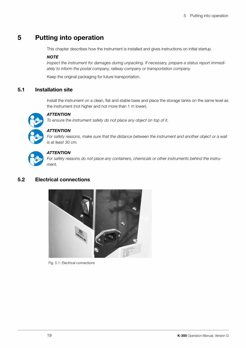
5 .2 Electrical connections
Fig. 5.1: Electrical connections

5 Putting into operation
20 K-350 Operation Manual, Version G
ATTENTIONMake sure that the voltage on the socket corresponds to the voltage given on the type plate of the instrument.
Always connect the instrument to an earthed socket. External connections and extension cables must be provided with an earthed conductor lead (3-pole couplings, cable or plug equipment) as the mains lead has a molded plug, thus avoiding risks due to inadvertent defective wiring.
The instrument cable must be well attainable at all times.
Make sure that no electric sparks form in the instrument or its surroundings as they might damage the instrument.
5 .3 Reagent and water connections
a
b
c
d
e
a H2O inlet (for steam generator) from tankb NaOH input from tankc Cooling water outletd Cooling water inlete Drain to waste
Fig. 5.2: Reagent and water connections
All pumps are self-priming, no overpressure is necessary at the tanks.
5 .3 .1 Cooling water connection
Secure the cooling water hose with a hose clamp on both the instrument and the water connection side. The water pressure should be at a maximum of 4 bar. The built in valve reduces the water flow to 1.2 liters per minute.
The flanged screw coupling for the water connection has a standard screw thread of G ¾”.

5 Putting into operation
21 K-350 Operation Manual, Version G
5 .3 .2 Drainage of cooling water
Place the drain hose for the cooling water directly into the drain. For this purpose, shorten the silicone hose to the optimal length. The drain hose should not show any kinks, sharp bends and/or siphoning effect. Prevent flooding inside and outside the instrument by securing the drain hose.
5 .3 .3 Storage tank connection
To connect the storage tanks, proceed as follows:
• Cut the solaflex tube into pieces of the appropriate length (use an acid resistant tube, if acid is dosed).
• Insert a PTFE suction tube into the solaflex tube.• Push an EPDM sealing ring over the solaflex tube.• Now fasten the tubes to the tank with the red screw cover.• Connect the tubes at the appropriate connections at the instrument side and secure them with the
clamps.
Fig. 5.3: Tank connection
All pumps are self-priming, no overpressure is necessary at the tanks.
ATTENTIONTo ensure proper system functioning, consider the following:
• Use only distilled water for the H2O storage tank to keep the steam generator maintenance-free.• Make sure that the tanks are connected correctly. If the wrong tank (e. g. reagent tank containing
NaOH) is connected to the pump labelled „H2O steam“, the steam generator will be damaged.

6 Operation
22 K-350 Operation Manual, Version G
6 Operation
This chapter gives examples of typical instrument applications and instructions on how to operate the instrument properly and safely.
WARNINGRisk of injury.
• Never operate the instrument when glassware is damaged.
WARNINGSodium hydroxide, acid and lye are used for applications according to Kjeldahl. For this reason, protective goggles must be worn at all times when using this instrument or working in its immediate proximity.
NOTEClose unused connections with plug caps.
6 .1 Addition of chemicals
6 .1 .1 Manual dosage
When pressing “REAGENT” the connected reagent is dosed as long as the switch is pressed.
6 .1 .2 Automatic dosage
The reagent volume dosed before the distillation is started is stored. This volume can be recalled after distillation.The stored volume is dosed by pressing “REAGENT” shortly. After releasing the switch, the volume is dosed automatically.
6 .1 .3 General information
The reagent switch is also active when the instrument is “Ready” or “Busy” (during distillation), so that additional dosage of reagent is possible during distillation.During preheating, reagent addition is not possible.The reagent volume stored before the start of the distillation is defined as the pump operating time.The stored pump operating time (reagent volume) can be recalled after the distillation or after pressing “STOP”.If “STOP” is pressed during the automatic addition of reagent, the default volume is set to 0 mL.

6 Operation
23 K-350 Operation Manual, Version G
6 .2 Setting the distillation time
To set the distillation time, proceed as follows:
• Press “TIME”, the digit for minutes starts to flash.• Press “TIME” again, the digit for seconds starts to flash.• Set the distillation time by pressing “UP” and “DOWN”.• Start the distillation by pressing “START”.Digits stop flashing after a certain time or after starting the distillation.When pressing “UP” and “DOWN”, the time is first counted slowly, then faster.The distillation time can be set in a range of 1 second to 99 minutes 59 seconds.
6 .3 Steam generator status
6 .3 .1 Heating
A constant colon (:) and “HHHH” in the TIME-display as long as “START” is pressed indicates, that the steam generator is heating.A flashing colon (:) and a signal sound for 1 second indicates, that the steam generator is ready.
6 .3 .2 Standby mode (after 30 minutes)
The TIME-display shows (-----).Press “START” to cancel the standby mode.
6 .4 Switching ON/OFF checklist
To switch on and preheat the instrument, proceed as follows:
• Check the filling level of the supply tanks.• Open the main water tap.• Switch on the instrument and wait until the steam generator is ready.• Insert an empty sample tube and an empty receiving vessel.• Close the protective door.• Set the distillation time to 2 minutes (see section “Setting the distillation time”) and the steam to
100 % (see section “Setting the steam power”).• Start the distillation by pressing “START”.
To switch off the instrument, proceed as follows:
• Fill 30 mL distilled water into the sample tube.• Fill 50 mL distilled water into the receiving vessel.• Switch off the instrument.• Close the main water tap.

6 Operation
24 K-350 Operation Manual, Version G
6 .5 Carrying out a Kjeldahl distillation
To carry out a distillation, proceed as follows:
• Switch on the instrument and wait until the steam generator is ready.• Insert the sample tube containing the sample diluted in water. The dilution with water prevents a
too violent reaction when subsequently adding the sodium hydroxide solution. The sample must be diluted in a ratio of approximately 1 part of acid to 2 parts of water.
• Prepare a conical flask or a similar receptacle with a volume of about 250 mL as receiving vessel. Fill boric acid solution 4 % and 2-3 drops of Sher indicator in the receiving vessel. Alternative: Select suitable chemicals for the back titration.
• Add sodium hydroxide solution by pressing “REAGENT“: Recommended alkali concentration: 32 %. Add alkali to the sample in a ratio of about 1 part of acid to 3 parts of sodium hydroxide solution. The volume of the added sodium hydroxide solution is measured on the scale behind the sample tube. The added volume selected must produce a clear shift in color to brown or blue.
• Set the required distillation time.• Start the distillation by pressing “START”.
NOTEAfter distillation or after “STOP“, the last distillation time can be recalled by pressing “START“ or will automatically be recalled when exchanging the sample tube.

7 Maintenance and repairs
25 K-350 Operation Manual, Version G
7 Maintenance
This chapter gives instructions on all maintenance work to be performed in order to keep the instru-ment in good working condition.
WARNINGElectrical hazard:
• Prior to all maintenance work on the instrument switch off the power supply and remove all sources of flammable vapor.
WARNINGAll maintenance and repair work requiring the opening or removal of instrument covers may only be carried out by trained personnel and with the tools provided for this purpose.
WARNINGPotentially hot service door or interior behind the service door during operation (surface temperatures at times exceed 60 °C). Danger of burns.
• Always let the instrument cool down before opening the service door.
ATTENTIONAlways wear personal protective equipment such as protective eye goggles, protective clothing and gloves when maintaining the instrument.
Check the instrument for proper operation after any repair work.
7 .1 Daily maintenance
7 .1 .1 Cleaning the instrument from inside
To ensure proper instrument functioning regular cleaning is vital. Thus the generation of caustic substances within the instrument and the degradation of glassware is avoided. To clean the inside of the instrument, distill 100 mL of distilled water for a period of 2 minutes.
7 .1 .2 Cleaning the housing
Check the housing for defects (switches, plugs) and clean it with a damp cloth.
ATTENTIONNever use solvents as cleaning agents as these might damage the instrument.
• As the housing is made of polyurethane and covered with an acid-resistant coating, any acid drops must be wiped away immediately with a damp cloth.
7 .1 .3 Cleaning the glass parts
The glass parts can be taken out and cleaned with commercially available cleaning agents or in an ultrasonic bath. After the glass parts have been cleaned and fully dried, check each part visually for cracks, scratches and for any parts or sections that might have splintered off. Take out and replace any damaged glass parts.

7 Maintenance and repairs
26 K-350 Operation Manual, Version G
7 .1 .4 Preparing the instrument for a standstill overnight
To prepare the instrument for a longer standstill (e.g. overnight), fill 50 mL distilled water into the receiving vessel and 30 mL of distilled water into the sample tube.
7 .2 Weekly maintenance
7 .2 .1 Cleaning the splash protector and the rubber bung seal
Unmount the splash protector and remove the rubber bung seal.Rinse the splash protector with water to remove sample residues.We recommend to replace the splash protector after approximately 5000 determinations, depending on the kind of application and frequency of maintenance.
To prolong the lifetime of the seal, rinse it with water, especially if working with crystalline products. Afterwards, dry it with a soft cloth, remount it and put the splash protector back in place.
ATTENTIONWhen removing and reinstalling the seal, make sure not to damage it. Always move it perpendicularly to the axis of the glass parts and ensure no damage occurs to the sealing lip.
Never apply grease to the seal and never touch it with sharp objects, otherwise it will get damaged.
7 .3 Monthly maintenance
7 .3 .1 Checking the distillate amount
To check the distillate amount, wait until the steam generator is ready, i.e. the instrument is warmed up. Then run a single sample with an empty tube and an empty receiving vessel with the following parameters:
Table 7-1: Checking the distillate amount
Parameter Setting
Check distillate amount: Distillation and titration
Sample tube: empty
Water: 0 mL
NaOH: 0 mL
Distillation time: 5:00
After the check is finished, measure the distillate amount by means of a measuring flask. With the above parameters it should be about 150 mL.

7 Maintenance and repairs
27 K-350 Operation Manual, Version G
7 .4 Half-yearly maintenance
7 .4 .1 Replacing the NaOH tube
We recommend to replace the NaOH tube every six months. The other tubes need to be replaced as and when required.
7 .5 Yearly maintenance
7 .5 .1 Replacing the rubber bung seal
The seal is subject to wear and tear, thus you should check it regularly. We recommend to replace it once a year.
7 .5 .2 Replacing the NaOH pump
We recommend to replace the NaOH pump once a year.
7 .6 Customer service
Only authorised service personnel are allowed to perform repair work on the instrument. These persons have a comprehensive technical training and knowledge of possible dangers which might arise from the instrument.Addresses of official BUCHI customer service offices are given on the BUCHI website under: www.buchi.com. If malfunctions occur on your instrument or you have technical questions or applica-tion problems, contact one of these offices.
The customer service offers the following:
• Spare part delivery• Repairs• Technical advice

8 Troubleshooting
28 K-350 Operation Manual, Version G
8 Troubleshooting
This chapter helps to resume operation after a minor problem has occurred with the instrument. It lists possible occurrences, their probable cause and suggests how to remedy the problem.The troubleshooting table below lists possible malfunctions and errors of the instrument. The operator is enabled to correct some of those problems or errors by him/herself. For this, appropriate corrective measures are listed in the column “Corrective measure”.The elimination of more complicated malfunctions or errors is usually performed by a BUCHI technical engineer who has access to the official service manuals. In this case, please refer to your local BUCHI customer service agent.
8 .1 Malfunctions and their remedy
Table 8-1: General malfunctions and their remedy
Error number / Error indication Possible cause Corrective measure
E 30 Service door open. Close service door.
E 31 Protective door open. Close protective door.
E 32 Sample tube missing. Insert a sample tube.
E 40 Steam generator overheat. Switch off the instrument immediately and contact the BUCHI customer service.
E 40 - E 47 Electronic problem. Contact the BUCHI customer service.
E 50 - E 56 Steam generator problem. Water feeding problem. Control the water volume in the tank. Control the tube connections.
E 70 - E 72 E 74 - E 76 Signal sound in a 10 seconds interval
Keyboard problem. Switch off the instrument. Contact the BUCHI customer service.
“HHHH” in the TIME display Steam generator is heating, not ready for distillation.
Heating takes approx. 3 minutes. A flashing colon (:) indicates that the steam generator is ready.

9 Shutdown, storage, transport and disposal
29 K-350 Operation Manual, Version G
9 Shutdown, storage, transport and disposal
This chapter instructs how to shut down the instrument, how to pack it for storage or transport, and specifies the storage and shipping conditions.
9 .1 Preparing the instrument for transport
Take out the power cord and remove all water/reagent tubing. Rinse the sodium hydroxide solution tube with distilled water. Clean the instrument thoroughly, so that all chemical residues are removed completely.
To empty the steam generator, proceed as follows:
• Turn off the instrument and disconnect the power cord.
WARNINGThe steam generator gets very hot during operation. Danger of being burned.
• Always let the steam generator cool down for at least 30 minutes after having switched it off before handling it.
• Open the service door.• Attach an appropriate silicone tube to the drain cock.• Place a receiving vessel with a volume of 500 mL below the end of the tube.• Slowly open the stop-cock with a screw driver and empty the steam generator completely.
9 .2 Storage and transport
Store and transport the instrument in its original packaging.
9 .3 Disposal
To dispose of the instrument in an environmentally friendly manner, a list of materials is given in chapter 3. This helps to ensure that the components are separated and recycled correctly.Please follow valid regional and local laws concerning disposal.

10 Spare parts
30 K-350 Operation Manual, Version G
10 Spare parts
This chapter lists spare parts, accessories, and options including their ordering information.Order the spare parts from BUCHI. Always state the product designation and the part number when ordering spare parts.Use only genuine BUCHI consumables and genuine spare parts for maintenance and repair to assure good system performance and reliability. Any modifications to the spare parts used are only allowed with the prior written permission of the manufacturer.
10 .1 Spare parts K-350
2 3
45 6
7
89
1
Table 10-1: Spare parts K-350
Product Order number
a Set of clamps Ø 7.6 / Ø 11.9 / Ø 9.6 / Ø 10.7 / Ø 12.8 (5 pieces each)
43586
b SVL 22 screw cap 03577
c SVL 22 sealing 02073
d Outlet tube for distillate, PTFE 43569
e Set of hose connectors, bent EPDM sealing (4 pieces)
43129
f Set of hose connectors, straight, FPM sealing (4 pieces)
40296
g Set of sealings, FPM (10 pieces) 40040
h Gasket, complete (splash protector) 43068
i Set of connectors cooling water outlet (1 piece of each)
43538
11
12
10
j Splash protector, glass
Splash protector, polypropylene
43332
43590
k Condenser 43320
l Check valve, complete 43356
13
m Set of accessories for splash protector K-350 and K-355
43585

10 Spare parts
31 K-350 Operation Manual, Version G
14
Table 10-1: Spare parts K-350 (cont.)
Product Order number
n Drip tray 43302
Caps for 20 l tanks, large (2 pieces) 43478
10 .2 Hosing connection scheme
2
3
4
5
6
7
8
9
10
11
1
a Inletb NaOH tankc H2O tankd Valve cooling water ine Pump NaOHf Pump H2O steam generator
g Coolerh Receiving vesseli Splash protectorj Valve steamk Output
Fig. 10.1: Hosing connection scheme

10 Spare parts
32 K-350 Operation Manual, Version G
Table 10-2: Tubes and components Distillation Unit K-350
Position Order number Pcs Description
1 - 2 43555 1 Solaflex tube Ø 10/5, L = 3500
3 43153 1 Unisil Ø 6×2, L = 640
4 43151 1 Unisil Ø 6×2, L = 370
5 43154 1 Unisil Ø 6×2, L = 920
6 43027 1 Tersil tube Ø 12/6, L = 175
7 43147 1 Tersil tube Ø 12/6, L = 360
8 43145 1 Tersil tube Ø 12/6, L = 65
9 43029 1 EPDM 6.35/1.58, L = 530
11 43940 1 Silicone tube Ø 9/6, L = 1500
12 37780 1 Cooling water tube complete, L = 1500
13 43940 1 Silicone tube Ø 9/6, L = 1500
101 43139 3 Connectors GL-14, bent, EPDM
102 27738 2 Hose clamps Ø 9.6, black
103 43202 5 Hose clamps Ø 10.7, green
104 43841 5 Hose clamps Ø 11.9, black
105 43519 1 Reduction piece
106 43207 1 Tube spout
107 43204 1 T-piece PVDF
108 43560 1 Tube holder
109 43297 5 Hose clamps Ø 12.8, white
110 43534 1 Screw-on spout D6, G1/8”
111 43386 1 Screw-in spout D6, G1/8”
112 40297 1 Connector, bent, green

11 Declarations and requirements
33 K-350 Operation Manual, Version G
11 Declarations and requirements
11 .1 FCC requirements (for USA and Canada)
English:
This equipment has been tested and found to comply with the limits for a Class A digital device, pursuant to both Part 15 of the FCC Rules and the radio interference regulations of the Canadian Department of Communications. These limits are designed to provide reasonable protection against harmful interference when the equipment is operated in a commercial environment.This equipment generates, uses and can radiate radio frequency energy and, if not installed and used in accordance with the instruction manual, may cause harmful interference to radio communications. Operation of this equipment in a residential area is likely to cause harmful interference in which case the user will be required to correct the interference at his own expense.
Français:
Cet appareil a été testé et s’est avéré conforme aux limites prévues pour les appareils numériques de classe A et à la partie 15 des réglementations FCC ainsi qu’à la réglementation des interférences radio du Canadian Department of Communications. Ces limites sont destinées à fournir une protec-tion adéquate contre les interférences néfastes lorsque l’appareil est utilisé dans un environnement commercial.Cet appareil génère, utilise et peut irradier une énergie à fréquence radioélectrique, il est en outre susceptible d’engendrer des interférences avec les communications radio, s’il n’est pas installé et utilisé conformément aux instructions du mode d’emploi. L’utilisation de cet appareil dans les zones résidentielles peut causer des interférences néfastes, auquel cas l’exploitant sera amené à prendre les
dispositions utiles pour palier aux interférences à ses propres frais.


Quality in your hands
BUCHI Affiliates:
We are represented by more than 100 distribution partners worldwide. Find your local representative at: www.buchi.com
BUCHI Support Centers:
Europe
Switzerland/Austria
BÜCHI Labortechnik AGCH – 9230 Flawil T +41 71 394 63 63F +41 71 394 65 [email protected]
Benelux
BÜCHI Labortechnik GmbHBranch Offi ce Benelux NL – 3342 GT Hendrik-Ido-Ambacht T +31 78 684 94 29F +31 78 684 94 30 [email protected]
France
BUCHI SarlFR – 94656 Rungis CedexT +33 1 56 70 62 50F +33 1 46 86 00 [email protected]
Germany
BÜCHI Labortechnik GmbHDE – 45127 EssenT +800 414 0 414 0 (Toll Free)T +49 201 747 49 0F +49 201 747 49 20 [email protected]
Italy
BUCHI Italia s.r.l.IT – 20010 Cornaredo (MI)T +39 02 824 50 11F +39 02 575 12 [email protected]
Russia
BUCHI Russia/CISRussia 127287 MoscowT +7 495 36 36 495F +7 495 98 10 [email protected]
United Kingdom
BUCHI UK Ltd.GB – Oldham OL9 9QLT +44 161 633 1000F +44 161 633 [email protected]
Germany
BÜCHI NIR-OnlineDE – 69190 Walldorf T +49 6227 73 26 60F +49 6227 73 26 [email protected]
China
BUCHI ChinaCN – 200052 ShanghaiT +86 21 6280 3366F +86 21 5230 [email protected]
India
BUCHI India Private Ltd.IN – Mumbai 400 055 T +91 22 667 75400F +91 22 667 [email protected] www.buchi.in
Indonesia
PT. BUCHI IndonesiaID – Tangerang 15321T +62 21 537 62 16F +62 21 537 62 [email protected]
Japan
Nihon BUCHI K.K. JP – Tokyo 110-0008 T +81 3 3821 4777F +81 3 3821 [email protected]
Korea
BUCHI Korea Inc.KR – Seoul 153-782T +82 2 6718 7500F +82 2 6718 [email protected]
Malaysia
BUCHI Malaysia Sdn. Bhd. MY – 47301 Petaling Jaya, SelangorT +60 3 7832 0310F +60 3 7832 [email protected]
Singapore
BUCHI Singapore Pte. Ltd. SG – Singapore 609919T +65 6565 1175F +65 6566 [email protected]
Thailand
BUCHI (Thailand) Ltd. TH – Bangkok 10600T +66 2 862 08 51F +66 2 862 08 [email protected]
Asia
America
Brazil
BUCHI Brasil Ltda.BR – Valinhos SP 13271-200T +55 19 3849 1201 F +55 19 3849 [email protected]
USA/Canada
BUCHI CorporationUS – New Castle, DE 19720T +1 877 692 8244 (Toll Free)T +1 302 652 3000F +1 302 652 [email protected]
South East Asia
BUCHI (Thailand) Ltd.TH-Bangkok 10600T +66 2 862 08 51F +66 2 862 08 [email protected]
Middle East
BÜCHI Labortechnik AGUAE – Dubai T +971 4 313 2860F +971 4 313 [email protected]
Latin America
BUCHI Latinoamérica Ltda.BR – Valinhos SP 13271-200T +55 19 3849 1201F +55 19 3849 [email protected]