
jvc_ca_hxd7_sm_2
45
SERVICE MANUAL COPYRIGHT © 2005 Victor Company of Japan, Limited No.MB455 2005/8 COMPACT COMPONENT SYSTEM MB455 2005 8 HX-D7 Lead free solder used in the board (material : Sn-Ag-Cu, melting point : 219 Centigrade) TABLE OF CONTENTS 1 PRECAUTION. . . . . . . . . . . . . . . . . . . . . . . . . . . . . . . . . . . . . . . . . . . . . . . . . . . . . . . . . . . . . . . . . . . . . . . . . 1-3 2 SPECIFIC SERVICE INSTRUCTIONS . . . . . . . . . . . . . . . . . . . . . . . . . . . . . . . . . . . . . . . . . . . . . . . . . . . . . . 1-4 3 DISASSEMBLY . . . . . . . . . . . . . . . . . . . . . . . . . . . . . . . . . . . . . . . . . . . . . . . . . . . . . . . . . . . . . . . . . . . . . . . 1-5 4 ADJUSTMENT . . . . . . . . . . . . . . . . . . . . . . . . . . . . . . . . . . . . . . . . . . . . . . . . . . . . . . . . . . . . . . . . . . . . . . . 1-17 5 TROUBLESHOOTING . . . . . . . . . . . . . . . . . . . . . . . . . . . . . . . . . . . . . . . . . . . . . . . . . . . . . . . . . . . . . . . . . 1-17 CA-HXD7 SP-HXD7 SP-HXD7 Area suffix UJ ---------------------- U.S.Military
Transcript of jvc_ca_hxd7_sm_2

SERVICE MANUAL
COPYRIGHT © 2005 Victor Company of Japan, Limited No.MB4552005/8
COMPACT COMPONENT SYSTEMMB45520058
HX-D7
Lead free solder used in the board (material : Sn-Ag-Cu, melting point : 219 Centigrade)
TABLE OF CONTENTS1 PRECAUTION. . . . . . . . . . . . . . . . . . . . . . . . . . . . . . . . . . . . . . . . . . . . . . . . . . . . . . . . . . . . . . . . . . . . . . . . . 1-32 SPECIFIC SERVICE INSTRUCTIONS . . . . . . . . . . . . . . . . . . . . . . . . . . . . . . . . . . . . . . . . . . . . . . . . . . . . . . 1-43 DISASSEMBLY . . . . . . . . . . . . . . . . . . . . . . . . . . . . . . . . . . . . . . . . . . . . . . . . . . . . . . . . . . . . . . . . . . . . . . . 1-54 ADJUSTMENT . . . . . . . . . . . . . . . . . . . . . . . . . . . . . . . . . . . . . . . . . . . . . . . . . . . . . . . . . . . . . . . . . . . . . . . 1-175 TROUBLESHOOTING . . . . . . . . . . . . . . . . . . . . . . . . . . . . . . . . . . . . . . . . . . . . . . . . . . . . . . . . . . . . . . . . . 1-17
CA-HXD7 SP-HXD7SP-HXD7
Area suffix
UJ ---------------------- U.S.Military
1-2 (No.MB455)
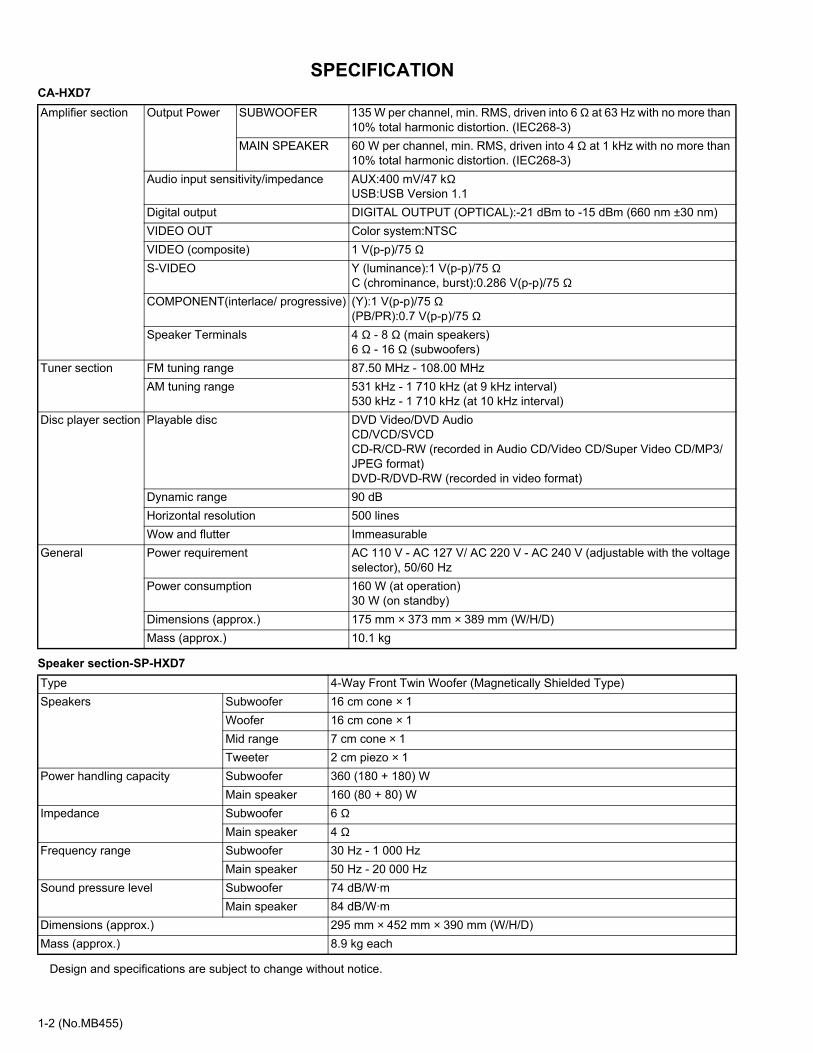
SPECIFICATIONCA-HXD7
Speaker section-SP-HXD7
Design and specifications are subject to change without notice.
Amplifier section Output Power SUBWOOFER 135 W per channel, min. RMS, driven into 6 Ω at 63 Hz with no more than 10% total harmonic distortion. (IEC268-3)
MAIN SPEAKER 60 W per channel, min. RMS, driven into 4 Ω at 1 kHz with no more than 10% total harmonic distortion. (IEC268-3)
Audio input sensitivity/impedance AUX:400 mV/47 kΩUSB:USB Version 1.1
Digital output DIGITAL OUTPUT (OPTICAL):-21 dBm to -15 dBm (660 nm ±30 nm)VIDEO OUT Color system:NTSCVIDEO (composite) 1 V(p-p)/75 ΩS-VIDEO Y (luminance):1 V(p-p)/75 Ω
C (chrominance, burst):0.286 V(p-p)/75 ΩCOMPONENT(interlace/ progressive) (Y):1 V(p-p)/75 Ω
(PB/PR):0.7 V(p-p)/75 ΩSpeaker Terminals 4 Ω - 8 Ω (main speakers)
6 Ω - 16 Ω (subwoofers)Tuner section FM tuning range 87.50 MHz - 108.00 MHz
AM tuning range 531 kHz - 1 710 kHz (at 9 kHz interval)530 kHz - 1 710 kHz (at 10 kHz interval)
Disc player section Playable disc DVD Video/DVD AudioCD/VCD/SVCDCD-R/CD-RW (recorded in Audio CD/Video CD/Super Video CD/MP3/JPEG format)DVD-R/DVD-RW (recorded in video format)
Dynamic range 90 dBHorizontal resolution 500 linesWow and flutter Immeasurable
General Power requirement AC 110 V - AC 127 V/ AC 220 V - AC 240 V (adjustable with the voltage selector), 50/60 Hz
Power consumption 160 W (at operation)30 W (on standby)
Dimensions (approx.) 175 mm × 373 mm × 389 mm (W/H/D)Mass (approx.) 10.1 kg
Type 4-Way Front Twin Woofer (Magnetically Shielded Type)Speakers Subwoofer 16 cm cone × 1
Woofer 16 cm cone × 1Mid range 7 cm cone × 1Tweeter 2 cm piezo × 1
Power handling capacity Subwoofer 360 (180 + 180) WMain speaker 160 (80 + 80) W
Impedance Subwoofer 6 ΩMain speaker 4 Ω
Frequency range Subwoofer 30 Hz - 1 000 HzMain speaker 50 Hz - 20 000 Hz
Sound pressure level Subwoofer 74 dB/W·mMain speaker 84 dB/W·m
Dimensions (approx.) 295 mm × 452 mm × 390 mm (W/H/D)Mass (approx.) 8.9 kg each

(No.MB455)1-3
SECTION 1PRECAUTION
1.1 Safety Precautions(1) This design of this product contains special hardware and
many circuits and components specially for safety purpos-es. For continued protection, no changes should be madeto the original design unless authorized in writing by themanufacturer. Replacement parts must be identical tothose used in the original circuits. Services should be per-formed by qualified personnel only.
(2) Alterations of the design or circuitry of the product shouldnot be made. Any design alterations of the product shouldnot be made. Any design alterations or additions will voidthe manufacturers warranty and will further relieve themanufacture of responsibility for personal injury or propertydamage resulting therefrom.
(3) Many electrical and mechanical parts in the products havespecial safety-related characteristics. These characteris-tics are often not evident from visual inspection nor can theprotection afforded by them necessarily be obtained by us-ing replacement components rated for higher voltage, watt-age, etc. Replacement parts which have these specialsafety characteristics are identified in the Parts List of Ser-vice Manual. Electrical components having such featuresare identified by shading on the schematics and by ( ) onthe Parts List in the Service Manual. The use of a substitutereplacement which does not have the same safety charac-teristics as the recommended replacement parts shown inthe Parts List of Service Manual may create shock, fire, orother hazards.
(4) The leads in the products are routed and dressed with ties,clamps, tubings, barriers and the like to be separated fromlive parts, high temperature parts, moving parts and/orsharp edges for the prevention of electric shock and firehazard. When service is required, the original lead routingand dress should be observed, and it should be confirmedthat they have been returned to normal, after reassem-bling.
(5) Leakage shock hazard testingAfter reassembling the product, always perform an isola-tion check on the exposed metal parts of the product (an-tenna terminals, knobs, metal cabinet, screw heads,headphone jack, control shafts, etc.) to be sure the productis safe to operate without danger of electrical shock.Do notuse a line isolation transformer during this check.• Plug the AC line cord directly into the AC outlet. Using a
"Leakage Current Tester", measure the leakage currentfrom each exposed metal parts of the cabinet, particular-ly any exposed metal part having a return path to thechassis, to a known good earth ground. Any leakage cur-rent must not exceed 0.5mA AC (r.m.s.).
• Alternate check methodPlug the AC line cord directly into the AC outlet. Use anAC voltmeter having, 1,000Ω per volt or more sensitivityin the following manner. Connect a 1,500Ω 10W resistorparalleled by a 0.15µF AC-type capacitor between an ex-posed metal part and a known good earth ground.Measure the AC voltage across the resistor with the AC
voltmeter. Move the resistor connection to each exposed metalpart, particularly any exposed metal part having a returnpath to the chassis, and measure the AC voltage acrossthe resistor. Now, reverse the plug in the AC outlet andrepeat each measurement. Voltage measured any mustnot exceed 0.75 V AC (r.m.s.). This corresponds to 0.5mA AC (r.m.s.).
1.2 Warning(1) This equipment has been designed and manufactured to
meet international safety standards.(2) It is the legal responsibility of the repairer to ensure that
these safety standards are maintained.(3) Repairs must be made in accordance with the relevant
safety standards.(4) It is essential that safety critical components are replaced
by approved parts.(5) If mains voltage selector is provided, check setting for local
voltage.
1.3 CautionBurrs formed during molding may be left over on some partsof the chassis. Therefore, pay attention to such burrs in the case of pre-forming repair of this system.
1.4 Critical parts for safetyIn regard with component parts appearing on the silk-screenprinted side (parts side) of the PWB diagrams, the parts that areprinted over with black such as the resistor ( ), diode ( )and ICP ( ) or identified by the " " mark nearby are criticalfor safety. When replacing them, be sure to use the parts of thesame type and rating as specified by the manufacturer. (This regulation dose not Except the J and C version)
Good earth ground
Place this probe on each exposedmetal part.
AC VOLTMETER(Having 1000 ohms/volts,or more sensitivity)
1500 10W
0.15 F AC TYPE

1-4 (No.MB455)
SECTION 2SPECIFIC SERVICE INSTRUCTIONS
This service manual does not describe SPECIFIC SERVICE INSTRUCTIONS.

(No.MB455)1-5
SECTION 3DISASSEMBLY
3.1 Main body section3.1.1 Removing the metal cover
(See Figs.1 to 3)(1) From the back side of the main body, remove the five
screws A attaching the metal cover. (See Fig.1.)(2) From the both sides of the main body, remove the four
screws A attaching the metal cover. (See Figs.2 and 3.)(3) Remove the metal cover from the main body while lifting
the rear section of the metal cover in the direction of the ar-row. (See Figs.2 and 3.)
Fig.1
Fig.2
Fig.3
Metal cover
A
A
A
AA
Metal cover
A
A
Metal cover A
A

1-6 (No.MB455)
3.1.2 Removing the tuner (See Figs.4 and 5)
• Remove the metal cover.(1) From the left side of the main body, disconnect the card
wire from the connector on the tuner. (See Fig.4.)(2) From the back side of the main body, remove the two
screws B attaching the tuner to the rear panel. (See Fig.5.)
Fig.4
Fig.5
TunerConnector
Rear panel
B
Tuner
(No.MB455)1-7
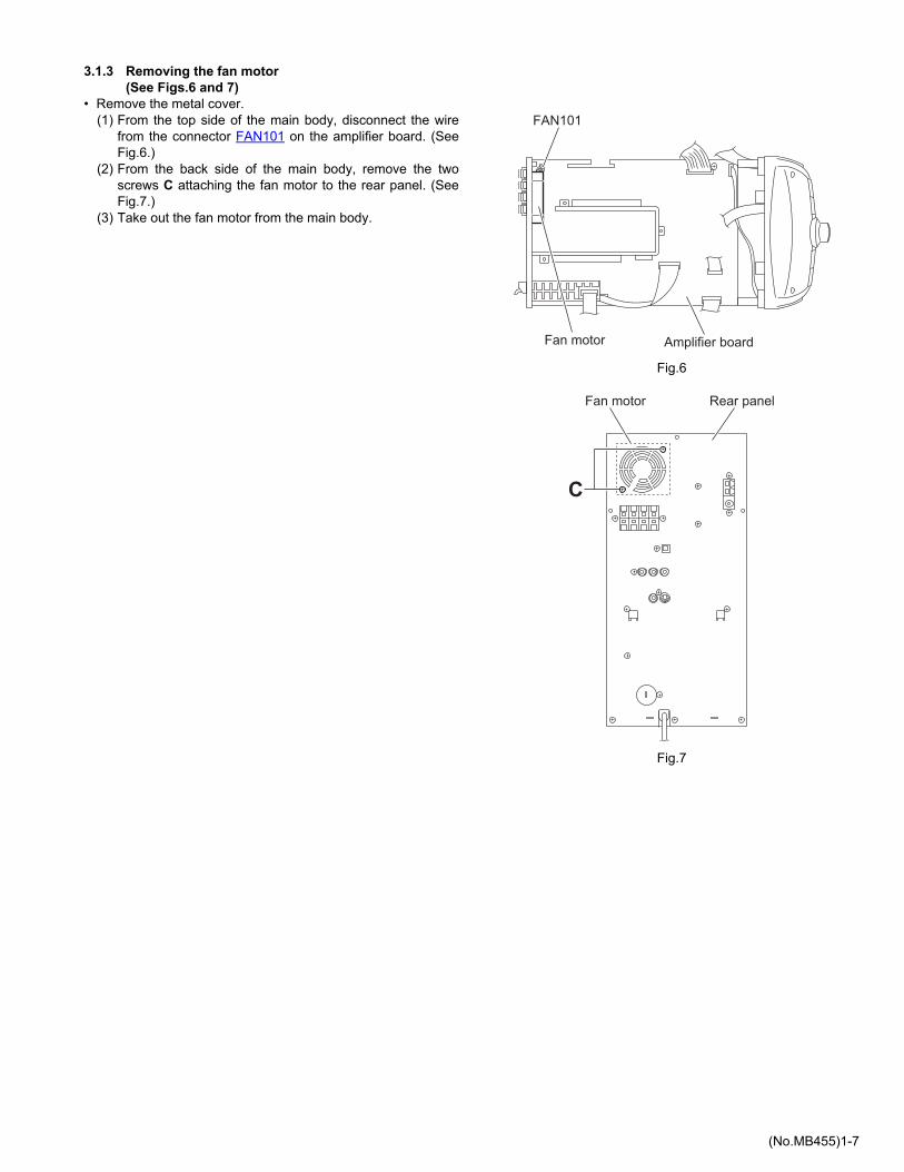
3.1.3 Removing the fan motor (See Figs.6 and 7)
• Remove the metal cover.(1) From the top side of the main body, disconnect the wire
from the connector FAN101 on the amplifier board. (SeeFig.6.)
(2) From the back side of the main body, remove the twoscrews C attaching the fan motor to the rear panel. (SeeFig.7.)
(3) Take out the fan motor from the main body.
Fig.6
Fig.7
Amplifier board
FAN101
Fan motor
Fan motor
C
Rear panel

1-8 (No.MB455)
3.1.4 Removing the rear panel (See Fig.8)
• Remove the metal cover.(1) From the back side of the main body, remove the fifteen
screws D and screw E attaching the rear panel.(2) Remove the sections a toward this side and remove the
rear panel from the sections b.
Fig.8
3.1.5 Removing the video board (See Fig.9)
• Remove the metal cover and rear panel.From the back side of the main body, disconnect the card wirefrom the connector CN101 on the video board.
Fig.9
Rear panel
D D
D
a a
b b
D
E
CN101
Video board
(No.MB455)1-9
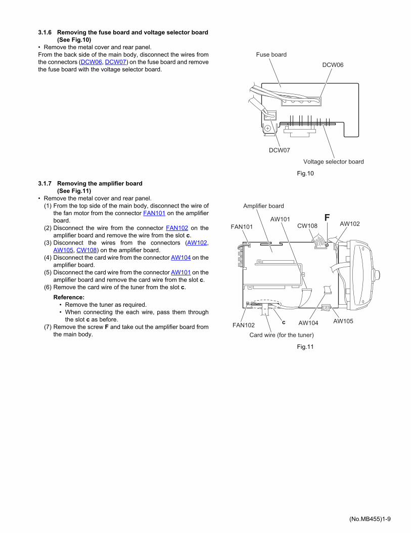
3.1.6 Removing the fuse board and voltage selector board (See Fig.10)
• Remove the metal cover and rear panel.From the back side of the main body, disconnect the wires fromthe connectors (DCW06, DCW07) on the fuse board and removethe fuse board with the voltage selector board.
Fig.10
3.1.7 Removing the amplifier board (See Fig.11)
• Remove the metal cover and rear panel.(1) From the top side of the main body, disconnect the wire of
the fan motor from the connector FAN101 on the amplifierboard.
(2) Disconnect the wire from the connector FAN102 on theamplifier board and remove the wire from the slot c.
(3) Disconnect the wires from the connectors (AW102,AW105, CW108) on the amplifier board.
(4) Disconnect the card wire from the connector AW104 on theamplifier board.
(5) Disconnect the card wire from the connector AW101 on theamplifier board and remove the card wire from the slot c.
(6) Remove the card wire of the tuner from the slot c.
Reference:• Remove the tuner as required.• When connecting the each wire, pass them through
the slot c as before.(7) Remove the screw F and take out the amplifier board from
the main body.
Fig.11
Fuse board
Voltage selector board
DCW06
DCW07
Amplifier board
FAN101
Card wire (for the tuner)
AW101CW108 AW102
F
cFAN102 AW104 AW105

1-10 (No.MB455)
3.1.8 Removing the power amplifier ICs (See Figs.12 to 14)
• Remove the metal cover, rear panel and amplifier board.(1) From the forward side of the amplifier board, remove the
four screws G and screw H attaching the power amplifierICs to the heat sink. (See Figs.12 and 13.)
(2) From the reverse side of the amplifier board, remove thethree screws J attaching the heat sink. (See Fig.14.)
(3) Remove the soldered sections (d, e, f) and remove thepower amplifier ICs from the forward side of the amplifierboard. (See Fig.14.)
Fig.12
Fig.13
Fig.14
Amplifier board
G
Heat sink
Power amplifier IC (AIC01)
Amplifier board
G H
Heat sinkPower amplifier IC (PIC02)
Power amplifier IC (AIC02)
Amplifier board
J
d
f
e

(No.MB455)1-11
3.1.9 Removing the 5DVD changer mechanism assembly (See Figs.15 to 19)
• Remove the metal cover, rear panel, video board and amplifierboard.(1) From the right side of the main body, remove the card wire
from the sections g of the shield. (See Fig.15.)(2) From the left side of the main body, remove the wire from
the sections h of the shield. (See Fig.16.)(3) From the both sides of the main body, remove the four
screws K and remove the shield from the main body. (SeeFigs.15 and 16.)
(4) Disconnect the wires from the connectors (DCW02,DCW04, DCW05) on the DVD power board. (See Fig.17.)
(5) From the both sides of the main body, remove the fourscrews M and remove the 5DVD changer mechanism as-sembly from the main body in the direction of the arrow.(See Figs.17 and 18.)
(6) Disconnect the card wire from the connector CW104 on theforward side of the main board. (See Fig.18.)
(7) From the top side of the 5DVD changer mechanism as-sembly, remove the four screws N and remove the base 1and base 2. (See Fig.19.)
(8) From the bottom side of the 5DVD changer mechanism as-sembly, disconnect the card wire from the connectorCN701 on the DVD servo control board. (See Fig.19.)
Reference:When removing the tray panels, release the claws j of the traypanel and remove the five tray panels from the 5DVD changermechanism assembly. (See Fig.19.)
Note:When releasing the claws j, take care not to break them. (SeeFig.19.)
Fig.15
Fig.16
Fig.17
Shield
g
K
Shield
K
h
5DVD changer mechanism assembly
M
DCW02
DCW04
DVD power board
DCW05

1-12 (No.MB455)
Fig.18
Fig.19
5DVD changer mechanism assembly
M
CW104Main board
Base 2Base 1
NN
NN
5DVD changer mechanism assembly
Tray panels
j
CN701
DVD servocontrol board
j
(No.MB455)1-13
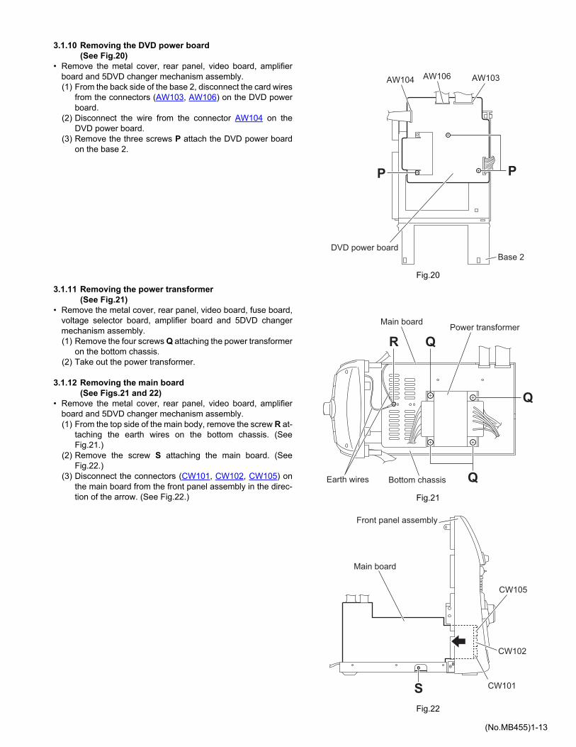
3.1.10 Removing the DVD power board (See Fig.20)
• Remove the metal cover, rear panel, video board, amplifierboard and 5DVD changer mechanism assembly.(1) From the back side of the base 2, disconnect the card wires
from the connectors (AW103, AW106) on the DVD powerboard.
(2) Disconnect the wire from the connector AW104 on theDVD power board.
(3) Remove the three screws P attach the DVD power boardon the base 2.
Fig.20
3.1.11 Removing the power transformer (See Fig.21)
• Remove the metal cover, rear panel, video board, fuse board,voltage selector board, amplifier board and 5DVD changermechanism assembly.(1) Remove the four screws Q attaching the power transformer
on the bottom chassis.(2) Take out the power transformer.
3.1.12 Removing the main board (See Figs.21 and 22)
• Remove the metal cover, rear panel, video board, amplifierboard and 5DVD changer mechanism assembly.(1) From the top side of the main body, remove the screw R at-
taching the earth wires on the bottom chassis. (SeeFig.21.)
(2) Remove the screw S attaching the main board. (SeeFig.22.)
(3) Disconnect the connectors (CW101, CW102, CW105) onthe main board from the front panel assembly in the direc-tion of the arrow. (See Fig.22.) Fig.21
Fig.22
Base 2
P
AW103AW106AW104
DVD power board
P
Earth wires Bottom chassis
Main boardPower transformer
R
Q
Q
Q
Main board
CW101
CW102
CW105
Front panel assembly
S

1-14 (No.MB455)
3.1.13 Removing the front panel assembly (See Figs.21, 23 to 25)
• Remove the metal cover, rear panel, video board, amplifierboard and 5DVD changer mechanism assembly.(1) From the top side of the main body, remove the screw R at-
taching the earth wires on the bottom chassis. (SeeFig.21.)
(2) From the both sides of the main body, remove the twoscrews T attaching the front panel assembly. (See Figs.23and 24.)
(3) From the both and bottom sides of the main body, releasethe joints (k, m) and remove the front panel assembly fromthe main body in the direction of the arrow. (See Figs.23 to25.)
Fig.23
Fig.24
Fig.25
Front panel assembly
k T
Front panel assembly
kT
Front panel assembly
m

(No.MB455)1-15
3.1.14 Removing the FL board (See Fig.26)
• Remove the metal cover, rear panel, video board, amplifierboard, 5DVD changer mechanism assembly and front panelassembly.(1) From the inside of the front panel assembly, remove the
four screws U attaching the FL board.(2) Take out the FL board from the front panel assembly and
disconnect the card wire from the connector FW102 on theforward side of the FL board.
Fig.26
U
U
FW102 FL board
Front panel assembly

1-16 (No.MB455)
3.1.15 Removing the switch board (See Figs.27 and 28)
• Remove the metal cover, rear panel, video board, amplifierboard, 5DVD changer mechanism assembly, front panel as-sembly and FL board.(1) From the inside of the front panel assembly, remove the
spacer on the switch board.(2) Remove the five screws U attaching the switch board. (See
Fig.27.)(3) Take out the switch board while lifting it from the front panel
assembly little by little.
Reference:The preset knob is removed from the front side simulta-neously. (See Fig.28.)
(4) Take out the switch board from the front panel assemblyand disconnect the card wire from the connector FW201 onthe forward side of the switch board. (See Fig.27.)
3.1.16 Removing the volume board (See Figs.28 and 29)
• Remove the metal cover, rear panel, video board, amplifierboard, 5DVD changer mechanism assembly and front panelassembly.(1) From the front side of the front panel assembly, pull out the
volume knob in the direction of the arrow. (See Fig.28.)(2) From the inside of the front panel assembly, disconnect the
card wire from the connector FW301 on the volume board.(See Fig.29.)
(3) Remove the seven screws U attaching the volume board.(See Fig.29.)
(4) Take out the volume board from the front panel assemblyand disconnect the wires from the connectors (FW307,FW308) on the forward side of the volume board. (SeeFig.29.)
3.1.17 Removing the jack board (See Fig.29)
• Remove the metal cover, rear panel, video board, amplifierboard, 5DVD changer mechanism assembly, front panel as-sembly and volume board.
Remove the three screws U and take out the jack board from thefront panel assembly.
Fig.27
Fig.28
Fig.29
U
FW201
Switch boardU
Spacer
Front panel assembly
Preset knob
Volume knob
FW301
Volume board
U
Jack board
U
UU
FW307
FW308
UU

(No.MB455)1-17
SECTION 4ADJUSTMENT
This service manual does not describe ADJUSTMENT.
SECTION 5TROUBLESHOOTING
This service manual does not describe TROUBLESHOOTING.

(No.MB455)
AV & MULTIMEDIA COMPANY AUDIO/VIDEO SYSTEMS CATEGORY 10-1,1chome,Ohwatari-machi,Maebashi-city,371-8543,JapanVictor Company of Japan, Limited
VPTPrinted in Japan

SCHEMATIC DIAGRAMS
HX-D7
Contents Block diagramStandard schematic diagramsPrinted circuit boards
2-12-22-7 to 11
CD-ROM No.SML200508
COMPACT COMPONENT SYSTEM
No.MB455SCH2005/8
COPYRIGHT 2005 Victor Company of Japan, Limited.
Lead free solder used in the board (material : Sn-Ag-Cu, melting point : 219 Centigrade)
CA-HXD7 SP-HXD7SP-HXD7
Area suffix
UJ ---------------------- U.S.Military

In regard with component parts appearing on the silk-screen printed side (parts side) of the PWB diagrams, the
parts that are printed over with black such as the resistor ( ), diode ( ) and ICP ( ) or identified by the " "
mark nearby are critical for safety.

2-1
Block diagram
Voltage
selector
5.6
V
VIDEO DRIVER
MM1623XFBE
HP AMP
4556
AC INPUT
SUB WOOFER
MAINL.P.F
L.P.F
L.P.F
L.P.F
AMP IC
STK428-610
FRONT CH
AMP IC
STK428-640
SUB-WOOFER CH
L.P.F
324
H.P.F
4558BUFFER
4558
RHYTHM AX
JCV8011
FUNCTION
TDA7442D
INPUT1
INPUT2
INPUT3
INPUT4
TUNER
CD/MP3DVD
AUX
VIDEO
HEADPHONE
USB DIGITAL SIG.USB AUDIO IC
CM102
US
B O
N
DA
TA
/CL
K C
OM
MA
ND
REM
OCON
KEY COMAND u-COM
V.F.DISPLAY
FRONT PCB ASS'Y
5V 5V REG. IC78L05
P.SENS
POWER ON
SIG
NA
L 1
2V
DV
D 8
.6V
MO
TO
R 1
2V
L4959
-VP
VFD
PE212
PE201
PE202
PE203PE204
PE205
PD211-2141N5392
AC
VFD
PD202
PBD021N5402
PBD011N5402

2-2
Main sectionStandard schematic diagrams

2-3
Parts are safety assurance parts.
When replacing those parts make
sure to use the specified one.
Amp section

2-4
FL & Key control section

2-5
Parts are safety assurance parts.
When replacing those parts make
sure to use the specified one.
DVD primary section

2-6
Vide section

2-7
Printed circut boards
Main board Lead free solder used in the board (material : Sn-Ag-Cu, melting point : 219 Centigrade)
(Forward sde)

2-8
Main board Lead free solder used in the board (material : Sn-Ag-Cu, melting point : 219 Centigrade)
(Reverse sde)

2-9
Amp board Lead free solder used in the board (material : Sn-Ag-Cu, melting point : 219 Centigrade)
(Forward side) (Reverse side)

2-10
Front board Lead free solder used in the board (material : Sn-Ag-Cu, melting point : 219 Centigrade)
(Forward side) (Reverse side)

2-11
Power board Lead free solder used in the board (material : Sn-Ag-Cu, melting point : 219 Centigrade)

Victor Company of Japan, Limited
(No.MB455SCH)Printed in Japan
VPT
AV & MULTIMEDIA COMPANY AUDIO/VIDEO SYSTEMS CATEGORY 10-1,1chome,Ohwatari-machi,Maebashi-city,371-8543,Japan

PARTS LIST
* All printed circuit boards and its assemblies are not available as service parts.
- Contents -
Exploded view of general assembly and parts list (Block No.M1)
Electrical parts list (Block No.01~06)
Packing materials and accessories parts list (Block No.M3)
[ HX-D7 ]
3- 23- 53-12
Area suffix
UJ --------------------- U.S.Military
3-1MB455
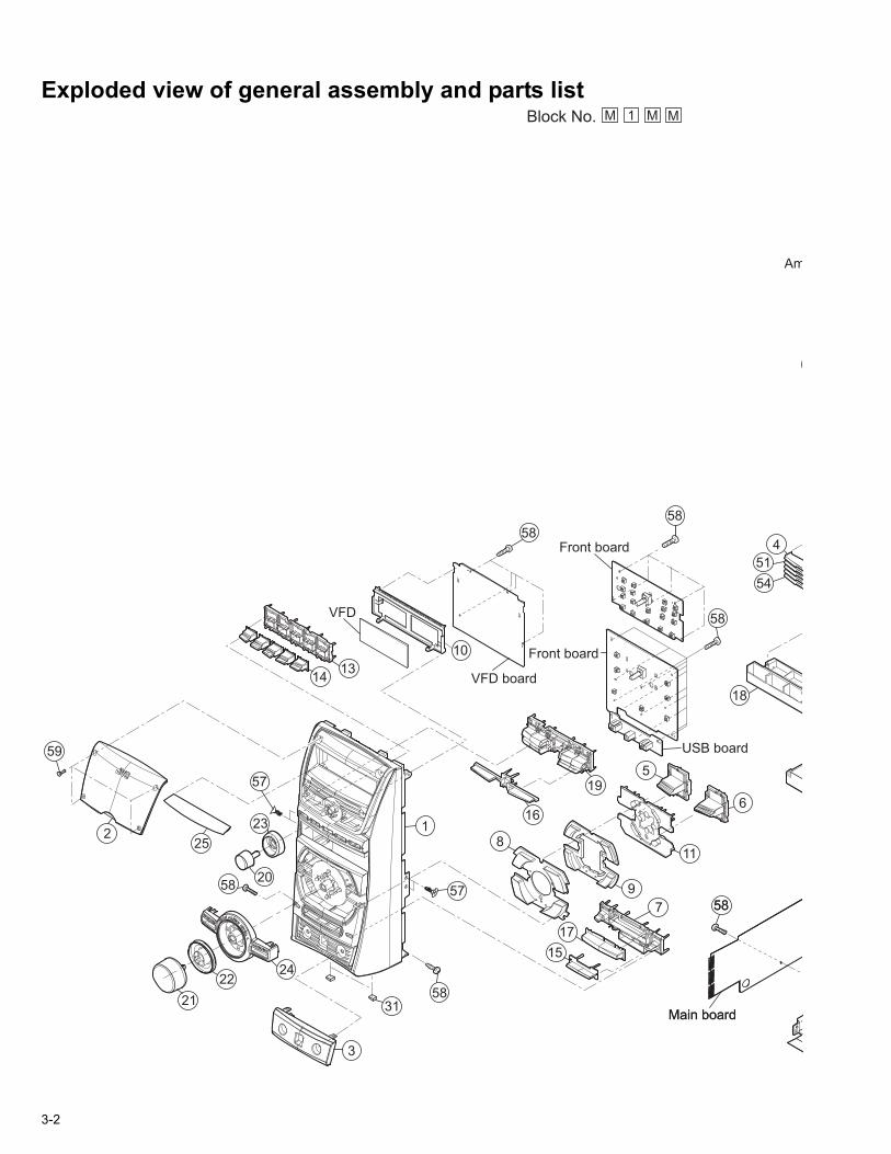
Exploded view of general assembly and parts list
14
59
21
2224
20
252
57
23
3
5831
57
1
15
17
58587
16
195
6
11
9
Front board
Am
58
18
4
51
54
13
VFD
10 Front board
USB board
58
58
Main boardMain board
58
VFD board
8
Block No. M MM1
3-2

5858
56
6
11
43
44
72
28
27
34
70
45
46
30
58
29
55
12
Amp board
18
4
51
54
52
53
USB board
26
62
58
58
61
60
58
58
50
58
5858
5858
ain boardain board
32
47
RFS1
Power board
Video jackboard
Voltage board
BKT. board33
58
RFS6
RFS5
RFS9
RFS3
RFS4
RFS8
RFS7
DF102
DF103
58 646369
66
6865
The parts without symbol number are not service.
67
71
58
3-3
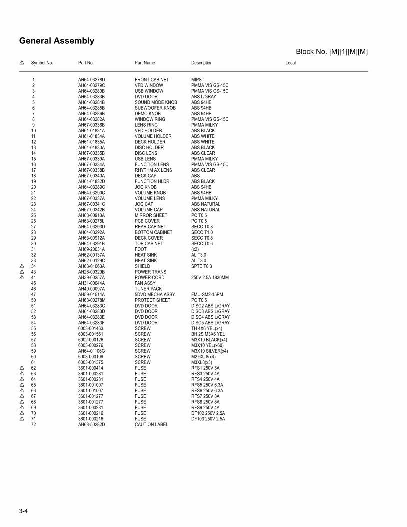
General AssemblyBlock No. [M][1][M][M]
Symbol No. Part No. Part Name Description Local
1 AH64-03278D FRONT CABINET MIPS 2 AH64-03279C VFD WINDOW PMMA VIS GS-15C 3 AH64-03280B USB WINDOW PMMA VIS GS-15C 4 AH64-03283B DVD DOOR ABS L/GRAY 5 AH64-03284B SOUND MODE KNOB ABS 94HB 6 AH64-03285B SUBWOOFER KNOB ABS 94HB 7 AH64-03286B DEMO KNOB ABS 94HB 8 AH64-03282A WINDOW RING PMMA VIS GS-15C 9 AH67-00336B LENS RING PMMA MILKY10 AH61-01831A VFD HOLDER ABS BLACK11 AH61-01834A VOLUME HOLDER ABS WHITE12 AH61-01835A DECK HOLDER ABS WHITE13 AH61-01833A DISC HOLDER ABS BLACK14 AH67-00335B DISC LENS ABS CLEAR15 AH67-00339A USB LENS PMMA MILKY16 AH67-00334A FUNCTION LENS PMMA VIS GS-15C17 AH67-00338B RHYTHM AX LENS ABS CLEAR18 AH67-00340A DECK CAP ABS19 AH61-01832D FUNCTION HLDR ABS BLACK20 AH64-03289C JOG KNOB ABS 94HB21 AH64-03290C VOLUME KNOB ABS 94HB22 AH67-00337A VOLUME LENS PMMA MILKY23 AH67-00341C JOG CAP ABS NATURAL24 AH67-00342B VOLUME CAP ABS NATURAL25 AH63-00913A MIRROR SHEET PC T0.526 AH63-00278L PCB COVER PC T0.527 AH64-03293D REAR CABINET SECC T0.828 AH64-03292A BOTTOM CABINET SECC T1.029 AH63-00912A DECK COVER SECC T0.830 AH64-03291B TOP CABINET SECC T0.631 AH69-20031A FOOT (x2)32 AH62-00137A HEAT SINK AL T3.033 AH62-00129C HEAT SINK AL T3.0
34 AH63-01063A SHIELD SPTE T0.3 43 AH26-00329B POWER TRANS 44 AH39-00257A POWER CORD 250V 2.5A 1830MM
45 AH31-00044A FAN ASSY46 AH40-00097A TUNER PACK47 AH59-01514A 5DVD MECHA ASSY FMU-SM2-15PM50 AH63-00278M PROTECT SHEET PC T0.551 AH64-03283C DVD DOOR DISC2 ABS L/GRAY52 AH64-03283D DVD DOOR DISC3 ABS L/GRAY53 AH64-03283E DVD DOOR DISC4 ABS L/GRAY54 AH64-03283F DVD DOOR DISC5 ABS L/GRAY55 6003-001463 SCREW TH 4X6 YEL(x4)56 6003-001561 SCREW BH 2S M3X6 YEL57 6002-000126 SCREW M3X10 BLACK(x4)58 6003-000276 SCREW M3X10 YEL(x60)59 AH64-01106G SCREW M3X10 SILVER(x4)60 6003-000109 SCREW M2.6XL8(x4)61 6003-001375 SCREW M3XL8(x3)
62 3601-000414 FUSE RFS1 250V 5A 63 3601-000281 FUSE RFS3 250V 4A 64 3601-000281 FUSE RFS4 250V 4A 65 3601-001007 FUSE RFS5 250V 6.3A 66 3601-001007 FUSE RFS6 250V 6.3A 67 3601-001277 FUSE RFS7 250V 8A 68 3601-001277 FUSE RFS8 250V 8A 69 3601-000281 FUSE RFS9 250V 4A 70 3601-000216 FUSE DF102 250V 2.5A 71 3601-000216 FUSE DF103 250V 2.5A
72 AH68-50282D CAUTION LABEL
3-4

Electrical parts listMain board
Block No. [0][1]Symbol No. Part No. Part Name Description Local
AIC01 324 IC 1201-000471AIC02 324 IC 1201-000471AIC03 4558 IC 1201-000461CIC01 78R05 IC 1203-001006EIC01 TDA7442D IC 1204-001776EIC02 4558 IC 1201-000461HIC01 4556 IC 1201-001285SIC01 JCV8011-TLM-E IC 1204-002268SIC02 4558 IC 1201-000461
AQ101 KTC945B TRANSISTOR 0501-002409AQ102 KTC945B TRANSISTOR 0501-002409AQ103 KTC945B TRANSISTOR 0501-002409CQ01L KTC2874-B TRANSISTOR 0501-002436CQ01R KTC2874-B TRANSISTOR 0501-002436EQ02 KSR2003 TRANSISTOR 0504-000145EQ03 KSR1003 TRANSISTOR 0504-000118EQ04 KSR2003 TRANSISTOR 0504-000145EQ01L KTC2874-B TRANSISTOR 0501-002436EQ01R KTC2874-B TRANSISTOR 0501-002436EQ02L KTC2874-B TRANSISTOR 0501-002436EQ02R KTC2874-B TRANSISTOR 0501-002436EQ101 KTC945B TRANSISTOR 0501-002409FQ101 KSC2331-Y TRANSISTOR 0501-000369FQ102 KTA1273 TRANSISTOR 0501-000422HQ02 KTC2874-B TRANSISTOR 0501-002436HQ01L KTC2874-B TRANSISTOR 0501-002436HQ01R KTC2874-B TRANSISTOR 0501-002436PQ109 KSD1691 TRANSISTOR 0502-001048SQ01 KTC2874-B TRANSISTOR 0501-002436SQ02 KRA104M TRANSISTOR 0504-001175
AD101 1N4148 DIODE 0401-000005AD102 1N4148 DIODE 0401-000005AD103 1N4148 DIODE 0401-000005AD104 1N4148 DIODE 0401-000005CD101 1N4148 DIODE 0401-000005CD102 1N4148 DIODE 0401-000005ED101 1N4148 DIODE 0401-000005ED102 1N4148 DIODE 0401-000005EZD01 MTZJ9.1C Z DIODE 0403-001170SZD01 MTZJ9.1C Z DIODE 0403-001170
AC01L 2202-000263 C CAPACITOR 470pF 50VAC01R 2202-000263 C CAPACITOR 470pF 50VAC101 2301-000216 M CAPACITOR 220nF 50VAC102 2301-000474 M CAPACITOR 8.2nF 50VAC103 2301-000390 M CAPACITOR 15nF 50VAC104 2201-000021 C CAPACITOR 100nF 50VAC105 2301-000419 M CAPACITOR 27nF 50VAC106 2301-000449 M CAPACITOR 47nF 50VAC107 2301-000375 M CAPACITOR 100nF 50VAC108 2301-000375 M CAPACITOR 100nF 50VAC109 2301-000419 M CAPACITOR 27nF 50VAC110 2301-000216 M CAPACITOR 220nF 50VAC111 2201-000146 C CAPACITOR 0.1nFAE101 2401-000042 E CAPACITOR 100uF 16VAE102 2401-000042 E CAPACITOR 100uF 16VAE103 2401-000027 E CAPACITOR 4.7uF 50VAE104 2401-000027 E CAPACITOR 4.7uF 50VAE107 2401-000042 E CAPACITOR 100uF 16VAE109 2401-001975 E CAPACITOR 47uF 16VAE110 2401-000027 E CAPACITOR 4.7uF 50VAE111 2401-001912 E CAPACITOR 1uF 50VAE112 2401-000042 E CAPACITOR 100uF 16VAE114 2401-001975 E CAPACITOR 47uF 16VAE115 2401-001975 E CAPACITOR 47uF 16VAE116 2401-000651 E CAPACITOR 2.2uF 50VAE117 2401-000027 E CAPACITOR 4.7uF 50VCE101 2401-000042 E CAPACITOR 100uF 16VEC07L 2301-000454 M CAPACITOR 5.6nF 50VEC07R 2301-000454 M CAPACITOR 5.6nF 50V
EC08L 2301-000216 M CAPACITOR 220nF 50VEC08R 2301-000216 M CAPACITOR 220nF 50VEC09L 2301-000216 M CAPACITOR 220nF 50VEC09R 2301-000216 M CAPACITOR 220nF 50VEC101 2301-000361 M CAPACITOR 1.2nF 50VEC102 2301-000375 M CAPACITOR 100nF 50VEC103 2201-000021 C CAPACITOR 100nF 50VEC11L 2201-000573 C CAPACITOR 0.047nF 50VEC11R 2201-000573 C CAPACITOR 0.047nF 50VEC12L 2201-000379 C CAPACITOR 22nF 50VEC12R 2201-000379 C CAPACITOR 22nF 50VEC13L 2201-000379 C CAPACITOR 22nF 50VEC13R 2201-000379 C CAPACITOR 22nF 50VEE25 2401-001912 E CAPACITOR 1uF 50VEE01L 2401-001912 E CAPACITOR 1uF 50VEE01R 2401-001912 E CAPACITOR 1uF 50VEE02L 2401-001912 E CAPACITOR 1uF 50VEE02R 2401-001912 E CAPACITOR 1uF 50VEE03L 2401-001912 E CAPACITOR 1uF 50VEE03R 2401-001912 E CAPACITOR 1uF 50VEE04L 2401-001912 E CAPACITOR 1uF 50VEE04R 2401-001912 E CAPACITOR 1uF 50VEE05L 2401-001912 E CAPACITOR 1uF 50VEE05R 2401-001912 E CAPACITOR 1uF 50VEE06L 2401-000651 E CAPACITOR 2.2uF 50VEE06R 2401-000651 E CAPACITOR 2.2uF 50VEE07L 2401-000651 E CAPACITOR 2.2uF 50VEE07R 2401-000651 E CAPACITOR 2.2uF 50VEE08L 2401-001912 E CAPACITOR 1uF 50VEE08R 2401-001912 E CAPACITOR 1uF 50VEE09L 2401-000455 E CAPACITOR 10uF 35VEE09R 2401-000455 E CAPACITOR 10uF 35VEE101 2401-000480 E CAPACITOR 10uF 50VEE102 2401-001975 E CAPACITOR 47uF 16VEE103 2401-000832 E CAPACITOR 220uF 25VEE104 2401-000042 E CAPACITOR 100uF 16VEE105 2401-000042 E CAPACITOR 100uF 16VEE106 2401-000048 E CAPACITOR 47uF 25VEE107 2401-000027 E CAPACITOR 4.7uF 50VEE108 2401-000027 E CAPACITOR 4.7uF 50VEE109 2401-000759 E CAPACITOR 220nF 50VEE110 2401-000048 E CAPACITOR 47uF 25VFC101 2401-001975 E CAPACITOR 47uF 16VFC102 2401-000048 E CAPACITOR 47uF 25VHC01L 2201-000863 C CAPACITOR 0.68nF 50VHC01R 2201-000863 C CAPACITOR 0.68nF 50VHC02L 2201-000146 C CAPACITOR 0.1nFHC02R 2201-000146 C CAPACITOR 0.1nFHC03L 2201-000389 C CAPACITOR 0.022nFHC03R 2201-000389 C CAPACITOR 0.022nFHE01L 2401-001912 E CAPACITOR 1uF 50VHE01R 2401-001912 E CAPACITOR 1uF 50VHE02L 2401-001164 E CAPACITOR 33uF 16VHE02R 2401-001164 E CAPACITOR 33uF 16VHE101 2401-000832 E CAPACITOR 220uF 25VHE102 2401-000832 E CAPACITOR 220uF 25VHE103 2401-001975 E CAPACITOR 47uF 16VPE215 2401-002042 E CAPACITOR 220uF 10VSC01 2301-000419 M CAPACITOR 27nF 50VSE04 2401-000651 E CAPACITOR 2.2uF 50VSE05 2401-000651 E CAPACITOR 2.2uF 50VSE08 2401-000480 E CAPACITOR 10uF 50VSE09 2401-000027 E CAPACITOR 4.7uF 50VSE10 2401-000480 E CAPACITOR 10uF 50VSE11 2401-000480 E CAPACITOR 10uF 50VSE12 2401-000480 E CAPACITOR 10uF 50VSE13 2401-000027 E CAPACITOR 4.7uF 50VSE14 2401-000759 E CAPACITOR 220nF 50VSE15 2401-000651 E CAPACITOR 2.2uF 50VSE16 2401-001645 E CAPACITOR 0.68uF 50VSE17 2401-000048 E CAPACITOR 47uF 25VSE01L 2401-000027 E CAPACITOR 4.7uF 50VSE01R 2401-000027 E CAPACITOR 4.7uF 50VSE02L 2401-000048 E CAPACITOR 47uF 25VSE02R 2401-000048 E CAPACITOR 47uF 25VSE03L 2401-000480 E CAPACITOR 10uF 50V
Symbol No. Part No. Part Name Description Local
3-5

SE03R 2401-000480 E CAPACITOR 10uF 50VSE06L 2401-001938 E CAPACITOR 22uF 25VSE06R 2401-001938 E CAPACITOR 22uF 25VSE07L 2401-000480 E CAPACITOR 10uF 50VSE07R 2401-000480 E CAPACITOR 10uF 50V
AR01L 2001-000522 C RESISTOR 22KΩ 1/8WAR01R 2001-000522 C RESISTOR 22KΩ 1/8WAR02L 2001-000786 C RESISTOR 47KΩ 1/8WAR02R 2001-000786 C RESISTOR 47KΩ 1/8WAR03L 2001-000508 C RESISTOR 220KΩ 1/8WAR03R 2001-000508 C RESISTOR 220KΩ 1/8WAR101 2001-000563 C RESISTOR 27KΩ 1/8WAR102 2001-000563 C RESISTOR 27KΩ 1/8WAR103 2001-000548 C RESISTOR 270KΩ 1/8WAR104 2001-000273 C RESISTOR 100KΩ 1/8WAR105 2001-000273 C RESISTOR 100KΩ 1/8WAR106 2001-000522 C RESISTOR 22KΩ 1/8WAR107 2001-000522 C RESISTOR 22KΩ 1/8WAR108 2001-000281 C RESISTOR 100Ω 1/8WAR109 2001-000281 C RESISTOR 100Ω 1/8WAR10L 2001-000793 C RESISTOR 47Ω 1/8WAR10R 2001-000793 C RESISTOR 47Ω 1/8WAR110 2001-000273 C RESISTOR 100KΩ 1/8WAR111 2001-000273 C RESISTOR 100KΩ 1/8WAR112 2001-000273 C RESISTOR 100KΩ 1/8WAR114 2001-000864 C RESISTOR 56KΩ 1/8WAR115 2001-000258 C RESISTOR 1.8KΩ 1/8WAR116 2001-000977 C RESISTOR 8.2KΩ 1/8WAR118 2001-000508 C RESISTOR 220KΩ 1/8WAR119 2001-000281 C RESISTOR 100Ω 1/8WAR11L 2001-000290 C RESISTOR 10KΩ 1/8WAR11R 2001-000290 C RESISTOR 10KΩ 1/8WAR121 2001-000802 C RESISTOR 5.6KΩ 1/8WAR122 2001-000522 C RESISTOR 22KΩ 1/8WAR123 2001-000258 C RESISTOR 1.8KΩ 1/8WAR124 2001-000331 C RESISTOR 12KΩ 1/8WAR125 2001-000522 C RESISTOR 22KΩ 1/8WAR126 2001-000522 C RESISTOR 22KΩ 1/8WAR127 2001-000890 C RESISTOR 6.8KΩ 1/8WAR128 2001-000563 C RESISTOR 27KΩ 1/8WAR129 2001-000281 C RESISTOR 100Ω 1/8WAR130 2001-000281 C RESISTOR 100Ω 1/8WAR131 2001-000281 C RESISTOR 100Ω 1/8WAR132 2001-000508 C RESISTOR 220KΩ 1/8WAR133 2001-000449 C RESISTOR 2.2KΩ 1/8WAR134 2001-001000 C RESISTOR 82KΩ 1/8WAR135 2001-000273 C RESISTOR 100KΩ 1/8WAR136 2001-000273 C RESISTOR 100KΩ 1/8WAR137 2001-000786 C RESISTOR 47KΩ 1/8WAR138 2001-000786 C RESISTOR 47KΩ 1/8WAR139 2001-000554 C RESISTOR 270Ω 1/8WAR140 2001-000802 C RESISTOR 5.6KΩ 1/8WAR141 2001-000027 C RESISTOR 100Ω 1/4WAR142 2001-000027 C RESISTOR 100Ω 1/4WCR01L 2001-000864 C RESISTOR 56KΩ 1/8WCR01R 2001-000864 C RESISTOR 56KΩ 1/8WCR02L 2001-000411 C RESISTOR 18KΩ 1/8WCR02R 2001-000411 C RESISTOR 18KΩ 1/8WCR03L 2001-000591 C RESISTOR 3.3KΩ 1/8WCR03R 2001-000591 C RESISTOR 3.3KΩ 1/8WER25 2001-000290 C RESISTOR 10KΩ 1/8WER02L 2001-000591 C RESISTOR 3.3KΩ 1/8WER02R 2001-000591 C RESISTOR 3.3KΩ 1/8WER05L 2001-000515 C RESISTOR 220Ω 1/8WER05R 2001-000515 C RESISTOR 220Ω 1/8WER06L 2001-000786 C RESISTOR 47KΩ 1/8WER06R 2001-000786 C RESISTOR 47KΩ 1/8WER07L 2001-000734 C RESISTOR 4.7KΩ 1/8WER07R 2001-000734 C RESISTOR 4.7KΩ 1/8WER08L 2001-000786 C RESISTOR 47KΩ 1/8WER08R 2001-000786 C RESISTOR 47KΩ 1/8WER09L 2001-000331 C RESISTOR 12KΩ 1/8WER09R 2001-000331 C RESISTOR 12KΩ 1/8WER101 2001-000515 C RESISTOR 220Ω 1/8WER102 2001-000515 C RESISTOR 220Ω 1/8WER103 2001-000023 C RESISTOR 47Ω 1/4WER104 2001-000022 C RESISTOR 33Ω 1/2W
Symbol No. Part No. Part Name Description Local
ER105 2001-000591 C RESISTOR 3.3KΩ 1/8WER109 2001-000290 C RESISTOR 10KΩ 1/8WER10L 2001-000273 C RESISTOR 100KΩ 1/8WER10R 2001-000273 C RESISTOR 100KΩ 1/8WER110 2001-000773 C RESISTOR 470KΩ 1/8WER111 2001-000515 C RESISTOR 220Ω 1/8WER112 2001-000645 C RESISTOR 330KΩ 1/8WER113 2001-000989 C RESISTOR 820KΩ 1/8WER114 2001-000786 C RESISTOR 47KΩ 1/8WER13L 2001-000356 C RESISTOR 150KΩ 1/8WER13R 2001-000356 C RESISTOR 150KΩ 1/8WER14L 2001-000008 C RESISTOR 15KΩ 1/8WER14R 2001-000008 C RESISTOR 15KΩ 1/8WER15L 2001-000290 C RESISTOR 10KΩ 1/8WER15R 2001-000290 C RESISTOR 10KΩ 1/8WER16L 2001-000003 C RESISTOR 330Ω 1/8WER16R 2001-000003 C RESISTOR 330Ω 1/8WER17L 2001-000003 C RESISTOR 330Ω 1/8WER17R 2001-000003 C RESISTOR 330Ω 1/8WER19L 2001-000591 C RESISTOR 3.3KΩ 1/8WER19R 2001-000591 C RESISTOR 3.3KΩ 1/8WER20L 2001-000864 C RESISTOR 56KΩ 1/8WER20R 2001-000864 C RESISTOR 56KΩ 1/8WER21L 2001-001000 C RESISTOR 82KΩ 1/8WER21R 2001-001000 C RESISTOR 82KΩ 1/8WER22L 2001-000522 C RESISTOR 22KΩ 1/8WER22R 2001-000522 C RESISTOR 22KΩ 1/8WER23L 2001-000429 C RESISTOR 1KΩ 1/8WER23R 2001-000429 C RESISTOR 1KΩ 1/8WER24L 2001-000786 C RESISTOR 47KΩ 1/8WER24R 2001-000786 C RESISTOR 47KΩ 1/8WER25L 2001-000591 C RESISTOR 3.3KΩ 1/8WER25R 2001-000591 C RESISTOR 3.3KΩ 1/8WFR101 2001-000429 C RESISTOR 1KΩ 1/8WFR102 2001-000449 C RESISTOR 2.2KΩ 1/8WFR103 2001-000025 C RESISTOR 75Ω 1/4WFR104 2001-000522 C RESISTOR 22KΩ 1/8WFR222 2001-000855 C RESISTOR 560Ω 1/4WHR01L 2001-000449 C RESISTOR 2.2KΩ 1/8WHR01R 2001-000449 C RESISTOR 2.2KΩ 1/8WHR02L 2001-000449 C RESISTOR 2.2KΩ 1/8WHR02R 2001-000449 C RESISTOR 2.2KΩ 1/8WHR03L 2001-000734 C RESISTOR 4.7KΩ 1/8WHR03R 2001-000734 C RESISTOR 4.7KΩ 1/8WHR04L 2001-000290 C RESISTOR 10KΩ 1/8WHR04R 2001-000290 C RESISTOR 10KΩ 1/8WHR05L 2001-000019 C RESISTOR 10Ω 1/2WHR05R 2001-000019 C RESISTOR 10Ω 1/2WHR06L 2001-000591 C RESISTOR 3.3KΩ 1/8WHR06R 2001-000591 C RESISTOR 3.3KΩ 1/8WHR101 2001-000028 C RESISTOR 100Ω 1/2WHR102 2001-000028 C RESISTOR 100Ω 1/2WPR222 2001-000273 C RESISTOR 100KΩ 1/8WPR223 2001-000062 C RESISTOR 470Ω 1/4WSR01 2001-000773 C RESISTOR 470KΩ 1/8WSR02 2001-000773 C RESISTOR 470KΩ 1/8WSR03 2001-000281 C RESISTOR 100Ω 1/8WSR04 2001-000008 C RESISTOR 15KΩ 1/8WSR05 2001-000802 C RESISTOR 5.6KΩ 1/8WSR06 2001-000723 C RESISTOR 4.3KΩ1/8WSR07 2001-000273 C RESISTOR 100KΩ 1/8WSR08 2001-000290 C RESISTOR 10KΩ 1/8WSR09 2001-000734 C RESISTOR 4.7KΩ 1/8WSR12 2001-000591 C RESISTOR 3.3KΩ 1/8WSR13 2001-000023 C RESISTOR 47Ω 1/4WSR18 2001-000281 C RESISTOR 100Ω 1/8WSR19 2001-000281 C RESISTOR 100Ω 1/8WSR20 2001-000244 C RESISTOR 1.5MΩ 1/8WSR21 2001-000290 C RESISTOR 10KΩ 1/8WSR10L 2001-000331 C RESISTOR 12KΩ 1/8WSR10R 2001-000331 C RESISTOR 12KΩ 1/8WSR11L 2001-000449 C RESISTOR 2.2KΩ 1/8WSR11R 2001-000449 C RESISTOR 2.2KΩ 1/8WSR14L 2001-000290 C RESISTOR 10KΩ 1/8WSR14R 2001-000290 C RESISTOR 10KΩ 1/8WSR15L 2001-000290 C RESISTOR 10KΩ 1/8WSR15R 2001-000290 C RESISTOR 10KΩ 1/8WSR16L 2001-000802 C RESISTOR 5.6KΩ 1/8W
Symbol No. Part No. Part Name Description Local
3-6

Front boardBlock No. [0][2]
SR16R 2001-000802 C RESISTOR 5.6KΩ 1/8WSR17L 2001-000734 C RESISTOR 4.7KΩ 1/8WSR17R 2001-000734 C RESISTOR 4.7KΩ 1/8W
AW104 AH39-00791A CONNECTOR WIRE 10P for AMP AW105
CW101 3711-005905 CONNECTOR 2PCW102 3710-002254 CONNECTOR 12P 2mmCW103 3708-000412 CONNECTOR 12P 1.25mmCW104 3708-000347 CONNECTOR 10P 1MMCW105 3711-005905 CONNECTOR 2PCW106 3708-000189 CONNECTOR 17P 1.25mmFW101 AH39-20008Q CONNECTOR WIRE 2P for AMP
FAN102GND1 AH39-50001K HARNESS WIRE 140mm BLKGND2 AH65-30013A CLAMP CORDXXXXX 3811-000122 PVC WIRE 300V 150mmXXXXX 6003-001375 SCREW M3XL8XXXXX AH61-40014A SUPPORT RIVET (x2)XXXXX AH62-00099A HEAT SINKXXXXX AH62-00147A HEAT SINK
Symbol No. Part No. Part Name Description Local
UIC01 AH11-00167A MASK ROM LC876B64C-56L0UIC02 LC709006A IC 1205-002632UIC03 CM102 IC 0904-001968
FQ301 KTC8050 TRANSISTOR 0501-002375FQ302 KTC8050 TRANSISTOR 0501-002375FQ303 KSD1691 TRANSISTOR 0502-001048FQ304 KSR1003 TRANSISTOR 0504-000118UQ101 KTC945B TRANSISTOR 0501-002409
FD201 1N4002 DIODE 0402-000127FD204 1N4002 DIODE 0402-000127FD301 1N4002 DIODE 0402-000127FZ301 MTZJ5.6B Z DIODE 0403-000509LD201 0601-001739 LED REDLD202 0601-001739 LED REDLD203 0601-001739 LED REDLD204 0601-001739 LED REDLD205 0601-001739 LED REDLD206 0601-001739 LED REDLD207 0601-001739 LED REDLD208 0601-001739 LED REDLD209 0601-001739 LED REDLD301 0601-001739 LED REDLD302 0601-001739 LED REDLD303 0601-001739 LED REDLD304 0601-001739 LED REDLD305 0601-001739 LED REDLD306 0601-001739 LED REDLD307 0601-001739 LED REDLD308 0601-001739 LED REDLD309 0601-001739 LED REDLD310 0601-001739 LED REDLD311 0601-001739 LED REDLED12 0601-001739 LED REDLED13 0601-001739 LED REDUD02 1N4148 DIODE 0401-000005UD101 1N4148 DIODE 0401-000005UD102 1N4148 DIODE 0401-000005UD103 1N4002 DIODE 0402-000127UD104 1N4002 DIODE 0402-000127UD105 1N4148 DIODE 0401-000005
FC01L 2202-000806 C CAPACITOR 220pF 50VFC01R 2202-000806 C CAPACITOR 220pF 50VFC02L 2202-000806 C CAPACITOR 220pF 50VFC02R 2202-000806 C CAPACITOR 220pF 50VFC201 2201-000982 C CAPACITOR 10nF
Symbol No. Part No. Part Name Description Local
FC204 2201-000565 C CAPACITOR 47nF 50VFC301 2202-000121 C CAPACITOR 0.1nF 50VFC302 2202-000121 C CAPACITOR 0.1nF 50VFC303 2202-000786 C CAPACITOR 0.01nF 50VFC304 2202-000786 C CAPACITOR 0.01nF 50VFE200 2401-000240 E CAPACITOR 100uF 10VFE301 2401-000832 E CAPACITOR 220uF 25VFE302 2401-001952 E CAPACITOR 4.7uF 50VFE303 2401-000480 E CAPACITOR 10uF 50VFE304 2401-000414 E CAPACITOR 10uF 16VFE305 2401-000414 E CAPACITOR 10uF 16VFE30L 2401-002042 E CAPACITOR 220uF 10VFE30R 2401-002042 E CAPACITOR 220uF 10VUC101 2201-000982 C CAPACITOR 10nFUC102 2201-000565 C CAPACITOR 47nF 50VUC103 2201-000389 C CAPACITOR 0.022nFUC104 2201-000389 C CAPACITOR 0.022nFUC105 2201-000565 C CAPACITOR 47nF 50VUC106 2201-000565 C CAPACITOR 47nF 50VUC107 2201-000017 C CAPACITOR 1nF 50VUE101 2401-000651 E CAPACITOR 2.2uF 50VUE102 2401-000759 E CAPACITOR 220nF 50VUE103 2401-000118 E CAPACITOR 1000uF 10VUE104 2401-000240 E CAPACITOR 100uF 10V
FR01L 2001-000290 C RESISTOR 10KΩ 1/8WFR01R 2001-000290 C RESISTOR 10KΩ 1/8WFR201 2001-000995 C RESISTOR 820Ω 1/8WFR202 2001-000429 C RESISTOR 1KΩ 1/8WFR203 2001-000221 C RESISTOR 1.2KΩ 1/8WFR204 2001-000241 C RESISTOR 1.5KΩ 1/8WFR205 2001-000258 C RESISTOR 1.8KΩ 1/8WFR206 2001-000449 C RESISTOR 2.2KΩ 1/8WFR207 2001-000591 C RESISTOR 3.3KΩ 1/8WFR208 2001-000734 C RESISTOR 4.7KΩ 1/8WFR209 2001-000890 C RESISTOR 6.8KΩ 1/8WFR210 2001-000995 C RESISTOR 820Ω 1/8WFR211 2001-000429 C RESISTOR 1KΩ 1/8WFR212 2001-000221 C RESISTOR 1.2KΩ 1/8WFR213 2001-000241 C RESISTOR 1.5KΩ 1/8WFR214 2001-000258 C RESISTOR 1.8KΩ 1/8WFR215 2001-000449 C RESISTOR 2.2KΩ 1/8WFR216 2001-000591 C RESISTOR 3.3KΩ 1/8WFR217 2001-000034 C RESISTOR 220Ω 1/4WFR218 2001-000034 C RESISTOR 220Ω 1/4WFR219 2001-000034 C RESISTOR 220Ω 1/4WFR220 2001-000034 C RESISTOR 220Ω 1/4WFR221 2001-000034 C RESISTOR 220Ω 1/4WFR222 2001-000855 C RESISTOR 560Ω 1/4WFR223 2001-000034 C RESISTOR 220Ω 1/4WFR224 2001-000034 C RESISTOR 220Ω 1/4WFR225 2001-000034 C RESISTOR 220Ω 1/4WFR301 2001-000034 C RESISTOR 220Ω 1/4WFR302 2001-000034 C RESISTOR 220Ω 1/4WFR303 2001-000034 C RESISTOR 220Ω 1/4WFR304 2001-000034 C RESISTOR 220Ω 1/4WFR305 2001-000034 C RESISTOR 220Ω 1/4WFR306 2001-000034 C RESISTOR 220Ω 1/4WFR307 2001-000034 C RESISTOR 220Ω 1/4WFR308 2001-000034 C RESISTOR 220Ω 1/4WFR309 2001-000034 C RESISTOR 220Ω 1/4WFR30L 2001-000411 C RESISTOR 18KΩ 1/8WFR30R 2001-000411 C RESISTOR 18KΩ 1/8WFR310 2001-000034 C RESISTOR 220Ω 1/4WFR311 2001-000995 C RESISTOR 820Ω 1/8WFR312 2001-000429 C RESISTOR 1KΩ 1/8WFR313 2001-000221 C RESISTOR 1.2KΩ 1/8WFR314 2001-000241 C RESISTOR 1.5KΩ 1/8WFR315 2001-000258 C RESISTOR 1.8KΩ 1/8WFR316 2001-000449 C RESISTOR 2.2KΩ 1/8WFR317 2001-000734 C RESISTOR 4.7KΩ 1/8WFR318 2001-000734 C RESISTOR 4.7KΩ 1/8WFR319 2001-000119 C RESISTOR 680Ω 1/4WFR320 2001-000241 C RESISTOR 1.5KΩ 1/8WFR321 2001-000527 C RESISTOR 22Ω 1/8WFR322 2001-000527 C RESISTOR 22Ω 1/8WFR323 2001-000435 C RESISTOR 1MΩ 1/8WFR324 2001-000290 C RESISTOR 10KΩ 1/8W
Symbol No. Part No. Part Name Description Local
3-7

FR325 2001-000034 C RESISTOR 220Ω 1/4WFR326 2001-000034 C RESISTOR 220Ω 1/4WFR327 2001-000034 C RESISTOR 220Ω 1/4WUR001 2001-000290 C RESISTOR 10KΩ 1/8WUR101 2001-000734 C RESISTOR 4.7KΩ 1/8WUR102 2001-000734 C RESISTOR 4.7KΩ 1/8WUR103 2001-000734 C RESISTOR 4.7KΩ 1/8WUR104 2001-000734 C RESISTOR 4.7KΩ 1/8WUR105 2001-000734 C RESISTOR 4.7KΩ 1/8WUR106 2001-000734 C RESISTOR 4.7KΩ 1/8WUR107 2001-000734 C RESISTOR 4.7KΩ 1/8WUR108 2001-000734 C RESISTOR 4.7KΩ 1/8WUR109 2001-000734 C RESISTOR 4.7KΩ 1/8WUR110 2001-000734 C RESISTOR 4.7KΩ 1/8WUR111 2001-000734 C RESISTOR 4.7KΩ 1/8WUR112 2001-000734 C RESISTOR 4.7KΩ 1/8WUR113 2001-000786 C RESISTOR 47KΩ 1/8WUR114 2001-000786 C RESISTOR 47KΩ 1/8WUR115 2001-000786 C RESISTOR 47KΩ 1/8WUR116 2001-000786 C RESISTOR 47KΩ 1/8WUR117 2001-000786 C RESISTOR 47KΩ 1/8WUR118 2001-000786 C RESISTOR 47KΩ 1/8WUR119 2001-000786 C RESISTOR 47KΩ 1/8WUR120 2001-000786 C RESISTOR 47KΩ 1/8WUR121 2001-000786 C RESISTOR 47KΩ 1/8WUR122 2001-000786 C RESISTOR 47KΩ 1/8WUR123 2001-000786 C RESISTOR 47KΩ 1/8WUR124 2001-000786 C RESISTOR 47KΩ 1/8WUR125 2001-000786 C RESISTOR 47KΩ 1/8WUR126 2001-000786 C RESISTOR 47KΩ 1/8WUR127 2001-000786 C RESISTOR 47KΩ 1/8WUR128 2001-000786 C RESISTOR 47KΩ 1/8WUR129 2001-000786 C RESISTOR 47KΩ 1/8WUR130 2001-000786 C RESISTOR 47KΩ 1/8WUR131 2001-000786 C RESISTOR 47KΩ 1/8WUR132 2001-000786 C RESISTOR 47KΩ 1/8WUR133 2001-000786 C RESISTOR 47KΩ 1/8WUR134 2001-000786 C RESISTOR 47KΩ 1/8WUR135 2001-000786 C RESISTOR 47KΩ 1/8WUR136 2001-000786 C RESISTOR 47KΩ 1/8WUR137 2001-000786 C RESISTOR 47KΩ 1/8WUR138 2001-000786 C RESISTOR 47KΩ 1/8WUR139 2001-000786 C RESISTOR 47KΩ 1/8WUR140 2001-000786 C RESISTOR 47KΩ 1/8WUR141 2001-000786 C RESISTOR 47KΩ 1/8WUR142 2001-000786 C RESISTOR 47KΩ 1/8WUR143 2001-000786 C RESISTOR 47KΩ 1/8WUR144 2001-000786 C RESISTOR 47KΩ 1/8WUR145 2001-000786 C RESISTOR 47KΩ 1/8WUR146 2001-000786 C RESISTOR 47KΩ 1/8WUR147 2001-000786 C RESISTOR 47KΩ 1/8WUR148 2001-000786 C RESISTOR 47KΩ 1/8WUR149 2001-000786 C RESISTOR 47KΩ 1/8WUR150 2001-000429 C RESISTOR 1KΩ 1/8WUR151 2001-000290 C RESISTOR 10KΩ 1/8WUR152 2001-000290 C RESISTOR 10KΩ 1/8WUR153 2001-000290 C RESISTOR 10KΩ 1/8WUR154 2001-000290 C RESISTOR 10KΩ 1/8WUR155 2001-000290 C RESISTOR 10KΩ 1/8WUR156 2001-000290 C RESISTOR 10KΩ 1/8WUR157 2001-000290 C RESISTOR 10KΩ 1/8WUR158 2001-000290 C RESISTOR 10KΩ 1/8WUR159 2001-000290 C RESISTOR 10KΩ 1/8WUR160 2001-000290 C RESISTOR 10KΩ 1/8WUR161 2001-000429 C RESISTOR 1KΩ 1/8WUR162 2001-000429 C RESISTOR 1KΩ 1/8WUR163 2001-000429 C RESISTOR 1KΩ 1/8WUR172 2001-000027 C RESISTOR 100Ω 1/4WUR173 2001-000281 C RESISTOR 100Ω 1/8WUR174 2001-000027 C RESISTOR 100Ω 1/4WUR175 2001-000281 C RESISTOR 100Ω 1/8WUR176 2001-000027 C RESISTOR 100Ω 1/4WUR177 2001-000295 C RESISTOR 10MΩ 1/8WUR178 2001-000850 C RESISTOR 560KΩ 1/8WUR179 2001-000435 C RESISTOR 1MΩ 1/8WUR180 2001-000449 C RESISTOR 2.2KΩ 1/8WUR181 2001-000734 C RESISTOR 4.7KΩ 1/8WUR182 2001-000508 C RESISTOR 220KΩ 1/8W
Symbol No. Part No. Part Name Description Local
UR183 2001-000793 C RESISTOR 47Ω 1/8WUR184 2001-000734 C RESISTOR 4.7KΩ 1/8WUR186 2001-000780 C RESISTOR 470KΩ 1/8WUR187 2001-000780 C RESISTOR 470KΩ 1/8W
AJACK1 3722-001588 PHONE JACK 7P 3.6PI AG BLKBEAD1 3301-000297 FERRITE BEADSBEAD2 3301-000297 FERRITE BEADSBZ101 3002-001134 BUZZER 85DB 12VFL301 3301-000297 FERRITE BEADSFL302 3301-000297 FERRITE BEADSFW101 3708-000492 CONNECTOR 9P 1.25mmFW102 3708-001696 CONNECTOR 24PFW201 3708-001577 CONNECTOR 30P 1.25mmFW202 3708-001696 CONNECTOR 24PFW301 3708-001488 CONNECTOR 30P 1.25mmFW302 3710-002050 CONNECTOR 12PFW303 3710-002050 CONNECTOR 12PFW304 3710-002050 CONNECTOR 12PFW305 3722-002292 USB JACK 4P/1PFW306 AH39-00096D CONNECTOR WIRE 3P for FRONT
FW307FW307 3711-000906 CONNECTOR 3P 1R 2mmFW308 3711-001136 CONNECTOR 8PFW309 AH39-00060C CONNECTOR WIRE 8P for FRONT
FW308GND2 AH39-50001L HARNESS WIRE RING4 200MM
BLKHJACK1 3722-001588 PHONE JACK 7P 3.6PI AG BLKPS102 3406-001050 ROTARY SWITCH 5V DC 0.5mA
12mmREYE1 0609-001189 REMOCON MODULE HORIZONTAL
16.4mmSW201 3404-000165 TACT SWITCH 12V 50mASW202 3404-000165 TACT SWITCH 12V 50mASW203 3404-000165 TACT SWITCH 12V 50mASW204 3404-000165 TACT SWITCH 12V 50mASW205 3404-000165 TACT SWITCH 12V 50mASW206 3404-000165 TACT SWITCH 12V 50mASW207 3404-000165 TACT SWITCH 12V 50mASW208 3404-000165 TACT SWITCH 12V 50mASW209 3404-000165 TACT SWITCH 12V 50mASW210 3404-000165 TACT SWITCH 12V 50mASW211 3404-000165 TACT SWITCH 12V 50mASW212 3404-000165 TACT SWITCH 12V 50mASW213 3404-000165 TACT SWITCH 12V 50mASW214 3404-000165 TACT SWITCH 12V 50mASW215 3404-000165 TACT SWITCH 12V 50mASW216 3404-000165 TACT SWITCH 12V 50mASW217 3404-000165 TACT SWITCH 12V 50mASW218 3404-000165 TACT SWITCH 12V 50mASW310 3404-000165 TACT SWITCH 12V 50mASW311 3404-000165 TACT SWITCH 12V 50mASW312 3404-000165 TACT SWITCH 12V 50mASW313 3404-000165 TACT SWITCH 12V 50mASW314 3404-000165 TACT SWITCH 12V 50mASW315 3404-000165 TACT SWITCH 12V 50mASW316 3404-000165 TACT SWITCH 12V 50mAUW002 AH39-00249A CONNECTOR WIRE 5P for AMP AW102UW003 3711-003408 CONNECTOR 2PUW004 AH39-00342A CONNECT WIRE Z510S 2PUW103 3708-000448 CONNECTOR 6P 1.25mmUX101 2801-001394 CRYSTAL 32.768KHzUX102 2802-001198 C.RESONATOR 10MHzUX103 2801-004396 CRYSTAL UNIT 12.0MHz 30ppmVFD1 AH07-00152A VFD DISPLAY WHITEVR101 3406-001047 ROTARY SWITCH 5V DC 0.5mAXXXXX 6003-001375 SCREW M3XL8XXXXX AH61-01831A VFD HOLDER ABS BLACKXXXXX AH61-01834B LED HOLDER ABSXXXXX AH62-00099A HEAT SINKXXXXX AH63-01033A USB SHIELD
Symbol No. Part No. Part Name Description Local
3-8

Amp boardBlock No. [0][3]
Symbol No. Part No. Part Name Description Local
AIC01 STK428-610 IC 1201-002207AIC02 STK428-640 IC 1201-002208AIC03 KIA7812PI IC AH14-10003EAIC04 KIA7812PI IC AH14-10003EPIC02 4959 IC 1203-001653PQ001 78L05A IC 1203-000429XXXXX 78R05 IC 1203-001006
AQ201 KSC1008 TRANSISTOR 0501-000010AQ202 KTA1281 TRANSISTOR 0501-002228AQ203 KSR2003 TRANSISTOR 0504-000145AQ204 KSC1008 TRANSISTOR 0501-000010AQ205 KSB1366 TRANSISTOR 0502-001138AQ301 KSC1008 TRANSISTOR 0501-000010AQ302 KTA1281 TRANSISTOR 0501-002228AQ303 KTC2874-B TRANSISTOR 0501-002436AQ304 KSR2002 TRANSISTOR 0504-000144AQ305 KTD2058 TRANSISTOR 0502-000465PQ102 KSR2002 TRANSISTOR 0504-000144PQ103 KSR1003 TRANSISTOR 0504-000118PQ104 KSC1009-Y TRANSISTOR 0501-000331PQ105 KTA1046 TRANSISTOR 0502-001177PQ105 KTA1281 TRANSISTOR 0501-002228PQ106 KSA708-Y TRANSISTOR 0501-000294
AD201 1N4002 DIODE 0402-000127AD202 1N4002 DIODE 0402-000127AW133 1N4002 DIODE 0402-000127AW173 1N4002 DIODE 0402-000127AZ201 UZ5.1BSB Z DIODE 0403-000355
PBD01 1N5402 DIODE 0402-000157PBD02 1N5402 DIODE 0402-000157PBD03 1N5402 DIODE 0402-000157PBD04 1N5402 DIODE 0402-000157PBD05 1N5402 DIODE 0402-000157PBD06 1N5402 DIODE 0402-000157PBD07 1N5402 DIODE 0402-000157PBD08 1N5402 DIODE 0402-000157
PD001 1N4002 DIODE 0402-000127PD002 1N4148 DIODE 0401-000005PD201 1N4002 DIODE 0402-000127PD202 1N4002 DIODE 0402-000127PD204 1N4002 DIODE 0402-000127PD207 1N4002 DIODE 0402-000127PD210 1N4002 DIODE 0402-000127
PD211 1N5392 DIODE 0402-000151PD212 1N5392 DIODE 0402-000151PD213 1N5392 DIODE 0402-000151PD214 1N5392 DIODE 0402-000151
PD401 1N4002 DIODE 0402-000127PZ104 1N4733A Z DIODE 0403-000525PZ105 1N4743A Z DIODE 0403-000150PZ401 UZ5.1BSB Z DIODE 0403-000355
PC201 2201-000161 C CAPACITOR 10nFPC202 2201-000161 C CAPACITOR 10nFPC203 2201-000161 C CAPACITOR 10nF
AC201 2201-000161 C CAPACITOR 10nFAC204 2201-000338 C CAPACITOR 2.2nF 50VAC205 2201-000338 C CAPACITOR 2.2nF 50VAC206 2201-000161 C CAPACITOR 10nFAC209 2305-001039 M CAPACITOR 270nF 63VAC210 2301-001074 M CAPACITOR 680nF 63VAC211 2305-000412 M CAPACITOR 470nFAC212 2305-000412 M CAPACITOR 470nFAC301 2201-000161 C CAPACITOR 10nFAC304 2201-000338 C CAPACITOR 2.2nF 50VAC305 2201-000338 C CAPACITOR 2.2nF 50VAC306 2201-000161 C CAPACITOR 10nFAC309 2301-001074 M CAPACITOR 680nF 63VAC310 2305-001039 M CAPACITOR 270nF 63VAC311 2305-000412 M CAPACITOR 470nFAC312 2305-000412 M CAPACITOR 470nF
AC321 2301-000302 M CAPACITOR 680nF 100VAC322 2301-000302 M CAPACITOR 680nF 100VAC323 2301-000302 M CAPACITOR 680nF 100VAC324 2301-000302 M CAPACITOR 680nF 100VAC325 2201-000806 C CAPACITOR 1nF 400VAC326 2201-000806 C CAPACITOR 1nF 400VAC327 2201-000806 C CAPACITOR 1nF 400VAC328 2201-000806 C CAPACITOR 1nF 400VAC405 2201-000021 C CAPACITOR 100nF 50VAC406 2201-000021 C CAPACITOR 100nF 50VAC407 2201-000021 C CAPACITOR 100nF 50VAC408 2201-000021 C CAPACITOR 100nF 50VAE201 2401-000303 E CAPACITOR 100uF 25VAE202 2401-002335 E CAPACITOR 1000uF 63VAE203 2401-002335 E CAPACITOR 1000uF 63VAE204 2401-000303 E CAPACITOR 100uF 25VAE205 2401-000303 E CAPACITOR 100uF 25VAE206 2401-002335 E CAPACITOR 1000uF 63VAE207 2401-002335 E CAPACITOR 1000uF 63VAE208 2401-000650 E CAPACITOR 2.2uF 50VAE209 2401-000650 E CAPACITOR 2.2uF 50VAE301 2401-000303 E CAPACITOR 100uF 25VAE302 2401-004153 E CAPACITOR 1000uF 100VAE303 2401-004153 E CAPACITOR 1000uF 100VAE304 2401-000303 E CAPACITOR 100uF 25VAE305 2401-000303 E CAPACITOR 100uF 25VAE306 2401-004153 E CAPACITOR 1000uF 100VAE307 2401-004153 E CAPACITOR 1000uF 100VAE308 2401-000650 E CAPACITOR 2.2uF 50VAE309 2401-000650 E CAPACITOR 2.2uF 50V
PE201 2401-002592 E CAPACITOR 2200uF 50VPE202 2401-002592 E CAPACITOR 2200uF 50VPE203 2401-003385 E CAPACITOR 3300uF 80VPE204 2401-003385 E CAPACITOR 3300uF 80VPE205 2401-003116 E CAPACITOR 4700uF 35V
PE206 2401-000832 E CAPACITOR 220uF 25VPE207 2401-000909 E CAPACITOR 22uF 16VPE208 2401-000027 E CAPACITOR 4.7uF 50VPE209 2401-001912 E CAPACITOR 1uF 50VPE210 2401-000970 E CAPACITOR 22uF 50VPE211 2401-000970 E CAPACITOR 22uF 50VPE212 2401-000230 E CAPACITOR 100uF 100VPE213 2401-000027 E CAPACITOR 4.7uF 50VPE214 2401-000480 E CAPACITOR 10uF 50VPE221 2401-000480 E CAPACITOR 10uF 50VPE401 2401-001625 E CAPACITOR 6.8uF 50VPE402 2401-001938 E CAPACITOR 22uF 25V
AR201 2003-000689 METAL RESISTOR 4.7Ω 1WAR202 2001-001015 C RESISTOR 9.1KΩ 1/8WAR203 2001-000734 C RESISTOR 4.7KΩ 1/8WAR204 2001-000290 C RESISTOR 10KΩ 1/8WAR205 2001-000010 C RESISTOR 68KΩ 1/8WAR206 2001-000010 C RESISTOR 68KΩ 1/8WAR207 2001-000290 C RESISTOR 10KΩ 1/8WAR208 2001-000290 C RESISTOR 10KΩ 1/8WAR209 2001-000734 C RESISTOR 4.7KΩ 1/8WAR210 2001-000290 C RESISTOR 10KΩ 1/8WAR211 2001-000449 C RESISTOR 2.2KΩ 1/8WAR212 2001-000449 C RESISTOR 2.2KΩ 1/8WAR213 2001-001015 C RESISTOR 9.1KΩ 1/8WAR214 2003-000429 METAL RESISTOR 100Ω 2WAR215 2003-000429 METAL RESISTOR 100Ω 2WAR216 2003-000690 METAL RESISTOR 4.7Ω 2WAR217 2003-000690 METAL RESISTOR 4.7Ω 2WAR218 2001-000411 C RESISTOR 18KΩ 1/8WAR219 2001-000411 C RESISTOR 18KΩ 1/8WAR220 2001-000522 C RESISTOR 22KΩ 1/8WAR221 2001-000522 C RESISTOR 22KΩ 1/8WAR222 2001-001107 C RESISTOR 220Ω1/2WAR225 2001-000008 C RESISTOR 15KΩ 1/8WAR226 2001-000008 C RESISTOR 15KΩ 1/8WAR250 2001-000456 C RESISTOR 2.2Ω 1/4WAR301 2003-000429 METAL RESISTOR 100Ω 2WAR301 2003-000689 METAL RESISTOR 4.7Ω 1WAR302 2001-000522 C RESISTOR 22KΩ 1/8WAR303 2001-000734 C RESISTOR 4.7KΩ 1/8WAR304 2001-000290 C RESISTOR 10KΩ 1/8W
Symbol No. Part No. Part Name Description Local
3-9

Jack boardBlock No. [0][4]
Power boardBlock No. [0][5]
AR305 2001-000273 C RESISTOR 100KΩ 1/8WAR306 2001-000273 C RESISTOR 100KΩ 1/8WAR307 2001-000290 C RESISTOR 10KΩ 1/8WAR308 2001-000290 C RESISTOR 10KΩ 1/8WAR309 2001-000734 C RESISTOR 4.7KΩ 1/8WAR311 2001-000591 C RESISTOR 3.3KΩ 1/8WAR312 2001-000591 C RESISTOR 3.3KΩ 1/8WAR313 2001-000522 C RESISTOR 22KΩ 1/8WAR314 2003-000429 METAL RESISTOR 100Ω 2WAR315 2003-000429 METAL RESISTOR 100Ω 2WAR316 2003-000690 METAL RESISTOR 4.7Ω 2WAR317 2003-000690 METAL RESISTOR 4.7Ω 2WAR318 2001-000563 C RESISTOR 27KΩ 1/8WAR319 2001-000563 C RESISTOR 27KΩ 1/8WAR320 2001-000429 C RESISTOR 1KΩ 1/8WAR321 2001-000429 C RESISTOR 1KΩ 1/8WAR322 2001-000591 C RESISTOR 3.3KΩ 1/8WAR325 2001-000429 C RESISTOR 1KΩ 1/8WAR326 2001-000008 C RESISTOR 15KΩ 1/8WAR327 2001-000008 C RESISTOR 15KΩ 1/8WAR350 2001-000456 C RESISTOR 2.2Ω 1/4WJW183 2001-000022 C RESISTOR 33Ω 1/2W
PF101 2001-000016 C RESISTOR 1Ω 1/2WPR003 2001-000009 C RESISTOR 20KΩ 1/8WPR004 2001-000009 C RESISTOR 20KΩ 1/8WPR201 2001-000052 C RESISTOR 3.3KΩ 1/2WPR202 2001-000055 C RESISTOR 4.7KΩ 1/4WPR203 2001-000429 C RESISTOR 1KΩ 1/8WPR204 2001-000786 C RESISTOR 47KΩ 1/8WPR205 2001-000290 C RESISTOR 10KΩ 1/8WPR206 2003-000455 METAL RESISTOR 100Ω 2WPR208 2001-000734 C RESISTOR 4.7KΩ 1/8WPR209 2001-000111 C RESISTOR 150Ω 1/4WPR210 2001-000055 C RESISTOR 4.7KΩ 1/4WPR211 2001-000038 C RESISTOR 390Ω 1/4WPR216 2003-000701 METAL RESISTOR 470Ω 2WPR217 2001-001153 C RESISTOR 47Ω 1/2WPR218 2001-001153 C RESISTOR 47Ω 1/2WPR219 2001-000290 C RESISTOR 10KΩ 1/8WPR221 2001-000660 C RESISTOR 33KΩ 1/8WPR401 2001-001168 C RESISTOR 6.8KΩ 1/2WPR402 2001-001099 C RESISTOR 2.7KΩ 1/2WR207 2001-000563 C RESISTOR 27KΩ 1/8W
AL201 2702-001129 COIL 20uHAL202 2702-001129 COIL 20uHAL301 2702-001132 COIL 20uHAL302 2702-001132 COIL 20uH
AW101 3708-000193 CONNECTOR 17PAW102 3711-001011 CONNECTOR 5P 1R 2.5mmAW104 3708-001029 CONNECTOR 9PAW105 3711-000596 CONNECTOR 10PCW108 3711-000631 CONNECTOR BOX 11P 1R
2.5mmFAN101 3711-000820 CONNECTOR 2P 1R 2.5mmFAN102 3711-000820 CONNECTOR 2P 1R 2.5mmSP101 3716-001208 TERMINAL BLOCK 8PXXXXX 6003-001230 SCREW M3X16 YEL(x4)XXXXX 6003-001375 SCREW M3XL8(x5)XXXXX AH62-00062D HEAT SINK (x2)XXXXX AH62-00137A HEAT SINK AL T3.0
Symbol No. Part No. Part Name Description Local
VIC01 MM1623XFBE IC 1201-002085
VC101 2203-000206 CHIP CAPACITOR 100nF 50VVC102 2203-000206 CHIP CAPACITOR 100nF 50VVC103 2203-000595 CHIP CAPACITOR 0.22nF 50VVC104 2203-000595 CHIP CAPACITOR 0.22nF 50V
Symbol No. Part No. Part Name Description Local
VC105 2203-000595 CHIP CAPACITOR 0.22nF 50VVC106 2203-000595 CHIP CAPACITOR 0.22nF 50VVC107 2203-000595 CHIP CAPACITOR 0.22nF 50VVC108 2203-000408 CHIP CAPACITOR 0.18nF 50VVC109 2203-000206 CHIP CAPACITOR 100nF 50VVE101 2401-000042 E CAPACITOR 100uF 16VVE102 2401-001912 E CAPACITOR 1uF 50VVE103 2401-001975 E CAPACITOR 47uF 16VVE104 2401-001912 E CAPACITOR 1uF 50VVE105 2401-001912 E CAPACITOR 1uF 50VVE106 2401-001912 E CAPACITOR 1uF 50VVE107 2401-001102 E CAPACITOR 330uF 16VVE108 2401-001102 E CAPACITOR 330uF 16VVE109 2401-001102 E CAPACITOR 330uF 16VVE111 2401-001102 E CAPACITOR 330uF 16V
J13 2007-000033 CHIP RESISTOR 0ΩJ19 2007-000029 CHIP RESISTOR 0ΩJ21 2007-000029 CHIP RESISTOR 0ΩJ22 2007-000029 CHIP RESISTOR 0ΩJ25 2007-000033 CHIP RESISTOR 0ΩJ26 2007-000033 CHIP RESISTOR 0ΩJ28 2007-000033 CHIP RESISTOR 0ΩJ29 2007-000033 CHIP RESISTOR 0ΩJ30 2007-000033 CHIP RESISTOR 0ΩJ31 2007-000033 CHIP RESISTOR 0ΩVR101 2007-000766 CHIP RESISTOR 330ΩVR102 2007-000766 CHIP RESISTOR 330ΩVR103 2007-000766 CHIP RESISTOR 330ΩVR104 2007-000766 CHIP RESISTOR 330ΩVR105 2007-000766 CHIP RESISTOR 330ΩVR106 2007-000766 CHIP RESISTOR 330Ω
VR107 2007-000026 CHIP RESISTOR 200Ω 1/8WVR108 2007-000023 CHIP RESISTOR 120Ω 1/10W
VR109 2007-000026 CHIP RESISTOR 200Ω 1/8WVR110 2007-000023 CHIP RESISTOR 120Ω 1/10WVR111 2007-000290 CHIP RESISTOR 100ΩVR112 2007-000290 CHIP RESISTOR 100ΩVR113 2007-001166 CHIP RESISTOR 75Ω 1/8WVR114 2007-001166 CHIP RESISTOR 75Ω 1/8WVR115 2007-001166 CHIP RESISTOR 75Ω 1/8WVR116 2007-001166 CHIP RESISTOR 75Ω 1/8WVR117 2007-001166 CHIP RESISTOR 75Ω 1/8WVR118 2007-001166 CHIP RESISTOR 75Ω 1/8WVR119 2007-000290 CHIP RESISTOR 100Ω
CN101 3708-000172 CONNECTOR 15POJ101 3707-001060 CONNECTORVJ101 3722-002145 PIN JACK 1P VHS+PINVJ102 3722-002224 PIN JACK 3P
Symbol No. Part No. Part Name Description Local
DIC02 KIA378R09PI IC 1203-003743DIC03 278R05 IC 1203-001589DIC04 78R05 IC 1203-001006DIC05 78R33 IC 1203-001543
DP103 1N4002 DIODE 0402-000127DPD02 PBL403 DIODE 0402-000450DPD03 PBL403 DIODE 0402-000450PD203 1N4148 DIODE 0401-000005
PC103 2201-002128 C CAPACITOR 4.7nF 400VPC104 2201-001005 C CAPACITOR 2.2nF 400V
DC102 2201-002128 C CAPACITOR 4.7nF 400VDC103 2201-002128 C CAPACITOR 4.7nF 400VDC105 2201-000565 C CAPACITOR 47nF 50VDC106 2201-000565 C CAPACITOR 47nF 50VDC107 2201-000565 C CAPACITOR 47nF 50V
Symbol No. Part No. Part Name Description Local
3-10

WiringBlock No. [0][6]
DC108 2201-000565 C CAPACITOR 47nF 50VDE102 2401-003116 E CAPACITOR 4700uF 35VDE103 2401-001883 E CAPACITOR 1000uF 25VDE105 2401-000303 E CAPACITOR 100uF 25VDE106 2401-001364 E CAPACITOR 470uF 16VDE107 2401-000303 E CAPACITOR 100uF 25VDE108 2401-000303 E CAPACITOR 100uF 25VDE109 2401-001355 E CAPACITOR 470uF 10VDE110 2401-000303 E CAPACITOR 100uF 25VDE111 2401-002042 E CAPACITOR 220uF 10V
DR101 2003-000629 METAL RESISTOR 3.3Ω 2W
AW103 3708-001761 CONNECTOR 28PAW104 AH39-00791A CONNECTOR WIRE 10P for AMP
AW105AW106 3708-000172 CONNECTOR 15PDCW02 3711-005949 CONNECTOR 5PDCW03 AH39-00539A CONNECTOR WIRE 11P for AMP
CW108DCW04 3711-000820 CONNECTOR 2P 1R 2.5mmDCW05 3711-004848 CONNECTOR 3P 1R 7.92mmDCW07 3711-000190 CONNECTOR 2P 1R 7.92mmPL104 2901-001341 FILTERVS101 3408-000177 SLIDE SWITCH 250V 5A DPDTXXXXX AH61-40014A SUPPORT RIVET (x2)XXXXX AH62-00129C HEAT SINK
Symbol No. Part No. Part Name Description Local
XXXXX 3301-000132 FERRITE BEADSXXXXX AH63-00075B SHEET CUSHIONXXXXX 3809-001298 FLAT CABLE 12P for MAIN
CW103 to TUNER
XXXXX 3809-001327 FLAT CABLE17P for MAIN CW106 to AMP AW101
XXXXX 3809-001452 FLAT CABLE 24P for FRONT FW102 to FW202
XXXXX 3809-001468 FLAT CABLE 9P for AMP AW104 to FRONT FW101
XXXXX 3809-001707 FLAT CABLE 30P for FRONT FW201 to FW301
XXXXX 3809-001718 FLAT CABLE 10P for MAIN CW104 to DVD
XXXXX 3809-001719 FLAT CABLE15P for JACK CN101 to POWER CW106
XXXXX 3809-001720 FLAT CABLE 28P for POWER AW103 to DVD
Symbol No. Part No. Part Name Description Local
3-11
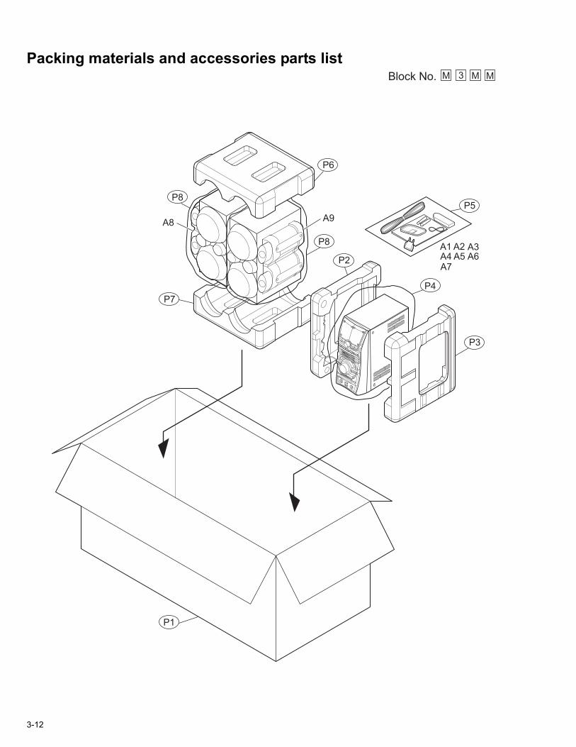
Packing materials and accessories parts list
P6
A1
A9A8
A4 A5 A6A7
A3A2
P5
P2
P8
P7
P1
P4
P3
Block No. M MM3
P8
3-12

Packing and AccessoriesBlock No. [M][3][M][M]
Symbol No. Part No. Part Name Description Local
A 1 AH68-01704C INST BOOK ENG LVT1351-003BA 2 AH59-01539A REMOTE CONTROLA 3 AH39-00320C FM WIREA 4 AH42-00019A ANT LOOPA 5 ------------ BATTERY (x2)A 6 AH39-40001V RCA CABLE
A 7 3721-000117 CONVERSION PLUGA 8 AH81-01691A SPEAKER BOX LA 9 AH81-01691B SPEAKER BOX RP 1 AH69-01408F CARTON FOR SETP 2 AH69-01405A CUSHION L FOR SETP 3 AH69-01406A CUSHION R FOR SETP 4 6902-000068 POLY BAG FOR SETP 5 6902-000385 POLY BAG FOR ACCESSORIESP 6 AH81-01691V CUSHION TOPP 7 AH81-01691W CUSHION BOTTOMP 8 AH81-00631U POLY BAG FOR SPEAKER(x2)
3-13


