Justification for Stage 2 Amendments to R149 (RID ...
9
1 | Page Submitted by GTB SLR-33-11 Justification for Stage 2 Amendments to R149 (RID) (Paragraphs 5.1, 5.2, 5.3 and 5.4) 1. Basic approach The Terms of Reference for Stage 2 Simplification state: • The overarching objective is to update and harmonise the technical requirements for lighting and light- signalling to be suitable for global implementation under the 1958 and 1998 Agreements. • Revise the technical requirements of the new LSD, RID and RRD UN Regulations, to become technology neutral with performance-based and objective test requirements taking into account glare and visibility. Article 1 of the 1958 Agreement (E/ECE/TRANS/505/Rev.3) states: • The Contracting Parties shall establish, through an Administrative Committee made up of all the Contracting Parties in conformity with the rules of procedure set out in the Appendix to this Agreement and on the basis of the following articles, paragraphs, UN Regulations for wheeled vehicles, equipment and parts which can be fitted and/or be used on wheeled vehicles. Conditions for granting type approvals and their reciprocal recognition will be included for use by Contracting Parties which choose to implement Regulations through type approval. Based upon the above, GTB concluded that the amendment of R149 should be developed taking the following factors into account: a) Current UN Regulations are based upon a standardisation approach and each have objective test requirements. They are developed for type approval purposes where each device is type approved individually. b) Some devices are mandatory; others are optional but all require type approval c) A vehicle can be type approved with a combination of devices, each type approved to the pertinent UN regulation d) Devices may be sold individually on the aftermarket if they are listed in the installation regulations and they are type approved to the pertinent requirements in the regulation. This means device specific performance requirements are necessary. e) The proposal shall be suitable for all technologies and consequently it has to maintain the visibility / glare balance that exists today as a minimum legal requirement. It is necessary to define the minimum performance requirements of each of the devices. f) The current test methods (goniometer and measurement of the luminous intensity in the most relevant directions in the forward field) remain the most efficient and cost-effective means of assessment for type approval and production conformity. g) There should be no attempt to start “from zero” to determine the requirements, for minimum illuminance on the road and maximum illuminance on the oncoming drivers’ eyes, to guarantee safe driving. This is dependent upon many factors that need to be researched, such as: atmospheric conditions, road geometry, influences of other traffic, human factors, vehicle condition, system installation tolerances. There is no reliable link between lighting performance and accident rates. The minimum performance requirements should, instead, be based upon a combination of experience of the performance of currently type approved devices and the judgement of experts to determine where more stringent requirements can be introduced. h) There is no common definition for the term “performance-based” and GRE should produce a definition suitable for the particular subject of lighting and light-signalling. This has been explained in SLR-32-18. i) The current and long-established balance between glare and visibility means that, that although improved visibility and reduced glare are a desirable objective there are constraints. There is a balance between glare and visibility that cannot be changed without consequences. Certainly, headlamps are being produced that meet the current photometric requirements and provide increased visibility but they risk more glare complaints even though they meet the current glare photometry requirements. This has been explained in SLR-24-06.
Transcript of Justification for Stage 2 Amendments to R149 (RID ...
1 | P a g e
Submitted by GTB SLR-33-11
Justification for Stage 2 Amendments to R149 (RID)
(Paragraphs 5.1, 5.2, 5.3 and 5.4)
1. Basic approach
The Terms of Reference for Stage 2 Simplification state:
• The overarching objective is to update and harmonise the technical requirements for lighting and light-
signalling to be suitable for global implementation under the 1958 and 1998 Agreements.
• Revise the technical requirements of the new LSD, RID and RRD UN Regulations, to become technology
neutral with performance-based and objective test requirements taking into account glare and visibility.
Article 1 of the 1958 Agreement (E/ECE/TRANS/505/Rev.3) states:
• The Contracting Parties shall establish, through an Administrative Committee made up of all the Contracting
Parties in conformity with the rules of procedure set out in the Appendix to this Agreement and on the basis of
the following articles, paragraphs, UN Regulations for wheeled vehicles, equipment and parts which can be
fitted and/or be used on wheeled vehicles. Conditions for granting type approvals and their reciprocal
recognition will be included for use by Contracting Parties which choose to implement Regulations through type
approval.
Based upon the above, GTB concluded that the amendment of R149 should be developed taking the following factors
into account:
a) Current UN Regulations are based upon a standardisation approach and each have objective test requirements.
They are developed for type approval purposes where each device is type approved individually.
b) Some devices are mandatory; others are optional but all require type approval
c) A vehicle can be type approved with a combination of devices, each type approved to the pertinent UN
regulation
d) Devices may be sold individually on the aftermarket if they are listed in the installation regulations and they
are type approved to the pertinent requirements in the regulation. This means device specific performance
requirements are necessary.
e) The proposal shall be suitable for all technologies and consequently it has to maintain the visibility / glare
balance that exists today as a minimum legal requirement. It is necessary to define the minimum performance
requirements of each of the devices.
f) The current test methods (goniometer and measurement of the luminous intensity in the most relevant
directions in the forward field) remain the most efficient and cost-effective means of assessment for type
approval and production conformity.
g) There should be no attempt to start “from zero” to determine the requirements, for minimum illuminance on
the road and maximum illuminance on the oncoming drivers’ eyes, to guarantee safe driving. This is dependent
upon many factors that need to be researched, such as: atmospheric conditions, road geometry, influences of
other traffic, human factors, vehicle condition, system installation tolerances. There is no reliable link between
lighting performance and accident rates.
The minimum performance requirements should, instead, be based upon a combination of experience of the
performance of currently type approved devices and the judgement of experts to determine where more
stringent requirements can be introduced.
h) There is no common definition for the term “performance-based” and GRE should produce a definition suitable
for the particular subject of lighting and light-signalling. This has been explained in SLR-32-18.
i) The current and long-established balance between glare and visibility means that, that although improved
visibility and reduced glare are a desirable objective there are constraints. There is a balance between glare and
visibility that cannot be changed without consequences. Certainly, headlamps are being produced that meet the
current photometric requirements and provide increased visibility but they risk more glare complaints even
though they meet the current glare photometry requirements. This has been explained in SLR-24-06.
2 | P a g e
j) The CIE Technical Committee 4-45 publication CIE188-2010, CIE Standard S 021 and the SAE J2829
“Pedestrian Visibility - Low Beam Optimization to Reduce Night-time Fatalities” have been used as peer-
reviewed references.
Consequently, this GTB proposal introduces improved photometric performance founded upon the knowledge of experts
from the 19 GTB national delegations taking account of actual design, manufacture and validated performance of current
products.
2. The Stage 2 Proposal for Asymmetrical Passing Beam and AFS
In the current regulation UN R149, there are 7 different asymmetrical passing beams.
o Class A passing beam for low speed vehicles with low performances
o Class B passing beam which is usually convenient for any vehicles of categories M & N
o Class D passing beam which is defined for headlamps with HID light source
o Class C passing beam which is convenient for any driving situation and especially for country roads
o Class E passing beam which is optimized for motorway/ high speed conditions
o Class V passing beam which is optimized for urban area/low speed conditions
o Class W passing beam which is optimized of adverse weather conditions.
o Classes C, E, V, W come from the current UN R123 regulation and can be activated in different driving
configurations.
The purpose of the proposal is to
a) remove the passing beam of class D from the scope as it applies only to gas discharge light sources and, therefore,
is not technologically neutral
b) to merge the relevant requirements of Class B, Class C and class D passing beams. Each of these classes of
passing beam has its own specific requirement even though they are used in similar conditions.
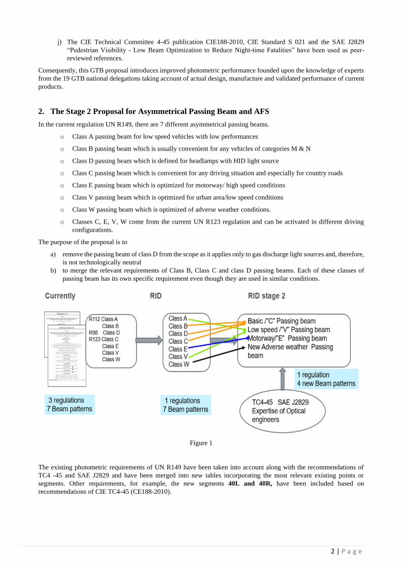
Figure 1
The existing photometric requirements of UN R149 have been taken into account along with the recommendations of
TC4 -45 and SAE J2829 and have been merged into new tables incorporating the most relevant existing points or
segments. Other requirements, for example, the new segments 40L and 40R, have been included based on
recommendations of CIE TC4-45 (CE188-2010).
3 | P a g e
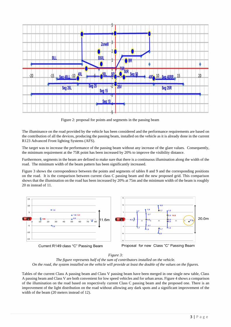
Figure 2: proposal for points and segments in the passing beam
The illuminance on the road provided by the vehicle has been considered and the performance requirements are based on
the contribution of all the devices, producing the passing beam, installed on the vehicle as it is already done in the current
R123 Advanced Front lighting Systems (AFS).
The target was to increase the performance of the passing beam without any increase of the glare values. Consequently,
the minimum requirement at the 75R point has been increased by 20% to improve the visibility distance.
Furthermore, segments in the beam are defined to make sure that there is a continuous illumination along the width of the
road. The minimum width of the beam pattern has been significantly increased.
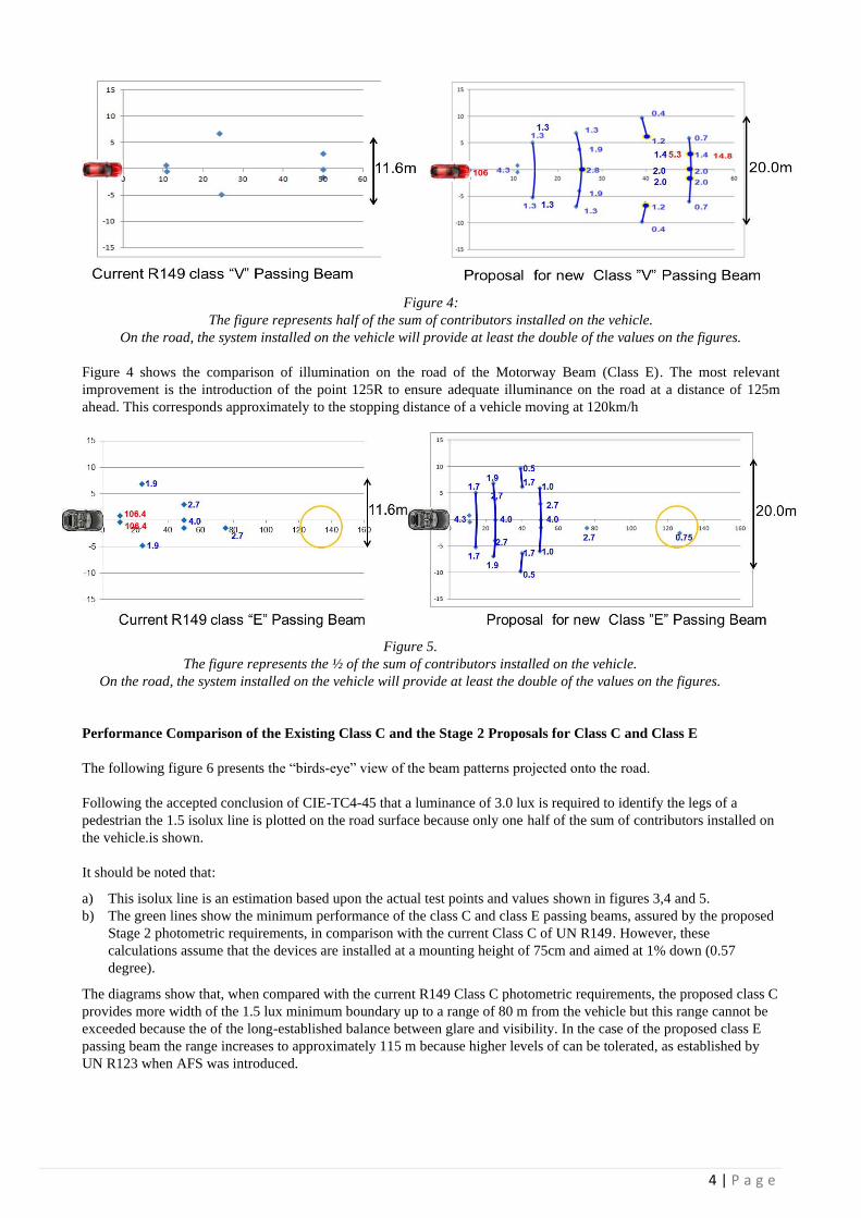
Figure 3 shows the correspondence between the points and segments of tables 8 and 9 and the corresponding positions
on the road. It is the comparison between current class C passing beam and the new proposed grid. This comparison
shows that the illumination on the road has been increased by 20% at 75m and the minimum width of the beam is roughly
20 m instead of 11.
Figure 3:
The figure represents half of the sum of contributors installed on the vehicle.
On the road, the system installed on the vehicle will provide at least the double of the values on the figures.
Tables of the current Class A passing beam and Class V passing beam have been merged in one single new table, Class
A passing beam and Class V are both convenient for low speed vehicles and for urban areas. Figure 4 shows a comparison
of the illumination on the road based on respectively current Class C passing beam and the proposed one. There is an
improvement of the light distribution on the road without allowing any dark spots and a significant improvement of the
width of the beam (20 meters instead of 12).
4 | P a g e
Figure 4:
The figure represents half of the sum of contributors installed on the vehicle.
On the road, the system installed on the vehicle will provide at least the double of the values on the figures.
Figure 4 shows the comparison of illumination on the road of the Motorway Beam (Class E). The most relevant
improvement is the introduction of the point 125R to ensure adequate illuminance on the road at a distance of 125m
ahead. This corresponds approximately to the stopping distance of a vehicle moving at 120km/h
Figure 5.
The figure represents the ½ of the sum of contributors installed on the vehicle.
On the road, the system installed on the vehicle will provide at least the double of the values on the figures.
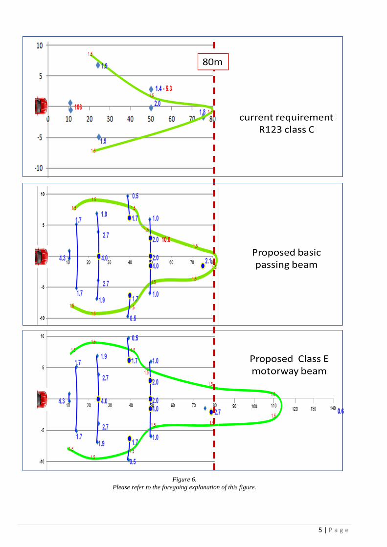
Performance Comparison of the Existing Class C and the Stage 2 Proposals for Class C and Class E
The following figure 6 presents the “birds-eye” view of the beam patterns projected onto the road.
Following the accepted conclusion of CIE-TC4-45 that a luminance of 3.0 lux is required to identify the legs of a
pedestrian the 1.5 isolux line is plotted on the road surface because only one half of the sum of contributors installed on
the vehicle.is shown.
It should be noted that:
a) This isolux line is an estimation based upon the actual test points and values shown in figures 3,4 and 5.
b) The green lines show the minimum performance of the class C and class E passing beams, assured by the proposed
Stage 2 photometric requirements, in comparison with the current Class C of UN R149. However, these
calculations assume that the devices are installed at a mounting height of 75cm and aimed at 1% down (0.57
degree).
The diagrams show that, when compared with the current R149 Class C photometric requirements, the proposed class C
provides more width of the 1.5 lux minimum boundary up to a range of 80 m from the vehicle but this range cannot be
exceeded because the of the long-established balance between glare and visibility. In the case of the proposed class E
passing beam the range increases to approximately 115 m because higher levels of can be tolerated, as established by
UN R123 when AFS was introduced.
5 | P a g e
Figure 6.
Please refer to the foregoing explanation of this figure.
6 | P a g e
3. The Stage 2 Proposal for Symmetrical Passing Beam
In UN R149 there are 5 different symmetrical passing beams.
• Class AS & BS passing beam for mopeds (UN Regulation No. 74)
• Class CS Passing beam used for light motorcycles (≤ 125 cc)
• Class DS passing beam used for motorcycles (> 125 cc)
• Class ES passing beam with light sources exceeding 2000 lm.
The concept of the proposal is:
• The foundation of the beam pattern is taken from UN R113 (not from UN Regulation No. 123), since it is
currently accepted as the best compromise between road illumination and other performance requirements for
motorcycles (it is worth noting that this proposal is compatible with FMVSS108 “Table XX - motorcycle lower
beam requirements” in the same way as for the current UN R113).
• To ensure homogeneous illumination, as alternative to the minimum luminous flux requirement, ‘segments’
are introduced into the proposed beam pattern.
• As for illumination areas newly set in basic passing-beam pattern reflecting CIE outcome, they are also
incorporated into the proposal with adaptation for photometry points based on UN R113.
Classes AS and BS have been kept unchanged, considering their significantly limited application and market, as they may
only be used for mopeds.
Classes CS and DS have been improved, in line with the concept of the asymmetrical passing beam.
Classes DS and ES have been merged, as Class ES was intended only to apply for headlamps equipped with light source
with flux greater than 2,000 lm. This criterion is not performance oriented.
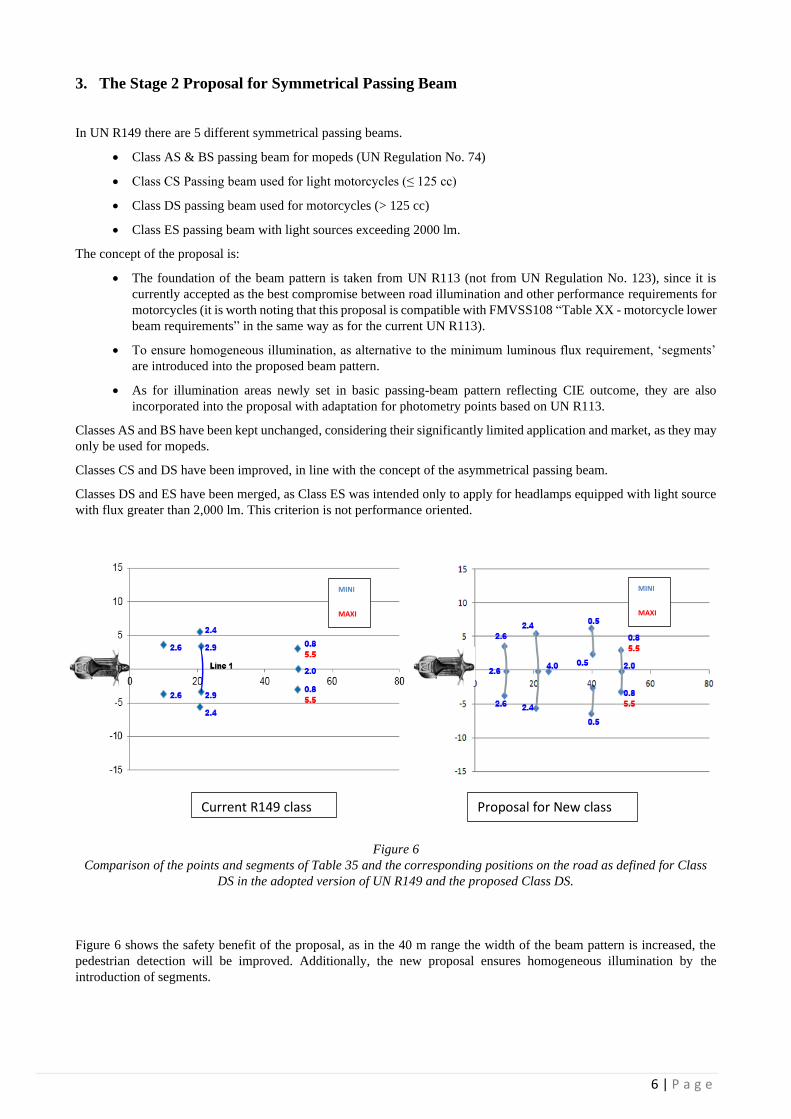
Figure 6
Comparison of the points and segments of Table 35 and the corresponding positions on the road as defined for Class
DS in the adopted version of UN R149 and the proposed Class DS.
Figure 6 shows the safety benefit of the proposal, as in the 40 m range the width of the beam pattern is increased, the
pedestrian detection will be improved. Additionally, the new proposal ensures homogeneous illumination by the
introduction of segments.
Proposal for New class
DS
Current R149 class
DS
MINI
MAXI
MINI
MAXI
7 | P a g e
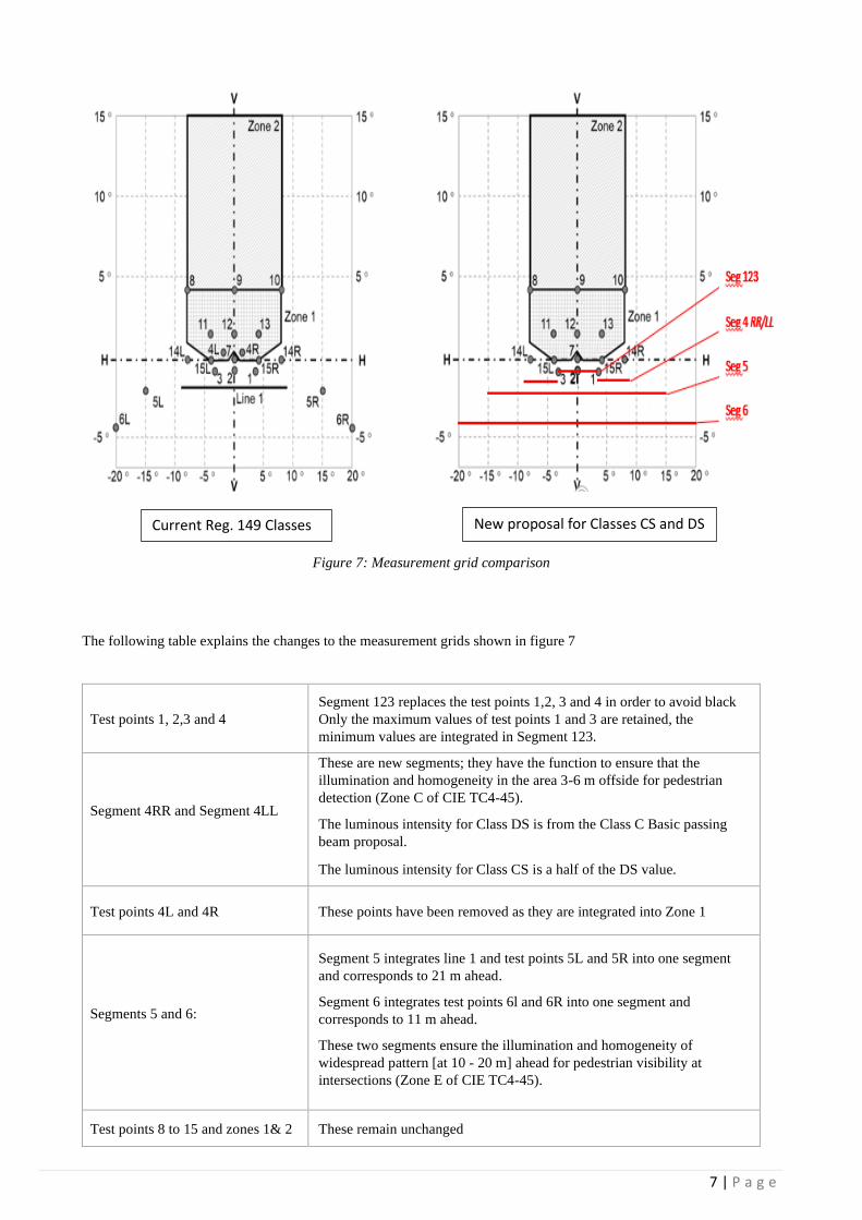
Figure 7: Measurement grid comparison
The following table explains the changes to the measurement grids shown in figure 7
Test points 1, 2,3 and 4
Segment 123 replaces the test points 1,2, 3 and 4 in order to avoid black
Only the maximum values of test points 1 and 3 are retained, the
minimum values are integrated in Segment 123.
Segment 4RR and Segment 4LL
These are new segments; they have the function to ensure that the
illumination and homogeneity in the area 3-6 m offside for pedestrian
detection (Zone C of CIE TC4-45).
• The luminous intensity for Class DS is from the Class C Basic passing
beam proposal.
• The luminous intensity for Class CS is a half of the DS value.
Test points 4L and 4R These points have been removed as they are integrated into Zone 1
Segments 5 and 6:
Segment 5 integrates line 1 and test points 5L and 5R into one segment
and corresponds to 21 m ahead.
Segment 6 integrates test points 6l and 6R into one segment and
corresponds to 11 m ahead.
These two segments ensure the illumination and homogeneity of
widespread pattern [at 10 - 20 m] ahead for pedestrian visibility at
intersections (Zone E of CIE TC4-45).
Test points 8 to 15 and zones 1& 2 These remain unchanged
Current Reg. 149 Classes
CS DS and ES
New proposal for Classes CS and DS
8 | P a g e
4. The Stage 2 Proposal for Driving Beam
According to R48 par.2.7.9., the driving beam is defined as "Driving beam (main-beam) headlamp" means the lamp used
to illuminate the road over a long distance ahead of the vehicle;”
Notwithstanding this brief and simple definition, in the content of the various regulations many different classes of driving
beams, depending on the vehicle category, the light source used, etc., have been introduced.
In order to simplify UN R149 and to retain the existing minimum safety requirements, while considering performance
measurability and technological neutrality, some beam classes and requirements have been combined and updated by this
proposal. To satisfy the goal of technological neutrality, the performance of the vehicle is considered to be a more
appropriate criterion for the beam classification instead of the light source technology.
Especially in view of the significant technological progress in the field of automotive light sources, in terms of their
efficiency and durability improvement, as well as increased traffic speed and density, some of the minimum intensity
requirements have been increased.
Following the approach adopted in UN R123, of treating lighting as a “system”, minimum requirements for the sum of
the luminous intensities of the devices mounted on the left and right hand of the vehicle are introduced.
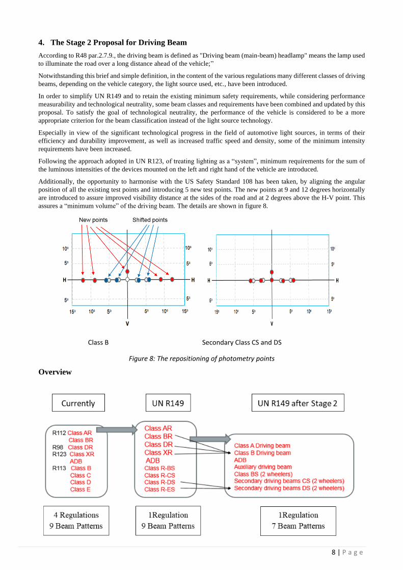
Additionally, the opportunity to harmonise with the US Safety Standard 108 has been taken, by aligning the angular
position of all the existing test points and introducing 5 new test points. The new points at 9 and 12 degrees horizontally
are introduced to assure improved visibility distance at the sides of the road and at 2 degrees above the H-V point. This
assures a “minimum volume” of the driving beam. The details are shown in figure 8.
Figure 8: The repositioning of photometry points
Overview
Class B Secondary Class CS and DS
9 | P a g e
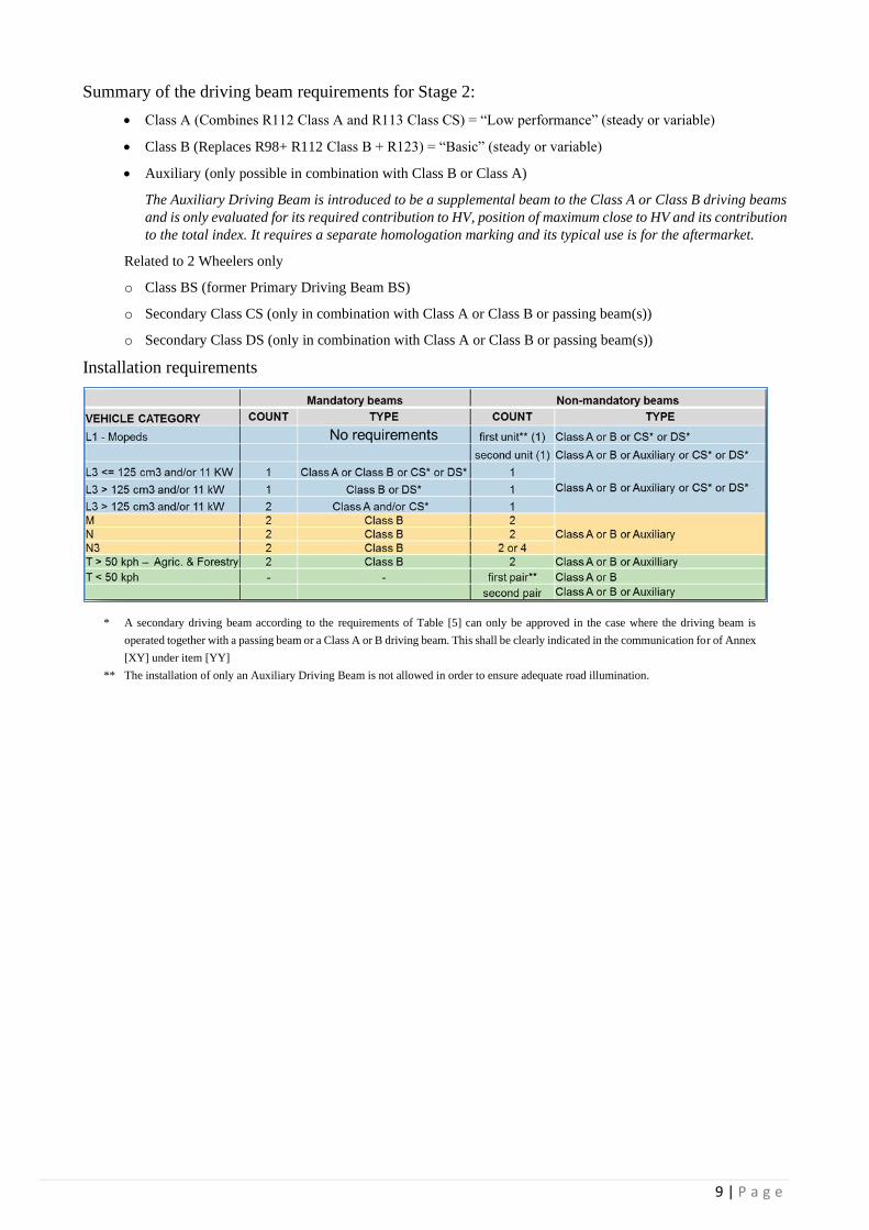
Summary of the driving beam requirements for Stage 2:
• Class A (Combines R112 Class A and R113 Class CS) = “Low performance” (steady or variable)
• Class B (Replaces R98+ R112 Class B + R123) = “Basic” (steady or variable)
• Auxiliary (only possible in combination with Class B or Class A)
The Auxiliary Driving Beam is introduced to be a supplemental beam to the Class A or Class B driving beams
and is only evaluated for its required contribution to HV, position of maximum close to HV and its contribution
to the total index. It requires a separate homologation marking and its typical use is for the aftermarket.
Related to 2 Wheelers only
o Class BS (former Primary Driving Beam BS)
o Secondary Class CS (only in combination with Class A or Class B or passing beam(s))
o Secondary Class DS (only in combination with Class A or Class B or passing beam(s))
Installation requirements
* A secondary driving beam according to the requirements of Table [5] can only be approved in the case where the driving beam is
operated together with a passing beam or a Class A or B driving beam. This shall be clearly indicated in the communication for of Annex
[XY] under item [YY]
** The installation of only an Auxiliary Driving Beam is not allowed in order to ensure adequate road illumination.