
Jurnal Fisika
11
Evidence for subwavelength imaging with positive refraction This article has been downloaded from IOPscience. Please scroll down to see the full text article. 2011 New J. Phys. 13 033016 (http://iopscience.iop.org/1367-2630/13/3/033016) Download details: IP Address: 203.130.244.204 The article was downloaded on 20/02/2012 at 04:50 Please note that terms and conditions apply. View the table of contents for this issue, or go to the journal homepage for more Home Search Collections Journals About Contact us My IOPscience
-
Upload
findi-diansari -
Category
Documents
-
view
57 -
download
2
description
Sebuah jurnal yang membahas fenomena fisika
Transcript of Jurnal Fisika

Evidence for subwavelength imaging with positive refraction
This article has been downloaded from IOPscience. Please scroll down to see the full text article.
2011 New J. Phys. 13 033016
(http://iopscience.iop.org/1367-2630/13/3/033016)
Download details:
IP Address: 203.130.244.204
The article was downloaded on 20/02/2012 at 04:50
Please note that terms and conditions apply.
View the table of contents for this issue, or go to the journal homepage for more
Home Search Collections Journals About Contact us My IOPscience

T h e o p e n – a c c e s s j o u r n a l f o r p h y s i c s
New Journal of Physics
Evidence for subwavelength imaging withpositive refraction
Yun Gui Ma1, Sahar Sahebdivan2, C K Ong3, Tomás Tyc2,4
and Ulf Leonhardt2,5
1 Temasek Laboratories, National University of Singapore,Singapore 119260, Singapore2 School of Physics and Astronomy, University of St Andrews, North Haugh,St Andrews KY16 9SS, UK3 Centre for Superconducting and Magnetic Materials, Department of Physics,National University of Singapore, Singapore 117542, Singapore4 Faculty of Science, Kotlarska 2 and Faculty of Informatics, Botanicka 68a,Masaryk University, 61137 Brno, Czech RepublicE-mail: [email protected]
New Journal of Physics 13 (2011) 033016 (10pp)Received 4 December 2010Published 9 March 2011Online at http://www.njp.org/doi:10.1088/1367-2630/13/3/033016
Abstract. The resolution of lenses is normally limited by the wave nature oflight. Imaging with perfect resolution was believed to rely on negative refraction,but here we present experimental evidence for subwavelength imaging withpositive refraction.
Ordinary lenses cannot resolve details finer than about half the wavelength of light [1]. Perfectlenses made of negatively refracting metamaterials were predicted [2] to image with unlimitedresolution. In practice, however, passive negatively refracting materials have the disadvantageof being inherently dissipative [3]. Subwavelength details are dissipated away; only ‘poor-man’s perfect lenses’ have worked [4]—they image over distances of merely a small fraction ofthe wavelength. Hyperlenses [5, 6] created magnified virtual images with a resolution limitedby their geometric extensions. Time-reversed mirrors [7] made subwavelength images forelectromagnetic microwaves, but with active devices that are difficult to implement for visiblelight.
Maxwell [8] showed that a lens with a particular spatial distribution of refractiveindex, ‘Maxwell’s fish eye’, would, if analyzed by ray optics, give perfect resolution, i.e. apoint source would give a point image. Ray optics ignores the wave nature of light and it
5 Author to whom any correspondence should be addressed.
New Journal of Physics 13 (2011) 0330161367-2630/11/033016+10$33.00 © IOP Publishing Ltd and Deutsche Physikalische Gesellschaft

2
Figure 1. Focusing in curved space. In Maxwell’s fish eye, electromagneticwaves propagate in a plane in physical space (wave pattern below) as if theywere confined to the surface of a sphere (above). A wave emitted from any pointon the virtual sphere is focused at the antipodal point. In physical space, wavesare as perfectly focused as in virtual space.
was assumed that in reality the resolution would again be about half the wavelength. Wepredicted that this is not so [9, 10]: Maxwell’s fish eye should image waves with perfectresolution [11], which contradicted the accepted wisdom of subwavelength imaging [2] andcreated controversy [12]–[22]. Here, we present experimental evidence for subwavelengthimaging over superwavelength distances in Maxwell’s fish eye using microwaves. Like light,microwaves are electromagnetic waves, but with cm wavelenghts and GHz frequencies, whichallow us to investigate the electromagnetic fields with a degree of detail currently impossiblefor visible light. Our microwave experiments establish the principle and encourage extensionsto visible and shorter wavelengths [23, 24], and to other waves [11], such as sound.
Our experiments are inspired by the idea that optical materials change the geometryperceived by light [25], which can be represented by a spatial mapping [26]–[29]: lightpropagation in physical space corresponds to propagation in a transformed virtual space. Forexample, a negatively refracting perfect lens folds space [30]: in virtual space, a plane ofphysical space appears like a folded sheet of paper [25]. The electromagnetic fields in the foldedregions are identical; they are ‘carbon copies’ of each other, which explains in a geometricalpicture why negative refraction makes a perfect lens. In this case, the underlying geometryis Euclidean, because the coordinate transformation from physical to virtual space does notintroduce intrinsic curvature [25]. In contrast, in our case (figure 1), the virtual space is curved:electromagnetic waves propagating in a plane with the refractive-index profile of Maxwell’s fisheye behave as if they were confined to the surface of a virtual sphere [31], a curved space withnon-Euclidean geometry [32].
To understand why Maxwell’s fish eye can make perfect images, imagine light confined tothe curved geometry of the sphere [33] (figure 1). Any source can be regarded as a collection
New Journal of Physics 13 (2011) 033016 (http://www.njp.org/)

3
of point sources, so it suffices to investigate the wave produced by a single point source ofarbitrary position on the sphere. A wave propagates from the point of emission round the sphereand focuses at the antipodal point; this corresponds to emission from a point in the plane ofthe actual device and focusing at another point. The wave propagating round the virtual spherewould come to the image point and then continue to travel back to the source. At the image itonly turns into an exact inward-going wave if it is extracted at the image point [34, 35]. For this,one could employ an active drain synchronized with the time of arrival at the image, as in thedemonstration of subwavelength imaging using far-field time reversal [35], but our experimentsshow that a completely passive outlet has the same effect: the outlet naturally extracts theelectromagnetic wave as if it were a source run in reverse; a point source thus appears as a pointimage. Of course, the outlet must be at the correct image point, which is natural in imaging: forexample, in a charged-coupled device (CCD) array only the detector at the correct point shouldfire. An array of outlets plays the role of a detector array or of the photosensitive molecules ina photographic substance. Our experiments show that, given a choice of outlets, i.e. a choice ofdetectors, the wave naturally focuses at the correct image positions6.
Note that Maxwell’s fish eye is an unusual ‘lens’ where both the source and the image areinside it, but in other proposals for perfect imaging with positive refraction [37], the source andthe image can be in empty space (and in three dimensions (3D)). It may also be possible tomake magnifying perfect lenses [38]. Essential for perfect imaging seems to be the feature thatall rays from the source focus at the image, which is possible in a curved optical geometry [32],whereas in ordinary lenses only forward-propagating waves are imaged.
We have implemented Maxwell’s fish eye for microwave radiation confined between twoparallel metal plates constituting a planar waveguide [39]. Our device (figure 2) is insertedbetween the plates; its profile of refractive index n lets microwaves in the plane behave as if theywere propagating on the surface of a half-sphere. The device is surrounded by a metal mirrorsuch that the waves together with their mirror image correspond to waves on the complete virtualsphere (figure 1) of Maxwell’s fish eye [9]. Our device is made of concentric layers of coppercircuit board with etched-out structures that shape its electromagnetic properties (together withadditional filling material). It resembles a microwave cloaking device [40] or a transmuted Eatonlens [41] (except that the fish-eye structures respond to the electric and not the magnetic field).Our structures are designed [41, 42] for non-resonant operation such that the device can performperfect imaging over a broad band of the spectrum. The device has a radius of 5 cm, a thicknessof 5 mm and fits exactly between the metal plates of the waveguide. The plate separation ischosen such that only microwaves with an electric field perpendicular to the plates can travelinside, because only for electromagnetic waves of this polarization does a material with electricpermittivity ε = n2 appear to curve space perfectly [9, 25].
As sources, we employ coaxial cables inserted through the bottom plate. The cables havean outer diameter of 2.1 mm, 1.68 mm teflon isolator and 0.5 mm inner conductor; the latteris exposed by 4.5 mm in the device for creating an approximate line source. Through thesource cables, we inject microwave radiation of free-space wavelength λ0 = 3 cm generatedby a vector network analyzer (HP 8722D) that doubles as a synthesizer and an analyzer. The
6 In the Feynman lectures [36], when discussing outward- and inward-going spherical waves, the reader isreminded that Maxwell’s equations are time reversible. Consequently, an electromagnetic wave can be as perfectlyfocused at a point as it can be created by a point source [34], provided that the wave is time reversed and thendetected at the image by a time-reversed source, a drain. We show here that both the effect of the time reversal andthe field localization can be achieved with completely passive materials and without prior knowledge of the field.
New Journal of Physics 13 (2011) 033016 (http://www.njp.org/)
4
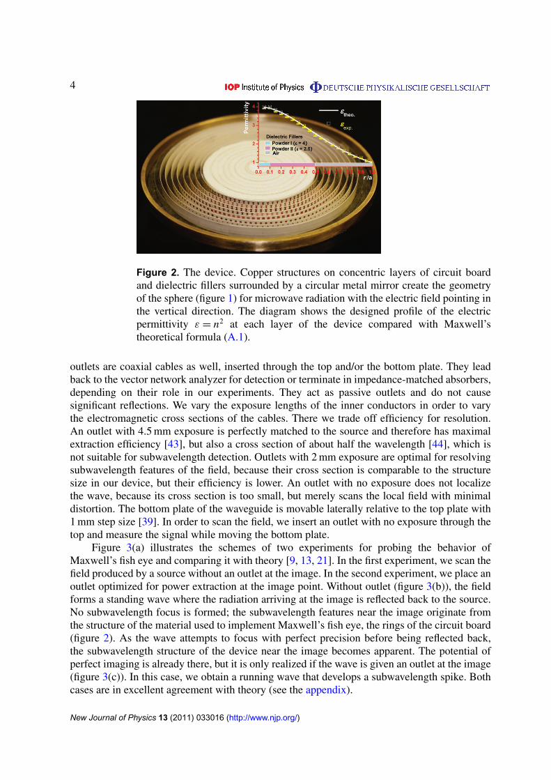
Figure 2. The device. Copper structures on concentric layers of circuit boardand dielectric fillers surrounded by a circular metal mirror create the geometryof the sphere (figure 1) for microwave radiation with the electric field pointing inthe vertical direction. The diagram shows the designed profile of the electricpermittivity ε = n2 at each layer of the device compared with Maxwell’stheoretical formula (A.1).
outlets are coaxial cables as well, inserted through the top and/or the bottom plate. They leadback to the vector network analyzer for detection or terminate in impedance-matched absorbers,depending on their role in our experiments. They act as passive outlets and do not causesignificant reflections. We vary the exposure lengths of the inner conductors in order to varythe electromagnetic cross sections of the cables. There we trade off efficiency for resolution.An outlet with 4.5 mm exposure is perfectly matched to the source and therefore has maximalextraction efficiency [43], but also a cross section of about half the wavelength [44], which isnot suitable for subwavelength detection. Outlets with 2 mm exposure are optimal for resolvingsubwavelength features of the field, because their cross section is comparable to the structuresize in our device, but their efficiency is lower. An outlet with no exposure does not localizethe wave, because its cross section is too small, but merely scans the local field with minimaldistortion. The bottom plate of the waveguide is movable laterally relative to the top plate with1 mm step size [39]. In order to scan the field, we insert an outlet with no exposure through thetop and measure the signal while moving the bottom plate.
Figure 3(a) illustrates the schemes of two experiments for probing the behavior ofMaxwell’s fish eye and comparing it with theory [9, 13, 21]. In the first experiment, we scan thefield produced by a source without an outlet at the image. In the second experiment, we place anoutlet optimized for power extraction at the image point. Without outlet (figure 3(b)), the fieldforms a standing wave where the radiation arriving at the image is reflected back to the source.No subwavelength focus is formed; the subwavelength features near the image originate fromthe structure of the material used to implement Maxwell’s fish eye, the rings of the circuit board(figure 2). As the wave attempts to focus with perfect precision before being reflected back,the subwavelength structure of the device near the image becomes apparent. The potential ofperfect imaging is already there, but it is only realized if the wave is given an outlet at the image(figure 3(c)). In this case, we obtain a running wave that develops a subwavelength spike. Bothcases are in excellent agreement with theory (see the appendix).
New Journal of Physics 13 (2011) 033016 (http://www.njp.org/)

5
Figure 3. Field pattern. (a) Scheme of two imaging experiments of a point sourcewithout the outlet (b) and with the outlet (c) at the image point; λ0 indicates thefree-space wavelength of 3 cm. The field intensity is scanned. Without the outlet,no subwavelength focus is formed, whereas with the outlet, a sharp spike appearsat the image.
The acid test for imaging is the resolution between two point sources. In a third experiment,we thus insert two source cables with 0.2λ distance from each other where λ denotes the localwavelength λ0/n. In ordinary imaging [1], the two sources would not be resolvable. We capturethe image with an array of ten outlets of 2 mm exposure that are inserted in the bottom platein an arc with 0.05λ spacing between them; they represent a detector array. Two of the outletsare at the correct image points, but the others are not; for perfect imaging, only the detectorsat the correct points should fire. We do not directly monitor the field intensity extracted bythe outlets; their cables terminate in absorbers, because it is experimentally easier to scan thefield localized at the outlets. As the intensity at the outlets is proportional to the extracted fieldintensity, this procedure gives the intensity profile recorded by a detector array. For scanningthe field at the image, we insert another outlet of the same type (2 mm exposure) through thetop plate (for scanning the field at the source we use outlets with no exposure). The scanningoutlet is connected to the vector network analyzer for measuring the throughput. We move thetop outlet in discrete steps along the arc and record the intensity. Figure 4 shows that the fieldlocalizes on its own near the outlets at the correct image positions. The localization is not anartifact of the outlets, in contrast to what was claimed in the controversy about perfect imagingwith positive refraction [12], [14]–[16], [19, 20], because otherwise all outlets within a spot ofλ/2 would enhance the field intensity. The two subwavelength sources are clearly resolved inthe image, which unambiguously proves subwavelength imaging with positive refraction.
We have thus proved by experiment that the imaging resolution in Maxwell’s fish eye isno longer limited by the wave nature of electromagnetic radiation, but rather by the structureof the material7, which in our case is approximately 0.1λ. With unstructured materials—notmetamaterials—such as graded-index materials or tapered waveguides [23, 45], the imagingresolution can in principle be made perfect.
Acknowledgments
YGM and CKO are supported by DSO National Laboratories and the Defence Research andTechnology Office (DRTech) of Singapore. TT acknowledges support through the grants MSM0021622409 and MSM 0021622419. UL is supported by a Royal Society Wolfson ResearchMerit Award and a Theo Murphy Blue Skies Award of the Royal Society.
7 We used a structured metamaterial because it was cheap to make.
New Journal of Physics 13 (2011) 033016 (http://www.njp.org/)

6
Figure 4. Imaging. Source: two sources (red dots) are placed 0.2λ apart whereλ is the local wavelength; their scanned field is shown. Image: an array of tenoutlets (red dots) are arranged in an arc in the bottom plate; they act like adetector array. A single outlet (blue dot) inserted through the top plate is movedalong the arc over the image outlets and records the intensity. The picture showsthe measured intensity normalized with respect to the maximal intensity. The reddots indicate the positions where outlets are present. This detector array clearlyresolves the two sources, which proves subwavelength imaging.
Appendix. Theory and experiment
In this appendix, we compare theory with experiment. Let us briefly summarize thetheory [9, 13, 21]. For simplicity, we describe the Cartesian coordinates x and y in the plane ofthe waveguide in units of the device radius a. It is convenient to combine the two coordinates inone complex number z = x + iy. In this notation and with our units, the refractive-index profileof Maxwell’s fish eye reads [8, 9]
n =2
1 + |z|2. (A.1)
Consider stationary electromagnetic waves with wavenumber k (in our units) and electric fieldpolarized in the vertical direction. In this case, the electric field strength is characterized by onlyone scalar complex Fourier amplitude E that varies in the z-plane; we denote it by E(z). Weassume that the wave propagates inside a material with electric permittivity ε = n2 and indexprofile (A.1) surrounded by a perfect mirror at r = 1. Theory [13, 21] shows that the field of a
New Journal of Physics 13 (2011) 033016 (http://www.njp.org/)

7
Figure A1. Comparison with theory for radiation without outlet. The fieldamplitude scanned along the line between the source and the outlet is comparedwith the analytical formula (A.2). The figure shows a standing wave in very goodagreement with theory; the subwavelength features near the image originate fromthe structures of the material used to implement the fish eye mirror; the deviationnear the source is due to its imperfection.
perfect line source without outlet at the image is given by the exact expressions
E(z) = G(z) − G(1/z∗), G =Pν(ζ )
4 sin(νπ), (A.2)
where Pν are Legendre functions [46] with the index
ν =12
(√4k2 + 1 − 1
). (A.3)
For the variable ζ of the Legendre functions, we have [9]
ζ =|z′
|2− 1
|z′|2 + 1, z′
=z − z0
z∗
0z + 1, (A.4)
where z0 denotes the coordinates x0 and y0 of the line source in complex representationz0 = x0 + iy0. The wave function (A.2) develops a logarithmic singularity at the source pointthat appears as the sharp peak in the measured intensity (figure 3(b)). The electromagneticfield forms a standing wave [13] with real wave function (A.2), where the radiation bouncesback and forth in the device. In our experiments, we are able to measure both the real andthe imaginary part of the oscillating electromagnetic wave—they correspond to the in-phaseand out-of-phase components of the scanned field. For this, the scanning cable is fed into the
New Journal of Physics 13 (2011) 033016 (http://www.njp.org/)

8
Figure A2. Comparison with theory for the wave with the outlet. The fieldamplitude scanned along the line between the source and the outlet is comparedwith the analytical formula (A.5). The figure shows a running wave with complexwave function in good agreement with theory; the sharp spike of Re(E) is anearly perfect image of the source.
vector network analyzer where the signal is measured and decomposed into in-phase and out-of-phase components with respect to the synthesized field. Figure A.1 compares the results ofour measurements with our analytical formulae: theory and experiment agree very well, exceptnear the source where its finite cross section becomes apparent; we do not have an ideal linesource. Our measurements confirm that without outlet, the wave is real and so a standing waveis formed, which cannot create a perfect image [13]. One sees that instead of a sharp spike, adiffraction-limited spot appears.
All it takes to form a sharp image is an outlet for the radiation. An ideal point detectorplays the role of such an outlet, absorbing radiation at the image point but not elsewhere. Thisdetector will only fire when it is placed at the correct position. In this case, we obtain a runningwave with the wave function [9]
E(z) = G(z) − G(1/z∗), G =Pν(ζ ) − eiνπ Pν(−ζ )
4 sin(νπ)(A.5)
and expressions (A.3) and (A.4). The wave function (A.5) develops two logarithmicsingularities [9] within the region |z| < 1 of the device, one at the source z0 and one at theimage point
z′
0 = −z0. (A.6)
This means that the wave forms an exact image with a resolution not limited by the wave natureof light. The singularity at the image turns out [9] to carry the phase factor exp(iπν), so the
New Journal of Physics 13 (2011) 033016 (http://www.njp.org/)

9
phase delay is πν. Figure A.2 shows that formula (A.5) agrees well with our data, apart fromimperfections due to the finite electromagnetic cross section of the source and the image. Thedeviations are particularly strong in the imaginary part of the Fourier amplitude for reasons wedo not fully understand yet. One sees that the field forms a running wave with a complex wavefunction. The wave disappears through the outlet at the focal point in a perfect image. Only thedetected field is imaged with point-like precision, but detection is the very point of imaging.
References
[1] Abbe E 1873 Arch. Mikrosk. Anat. 9 413[2] Pendry J B 2000 Phys. Rev. Lett. 85 3966[3] Stockman M I 2007 Phys. Rev. Lett. 98 177404[4] Fang N, Lee H, Sun C and Zhang X 2005 Science 308 534[5] Jacob Z, Alekseyev L V and Narimanov E 2006 Opt. Express 14 8247[6] Liu Z, Lee H, Xiong Y, Sun C and Zhang X 2007 Science 315 1686[7] Lerosey G, de Rosny J, Tourin A and Fink M 2007 Science 315 1120[8] Maxwell J C 1854 Camb. Dublin Math. J. 8 188[9] Leonhardt U 2009 New J. Phys. 11 093040
[10] Leonhardt U and Philbin T G 2010 Phys. Rev. A 81 011804[11] Benitez P, Miñano J C and González J C 2010 Opt. Express 18 7650[12] Blaikie R J 2010 New J. Phys. 12 058001[13] Leonhardt U 2010 New J. Phys. 12 058002[14] Guenneau S, Diatta A and McPhedran R C 2010 J. Mod. Opt. 57 511[15] Sun F and He S 2010 Prog. Electromagn. Res. 108 307[16] Merlin R 2010 Phys. Rev. A 82 057801[17] Leonhardt U and Philbin T G 2010 Phys. Rev. A 82 057802[18] Leonhardt U and Sahebdivan S 2011 J. Opt. 13 024016[19] Merlin R 2011 J. Opt. 13 024017[20] Kinsler P and Favaro A 2011 New J. Phys. 13 028001[21] Leonhardt U 2011 New J. Phys. 13 028002[22] González J C, Benitez P and Miñano J C 2011 New J. Phys. 13 023038[23] Smolyaninova V N, Smolyaninov I I, Kildishev A V and Shalaev V M 2010 Opt. Lett. 35 3396[24] Gabrielli L H, Leonhardt U and Lipson M 2010 arXiv:1007.2564[25] Leonhardt U and Philbin T G 2010 Geometry and Light: The Science of Invisibility (New York: Dover)[26] Leonhardt U 2006 Science 312 1777[27] Pendry J B, Schurig D and Smith D R 2006 Science 312 1780[28] Shalaev V M 2008 Science 322 384[29] Chen H, Chan C T and Sheng P 2010 Nat. Mater. 9 387[30] Leonhardt U and Philbin T G 2006 New J. Phys. 8 247[31] Luneburg R K 1964 Mathematical Theory of Optics (Berkeley, CA: University of California Press)[32] Leonhardt U and Tyc T 2009 Science 323 110[33] Schultheiss V H, Batz S, Szameit A, Dreisow F, Nolte S, Tünnermann A, Longhi S and Peschel U 2010 Phys.
Rev. Lett. 105 143901[34] Quabis S, Dorn R, Eberler M, Glöckl O and Leuchs G 2000 Opt. Commun. 179 1[35] de Rosny L and Fink M 2002 Phys. Rev. Lett. 89 124301[36] Feynman R P, Leighton R P and Sands M 2006 The Feynman Lectures on Physics vol 2 (San Francisco, CA:
Addison-Wesley)[37] Miñano J C 2006 Opt. Express 14 9627[38] Tyc T and Sarbort M 2010 arXiv:1010.3178
New Journal of Physics 13 (2011) 033016 (http://www.njp.org/)

10
[39] Zhao L, Chen X and Ong C K 2008 Rev. Sci. Instrum. 79 124701[40] Schurig D, Mock J J, Justice B J, Cummer S A, Pendry J B, Starr A F and Smith D R 2006 Science 314 977[41] Ma Y G, Ong C K, Tyc T and Leonhardt U 2009 Nat. Mater. 8 639[42] Smith D R and Pendry J B 2006 J. Opt. Soc. Am. B 23 391[43] Marques R, Freire M J and Baena J D 2006 Appl. Phys. Lett. 89 211113[44] Cornbleet S 1976 Microwave Optics: The Optics of Microwave Antenna Design (London: Academic)[45] Miñano J C, Benitez P and González J C 2010 New J. Phys. 12 123023[46] Erdélyi A, Magnus W, Oberhettinger F and Tricomi F G 1981 Higher Transcendental Functions vol 1
(New York: McGraw-Hill)
New Journal of Physics 13 (2011) 033016 (http://www.njp.org/)