JUNE How to CENTS Correct AD 10 · RADIO WORLD June 18, 1927 B.S.T. DE LUXE A NEW AND IMPROVED...
24
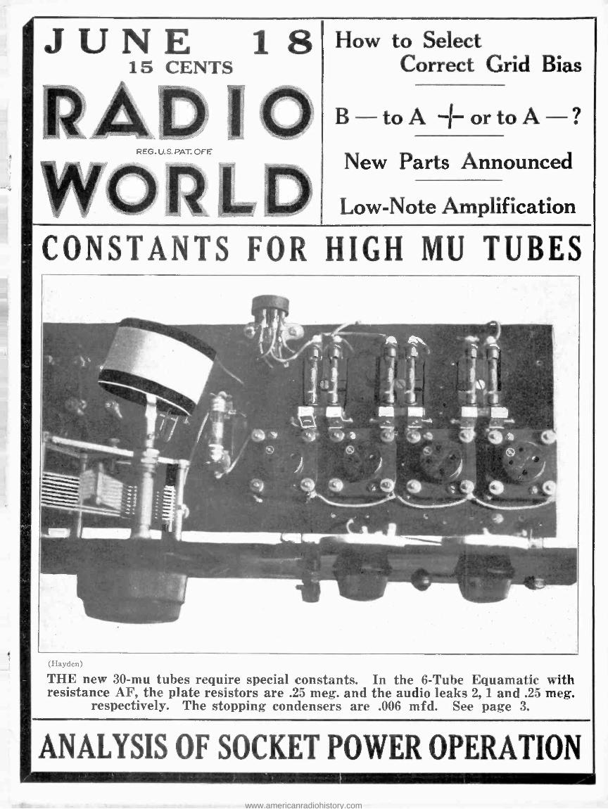
JUNE 1 8 15 CENTS AD 10 REG. U.S. PAT. OFF How to Select Correct Grid Bias B to ±ortoA? New Parts Announced Low -Note Amplification CONSTANTS FOR HIGH MU TUBES 1 411 N "it w a. .a, 416 1 .S i í 161 . _ ... B NRINV-41111611ffir . 4 (Flaydcn) THE new 30 -mu tubes require special constants. In the 6 -Tube Equamatic with resistance AF, the plate resistors are .25 meg. and the audio leaks 2, 1 and .25 meg. respectively. The stopping condensers are .006 mfd. See page 3. ANALYSIS OF SOCKET POWER OPERATION www.americanradiohistory.com
Transcript of JUNE How to CENTS Correct AD 10 · RADIO WORLD June 18, 1927 B.S.T. DE LUXE A NEW AND IMPROVED...
JUNE 1 8 15 CENTS
AD 10 REG. U.S. PAT. OFF
How to Select Correct Grid Bias
B to ±ortoA? New Parts Announced
Low -Note Amplification
CONSTANTS FOR HIGH MU TUBES
1
411 N "it w a.
.a, 416
1
.S i í
161 . _ ...
B
NRINV-41111611ffir . 4
(Flaydcn)
THE new 30 -mu tubes require special constants. In the 6 -Tube Equamatic with resistance AF, the plate resistors are .25 meg. and the audio leaks 2, 1 and .25 meg.
respectively. The stopping condensers are .006 mfd. See page 3.
ANALYSIS OF SOCKET POWER OPERATION
www.americanradiohistory.com
RADIO WORLD June 18, 1927
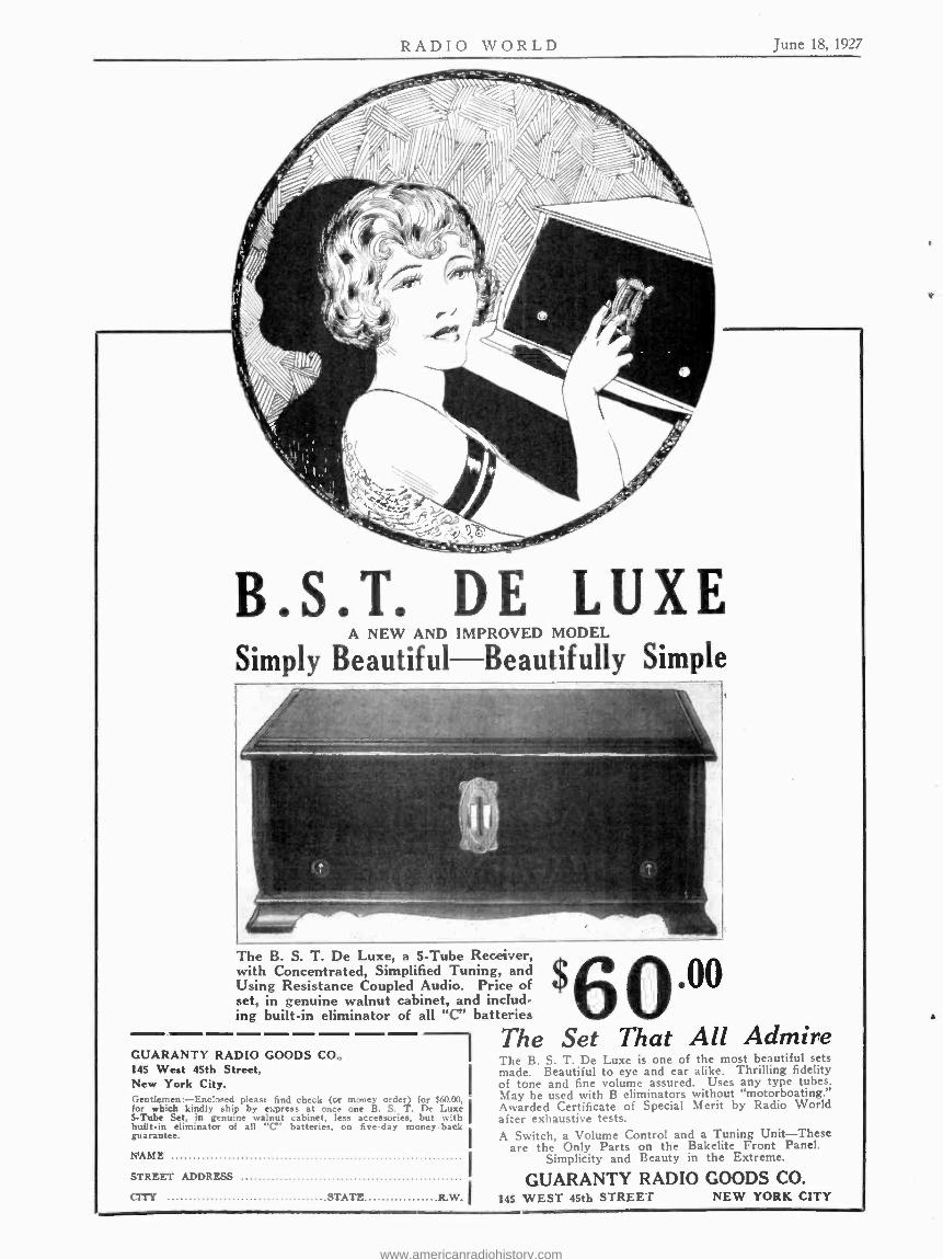
B.S.T. DE LUXE A NEW AND IMPROVED MODEL
Simply Beautiful Beautifully Simple
The B. S. T. De Luxe, a 5 -Tube Receiver, with Concentrated, Simplified Tuning, and Using Resistance Coupled Audio. Price of set, in genuine walnut cabinet, and includ- ing built -in eliminator of all "C" batteries
The Set That All Admire $6
GUARANTY RADIO GOODS CO., 145 West 45th Street, New York City. Gentlemen:- Enclosed please find check (or money order) for $60.00, for which kindly ship by express at once one B. S. T. De Luxe I S-Tube Set, in genuine walnut cabinet, less accessories, but with built -in eliminator of all "C" batteries, on five -day money -back guarantee.
NAME
STREET ADDRESS
CITY STATE R.W.I
The B. S. T. De Luxe is one of the most beautiful sets made. Beautiful to eye and ear alike. Thrilling fidelity of tone and fine volume assured. Uses any type tubes. May be used with B eliminators without "motorboating." Awarded Certificate of Special Merit by Radio World af_er exhaustive tests. A Switch, a Volume Control and a Tuning Unit -These
are the Only Parts on the Bakelite Front Panel. Simplicity and Beauty in the Extreme.
GUARANTY RADIO GOODS CO. 145 WEST 45th STREET NEW YORK CITY
www.americanradiohistory.com

Vol. RI No. 13
Whole No. 273
June 18, 1927
15c Per Copy. $6.00 Per Year
SIXTH YEAR
[311
'W [Entered a, second-class matter, M ir,-h, 1022. at
A Weekly Paper Published by Hen- nessy Radio Publicattions Corporation from Publication Office, 145 W. 45th
Street, New York, N. Y.
Phones: BRYant 0558 and 0559
..ffice at \ A York, N. Y., under Act of March, 1879]
The Six -Tube Equamatic RF Neutralized, AF Resistance Coupled
By Herbert E. Hayden
o d t 9ov A +A B +110 -t/SO v
FIG. 1
The Equamatic System is used in this six -tube receiver. The audio channel is resistance coupled. Neutralizing condensers are employed. These two differences are the main ones distinguishing the circuit shown above from the five -tube Equamatic.
OF the many methods devised for equal- izing radio frequency amplification
over the entire broadcast band is one based on a continuously and automatically variable primary -the Karas Equamatic system. In this system the equalization is not accomplished by introducing losses into the tuners, which destroy selectivity at the high frequency where it is most needed, but is accomplished by varying the mutual inductance between the prim- aries and the secondaries of the tuned radio frequency transformers. This has the effect of equalizing the amplification at all frequencies and at the same time in- creasing the selectivity for the high fre- quencies in the correct ratio for maintain- ing the same effective selectivity over the entire broadcast band.
The automatic feature of this system is introduced by placing the primary in each stage on the shaft of the corresponding tuning condenser and adjusting the angle between the primary and the secondary so that as the condenser is turned the effective coupling between the two coils is kept constant. That is, the mutual induc- tance between the two windings is varied in inverse proportion to the frequency. Thus the same energy transfer is effected at all frequencies and the absolute selec- tivity is the same over the entire tuning range. The degree of coupling at any one setting of the condenser can be ad- justed at will by once adjusting the dis- tance or angular displacement or both be- tween the two coils.
The Inventor's Explanation Louis G. King, of 10 Argyle Road,
Brooklyn, N. Y., inventor of the Equa- matic System, made the following explan- ation:
"Early in 1924 I came to realize that the commercial types of radio broadcast-
ing receivers were constructed along very inefficient lines and that the biggest cause of this inefficiency was the use of fixed couplings in tuned radio circuits. Prior to the introduction of the Neutrodyne System, (the first commercially success- ful radio frequency receiver), all receivers without exception employed variable coupling in tuned circuits.
"When the Neutrodyne type of receiver was conceived, it was necessary to em- ploy three tuned radio frequency circuits, and as it was impractical to incorporate six operating dials, really necessary for high efficiency, fixed coupling radio fre- quency transformers were used in order not to have an excessive number of oper- ating dials. However, this was only done at great sacrifice of efficiency, as the fixed couplings employed were only efficient at one particular wavelength, inffiecient at the higher wavelengths, and difficult to control at lower wavelengths. In fact the present commercial types of tuned radio frequency receivers, due to these limitations, will in most cases not oper- ate below 240 meters, and from 240 to 300 meters insure considerable distortion, and at the higher wavelengths, say over 400 meters, are incapable of bringing in dis- tant stations in the manner they should.
The Problem Considered "In my opinion this was one of the
main reasons for the wave jumping epi- demic of the lower wave stations, who realized that their programs are not properly audible in one receiver out of a hundred.
"Considering the reasons for these faults, it appeared that the problem was to provide a mechanical means to simul- taneously operate a tuning element and a variable coupling in such a manner that the radio frequency transformer would be
at peak efficiency at all frequencies, and that the movement should so synchronize the operation of the coupling and the tun- ing element, that this result would occur under all conditions.
"A great deal of experimental work was then undertaken, using a variety of mechanical arrangements, such as springs, cams, gears, eccentrics, sliding rods, and other devices. But, one by one such ap- paratus was discarded, on account of both mechanical and electrical troubles that would be sure to occur with any such complication.
"It was realized that not only should the combination movable coupling be pre- cise, exact, and free from blacklash, but on account of variations in associated apparatus, it was extremely necessary that both the range of coupling and the rate of acceleration of the coupling should be readily variable to take care of the dif- ferent conditions encountered in an art where precision is absolutely essential.
Versatility of System "After many months of experimental
work, it was found that all the required conditions could be met in a very easy manner, by means of the extremely simple mechanical arrangement known as the Equamatic System.
"Not only will this simple device al- low any desired electrical range of coup- ling and acceleration with respect to the movement of a 180- degree straight line frequency condenser, but the movement may be instantly reversed to give any de- sired coupling effect in the opposite direc- tion with respect to the movement of the condenser.
"It will be noted also that it is compact, employs no springs, cams, gears, eccen- trics, sliding rods, etc., and performs all
www.americanradiohistory.com

4 RADIO WORLD June 18, 1927
(Hayden) FIG. 2
Top view of the six -tube Equamatic receiver, showing the mechanical layout.
its functions without any friction or wear- ing parts.
"It should be borne in mind that many types of actuating mechanisms were tried and discarded because I believe that any mechanical complication in this matter is likely to cause sufficient trouble to offset the undoubted advantages of the variable coupling.
"The Equamatic System can instantly be adjusted by hand without tools to meet the variable range of coupling and vari- able acceleration of coupling essential to the correct operation of any tuned radio frequency circuit, and may be used with remarkable advantage in any of the well known hookups."
Discussion of the Circuit As will be observed from the diagram
of the circuit in Fig. 1, radio frequency choke coils are used in the grid return leads of the radio frequency amplifiers. These are of 85 millihenry inductance and their purpose is to confine radio fre- quency to the tuned circuits. Also, with them it is possible to set the coupling between the primaries and the secondaries much closer than without them, without getting oscillations. Of course, the in- creased sensitivity is accompanied by a decrease in the selectivity at any one set- ting of the condenser. But this is no seri- ous disadvantage, because in cases of three steps of tandem tuning with high grade tuned circuits it is easy to get enough selectivity.
The radio frequency choke coils are by- passed by .0001 mfd. fixed condensers, that is, these condensers are connected between the negative end of the filament and the high potential side of the choke coils. The 85 millihenry coil and the .0001 mfd. condenser then constitute a high pass filter which keeps the radio fre- quency currents out of the batteries. Thus the combination eliminates one of the sources of oscillation. This action is aided and abetted by the little variable con- denser connected in each stage between the plate of the tube and the high poten- tial side of the choke coil. These two variable condensers have a range of .00003 to .0003 mfd. One suitable adjust- ment of the condensers can always be found which gives the greatest volume without oscillation at any one setting of the tuning condensers. The adjustment of the small balancing condensers must be made for a given coupling between the primaries and the secondaries and is most conveniently made at the highest fre- quency (lowest wavelength station re- ceivable).
By -Pass Condensers As a further aid in eliminating sources
of feedback .001 mfd. by -pass condensers are used across the B battery. Although these two condensers are connected in parallel and a single condenser of twice the capacity might ostensibly be more ef- fective in keeping stray currents out of the B battery, two separate condensers keep the bypass current course as short as possible. While the two condensers are connected between the positive side of the A battery and the positive side of the
B battery, an optional Connection is to connect the condensers to the negative end of the filaments, that is, to the points where the .0001 mfd. condensers tie on to the filaments. This would be more effec- tive in by- passing when the filament sup- ply device has considerable resistance. When a storage battery is used it makes no difference. A desirable but not nec- essary addition is a by -pass condenser of .001 mfd. across the common rheostat controlling the first two tubes.
The detector operates with a grid leak of 2 megohms and grid condenser of .00025 mfd. connected in parallel. Since the grid return is to the positive end of the filament the intention is to use an -OlA or similar tube for detector. A by -pass condenser of .001 mfd. is con- nected between the plate and the positive end of the filament. This condenser serves two purposes; first, to facilitate detection by making the load impedance at high frequencies very small, and, second, to prevent radio frequency currents from passing into the audio frequency amplifier.
Use Resistance Audio The audio frequency amplifier follows
standard resistance coupling design. Each of the three coupling resistors is a quar- ter megohm, values which especially suit- able for the new mu 30 tubes. Each of the three stopping condensers is of .006 mfd. capacity. The resistance values of the grid leaks vary according to the posi- tion and signal intensity level. The first is two megohms, the second one megohm and the third is a quarter megohm. These combinations of stopping condensers, grid leaks and coupling resistors have been chosen with a view of preventing motor - boating. The last combination is especi- ally efficacious in this respect.
The volume is controlled in this receiver by means of the two rheostats, one of which controls the filament current in the radio frequency amplifiers and the other of which controls the current in the de- tector. The first has a maximum resist- ance of 15 ohms and the second 25 ohms. These two rheostats furnish an adequate control of volume and since they are in the radio frequency section of the circuit the volume can be controlled with them without noticeable effect on quality.
Bias Features Grid bias of about one volt is obtained
for the radio frequency amplifiers from the voltage drop in the 15 ohm rheostat. This bias varies somewhat as the fila- ment current in these tubes is varied by turning the rheostat, but the variation is small and the operation of the tubes is
not critical. Grid bias for the first two audio tubes is obtained similarly from the voltage drop in the first % amp. equal - izor. The total bias required is 10 volts, and since one volt is obtained from the drop in the equalizer, the 9 other volts may be supplied by a battery of dry cells.
The plate voltage on the radio fre- quency amplifiers is 90 volts. This can be reduced if desired without greatly af- fecting the amplification. The applied plate voltage on the detector is 110 volts. This high voltage is used instead of the customary 45 volts to compensate for the drop in the .25 megohm coupling resistor. The same voltage is applied to the plate of the first audio amplifier. The applied voltage on the last two tubes is 150 volts. A higher plate voltage is required on the second high mu tube because the signal amplitude is greater on this tube than on the first. The last tube requires the higher voltage because it is a semi -power tube (112). No higher plate voltages should be used on any of the audio tubes without increasing the grid bias.
Placement of Parts The radio frequency tubes and the de-
tector may be of the -01A types, the first two audio frequency tubes -40 high mu types, and the last tube should be a 112. All of these tubes require a fila- ment voltage of 5 volts, and this may be supplied by a six -volt storage battery.
The mechanical layout of the receiver can clearly be seen from Fig. 2, which is the view that greets the observer peering into the set. About two -thirds of the space is devoted to the radio frequency amplifier and the detector, the rest being devoted to the audio amplifier. There are three identical tuning units and couplers. These are placed at considerable dis- tances apart to minimize stray coupling between the units. For the same reason the three secondary coils are placed in a straight line with the axes of the coils inclined at an angle of about 54 degrees from this line. These secondaries, of course, are the three large white coils drawn up at the back of the set. The three primaries are placed on the axes of the condensers between the axes and the secondaries. As can be clearly seen from the photograph, when the condensers are fully meshed, that is, set at maximum cap- acity, the turns of the primaries are paral- lel to the turns of the secondaries, giving maximum mutual inductance between the coils. When the condensers are wide open, that is, set for minimum capacity, the small primary coils are nearly at right angles to the secondaries, giving a mini- mum inductance between the windings. The Karas condenser plates are cut ac- curately to give straight line relationship between dial setting and frequency. The coupling between the secondary and the primary in any transformer is propor- tional to the product of the frequency and the mutual inductance. Since the mutual inductance decreases automatically as the frequency to which the circuit is tuned increases, the product, or the coupling, remains practically constant for all set- tings of the condenser.
Leads Are Short The sockets for the two radio frequency
amplifier tubes can be seen between any two of the tuning units in the middle of the baseboard. The 85 millihenry choke coils can be seen between the sockets and
(Concluded on page 20)
FIG. 3
www.americanradiohistory.com
June 18. P)2/ RADIO WORLD 3
Grid Bias Selection How to Figure Out What Voltage to Use
by J. E. Anderson
THE use of grid bias in a receiver is a detail and many are likely to regard
it as unimportant. The fact is that the use of proper grid bias is a detail of utmost importance. ln resistance and im- pedance coupled amplifiers it is a neces- sity. It either makes or breaks an am- plifier of either of these types. To leave out the grid bias in resistance coupled amplifiers is to invite failure and distor- tion. And that is the main reason why resistance coupled amplifiers sometimes fail to give satisfaction. The fault is very easily corrected.
The proper grid bias for any amplifier depends on the applied plate voltage and on the amplification constant of the tube. To some extent it also depends on the type of circuit in which a tube of any given characteristics is used. It is well to remember that for any given applied plate voltage the required grid bias is less, the higher the amplification constant of the tube. A rough rule for determin- ing the proper grid bias is to take the effective plate voltage and divide it by twice the amplification constant of the tube. The quotient gives the proper bias to be used. Suppose the atnplificatibn constant of the tube is 8 and the applied plate voltage is 160 volts. Twice 8 is 16
and this put into 160 gives 10 volts as the proper negative bias for that tube.
Effect of Filament Resistor Again, suppose that the same tube be
operated with 90 volts on the plate. In this case we have 90/16, or 5.6 volts. It must be remembered that this gives the effective grid bias, and that is not always the same as the voltage of the grid bat- tery used. If there is a ballast resistor or rheostat in the negative leg of the filament of the tube and if the grid re- turn goes to the minus end of the bat- tery, the voltage drop in the resistor is part of the bias. This usually amounts to one volt. Hence in the two examples cited the voltage of the grid battery should be 9 and 4.5 volts, approximately what is recommended by the makers of the tubes.
Remember, however, that the effective plate voltage is the factor, not the plate voltage source. The drop in a resistor or coil must be considered.
Let us take some other examples. Sup- pose that the amplifier tube used is a 99, having an amplification constant of 6.5. If this is used on a six -volt fila- ment battery and a plate voltage of 90.
the voltage of the grid battery should be about 4.3 volts. Twice the amplification constant of the tube gives 13, and this put into 90 gives 7. The filiment terminal voltage of the tube is 3.3 volts and since the voltage of the filament battery is
6, the drop in the ballast resistor is 2.7
volts. The difference between 7 and 2.7 is 4.3 volts, which should be the grid battery voltage.
The Effective Plate Voltage When the circuit is transformer or
impedance coupled there is little differ- ence between the plate battery voltage and the effective plate voltage. The volt- age of the plate battery may be taken when determining the grid voltage to be used, hut, on account of the drop in the primaries of high inductance transformers
Contributing Editor; Consuiting Engineer
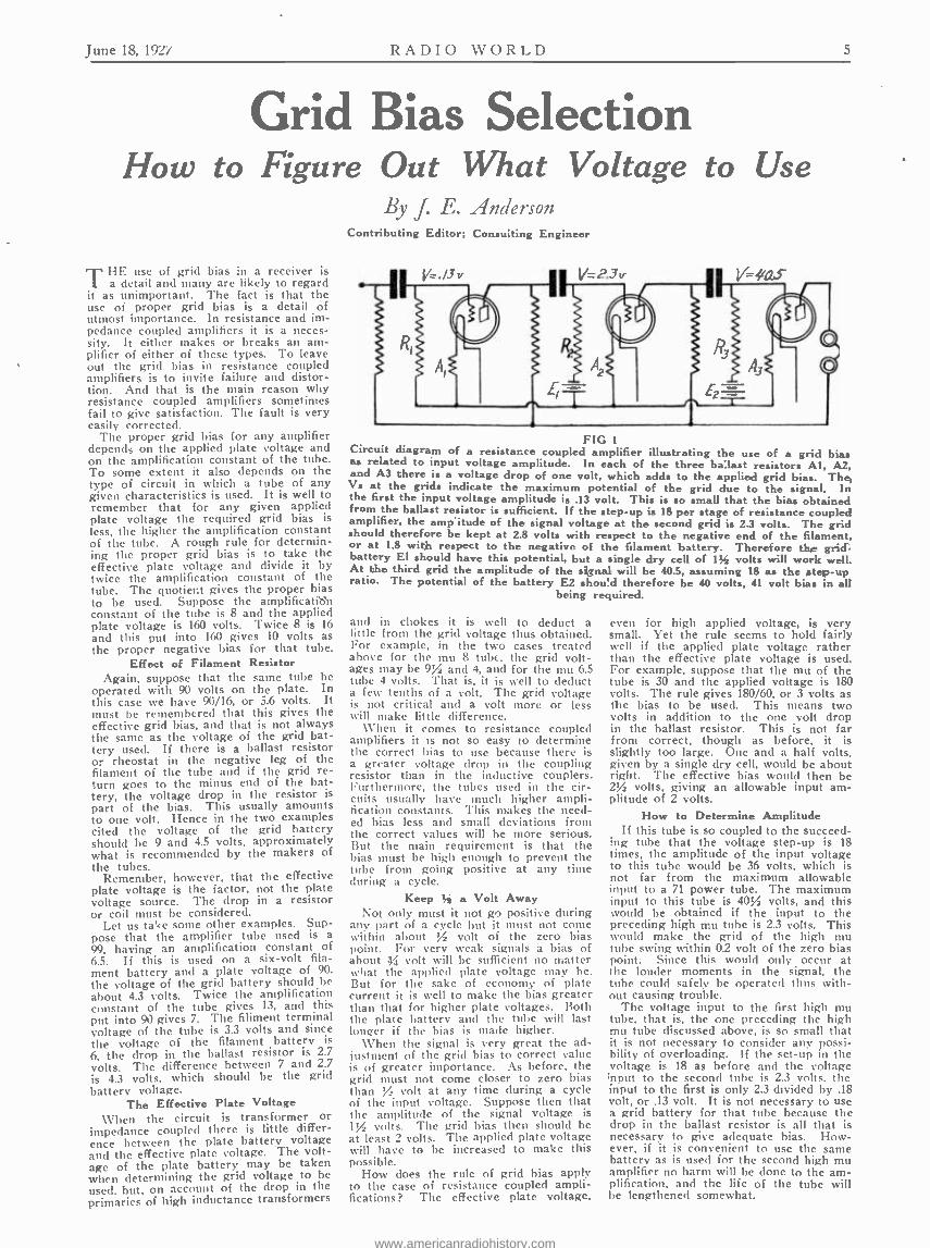
FIG I Circuit diagram of a resistance coupled amplifier illustrating the use of a grid bias as related to input voltage amplitude. In each of the three ballast resistors AI, A2, and A3 there is a voltage drop of one volt, which adds to the applied grid bias. The Vs at the grids indicate the maximum potential of the grid due to the signal. In the first the input voltage amplitude is .13 volt. This is so small that the bias obtained from the ballast resistor is sufficient. If the step -up is 18 per stage of resistance coupled amplifier, the amp itude of the signal voltage at the second grid is 2.3 volts. The grid should therefore be kept at 2.8 volts with respect to the negative end of the filament, or at 1.8 with respect to the negative of the filament battery. Therefore the grid. battery El should have this potential, but a single dry cell of 1% volts will work well. At the third grid the amplitude of the signal will be 40.5, assuming 18 as the step -up ratio. The potential of the battery E2 shoú d therefore be 40 volts, 41 volt bias in all
being required.
and in chokes it is well to deduct a little from the grid voltage thus obtained. For example, in the two cases treated above for the mu 8 tube, the grid volt- ages may be 9% and 4, and for the mu 6.5 tube 4 volts. That is, it is well to deduct a few tenths of a volt. The grid voltage is not critical and a volt more or less will make little difference.
When it comes to resistance coupled amplifiers it is not so easy to determine the correct bias to use because there is a greater voltage drop in the coupling resistor than in the inductive couplers. Furthermore, the tubes used in the cir- cuits usually have much higher ampli- fication constants. This makes the need- ed bias less and small deviations from the correct values will be more serious. But the main requirement is that the bias must be high enough to prevent the tube from going positive at any time during a cycle.
Keep ' a Volt Away Not only must it not go positive during
any part of a cycle but it must not come within about % volt of the zero bias point. For very weak signals a bias of about 3 volt will be sufficient no matter what the applied plate voltage may be. But for the sake of economy of plate current it is well to make the bias greater than that for higher plate voltages. Both the plate battery and the tube will last longer if the bias is made higher.
When the signal is very great the ad- justment of the grid bias to correct value is of greater importance. As before, the grid must not come closer to zero bias than % volt at any time during a cycle of the input voltage. Suppose then that the amplitude of the signal voltage is PA volts. The grid bias then should be at least 2 volts. The applied plate voltage will have to be increased to make this possible.
How does the rule of grid bias apply to the case of resistance coupled ampli- fications? The effective plate voltage,
even for high applied voltage, is very small. Yet the rule seems to hold fairly well if the applied plate voltage rather than the effective plate voltage is used. For example, suppose that the mu of the tube is 30 and the applied voltage is 180 volts. The rule gives 180/60, or 3 volts as the bias to be used. This means two volts in addition to the one volt drop in the ballast resistor. This is not far from correct, though as before, it is slightly too large. One and a half volts, given by a single dry cell, would be about right. The effective bias would then be 2% volts, giving an allowable input am- plitude of 2 volts.
How to Determine Amplitude If this tube is so coupled to the succeed-
ing tube that the voltage step -up is 18 times, the amplitude of the input voltage to this tube would be 36 volts, which is not far from the maximum allowable input to a 71 power tube. The maximum input to this tube is 40% volts, and this would be obtained if the input to the preceding high mu tube is 2.3 volts. This would make the grid of the high mu tube swing within 02 volt of the zero bias point. Since this would only occur at the louder moments in the signal, the tube could safely he operated thus with- out causing trouble.
The voltage input to the first high mu tube, that is, the one preceding the high mu tube discussed above, is so small that it is not necessary to consider any possi- bility of overloading. If the set -up in the voltage is 18 as before and the voltage ;nput to the second tube is 2.3 volts, the input to the first is only 2.3 divided by .18 volt, or .13 volt. It is not necessary to use a grid battery for that tube because the drop in the ballast resistor is all that is necessary to give adequate bias. How- ever, if it is convenient to use the same battery as is used for the second high mu amplifier no harm will he done to the am- plification, and the life of the tube will he lengthened somewhat.
www.americanradiohistory.com
RADIO WORLD June 18, 1027
B Minus to A Pius or Minus? A Consideration of Short Circuit Effects
A B
By Capt. Peter V. O'Rourke Contributing Editor
FIG. 1 FIG. 2
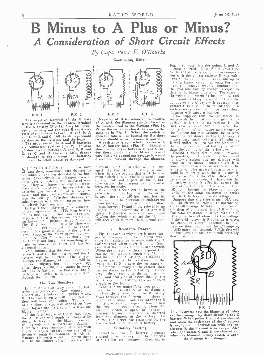
The nega ive terminal of the B bat- tery is connected to the positive terminal of the A battery (Fig. 1). Very litt e dan- ger of burning out the tube if short cir- cuits should occur between A and B, A and C, or B and C. All the damage would be done to the batteries and the leads.
The negatives of the A and B batteries are connected together (Fig. 2). In case of short circuit between A and B, B and C, or C and A there is little danger of damage to the filament but batteries
and the leads would be damaged.
HORT- CIRCUITS will happen now and then, sometimes with disaster to
U1e tubes, other times devastating the bat- teries. Short -circuits will happen even in
these days of orderly, well- insulated wir- ing. They will happen as lung as screw- drivers are poked into the set while the batteries are turned on, or as long as solder and nuts and screws are dropped into the wiring. \Vhether disaster re- sults depends to a certain extent on how the circuit has been wired up.
In Fig. 1 the positive of A is connected to the negative of B. (The long battery line is positive, the short line negative.) Suppose that a short- circuit should oc- cur between the points marked A and B.
The B battery alone will be short -cir- cuited, but the tube will not be endan- gered. No good is done to the B bat- tery. Suppose the short occurs between C and A. The A battery is shorted but the tube is not hurt. But something will begin to smoke the short will last for a second or two.
Now, suppose that the short occurs be- tween B and C. Both the A and the B
battery will be shorted. The current through the filament of the tube will be increased slightly but not dangerously, unless there is a large resistance in series with the A battery. In that case the B
battery will drive a dangerous current through the filament.
The Two Negatives
In Fig. 2 the two negatives of the bat- teries are connected. Now suppose that a short occurs between the points A and B. The two batteries will be shorted but they will buck each other. The extent of Cie short circuit will depend on how much higher the plate voltage is than the filament voltage.
If the A battery is of the storage .type, the A battery will simply be charged by the B battery, and the filament current will be only slightly increased. Again if
there is a large resistance in series with the A battery, a dangerous current will be driven through the filament. If this re- sistance is in series with the filament they^ will be no danger of a burnout of the
FIG. 3 FIG. 4
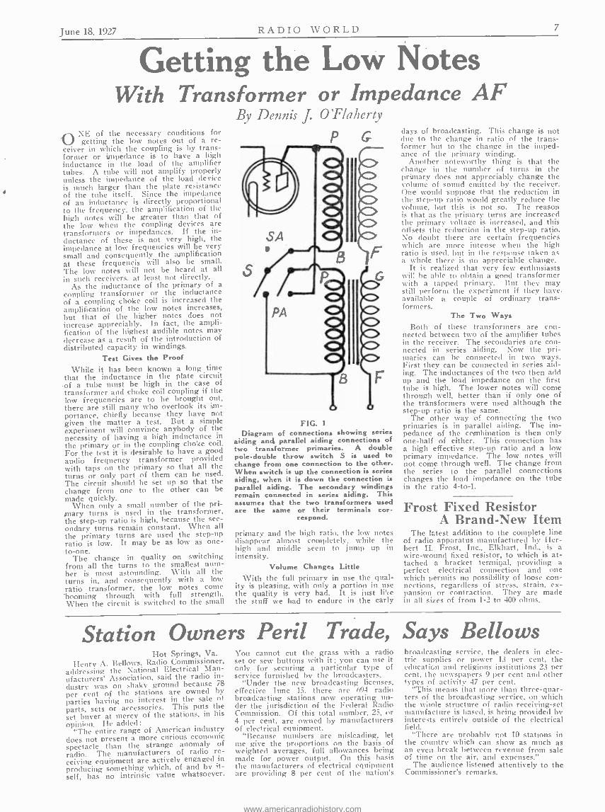
Negative of B is connected to positive of A with the filament switch placed in the positive lead to the filament (Fig. 3). When the switch is closed the case is the same as in Fig. 1. When the switch is open the tube will be burned out if a short circuit should occur between A and B.
A resistance is connected in series with the A battery lead (Fig. 4). Should a short circuit occur between B and C un- der these conditions the filament would very likely be burned out because R would divert the current through the filament.
filament, but the batteries will be dam- aged. If the filament battery is open when the short occurs, that is, if the fila- ment switch is open and is located in one of the leads not a part of the B bat- tery circuit, the filament will of course burn out instantly.
If a short circuit occurs between the points A and B in Fig. 3 when the switch is open the tube will burn out, but the tube will not be particularly endangered when the switch is closed. If the short occurs between D and B the tube is in no danger, but of course the B battery will suffer. If the short occurs between B and C when the switch is closed the filament will receive little more than normal cur- rent.
The Resistance Danger Fig. 4 illustrates why there is more dan-
ger of burning out the filament when there is a resistance in series with the :\ battery than when there is none. Sup- pose that the points C and B are shorted. When the current reaches the point C it can go two ways, through the filament and through the A battery. It divides in inverse ratio to the resistance in tit,. branches. If R is zero the resistance of the filament is many times greater than the resistance in the A battery. Hence very little current goes through the fila- ment and nearly all of it goes through th, A battery. The battery acts as a shore circuit to the filament.
When the resistance R is large as coni- pared to the resistance of the filament. most of the current from the B batter flows through the filament and there is danger of burning it out. The larger the R is the greater the danger. Hence when the circuit is open, that is, when the filament switch is open the danger is greatest, because no current is diverted from the filament to the battery. Of course, the larger the resistance R, the less current flaws in the B battery.
C Battery Shorting Sometimes the C battery becomes
shorted in such a way that the filaments of the tubes are damaged. Referring to
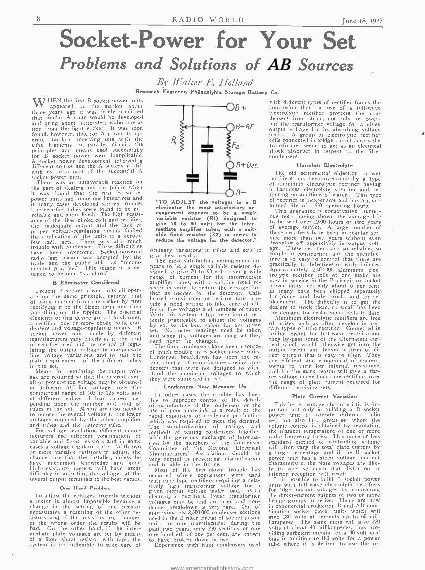
Fig. 5, suppose that the points C and A become shorted. Now if the resistance of the C battery is negligible in compari- son with the ballast resistor R, the volt- ages of the A and C batteries add up to drive a larger current through the fila- ment r. Damage results. Suppose that the grid bias battery voltage is equal to that of the filament battery. The current through the filament is just doubled and a burnout is likely to result. Often the voltage of the C battery is several times greater than that of the A battery. In such cases a short circuit of very short duration will cause a burnout.
Now suppose that the resistance in series with the C battery is large in com- parison with the ballast resistor R. In that case a short circuit between the points A and C will cause no damage to the filament but will damage the battery. Since the resistance in the C battery is always very small, only a small value of R will suffice to burn out the filament if the voltage of the grid battery is larger than the voltage of the A battery.
Should a short circuit occur between the points C and B, both the batteries will be short -circuited but no damage will occur to the filament unless there is a considerable resistance in series with the A battery. The greatest resistance that could be in series with the A battery is infinite, which is the case when the A battery switchc is open. In that event the C battery alone is effective across the filament of the tube. The current that will flow through the filament then de- pends on the total resistance in series with the C battery and on its voltage.
Suppose that the tube is an -OlA and that the circuit is designed to operate on a six -volt storage battery. The value of r is then 20 ohms and that of R 4 ohms. The total resistance in series with the C battery is then 24 ohms. If the voltage of the grid battery is 9 volts, as is often the case, the current through the fila- ment on short circuit will be 3/8 ampere, or 50% more than normal. While this will not burn out the filament it will certainly horten its life.
I Ill II 111111111111 FIG. 5
This illustrates how the filaments of tubes can be damaged by short -circuiting the C battery. When points C and A are shorted and when the resistance of the C battery is negligible in comparison with the re- sistance R the filament is in danger. Also when the points C and B are shorted and when the filament battery switch is open,
the filament is in danger.
www.americanradiohistory.com
June 18, 1927 RADIO WORLD 7
Getting the Low Notes With Transformer or Impedance AF
By Dennis J. O'Flaherty NE of the necessary conditions for getting the low notes out of a re-
ceiver in which the coupling is by trans- former or impedance is to have a high inductance in the load of the amplifier tubes. A tube will not amplify properly unless the impedance of the load device is much larger than the plate resistance of the tube itself. Since the impedance of an inductance is directly proportional to the frequency, the amplification of the high notes will be greater than that of the low when the coupling devices are transformers or impedances. If the in- ductance of these is not very high, the impedance at low frequencies will be very small and consequently the amplification at these frequencis will also be small. The low notes will not be heard at all in such receivers. at least not directly.
As the inductance of the primary of a coupling transformer or the inductance of a coupling choke coil is increased the amplification of the low notes increases, but that of the higher notes does not increase appreciably. In fact, the ampli- fication of the highest audible notes may decrease as a result of the introduction of distributed capacity in windings.
Test Gives the Proof
While it has been known a long time that the inductance in the plate circuit of a tube must be high in the case of transformer and choke coil coupling if the low frequencies are to be brought out, there are still many who overlook its im- portance, chiefly because they have not given the matter a test. But a simple experiment will convince anybody of the necessity of having a high inductance in the primary or in the coupling choke coil. For the test it is desirable to have a good audio frequency transformer provided with taps on the primary so that all the turns or only part of them can be used. The circuit should be set up so that the change from one to the other can he made quickly.
When only a small number of the pri- mary turns is used in the transformer, the step -up ratio is high, because the sec- ondary turns remain constant. When all the primary turns are used the step -up ratio is low. It may be as low as one - to -one.
The change in quality on switching from all the turns to the smallest num- ber is most astounding. With all the turns in, and consequently with a low ratio transformer, the low notes conic booming through with full strength. When the circuit is switched to the small
P G
FIG. 1
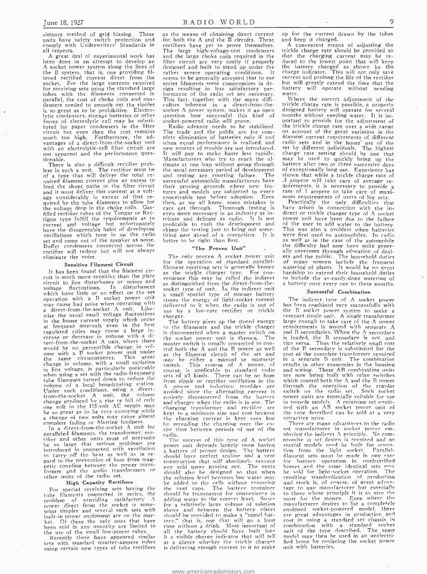
Diagram of connections showing series aiding and parallel aiding connections of two transformer primaries. A double pole -double throw switch S is used to change from one connection to the other. When switch is up the connection is series aiding, when it is down the connection is parallel aiding. The secondary windings remain connected in series aiding. This assumes that the two transformers used are the same or their terminals cor-
respond.
primary and the high ratio, the low notes disappear almost completely, while the high and middle seem to jump up in intensity.
Volume Changes Little With the full primary in use the qual-
ity is pleasing, with only a portion in use the quality is very bad. It is just li' <e the stuff we had to endure in the early
days of broadcasting. This change is not due to the change in ratio of the trans- former but to the change in the imped- ance of the primary winding.
Another noteworthy thing is that the change in the number of turns in the primary does not appreciably change the volume of sound emitted by the receiver. One would suppose that the reduction in the step -up ratio would greatly reduce the volume, but this is not so. The reason is that as the primary turns are increased the primary voltage is increased, and this offsets the reduction in the step -up ratio. No doubt there are certain frequencies which are more intense when the high ratio is used, but in the response taken as a whole there is no appreciable change.
It is realized that very few enthusiasts will be able to obtain a good transformer with a tapped primary. But they may still perform the experiment if they have. available a couple of ordinary trans- formers.
The Two Ways Both of these transformers are con-
nected between two of the amplifier tubes in the receiver. The secondaries are con- nected in series aiding. Now the pri- maries can be connected in two ways. First they can be connected in series aid- ing. The inductances of the two then add up and the load impedance on the first tube is high. The lower notes will come through well, better than if only one of the transformers were used although the step -up ratio is the same.
The other way of connecting the two primaries is in parallel aiding. The im- pedance of the combination is then only one -half of either. This connection has a high effective step -up ratio and a low primary impedance. The low notes will not come through well. The change from the series to the parallel connections changes the load impedance on the tube in the ratio 4 -to -1.
Frost Fixed Resistor A Brand -New Item
The latest addition to the complete line of radio apparatus manufactured by Her- bert H. Frost, Inc., Elkhart, Incl., is a wire -wound fixed resistor, to which is at- tached a bracket terminal, providing a perfect electrical connection and one which permits no possibility of loose con- nections, regardless of stress, strain, ex- pansion or contraction. They are made in all sizes of from l -2 to 400 ohms.
Station Owners Peril Trade, Says Bellows Hot Springs, Va.
Henry A. Bellows, Radio Commissioner, addressing the National Electrical Man- ufacturers' Association, said the radio in- dustry was on shaky ground because 78
per cent of the stations are owned by
parties having no interest in the sale or parts, sets or accessories. This puts the set buyer at mercy of the stations, in his opinion. He added :
"The entire range of American industry does not present a more curious economic spectacle than the strange anomaly of radio. The manufacturers of radio re- ceiving equipment are actively engaged in producing something which, of and by it- self, has no intrinsic value whatsoever.
You cannot cut the grass with a radio set or sew buttons with it : you can use it only for securing a particular type of service furnished by the broadcasters.
"Under the new broadcasting licenses, effective Tune 15, there are 694 radio broadcasting stations now operating un- der the jurisdiction of the Federal Radio Commission. Of this total number, 25, or 4 per cent, are owned by manufacturers of electrical equipment.
"Because numbers are misleading, let me give the proportions on the basis of weighted averages, full allowances being made for power output. On this basis the manufacturers of electrical equipment are providing 8 per cent of the nation's
hroadeastintz service, the dealers in elec- tric supplies or power 13 per cent. the education and religious institutions 23 per cent, the newspapers 9 per cent and other types of activity 47 per cent.
"This means that more than three -quar- ters of the broadcasting service, on which the whole structure of radio receiving -set manufacture is based. is being provided by interests entirely outside of the electrical field.
"There are probably not 10 stations in the country which can show as much as an even break between revenue from sale of time on the air. and expenses."
The audience listened attentively to the Commissioner's remarks.
www.americanradiohistory.com
RADIO WORLD June 18, 1927
Socket -Power for Your Set Problems and Solutions of AB Sources
By Walter E. Holland Research Engineer, Philadelphia Storage Battery Co.
WHEN the first B socket power units appeared on the market about
three years ago it was freely predicted that similar A units would be developed and bring about batteryless radio opera- tion from the light socket. It was soon found, however, that for A power to op- erate standard receiving sets with the tube filaments in parallel circuit, the principles and means used successfully for B socket power were inaoplicable. A socket power development followed a different course and the A battery is still with us, as a part of the successful A socket power unit.
There was an unfavorable reaction on the part of dealers and the public when it was found that the first B socket power units had numerous limitations and in many cases developed serious trouble. The rectifier tubes were found to be un- reliable and short -lived. The high resist- ance of the filter choke coils and rectifier, the inadequate output and the lack of proper voltage -regulating means limited the application of the units to a certain few radio sets. There was also much trouble with condensers. These difficulties have been overcome. Socket -powered radio last season was accepted by the trade and the public alike as "recom- mended practice." This season it is de- stined to become "standard."
B Eliminator Considered Present B socket power units all oper-
ate on the same principle, namely, that of using current from the socket by first rectifying it to the direct form and then smoothing out the ripples. The essential elements of this device are a transformer, a rectifier, one or more choke coils, con- densers and voltage -regulating means. B socket power units made by. different manufacturers vary chiefly as to the kind of rectifier used and the method of regu- lating the output voltage to compensate line voltage variations and to suit the plate requirements of the different tubes in the set.
Means for regulating the output volt- age are required so that the desired over- all or power -tube voltage may be obtained at different AC line voltages over the commercial range of 105 to 125 volts and at different values of load current de- pending upon the number and kind of tubes in the set. Means are also needed to reduce the overall voltage to the lower voltages required by the other amplifier and tubes and the detector tube.
For voltage regulation, different manu- facturers use different combinations of variable and fixed resistors and in some cases a voltage regulator tube. With two or more variable resistors to adjust, the chances are that the installer, unless he have uncommon knowledge and good high -resistance meters, will have great difficulty in adjusting the voltages at the several output terminals to the best values.
One Hard Problem To adjust the voltages properly without
a meter is almost impossible because a change in the setting of one resistor necessitates a resetting of the other re- sistors and if the resistors are changed in the wrong order the results will be bad. On the other hand, if the inter- mediate plate voltages are set by means of a fixed shunt resistor with taps, the system is too inflexible to take care of
8+
B+ RF-
2 R
B+ bet.
T ADJUST the voltages in a B
eliminator the most satisfactory ar- rangement appears to be a single variable resistor (RI) designed to give 70 to 90 volts for the inter- mediate amplifier tubes, with a suit- able fixed resistor (R2) in series to reduce the voltage for the detector."
ordinary variations in tubes and sets to give best results.
The most satisfactory arrangement ap- pears to be a single variable resistor de- signed to give 70 to 90 volts over a wide range of current for the intermediate amplifier tubes, with a suitable fixed re- sistor in series to reduce the voltage fur- ther as needed for the detector. Cali- brated transformer or resistor taps pro- vide a fixed setting to take care of dif- ferent line voltages and numbers of tubes. With this system it has been found per- fectly practicable to adjust the voltages by ear to the best values for any given set. No meter readings need be taken and when the voltages are once set they need never be changed.
The filter condensers have been a source of much trouble in B socket power units. Condenser breakdown has been the re- sult, chiefly, of manufacturers using con- densers that were not designed to with- stand the maximum voltages to which they were subjected in use.
Condensers Now Measure Up In other cases the trouble has been
due to improper control of the details of manufacture of the condensers or the use of poor materials as a result of the rapid expansion of condenser production which was required to meet the demand. The standardization of ratings and methods of testing condensers, together with the generous exchange of informa- tion by the members of the Condenser Committee of the National Electrical Manufacturers' Association, should be very helpful in preventing misapplication and trouble in the future.
Most of the breakdown trouble has occurred where condensers were used with tube -type rectifiers requiring a rela- tively high transformer voltage for a given output voltage under load. With electrolytic rectifiers, lower transformer voltages may be and are used and con- denser breakdown is very rare. Out of approximately 2,500,000 condenser sections used in the B filter circuit of socket power units by one manufacturer during the past two years, only 250 sections or one one -hundreth of one per cent. are known to have broken down in use.
Experience with filter condensers used
with different types of rectifier forces the conclusion that the use of a full -wave electrolytic rectifier protects the con- densers from strain, not only by lower- ing the transformer voltage for a given output voltage but by absorbing voltage peaks. A group of electrolytic rectifier cells connected in bridge circuit across the transformer seems to act as an electrical shock absorber in respect to the filter condensers.
Harmless Electrolyte The old sentimental objection to wet
rectifiers has been overcome by a type of aluminum electrolytic rectifier having a harmless electrolyte solution and re- quiring no additions of water. This type of rectifier is inexpensive and has a guar- anteed life of 1,650 operating hours.
This guarantee is conservative, numer- ous tests having shown the average life to be well over 2,000 hours or two years of average service. A large number of these rectifiers have been in regular ser- vice more than two years without even dropping off appreciably in output volt- age. These rectifiers are so reliable, so simple in construction and the manufac- ture is so easy to control that there are practically no defectives or early failures. Approximately 2,000,000 aluminum elec- trolytic rectifier cells of one make are now in service in the B circuit of socket power units, yet only about 6 per cent. as many have been shipped separately for jobber and dealer stocks and for re- placement. The difficulty is to get the dealers to stock them, so small has been the demand for replacement cells to date.
Aluminum electrolytic rectifiers are free of noises such as often develop in cer- tain types of tube rectifier. Connected in bridge circuit for full -wave rectification, they by -pass some of the alternating cur- rent which would otherwise get into the output circuit and deliver a form of di- rect current that is easy to filter. They are efficient and economical of current, owing to their low internal resistance, and for the same reason will give a flat- ter voltage curve than tube rectifiers over the range of plate current required for different receiving sets.
Plate Current Variation This better voltage characteristic is im-
portant not only in building a B socket power unit to operate different radio sets but also in a given set where the volume control is obtained by regulating the filament temperature of one or more radio -frequency tubes. This more or less standard method of controlling volume will often vary the total plate current by a large percentage, and if the B socket power unit has a steep voltage- current characteristic, the plate voltages are like- ly to vary so much that distortion or inferior reception will result.
It is possible to build B socket power units with full -wave electrolytic rectifiers for high output voltages by connecting the direct- current outputs of two or more bridge groups in series. There are now in commercial production B and AB com- bination socket power units which will give 180 volts at currents up to 60 mil- liamperes. The same units will give 220 volts at about 40 milliamperes. thus pro- viding sufficient margin for a 40 -volt grid bias in addition to 180 volts for a power tube where it is desired to use the re-
www.americanradiohistory.com
June 18, 1927 RADIO WORLD 9
&istance method of grid biasing. These units have safety switch protection and comply with Underwriters' Standards in all respects.
A great deal of experimental work has been done in an attempt to develop an A socket power system along the lines of the B system, that is, one providing fil- tered rectified current direct from the socket. For the large currents required for receiving sets using the standard large tubes with the filaments connected in parallel, the cost of choke coils and con- densers needed to smooth out the ripples is so great as to be prohibitive. Electro- lytic condensers, storage batteries or other forms of electrolytic cell may be substi- tuted for paper condensers in the filter circuit but even then the cost remains much too high. Furthermore, the ad- vantages of a direct- from -the -socket unit with an electrolytic -cell filter circuit are not apparent and the performance ques- tionable.
There is also a difficult rectifier prob- lem in such a unit. The rectifier must be of a type that will deliver the total re- quired filament current plus an excess to feed the shunt paths in the filter circuit and it must deliver this current at a volt- age considerably in excess of that re- quired by the tube filaments to allow for the voltage drop in the choke coils. Gas - filled rectifier tubes of the Tungar or Rec- tigon type fulfill the requirements as to current and voltage but unfortunately have the disagreeable habit of developing oscillations which tune in on the radio set and come out of the speaker as noise. Buffer condensers connected across the rectifier will reduce but will not always eliminate the noise.
Sensitive Filament Circuit It has been found that the filament cir-
cuit is much more sensitive than the plate circuit to line disturbance or noises and voltage fluctuations. In disturbances which have little or no effect on the set operation with a B socket power unit may cause bad noise when operating with a direct- from -the -socket A unit. Like- wise the usual small voltage fluctuations in the house current supply which occur at frequent intervals even in the best regulated cities may cause a large in- crease or decrease in volume with a di- rect- from -the -socket A unit, where there would he no perceptible change in vol- ume with a B socket power unit under the same circumstances. This great change in volume, with a small variation in line voltage, is particularly noticeable when using a set with the radio -frequency tube filaments turned down to reduce the volume of a local broadcasting station. Under such conditions, using a direct - from- the -socket A unit, the volume change produced by a rise or fall of only one volt in the 115 -volt AC supply may be so great as to be very annoying while a change of two volts may cause almost complete fading or blasting loudness.
In a direct- from -the - socket A unit for paralleled filaments. the transformer: rec- tifier and other units must of necessity he so large that serious problems are introduced in connected with ventilation to carry off the heat as well as in re- gard to the prevention of hum from mag- netic coupling between the power trans- former and the audio transformers or other units of the radio set.
High Capacity Rectifiers For special receiving sets having the
tube filaments connected in series, the problem of providing satisfactory A power direct from the socket is some- what simpler and several such sets with built -in power equipment are on the mar- ket. Of these the only ones that have been sold in any quantity are limited to the use of the small low -power tubes.
Recently there have appeared similar sets with standard quarter- ampere tubes using certain new types of tube rectifiers
as the means of obtaining direct current for both the A and the B circuits. These rectifiers have yet to prove themselves. The large high- voltage -test condensers and the large choke coils required in the filter circuit are very costly if properly designed and built to stand up under the rather severe operating conditions. It seems to be generally accepted that to use series filaments some compromises in de- sign resulting in less satisfactory per- formance of the radio set arc necessary. This fact, together with the many diffi- culties inherent in a direct- from -the- socket A power system, makes it an open question how successful this kind of socket -powered radio will prove.
Radio advance needs to be stabilized. The trade and the public are for com- plete elimination of batteries only if and when equal performance is realized. and new sources of trouble are not introduced. It will pay to make haste less rapidly. Manufacturers who try to reach the ul- timate at one leap without going through the usual necessary period of development and testing are courting failure. The successful automobile manufacturers have their proving grounds where new fea- tures and models are subjected to every conceivable test before adoption. Even then, as we all know. some mistakes in cars get through. Thorough testing is even more necessary in an industry as in- tricate and delicate as radio. It is not profitable to rush the development and skimp the testing just to bring out some- thing new ahead of a competitor. It is better to be right than first.
"The Proven Unit" The only proven A socket power unit
for the operation of standard parallel - filament receiving sets is generally known as the trickle charger type. For con- venience this may be called the indirect as distinguished from the direct- from -the- socket type of unit. In the indirect unit a small special type of storage battery stores the energy of light- socket current delivered to it when the radio is out of use by a low -rate rectifier or trickle charger.
The battery gives up the stored energy to the filaments and the trickle charger is disconnected when a master switch on the socket power unit is thrown. The master switch is usually connected to con- trol both the A and the B power as well as the filament circuit of the set and may he either a manual or magnetic switch. This system of A power, of course. is applicable to standard radio sets of all kinds. There can he no hum from ripple or rectifier oscillation in the A power and indiction troubles are avoided since the alternating current is entirely disconnected from the battery and charger when the radio is in use. The charging transformer and rectifier are kept to a minimum size and cost because the charging current is kept very low by spreading the charging over the en- tire time between periods of use of the radio.
The success of this type of A socket power unit depends largely noon having a battery of prover design. The battery should have perfect sealing and a vent construction that wi 1 absolutely prevent any acid spray passing out. The vents should also he designed so that when the solution level becomes low water nia)' he added to the cells without removing the vent caps. The battery container should be transparent for convenience in adding water to the correct level. Space for a relatively large volume of solution above and between the battery plates should he provided to make a "camel bat- tery," that is, one that will go a lone time without a drink. Most important of all the battery should have built into it a visible charge indicator that will tell at a glance whether the trickle charger is delivering enough current to it to make
up for the current drawn by the tubes and keep it charged.
A convenient means of adjusting the trickle charge rate should be provided so that the charging current may be re- duced to the lowest point that will keep the battery charged as shown by the charge indicator. This will not only save current and prolong the life of the rectifier but will greatly extend the time that the battery will operate without needing water.
Where the correct adjustment of the trickle charge rate is possible, a properly designed battery will operate for several months without needing water. It is im- portant to provide for the adjustment of the trickle charge rate over a wide range on account of the great variation in the filament current requirements of different radio sets and in the hours' use of the set by different individuals. The highest charge rate setting should be one that may be used to quickly bring up the battery after two or three successive days of exceptionally long use. Experience has shown that while a trickle charge rate of .3 ampere will take care of average re- quirements, it is necessary to provide a rate of 1 ampere to take care of maxi- mum requirements of users of big sets.
Practically the only difficulties that have arisen in connection with the in- direct or trickle charger type of A socket power unit have been due to the failure of the user to add water to the battery. This was also a problem when batteries were first used on automobiles. In radio as well as in the case of the automobile the difficulty had now been quite gener- ally overcome through education of deal- ers and the public. The household duties of many women include the frequent watering of plants. It would he no great hardship to extend their household duties to include the as- easily -done watering of a battery once every one to three months.
Successful Combination The indirect type of A socket power
has been combined very successfully with the B socket power system to make a compact single unit. A single transformer large enough to take care of the A power requirements is wound with separate A and B secondaries. When the A secondary is loaded, the B secondary is not. and vice versa. Thus the relatively small cost of the B secondary is substituted for the cost of the comnlete transformer renuired in a separate B unit. The combination results in other economies in the housing and wiring. These AB combination units are now being built with relay switches which control both the A and the B power through the operation of the regular switch on the radio set. Such socket Hower units are especially suitable for use in console models. A receiving set enuip- ned with an AB socket power unit of the tvne described can be sold at a very attractive price.
There are many advantages to the radio set manufacturer in socket power em- ploying the indirect A principle. No com- promise in set design is renuired and no special models need he built for onera- Sinn from the light socket. Parallel - filament sets must he made in any case for battery operation in nnelectrified homes and the same identical sets may he sold for light- socket operation. The resulting standardization of production and stock is, of course. of great advan- tage to any manufacturer hut especially to those whose principle it is to give the most for the money. Even where the manufacturer desires to list a completely equipped socket -powered model, there are great advantages in production and cost in using a standard set chassis in combination with a standard socket unit of the type described. The same model may then he used in an unelectri- fied home by renlacing the socket power unit with batteries.
www.americanradiohistory.com

I: A 11 \V" P. T, D June 18, 1927
The Scientific Miracle of Tube Manufacture
By R. C. Robinson Engineer in Charge, Vacuum Tube Department, General Electric Company The value of research is unquestionably
proven by the worth of the various types of evacuated tubes or bulbs which have been sold during the past few years. Ex- periments, in which sonic material at- tached to lead wires was sealed into glas, vessels and the vessels exhausted be- came of great commercial importance when Edison made his first incandescent lamps in 1879.
The improvements in these lamps up to the present time is a most fascinating story, and represents the wor,c of thou- sands of skilled researchers and the ex- penditure of millions of dollars.
The changes from the bamboo and silk filaments to squirted cellulose, from the plain carbon to treated carbon, later fol- lowed by the Gem filament, the osmium filament ,the tantalum filament, and finally drawn tungsten have brought the incan- descent lamp to the excellence which it has today, as a household necessity.
Progress in Manufacturing At the same time that these changes
were being made equally important ad- vances were going on in the art of assem- bling and exhatisting these lamps. Edi- soil's lamps took hours to exhaust while the present day marvel takes seconds. Originally slow acting mercury pumps were used for this work. These were re- placed by Packard oil pumps, then by Gerycke oil pumps, later by rotary oil pumps, and finally by mercury condensa- tion pumps of the Langmuir type. In order to improve the vacuum obtained with the pumps, they are assisted by different chemicals; in the earlier days by phosphorous in the presence of a glow discharge in the bulb, and later by numer- ous chemical compounds, known as "get- ters," such as various chlorides and flu- orides, which when introduced into the bulb materially improve the performance of the lamp.
Equally as wonderful are the improve- ments in the methods of assembling the lamps. At first all of the work was done by hand, but it is now almost entirely accomplished by machinery, operators be- ing necessary only for loading the ma- chines and final inspection and packing of the lamps. These machines are almost human and are wonderful pieces of mechanism. They blow the bulbs, make the stems from glass tubing, seal them into the bulbs, exhaust them, and even seal off the lamps.
Output 300,000,000 Yearly Some idea of the advance of the art
along these lines is best gained by the statement that more than 300,000,000 vacuum lamps per year are made in ap- proximately one -half the floor space that was necessary for une -half this number six years ago, and that the production per operator, due to the big improvement in machinery, has increased three -fold in the past eight years.
The results of these extended researches and improvemenas have given us a lamp seven times as efficient as Edison's, and one of the few household necessities which have steadily decreased in price. Since 1921 their price has been decreased ten times, so that now they cost us only 49% of what they did in 1914.
Many scientific men, such as Fleming, J. J. Thomson, Richardson, Langmuir, etc., have studied the different phenomena
observed in incandescent lamps. When the lamp is well exhausted they found an electric current would pass from the hot filament, if charged negatively, to a plate which was charged postivelv and scaled into the bulb opposite the filament.
Phenomena More Important The results of these purely scientific in-
vestigations lave been more far -reaching even than those on the incandescent lamp itself. From them have arisen our X -ray tubes, high voltage rectifiers, the entire radio vacuum tube line, photo- electric cells. cathode ray tubes, etc.
Langmuir's studies of the current flow- ing through the space in lamps proved that a hot body in a good vacuum gives off electric particles- electrons -the quan- tity depending on the temperature of the hot body and the material from which it is made.
In the present -day vacuum tubes three types of substances are used as the source of electrons : the oxides of certain metals as calcium, barium. stroniunr, etc.; the pure metals themselves, as tungsten or molybdenum ; and these pure metals mixed with a small amount of thoria.
Oxide Coated on Wire The oxides are coated on a wire like
platinum or nickel and give off their electrons at temperatures below the melt- ing points of these metals. The pure tungsten filaments are operated at about 2,400 degrees to 2,500 degrees K (Kelvin), and those containing thoria around 2,000 degrees K. Operating at the saine tem- perature the emission from thorium is about 5,000 times greater than from tung- sten. A pure thorium filament, however, vaporizes and melts at too low a tem- perature to get sufficient emission from it to make a successful tube. It, how- ever, evaporates much slower when in the form of a thin film on tungsten and so it is used in this condition.
The popular UX201 -A has such a fila- men, a tungsten base containing one or two per cent of thoria. This thoria, at the operating temperature, slowly diffuses to the surface of the filament as thorium metal. The large emission of the thorium is thus secured at the high operating temperature of the tungsten filaments.
Emission 63 Billion Billion
Some idea of the quantity of electrons given off from the hot filament is gained from the fact that 628 x 10" escape per second from one square centimeter surface when the emission current is one ampere.
Under the influence of a high voltage between the anode (plate) and the cathode (filament) the electrons escaping from the hot cathode travel at great speed to the positive anode placed op- posite it. If gas is present it either "poisons" the surface of the emitting cathode or modifies the electron flow so that it destroys the proper characteristics of the tube.
It is, therefore, very important that all the gas possible be removed from the tube. This removal of gas necessitates a great amount of painsta'cing work, which in the case of some of the late. ,r wireless tubes must be carried on for fifteen or twenty hours, during which time they are connected to vacuum pumps. The elements of the tube have to be
carefully prepared before they are sealed into the glass bulbs. It is very essential that these parts be freed from all dirt and grease ad be kept as clean as pos- sible, before mounting them into tubes. They are fired at a high temperature in a reducing atmosphere such as hydrogen, or in a vacuum, to remove all contami- nating oxides, and as much of the oc- cluded gas as possible.
Elaborate Pumps The pumping systems by which these
tubes are exhausted are very elaborate, and in the case of those used for the larger tubes, sometimes cost as much as. $5,000 per unit. The tubes are placed in baking -out ovens and are attached to the pumping system. In order to obtain a sufficiently good vacuum three or more pumps are operated in series : the first one or rough pump is capable of giving a vacuum of 1 man. mercury ; the next about .001 m.m.; and the final approxi- mately .000001 m.m. This last pump is also assisted by chemical means, such as phosphorous pentoxide, to help remove water vapor from the tube, or by a re- frigerant, such as liquid air or chilled brine, to freeze out this moisture.
The exhaust operation is carried out as follows : The bulb is exhausted thor- oughly while it is heated as hot as pos- sible without actually softening the glass (400 degrees to 500 degrees C, depending on the glass used) for periods varying from a few minutes to two hours accord- ing to the size of the tube.
Gases Driven Out This bake -out drives the gases (prin-
cipally water vapor and carbon dioxide) from the glass walls. Next the filaments are burned at temperatures higher than they will be when in service. This re- moves the gases from the filament, leads and supporting anchors.. Finally the anodes, grid structure or other parts must be brought to incandescence to expel their occluded gases. This may be done by heating them in a high frequency electric field, or by bombarding them with electrons from their own cathode.
By using high enough voltage between the cathode and anode (100,000 or more volts in the case of X -ray tubes and high - voltage kenotrons) the electrons strike the anodes with such force that the anode will be brought to a bright incan- descence.
It is easily possible to melt holes through tungsten sheets in this manner, temperatures over 3,000 degrees K being reached in such instances.
This heating of the elements must be continued until as much gas as possible is removed from them.
Symptoms of Gas Presence Presence of gas in the tube is shown by
fluorescent spots on the surface of the glass bulb or by a glow in the bulb itself. When all the gas that can be removed mechanically by pumps has been drawn out, in order still further to improve the vacuum, metallic vapors such as those of phosphorous, magnesium or calcium. etc., are distilled into the bulbs and, con- densing on the inside of the glass walls, unite chemically and physically with the residual gases. The tubes are then sealed off from the pumps by melting, with a gas flame, the glass tube which attaches them to the pump.
Before the tubes can be sold they must be aged and operated at voltages and power outputs greater than will he called for in actual service. These operations still further improve the vacuum as the electrons strike some of the gas molecules so hard that they actually drive the gas into the glass walls of the containing bulb.
This effect is greater the higher the voltages used.
After all these operations the vacuum in (Concluded on next page)
www.americanradiohistory.com
June 18, 1927 RADIO WORLD 11
The kilocycle's Case Argued by Dellinger
\\ ;uliingtun. Recommending the use of "kilocycle"
instead of "meter" in the measurement of radio transmission frequencies, Dr. J. H. Dellinger, radio chief of the Bureau of Standards, in a statement, declared that the decision of the Federal Radio Commission to designate frequencies in kilocycles, instead of wavelengths in meters, generally meets with the approval of radio scientists. The full text of his statement follows:
"The new word (kilocycles) introduced into radio station announcements by or- der of the Federal Radio Commission is one evidence that the Commission is be- ing guided in its decisions by the public interest. The decision to replace meters by kilocyles is in line with scientific ac- curacy as well as greater convenience to the public.
Meters a Bad Habit "The Bureau of Standards, in a state-
ment just issued, points out that the original use of wavelengths and meters was really a mistake, has caused no end of confusion, and has been an obstacle in the path of the serious -minded who sough to learn the principles of radio.
The public lias continued to use meters simply because the habit got started, and for no other reason.
"It is much easier for the radio listener to log the stations on his dials in kilo- cycles because all station frequencies are in even numbers, 620, 630, etc.. spaced 10
kilocycles apart. The wavelength ratings, on the other hand, like 483.6, 475.9, are troublesome and are separated different amounts all over the scale.
"In selecting the even kilocycle ratings the Commission is utilizing the results of several years' experience in the develop - meut of broadcasting. Spacings other than the uniform 10 kilocycles between stations have been tried and have always added to interference. The inherent reason for this is that the radio wave carrying speech or music does not occupy a single sharp frequency. but actually
C,C I ü, a lit lc ',;tiDI 10
kilocycles wide. The Word Analyzed
"The word kilocycle need cause no dis- may. Kilo means thousand and is fatn- iliar to everyone in kilowatt, which means a thousand watts. The other part of the word, cycle, means one complete alterna- tion. The number of kilocycles is the number of thousands of times that the rapidly alternating current in the antenna or the set repeats its flow in either direc- tion in one second.
"When it is necessary to find out the kilocycle rating corresponding to a cer- tain number of meters. or vice versa, it is done by dividing 300.000 by the number. For example, 300 meters corresponds to 1.000 kilocycles, and also 300 kilocycles corresponds to 1,000 meters. In view of the action of the Commission. however, there will probably be very little occa- sion for anyone to make any use of meters. and the need for making the con- version from one to the other will dis- appear.
The Best Trend "While kilocycle is a new word to many
radio listeners it is an established term in radio engineering. On account of its greater convenience, and because the wavelength designation is secondary, con- fusing, and superfluous, engineers have
gone increasingly to the kilocycle basis
in the past four years, and manufac- turers have more and more inclined to marking their dials in kilocycles rather than meters.
"The use of kilocycles was given stand- ing as authoritative American practice when, on the recommendation of the Bureau of Standards representatives, the 1923 National Radio Conference adopted a resolution that stations be rated in kilocycles. The definite adoption of this practice by the Federal Radio Commis- sion is in harmony with the trend of the best radio engineering and manufactur- i n g."
Tube Materials Important (Cmtcfuded frmn preceding page)
many instances is better than .000001
m.m., or in other words, there is less than one molecule of gas left of every 70Q.000,000 originally present in the tube.
To get full emission from the hot cathode, it is absolutely essential to have this high vacuum in the tubes. A very good indication of the perfection of the vacuum is afforded by the use of the so- called 3/2 power law. This law states that the maximum thermionic current be- tween electrodes of any shape varies with the 3/2 power of the voltage between them. It holds true for practically all measurements up to the saturation point. except a few at low voltages. If gas
is present in the space, the law does not hold.
Choose
The materials used for parts of the tube and spacing and shape of the parts, play a very important role in the design and performance of vacuum tubes. Cop- per, nickel, platinum, molybdenum and tungsten are most commonly used for the electrodes, the work which the tube has
to do determining the choice of material. For low power tubes, in which the anodes (plates) do not get reel hot, nickel is
generally used. The larger tubes either have to be water cooled, or have their elements made from the high melting metals, molybdenum and tungsten. The electrodes are shaped and spaced accord- ing to the output and electrical character -
ticc desired. From M. I. T. Technology Engineering
News]
Your Portable Receiver You surely want a portable set for your
vacation. What kind will you build? Get a good view of the field of portable sets
for home constructors by obtaining three issues of RADIO WORLD.
June 11 -The Suit Case Six, a Sensitive Portable, Easy to Operate, by James H. Carroll, Contributing Editor. This set
works from a loop or antenna and has a
stage of tuned RF. two stages of untuned RF, tuned regenerative detector input and
two stages of audio. This set can be built into a fibroid suitcase that can he bought for $2.
May 14 -Three Tube Portable That Works From a Loop and Runs a Speaker, by Herbert E. Hayden.
April 30-A One -Tube Portable, Using a Loop, by Jasper Jellicoe.
Send 45 cents for the June 11. May 14
and April 30 issues. RADIO WORLD, 145
W. 45th St., New York City.
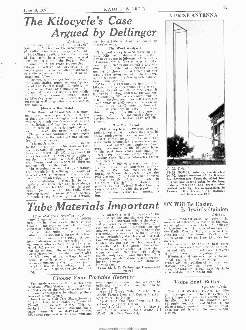
A PRIZE ANTENNA
(F. Í. Delano) THIS NOVEL antenna, constructed by M. Auger, member of the Reseau des Emmetteurs Francais, aided him in receiving second prize in the long distance reception and transmission contest held by this organization in France. His transmitting station's
call letters are 8EB.
DX Will Be Easier, Is Irwin's Opinion
Chicago. Every broadcast station will gain in the
number of listeners by virtue of the new wavelengths, effective June 15, believes G. Clayton Irwin. Jr., general manager of the Radio World's Fair, who is in Chi- cago for the First Annual Trade Show, which opens here on June 13 under his direction.
Listeners will be able to hear more stations than ever before during the Sum- mer and with the Fall will come a revival of DX interest, in his judgment.
Elimination of heterodyning by the na- tional reallocation of wavelengths, to- gether with the splitting of time by many stations provides the opportunity for many broadcasters to gain new friends in near and distant points. he said.
Voice Sent Better Spokane, Wash.
The third Western Electric amplifier with a range from 16 to 7.000 cycles, the latest improved type, has recently been installed at KHQ. This amplifier, with all equipment, cost about $1,000. It has given a much improved tone to the broad- cast, particularly where the voice is con- cerned.
www.americanradiohistory.com
RADIO WORLD June 18, 1927
HIS BIG SET HEAP MUCH FUN
Underwood & Underwuoxl) BESIDES "washing an elephant" there are other "big things" to do, for instance building the biggest set any of your friends have seen. This is what Theodore Hardeen did. Hardeen (at right) plays the set while he does some feats of magic with the aid
of his daughter, Gladys (at left). He is a brother of the late Harry Houdini.
,studios In Chicago To Be Opened by N. B. C.
Merlin H. Aylesworth, president of the National Broadcasting Company, an- nounced that in the early Fall the Na- tional Broadcasting Company will oven studios in Chicago which will supply radio programs to stations of the concern's Red, Blue and Pacific Coast networks.
Chicago has been definitely identified with the National Broadcasting Company since last November, through six stations which have been transmitting network radio programs emanating from New York. These are KYW, WGN. WEBH, WJJD, WMAQ and WQJ. The fact that Julius Rosenwald is a member of the company's advisory council has also given Chicago an established position in the or- ganization, which operates the only na- tional broadcasting service in the United States.
"The opening of Chicago offices and studios is not a departure from the policy of the National Broadcasting Company," Mr. Aylesworth declares.
"We had planned to make Chicago our central source of material for the Uni- versity of the Air, but difficulties arose which made establishing Chicago studios impossible until this time.
"The opening of headquarters in Chi- cago makes possible a more complete (broadcasting service in the Middle West. We are now able to include in our net- works Des Moines, Omaha. Bristow,
Okla, and Dallas, Tex. These cities will be added by direct wires in the Fall when the Chicago studios are complete."
George F. McClelland, vice -president and general manager of the National Broadcasting Company, states, "Members of the engineering staff of our organiza- tion have been ordered to Chicago to start at once with the work of developing the intricate and comprehensive wire fa- cilities necessary to our operations. From row on the time of the National Broad- casting Company's officials is to be divided between Chicago and New York."
Executive offices have already been opened in Chicago. The mechanical steps necessary to the development of adequate studios, facilities and wire connections will require the next ninety days, which will elapse before the formal opening, ac- cording to Mr. Aylesworth, who said that Chicago would then be in the enviable position of serving the nation by radio.
The National Broadcasting Company, with its three networks, covers the entire United States. There are at present on the Red Network twenty -two cities, while eight are associated with the Blue. The Pacific Coast Network, which reaches from Los Angeles to Spokane, includes seven stations.
Officials of the National Broadcasting Company estimate that an audience of 20,000,000 listens to the three chains.
TEACHES PIANO OVER AIR LOS ANGELES.
Aliene Chaudet, piano player and in- structor, has inaugurated a piano teaching class, over KNX, which is proving suc- cessful. All that is necessary to join the class, which is held every Wednesday from 4:30 to 5 P. M., is a radio a piano and a chart which is issued free on re- quest.
SHORT -WAVE SCHEDULE The evening programs of WGY are
now also being broadcast by short -wave stations 2XAF, 32.77 meters, and 2XAD, 22.02 meters. On Tuesday, Thursday and Saturday, 2XAF will do the broadcasting, while on Monday, Wednesday, Friday and Sunday, 2XAD will broadcast.
The short waves travel very far on small power.
NEW HOME, NEW MIC:
WBZA recently moved into a spacious t Hotel Statler, Boston. The photograph si constituting the studio. The first of a n
is installed at
Lindbergh Day A Radio Event J une 11 was "Lindbergh Radio Day"
for the National Broadcasting Company and associated stations throughout the en- tire United States. Lindbergh programs, in addition to the official ceremonies in which the flier participated in Washing- ton, were arranged for WEAF, WJZ, WRC and the Pacific Division.
Arrangements were made with the Washington reception committee, headed by John Hays Hammond, who accepted the National Broadcasting Company's of- fer to link up the entire nation from coast to coact for the broadcasting of the Lind- bergh ceremonies at Washington.
It is estimated 30,000,000 could have tuned in for the event.
Lindbergh's Landing Quickly Announced
Nine minutes after Captain Charles Lindbergh touched French soil on the completion of his New York -to -Paris flight, WGY announced its feat by raido. The speedy service to the waiting fans was made possible through the co- opera- tifn of the United Press.
STATIONS SEND BELLANCA NEWS News was again the spotlight attrac-
tion on the air when Chamberlin and Le- vine winged their way from New York to a point near Berlin, in their Bellanca plane, Columbia, for a record non -stop flight. Stations which broadcast periodic bulletins were swamped with telephone calls, urging them to give the reports more rapidly. WOR, WEAF and WJZ in the metropolitan district won the highest hon- ors for distribution of the news.
www.americanradiohistory.com
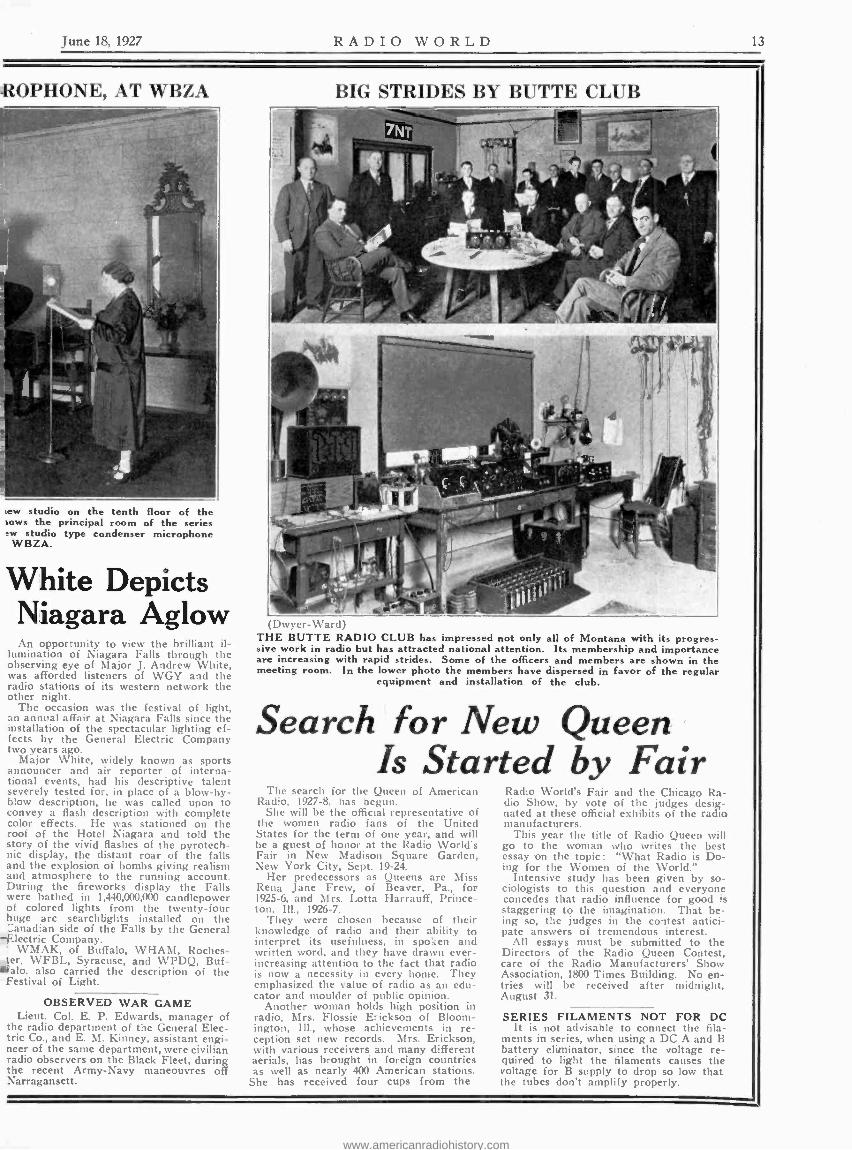
June 18, 1927 RADIO WORLD 1.
-R,OPHONE, AT WBZA
iew studio on the tenth floor of the lows the principal room of the series ew studio type condenser microphone
WBZA.
White Depicts Niagara Aglow An opportunity to view the brilliant il-
lumination of Niagara Falls through the observing eye of Major J. Andrew White, was afforded listeners of WGY and the radio stations of its western network the other night.
The occasion was the festival of light, an annual affair at Niagara Falls since the installation of the spectacular lighting ef- fects by the General Electric Company two years ago.
Major White, widely known as sports announcer and air reporter of interna- tional events, had his descriptive talent severely tested for, in place of a blow -by- blow description, he was called upon to convey a flash description with complete color effects. He was stationed on the roof of the Hotel Niagara and told the story of the vivid flashes of the pyrotech- nic display, the distant roar of the falls and the explosion of bombs giving realism and atmosphere to the running account. During the fireworks display the Falls were bathed in 1,440,000,000 candlepower of colored lights from the twenty -four huge arc searchlights installed on the anadian side of the Falls by the General
-Electric Company. WMAK, of Buffalo, WHAM, Roches-
ter. WFBL, Syracuse, and WPDQ, Buf- salo. also carried the description of the
Festival of Light.
OBSERVED WAR GAME Lieut. Col. E. P. Edwards, manager of
the radio department of the General Elec- tric Co., and E. M. Kinney, assistant engi- neer of the same department, were civilian radio observers on the Black Fleet, during the recent Army -Navy maneouvres off Narragansett.
BIG STRIDES BY BUTTE CLUB
( )%v vv :i1- I
THE BUTTE RADIO CLUB has impressed not only all of Montana with its progres- sive work in radio but has attracted national attention. Its membership and importance are increasing with rapid strides. Some of the officers and members are shown in the meeting room. In the lower photo the members have dispersed in favor of the regular
equipment and installation of the club.
Search for New Queen Is Started by Fair
The search for the Queen of American Radio, 1927 -8, has begun.
She will be the official representative of the women radio fans of the United States for the term of one year, and will he a guest of honor at the Radio World's Fair in New Madison Square Garden, New York City, Sept. 19 -24.
Her predecessors as Queens are Miss Rena Jane Frew, of Beaver, Pa., for 1925 -6, and Mrs. Lotta Harrauff, Prince- ton. Ill., 1926 -7.
They were chosen because of their knowledge of radio and their ability to interpret its usefulness, in spoken and written word, and they have drawn ever - increasing attention to the fact that radio is now a necessity in every home. They emphasized the value of radio as an edu- cator and moulder of public opinion.
Another woman holds high position in radio, Mrs. Flossie Erickson of Bloom- ington, Ill., whose achievements in re- ception set new records. Mrs. Erickson, with various receivers and many different aerials, has brought in foreign countries as well as nearly 400 American stations.
She has received four cups from the
Radio World's Fair and the Chicago Ra- dio Show, by vote of the judges desig- nated at these official exhibits of the radio manufacturers.
This year the title of Radio Queen will go to the woman who writes the best essay on the topic : "What Radio is Do- ing for the Women of the World."
Intensive study has been given by so- ciologists to this question and everyone concedes that radio influence for good is staggering to the imagination. That be- ing so, the judges in the contest antici- pate answers of tremendous interest.
All essays must be submitted to the Directors of the Radio Queen Contest, care of the Radio Manufacturers' Show Association, 1800 Times Building. No en- tries will be received after midnight, lugust 31.
SERIES FILAMENTS NOT FOR DC It is not advisable to connect the fila-
ments in series, when using a DC A and B battery eliminator, since the voltage re- quired to light the filaments causes the voltage for B supply to drop so low that the tubes don't amplify properly.
www.americanradiohistory.com

11 RADIO WORLD June 18, 1027
SIXTH YEAR
The First and Only National Radio Weekly
Member, Radio Publishers Association
Radio World's Slogan: "A radio set for every hems."
TELEPHONES: BRYANT 0558. 0559 PUBLISHED EVERY WEDNESDAY
(Dated Saturday of same week) FROM PUBLICATION OFFICE
HENNESSY RADIO PUBLICATIONS CORPORATION 115 WEST 45th STREET. NEW YORK. N. Y.
'Just Fast of Broadway) ROLAND BURKE HENNESSY. President
M. B. HENNB1sY. Vice- President H(l:R :IAN BERNARD. Secretary
European Representatives: The International News Co. Breams Bides., Chancery Lane. London. Eng.
Paris, France: Brentano's. 8 Avenue de l'Opera
EDITOR. Roland Burke Hennessy MANAGING EDITOR. Herman Bernard TECHNICAL EDITOR. Lewis Winner
CONTRIBUTING EDITORS: 1. E. Anderson. Capt. Peter V. O'Rourke. and
lames H. Carroll
SUBSCRIPTION RATES Fifteen cents a copy. $0.00 year. $3.00 for 4s
months. $1.50 for three months. Add $1.00 a year extra for foreign postage. Canada. 50 cents.
Receipt by new subscribers of the first COPY of RADIO WORLD mailed to them after sending in their order Is automatic acknowledgment of their subscr:ption order. Changes of address should be received at this office two weeks before date of publication. Always give old address: also state whether subscription Is new or a renewal.
ADVERTISING RATES General Advertising
1 Page, 714"x11" 482 lines $300.00 % Page. 7!4 "15%" 231 lines 150.00 r Page. 814" D. C. 231 lines 150.00 % Age. 4%" D. C. 115 lines 76.00
1 Column, 21.4 "zl1" 154 lines 100.00 1 Inch .75 Per Agate Line
Time (Amount 20% 52 consecutive tissues
26 times consecutively or E. O. W. one year.. . . 10%
4 consecutive issues WEEKLY. dated each Saturday. published Wednesday.
Advertising forms close Tuesday, eleven days in advance of date of lssde.
CLASSIFIED ADVERTISEMENTS Ten cents per word. Minimum 10 words. Cash with
order. Business Opportunities ten cents per word. $1.00 minimum.
Entered as second -class matter March 23. 1922. at the Post Office at New York, N. Y., under the Act of
March 3, 1879.
Stations Are Divided On Use of Call Names
Instead of the Letters Answers to the questionnaire mailed to
all broadcasting stations by the National Association of Broadcasters, regarding the substitution of names for call letters, show that the old stations prefer call let- ters, while the new ones desire names. One station which has been on the air for quite a time preferred the use of the name until about 11 P. M., after which the call letters should be used for the inter- est of DX fans.
"To the 681 questionnaires mailed we have received more than 100 replies which point out, in the case of stations estab- lished from three to five years, that call letters are considered as a sort of stock - in -trade which has been expensively es- tablished," said L. S. Baker, secretary of the association. "Younger stations, how- ever, show an inclination to vote 'yes' to the question being considered (names in- stead of call letters). Several have signi- fied that in their estimation, station names once established will prove to be of greater value than call letters."
Wired Radio Lacks Lure of Space Wave
By Hugo Gernsback Editor of "Radio News"
\ \'hen broadcasting was established in this country, the universal opinion was that the service would always be free. No one in America has ever seriously considered broadcasting paid for directly by the listen- ers. This is in distinct contrast to the European system, whereby every radio set is taxed by the government anyywhere from 25 cents a month upwards to pay the broad- casters. This is the custom that prevails in most countries of the world with some few exceptions. Of course, even in the United States, some one foots the bill -that some one being usually the public. But this is indirect taxation, whereas the European system is one of direct taxation on each set.
In America the broadcasters expect to get back. through the returns from good- will programs or indirect advertising, their outlay for broadcasting -in which effort, it may be said, they have been fairly success- ful. Not every station, however, operates at a profit, nor will probably do so for some time to come. In general, the principle has been recognized in this country that radio should be free for all, so that any one buying a set can listen in to his heart's content, year in and year out. This is the prevailing system of "space radio."
Difficulties Solved
There is. however, another system which may shortly go into operation in the Eastern part of the United States, and which is
known under the name of "wired radio." There is nothing new about this, for it is
not a new invention by any means. General G. O. Squier took out patents
on wired radio many years ago, but so far the system has not met with much success or encouragement in application to broad- casting ; although this can be accomplished by wired radio over existing lines, be they telephone or telegraph, electric -light )r power. It is understood that, for the time
being at least, the telephone interests will
have none of wired radio. On the other hand, one of the largest electric light anti
power corporations in the country, with net-
works extending throughout the East, defi-
nitely intends to go "on the wire" with wired broadcasting in the near future, prob- ably within six or eight months.
Many technical difficulties had to be over-
come to make this possible, but officials
of the company sponsoring wired radio no ' believe that the difficulties have been
smoothed out, and that a real service can
actually start very soon. Somewhere in the
East there will be studios where three dif-
ferent wavelengths over existing wire sys-
tems. Choice of Three Programs
By means of a simple switch on a special
receiving set, it is promised, the listener
renting the instrument from the wired -radio
company will be able to select any one of
the three programs being fed to the electric .
light wires. and this program will issue
from a loudspeaker. Two models of re-
ceivers are planned. One will use a crystal
detector, and is intended primarily for head-
phone reception. The other will include a
regular audio amplifier and a loudspeaker,
all A, B, and C power being derived from
the power line. No aerial and ground will
be used. as the receiver picks the pro- grams directly off the power wires.
If one already owns a radio receiver, he
can rent the crystal receiver and connect it
to his set in such a manner that the audio
amplifier in the set will amplify the signals; the radio loudspeaker will then reproduce them as it does space -radio impulses. This is just an outline of the proposal, from the advance information at hand.
Interesting as are the possibilities of wired radio, however, I personally do not be- lieve that it will prove a formidable com- petitor of space radio.
It may be said, as a matter of fact, that the so- called wired radio really should not be called radio at all. although it uses radio instrumentalities throughout. In any event, wired radio certainly takes the romance and thrill out of radio broadcast reception, un- less you are satisfied with one or two local stations. With space radio even a mediocre set has no trouble tuning in any evening at least forty or fifty stations; and if the set is a really good one, as many as a hun- dred stations can be logged.
This does not mean, of course, that you can enjoy a hundred different programs during that evening, because the time limi- tation is against this. But the argument remains in favor of space radio; for the simple reason that, if you wish to stay with any one of the programs, you can do so by tuning in the station you wish to listen to and, unless it is an exceptionally bad night, when much static prevails, there is not much difficulty in staying with the- station selected. If I do not wish to know what is going on in Chicagc, I can listen to Washington or to New York, or to At- lanta. That is, with space radio. With wired radio it would seem that there must he limitation to a very few programs. The fact is, you will have to take what you get. This seems to be a serious disadvantage, and only time will tell whether it can be successfullly overcome.
Assured of Programs On the other hand, it may be said that
with wired radio, you do not have to con- tend with static and uncertainties, but you nay be assured of a program at all times. How this choice will strike the average- listener it is, of course, impossible to predict.
Then comes the most important point under consideration; and that is, wired radio will not be free. The apparatus will not be sold, but leased at a certain monthly rental per instrument.
Just how many persons will avail them- selves of such a service, when general radio entertainment always has been free, remains as yet to be seen. While there can be no doubt that wired radio will in all proba- bility never supplant space radio, it is pos- sible that it will prove an interesting ad- junct to space radio. The parallel to this .
may be found in space radio and the phono- graph.
\ \'hen radio first came into vogue it was freely predicted that the phonograph would be speedily relegated to the scrap heap. r predicted early in 1921. when broadcasting first started, that nothing of the kind was likely to happen. and rather that the phono- graph would he helped by radio. This in- deed proved to he the case, for there are more phonographs and more records being sold today than at any other time.
It is in the nttiire of every radio fan to investigate and the Prediction is freely made that. if wired radio comes into universal use, the parts business will take a sudden lean. Every radio fan and every set builder will no doubt try. at one time or another to.
build a radio receiving set that will bring in the wired -radio program.
(Broadcast from WRNY)
www.americanradiohistory.com

June 18, 1927 RADIO WORLD 15
SHE RUNS WJZ STUDIO WJZ MANAGED
Strand) BERTHA BRAINARD, former news- paper woman, is the manager of WJZ, one of the world's leading broadcast
stations.
Protests Prove Futile On Wave Allocation
The Radio Commission has denied the requests of those stations which wanted a frequency other than the one assigned to them. where decisions have been made. However, other protests are under consid- eration. The following petitions were de- nied:
WJAZ, Chicago, Ill., owned by the Zenith Radio Corporation; assigned 263 meters. protested and requested 389.4 meters.
\VGL. N. Y. City. owned by the Inter- national Broadcasting Corporation; as- signed 256.3 meters, protested and re- quested 422.3 meters.
WDWM. Newark, N. T.. owned by Radio Industries Broadcast ; assigned 236.1 meters, protested and requested 280.2 meters.
The request of WFIW. Hopkinsville, Ky., owned by the Acme Mills, Inc., for the 3612 meter wave, has been withdrawn. The station accepts its assigned wave of 280.2 meters.
Changes Announced In List of Stations
Since the list of stations published in the June 11 issue of RADIO WORLD went to press the Federal Radio Commission announced a few changes, which are pub- lished herewith. Possessors of the list as published should therefore embody the amendments: Station Location Kc M Watts WABI -Bangor, 111e. (will not
divide time with WGBX) 770 389.4 100 WASN- Boston, Mass. 990 302.8 100 WFCI -Pawtucket, R. I 1330 225.4 50 W GBX -I )eleted. WNAC- Boston Mass. (will
not divide with WEAN) 850 352.7 500 WNRC- Greensboro, N. C 1340 223.7 500 WSMK -Dayton, Ohio 1010 296.9 200 WSSH -Boston, Mass. (will not
divide time with WASN). WWNC-Asheville, N. C. 1010 296.9 1000 KFRC -.San Francisco. Calif 660 454.3 500
'Quake Stops Clocks; Station Supplies Time
Los Angeles During a recent earthquake in Mexico.
all of the clocks in the little village of Coronilla were stopped.
An American superintendent of a large mine who owned the only radio set in the town tuned in KFI the following evening and heard the correct time broadcast. Thus the residents of Coronilla were able to resume life on regular schedule.
BY WOMAN WHO
LOVES TO WORK By Herbert B. Glover
Bertha Brainard, manager of W IZ, owned by the Radio Corporation of America, "key" station of the National Broadcasting Company's blue network and one of the country's most powerful radio stations, is not only one of the real pioneers in the radio broadcasting indus- try, but she is thoroughly versed in all its branches.
The State of New Jersey produced both lliss Brainard and the broadcasting sta- tion whose activities she now directs. She was born in South Orange and was grad- uated from the South Orange High School and the Montclair Normal School. Dur- ing her school days she was interested in theatrical work and took part in many amateur performances.
At the outbreak of the World War she enlisted in the motor ambulance section of the American Red Cross. She served with her unit for many months during the hostilities. After the Armistice, she turned to literary pursuits, working for the Fairchild Press.
In New Job When WJZ first came into being, Miss
Brainard immediately realized the poten- tialities of broadcasting. At that time, WJZ was a small station in the experi- mental stage, owned and operated by the Westinghouse Electric and Manufactur- ing Company. It was one of two broad- casting stations in the United States. With her experience as a writer serving as her card of introduction, Miss Brainard interviewed the manager of the station and submitted to him a proposal to con- duct a weekly review of current Broad- way plays from the Newark studio for WJZ's listeners.
Old -timers among broadcast listeners will remember Miss Brainard's weekly theatrical chats, entitled "Broadcasting Broadway." Preparing and presenting them entailed a great deal of work and she received no recompense for it other than a thorough knowledge of the broad- casting methods then in use. She showed such efficiency in her work, however. and she became so popular with the radio audience and with the station's staff, that the management of WJZ soon asked her to serve the station in another capacity.
WJZ needed a representative in New York City. Miss Brainard accepted the position.
Starts Women's Hour When \ViZ's studios and offices were
moved to the Aeolian Building in New York City. Miss Brainard was made as- sistant manager of the station. She was responsible for inaugurating a broadcast hour specially devoted to the interests of women. Under her guidance. the period became immediately and greatly popular.
In the fall of 1926, management of WJZ was taken over by the National Broad- casting Company and Miss Brainard was made manager of the station. Today, she is one of the outstanding women in the radio field and the only woman man- aging a station of the size, the power and the importance of WJZ.
"Radio broadcasting is the most inter- esting game in the world," Miss Brainard declares. "One never does the same thing twice. One night it is visiting celebrities, the next an operatic diva. There is no monotony, hut instead a stream of inter- esting experiences and interesting people."
KAHN'S VERSATILITY
ROGER WOLFE KAHN, leader of the Hotel Pennsylvania Grill Orchestra, which broadcasts from WJZ in New York City, every Tuesday and Friday nights from 10:30 to 11:30 P. M., (E.D.S.T.). Roger is a son of Otto H. Kahn, of the banking firm of Kuhn, Loeb & Co. Otto is head of the Metropolitan Opera House. Roger is not only a player and leader but a
composer.
Fork at Teeth Used By Camper as Phone
When E. C. Hampton of Los Angeles went into the Kings River Canyon in the Sierra Nevadas for the opening of the trout season, he took his portable radio receiving set with him.
When he pitched camp the first night and set up his receiver he discovered to his horror that he had lost his ear phones -and he had purposely left the loud speaker at home to make his load lighter and mere compact. Despair and defeat stared him full in the face for a while and then he started to experiment with some of the implements at hand.
Hampton attached a fish hook to the leadout wire but nothing happened. He then wired a fork to the hook, and still nothing could he heard. Suddenly he re- membered an experiment in bone conduc- tion which he had performed years ago in a high school physics laboratory. His joy was complete, when after setting the dials, he touched the fork to his teeth and heard, clear as a bell, "This is KFI, Los Angeles, the next number will be
Greece Licenses Sets; Prison for Offenders
The Director of Greek Telegraphs. Tele- phones and Posts announced that all owners of radio receiving and broadcasting sets must apply within 15 days to the Ministry of Communications for obtaining the neces- sary license, according to advices to the Department of Commerce from Commercial Attache Gardner Richardson, Athens, Greece.
Failure to apply for such a license within the time limit specified, will be punishable with seizure of the apparatus, up to 12 months' imprisonment and a fine.
www.americanradiohistory.com

RADIO WORLD June 18, 1927
Radio University AFREE Question and An- swer Department con-
ducted by RADIO WORLD for its yearly subscribers only, by its staff of Experts. Address Radio University, RADIO WORLD, 145 West 15th ST., New York City.
When writing for information give your Radio University subscription number
FIG. 541 The panel layout requested by James P. Nuidle
ON PAGE 20 of the Feb. 26 issue of RADIO WORLD there appeared a circuit dia- gram of a trap unit, as sent in by James Wallach. I built this and added it on to my four -tube set and wish to say that it helps immensely in getting distance, as well as increasing the selectivity. How- ever, I note that the volume on local stations is not any greater. Is this char- acteristic of the unit?
(2) -Isn't this unit really an extra stage of radio frequency amplification?
(3) -When I try to tune in the lower wavelengths with this unit in, the set oscillates too much. Would a variable primary or a 2,000-ohm variable resistance in the plate lead of the new tube help any ?-- LESTER MURROW, Jackson, Mich.
(1 and 2) -Yes. (3) -This would help a great deal. In-
crease the number of turns on the pri- mary to twenty -five.
* *
I HAVE the circuit diagram of a five - tube receiver, in which two stages of tuned radio frequency amplification, a non -regenerative detector and two stages of transformer coupled audio frequency amplification are used. A triple con- denser (the capacity of each section being .00035 mfd.) is used to tune the secondaries of the coils, which are of the figure eight type. I would like to build this set. The coils are the only products that I haven't got.
(1) -Could plain solenoids be used? I have plenty of two and three- quarter -inch diameter tubing and No. 22 double cotton :overed wire. If so, give the data.
(2) -A variable grid leak is specified. Could a fixed leak be used?
(3) -If so, please specify the value, using an -OlA tube as a detector.
(4) -A rheostat is used for both radio frequency tube filaments. Is this all right?
(5) -May the coils be tipped at an angle in siThilar fashion to those in a Neutro- dyne?- CHARLES ARTHURS, Cam- bridge, Mass.
(1) -Each primary winding should con- sist of ten turns. Each secondary wind- ing should consist of seventy turns. Be- tween each primary and secondary wind- ing, allow a one -quarter inch space.
(2) -Yes. (3) -Use a four megohm leak. But a
variable one will be better. (4 and 5) -Yes.
* * *
THERE APPEARED on page 10 of the March 12 issue of RADIO WORLD a cir- cuit diagram of a crystal detector re- ceiver. About what is the range of such a set, both in the city and country?
(2) -Would a synthetic crystal work all right here?
(3) -Can the same type of antenna as specified for the average tube set he used, e.g., one hundred feet, inerted L shape? - FRANKLIN L. OSGOOD, Cincinnati, O.
(1) -About fifteen miles, in a fairly good location in the city and about twenty -five miles in the country.
(2 and 3) -Yes. * *
TWO YEARS ago I built a four -tube reflex, the first tube being reflexed, the next being a non -regenerative detector and the following two audio amplifiers, coupled by transformers. I would like to rebuild this set. I use -OlA tubes throughout.
(1) -Could another tube be added in a stage of tuned radio frequency amplifica- tion, using a drum type control with, of course, three condensers?
(2) -If not, could the drum control with two condensers be used just for the de- tector and RF stages?
(3) -Would enother stage of trans- former coupled audio cause distortion?
(4) -The plates of both tubes are now connected to a common B lead, where ninety volts are applied. Also there is no provision for a C battery. Could a higher plate voltage he used on the plate of the last tube for greater volume? What C batteries should be used ? -HAROLD WHITE, Newark, N. J.
(1) -No, this would cause erraticness. (2) -Yes. Be sure that the rotor sec-
tions are not common. If they are, and the grid leak is shunted across the grid condenser, it will be necessary to run the leak from the G post to the plus A post of the socket.
(3) -Yes. (4) -Yes. Use one hundred thirty -five
on the last plate and ninety on the first. The C bias for the first tube should he four and one -half, while for the last tube, it should be nine.
THE ARRANGE MENT shown on page 15 of the Jan. 15 issue of RADIO WORLD, for switching in or out the B eliminator or trickle charger, has attracted my atten- tion and I wish to use it in conjunction with my set. Could the switch he placed on the panel of a receiver, or must it he placed underneath the set? -HENRY KING, Pittsburgh, Pa.
It should be placed in such a position that the AC line is not parallel to the antenna and ground, or the grid and plate It ads. If put on the panel, of course, this would happen. Therefore, beneath the set either in a console compartment or underneath the table, would be all right.
* *
I HAVE a four -tube set, using one tuned stage of radio frequency amplifica- tion, a detector and two transformer audio stages. Rheostats are used in each fila- ment circuit. Could all but the RF rheo- stat he replaced by ballast resistors. I wish to do away with all these knobs on the panel.
(2)-The tuning is quite broad. Could this he due to the closeness of the pri- mary to the secondary, there being no space at all between them? They con-
sist of twenty turns. Is this also too much?
(3) -Would the addition of a coil and variable condenser in series with the an- tenna help the selectiveness of the set? If so, could a .00035 mfd. variable con- denser be used? How should the coil be made ? -ROBERT KEITH, Ft. Wayne, Ind.
(1) -Yes. (2) -Place the primary winding about
one -quarter inch away from the secondary winding. Reduce the primary turns to ten.
(3) -The installation of the variable condenser and coil will help to increase the selectivity as well as the volume of the set. For the .00035 mfd. condenser you have, wind fifty -nine turns on a three - inch diameter tubing using No. 22 double cotton covered wire.
* * *
WHAT IS 9,000 kilocycles equal to in meters?
(2) -What is 150 meters equal to in kilocycles?
(3) -What is 10 meters equal to in kilo- cycles?
(4) -What is 10,000 kilocycles equal to in meters ? -SAMUEL WENTWERTH, Springfield, Ill.
(1) -33.31 meters. (2) -1,999 kilocycles. (3)- 29,982 kilocycles. (4) -29.98 meters.
*
A FRIEND recently gave me the cir- cuit diagram of a five -tube receiver using a single tuned radio frequency stage, a non- regenerative detector and three stages of resistance coupled audio frequency amplification. Will I get good quality re- production?
(2)- Although the set calls for separate condensers, he told me that I could use a double condenser with satisfaction. He also said that the only changes necessary, would he to install small midget con- densers across the condenser for balanc- ing and return the grid to plus A, via the leak. Is this correct?
(3) -Will a seven by twenty -four inch panel and cabinet give me ample space for this set?
(4) -The data calls for a two ohm, one and one -half ampere rheostat to control the filaments of the detector and resist- ance coupled audio tubes. I have a two ohm, two ampere rheostat. Could this be used?
(5) -Could a set of this type be used with much success on a loop? If so, could I follow the directions given in the Nov. 6 issue of Radio World on page 11? -WILLARD ELGIN, Bridgeport, Conn. (1, 2, 3, 4 and 5) -Yes.
*
THE PANEL layout for a five -tube set, using two stages of tuned RF ampli- fication, a detector and two stages of transformer audio coupling, wherein con- trols resembling the Mar -Co Illuminated Controls, except that no light switch is provided with each, a filament switch, a single circuit jack and a single rheostat, which controls the RF tube filaments are used, would be appreciated. -JAMES P. NUIDLE, Hackensack, N. J.
Fig. 541 shows the panel layout. The switch is placed next to the control on the right. The rheostat is placed above the jack in the extreme right hand cor- ner. The panel is of the seven by twenty - four inch type.
* * *
REGARDING THE three -tube regen- erative receiver, described by Jasper Henry in the April 2 issue of RADIO WORLD on page 13.
(1) -Could the first double circuit jack be left out? How?
(2) -Can both audio tubes be placed on a single % ampere ballast resistor?
(3)- Could I substitute the filament con- trol jack with a pair of binding posts, and use the filament switch to disconnect or connect the filament circuit? How?
www.americanradiohistory.com
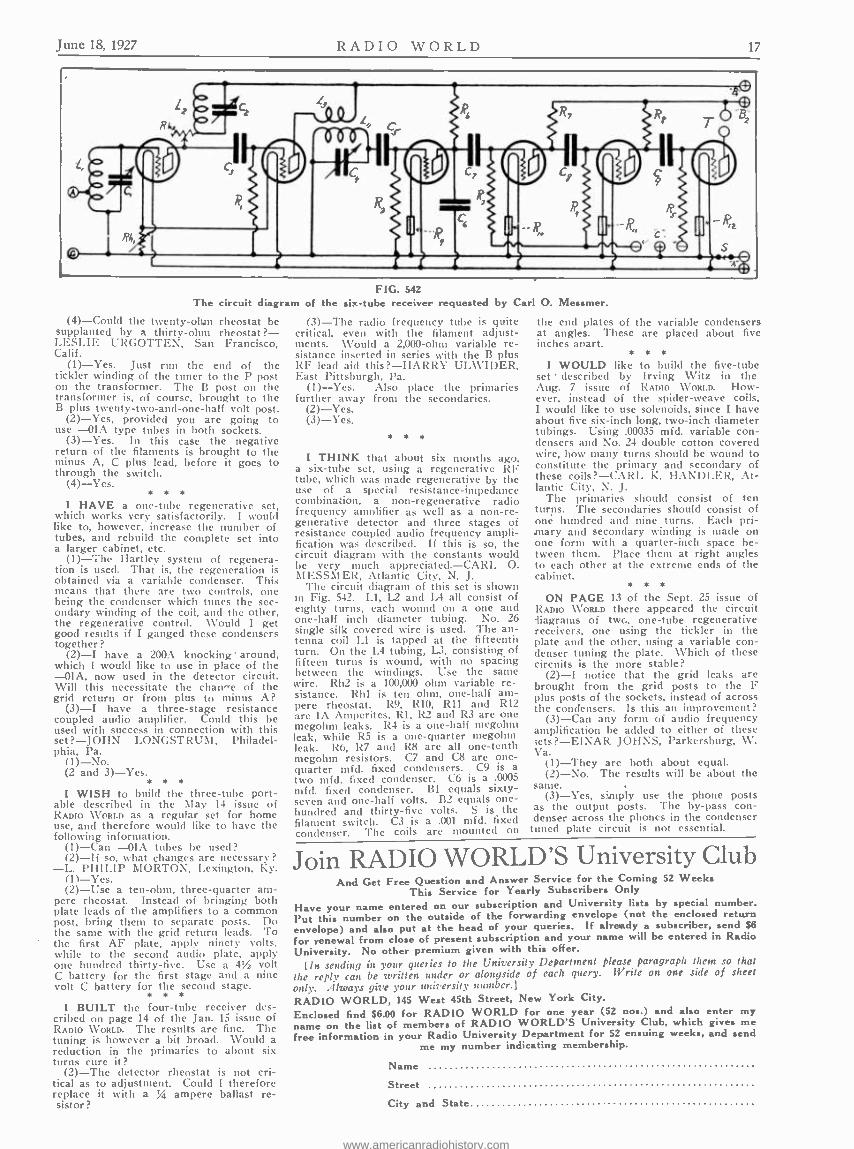
June 18, 1927 RADIO WORLD 17
The circuit diagram of
(4) -Could the twenty -ohm rheostat be supplanted by a thirty -ohm rheostat? - LESLIE URGOTTEN, San Francisco, Calif.
(1) -Yes. Just run the end of the tickler winding of the tuner to the P post on the transformer. The B post on the transformer is, of course, brought to the B plus twenty -two- and -one -half volt post.
(2) -Yes, provided you are going to use -OlA type tubes in both sockets.
(3) -Yes. In this case the negative return of the filaments is brought to the minus A, C plus lead, before it goes to through the switch.
(4) -Yes. * * *
1 HAVE a one -tube regenerative set, which works very satisfactorily. I would like to, however, increase the number of tubes, and rebuild the complete set into a larger cabinet, etc.
(1) -The Hartley system of regenera- tion is used. That is, the regeneration is obtained via a variable condenser. This means that there are two controls, one being the condenser which tunes the sec- ondary winding of the coil, and the other, the regenerative control. Would I get good results if I ganged these condensers together?
(2) -I have a 200A knocking around, which I would like to use in place of the -OlA, now used in the detector circuit. Will this necessitate the chane of the grid return or from plus to minus A?
(3) -I have a three -stage resistance coupled audio amplifier. Could this be used with success in connection with this set? -JOHN LONGSTRUM, Philadel- phia, Pa.
(1) -No. (2 and 3) -Yes.
* * e
I WISH to build the three -tube port- able described in the May 14 issue of RADIO WORLD as a regular set for home use, and therefore would like to have the following information.
(1) -Can -OlA tubes be used? (2) -If so, what changes are necessary?
-L. PHILIP MORTON, Lexington, Ky. (11 -Yes. (2) -Use a ten -ohm, three- quarter am-
pere rheostat. Instead of bringing both plate leads of the amplifiers to a common post, bring them to separate posts. Do the same with the grid return leads. To the first AF plate, apply ninety volts, while to the second audio plate, apply one hundred thirty -five. Use a 4% volt C battery for the first stage and a nine volt C battery for the second stage.
* e e
I BUILT the four -tube receiver des- cribed on page 14 of the Jan. 15 issue of RADIO WORLD. The results are fine. The tuning is however a bit broad. Would a reduction in the primaries to about six turns cure it?
(2) -The detector rheostat is not cri- tical as to adjustment. Could I therefore replace it with a % ampere ballast re- sistor ?
FIG. 542 the six -tube receiver requested by Carl O.
(3) -The radio frequency tube is quite critical, even with the filament adjust- ments. Would a 2,000 -ohm variable re- sistance inserted in series with the B plus RF lead aid this? -HARRY UL \VIDER, East Pittsburgh, Pa.
(1) -Yes. Also place the primaries further away from the secondaries.
(2) -Yes. (3) -Yes.
e e *
I THINK that about six months ago, a six -tube set, using a regenerative RF tube, which was made regenerative by the use of a special resistance- impedance combination, a non- regenerative radio frequency amplifier as well as a non -re- generative detector and three stages of resistance coupled audio frequency ampli- fication was described. If this is so, the circuit diagram with the constants would be very much appreciated. -CARL O. MESSMER, Atlantic City, N. J.
The circuit diagram of this set is shown in Fig. 542. L1, 12 and LA all consist of eighty turns, each wound on a one and one -half inch diameter tubing. No. 26 single silk covered wire is used. The an- tenna coil L1 is tapped at the fifteenth turn. On the L4 tubing, L3, consisting of fifteen turns is wound, with no spacing between the windings. Use the same wire. Rh2 is a 100,000 ohm variable re- sistance. Rhl is ten ohm, one -half am- pere rheostat. R9, R10, R11 and R12 are IA Amperites, Rl, R2 and R3 are one megohnt leaks. R4 is a one -half megohtn leak, while R5 is a one -quarter megohm leak. R6, R7 and R8 are all one -tenth megohm resistors. C7 and C8 are one - quarter mfd. fixed condensers. C9 is a two mfd. fixed condenser. C6 is a .0005 mfd. fixed condenser. BI equals sixty - seven and one -half volts. B2 equals one - hundred and thirty -five volts. S is the filament switch. C3 is a .001 mfd. fixed condenser. The coils are mounted on
Messmer.
the end plates of the variable condensers at angles. These are placed about five inches apart.
I
e e e
WOULD like to build the five -tube set described by Irving Witz in the Aug. 7 issue of RADIO WORLD. How- ever, instead of the spider -weave coils. I would like to use solenoids, since I have about five six -inch long, two -inch diameter tubings. Using .00035 mfd. variable con- densers and No. 24 double cotton covered wire, how many turns should be wound to constitute the primary and secondary of these coils ? -CARL K. HANDLER, At- lantic City, N. J.
The primaries should consist of ten turns. The secondaries should consist of one hundred and nine turns. Each pri- mary and secondary winding is made on one form with a quarter -inch space be- tween them. Place them at right angles to each other at the extreme ends of the cabinet.
e * e
ON PAGE 13 of the Sept. 25 issue of RADIO WORLD there appeared the circuit iiagrams of two, one -tube regenerative receivers, one using the tickler in the plate and the other, using a variable con- denser tuning the plate. Which of these circuits is the more stable?
(2) -I notice that the grid leaks are brought from the grid posts to the F plus posts of the sockets, instead of across the condensers. Is this an improvement?
(3) -Can any form of audio frequency amplification be added to either of these ;ets? -EINAR JOHNS, Parkersburg, W. Va.
(1) -They are both about equal. (2) -No. The results will be about the
same. (3) -Yes, simply use the phone posts
as the output posts. The by -pass con- denser across the phones in the condenser tuned plate circuit is not essential.
Join RADIO WORLD'S University Club And Get Free Question and Answer Service for the Coming 52 Weeks
This Service for Yearly Subscribers Only
Have your name entered on our subscription and University lists by special number. Put this number on the outside of the forwarding envelope (not the enclosed return envelope) and also put at the head of your queries. If already a subscriber, send $6
for renewal from close of present subscription and your name will be entered in Radio University. No other premium given with this offer.
[In sending in your queries to the University Department please paragraph them .co that the reply can be written under or alongside of each query. Write on one side of sheet
only. Always give your unkersity number.]
RADIO WORLD, 145 West 45th Street, New York City.
Enclosed find $6.00 for RADIO WORLD for one year (52 nos.) and also enter my name on the list of members of RADIO WORLD'S University Club, which gives me free information in your Radio University Department for 52 ensuing weeks, and send
me my number indicating membership.
Name
Street
City and State.
www.americanradiohistory.com
RADIO WORLD June 18, 1927
CERTIFIED PARTS and ACCESSORIES
"Ensco" Selectostat Gives Fine Selectivity
A simple device has recently been developed to fill the pressing need for obtaining selectivity without making any
Ac.,AL change in the set itself. This de- vice as shown is merely connected between aerial and set. By means of low- resistance coupling between aerial and ground t h e tuning is
sharpened. This phase of the operation of the device is accomplished without any adjustment. The setting of the first dial (in tuned radio frequency circuits) may be changed slightly, but the selectivity is
obtained without further adjustment, and after learning the exact dial readings they never vary. You merely tune your set as before.
Another valuable use of this device is
as a volume control. Here the adjusting knob is used to vary resistance inserted in the aerial circuit by use of the device. When the knob is at zero it is out of con- tact and the device is merely a means of obtaining selectivity. By turning the knob the resistance is inserted at maxi- mum and gradually reduced until the volume is that desired for the particular program being received. This form of volume control is greatly to be desired as it permits the tubes to operate at best efficiency, which is seldom true when the rheostats are used to reduce volume.
The third feature of importance is the reduction of static effect by use of this device. The adjustment of knob for con- trol of volume also controls a form of static leak between aerial and ground. During periods of heavy static the set is turned to full volume and then controlled by the knob. As the volume is slightly decreased the static is decreased in a
proportionately greater way, thus increas- ing the ratio between static and signal volume and permitting clearer reception. It has been demonstrated that with this inexpensive piece of apparatus programs can be heard with good clarity even in severe electrical storms. Of course no claim is made that static will be entirely eliminated, but any means of reducing it certainly makes for more pleasant sum- mer radio reception.
The Ensco "Selectostat," as this device is called, is the latest development of the Engineers' Service Co., producers of the famous Ensco unit and 36 -inch cone kit, and full information on both of these products may be had by addressing the main office at 25 Church Street, New York City.
"Push Post" Added To Line of X -L Lab.
The X -L Radio Laboratories. 2424 -26 Lincoln Ave., Chicago, Ill., manufacturers of the popular model G and N vario- densers, which range in capacity from
.0000018 mfd. to .001 mfd., are now pro- ducing a new type of binding post known as the X -L Push Post. It is very light, being made of aluminum, and has a high conductivity factor. All that is necessary to connect a lead to the binding post is
to push the top down and insert the lead through a large hole. When you take the pressure off the top, the lead is
rigidly held in place. The contact is positive and strong, no jarring of any kind being able to work it loose.
Concertone Appears In Upright Case
The Concert one audio transformer, made by the Jefferson Elec. Mfg. Co., 501 -511 So. Green St., Chicago, is now
assembled in a beautiful black enameled up- right case. The windings o f this transform- er are vacuum impregnated and the whole assembly seal- ed into the case. This pro- tection makes Concer tone impervious to moisture even in humid cli-
mates. The extra heavy insulation throughout causes less resistance between the primary and the core, which lessens the possibility of electrolytic action.
Concertons is an original straight line "curve" audio transformer. It amplifies evenly all frequencies from 30 to 10,000 cycles. Its design -exact balancing of core and windings- enables the amplifica- tion of overtones and harmonies, so neces- sary in producing truc and natural re- production of voice or instrument.
Tonatrol is Latest Electrad Product
The Phasatrol, the rugged balancing device used in radio frequency amplify- ing circuits, manufactured by Electrad,
THE Electrad Phasatrol Inc., 173 -175 Varick St., New York City, although on the ,market for a short while, has become a real standby with home constructors.
The Tonatrol, the new Electrad volume control, is another popular device. The non- inductive variable high resistances, mica by -pass and filter condensers, lead in connectors, lamp socket antenna, metallic grid leaks and resistances, light- ning arresters, filament switches, jacks, rheostats, potentiometers, complete aerial outfits, grid leak mountings, Audiohm and \"ariolun show the extent and versatility of the Electrad line.
Craftsman Filters A new speaker filter, which works with
sets using under 250 volts, has been developed by the Craftsman Radio Products, 9 Orchard St., Newark, N. J. A speaker filter for use on sets where 180 to 500 volts are used is also manufactured by this concern. Both units are con- tained within a crystallized brown finished case, and furnished complete with tip jacks and leads. The units are very com- pact and rugged, standing up well, when used on voltages much higher than those stated.
Abox Is Producing An A Eliminator
The Abox A Battery Eliminator is a rectifier and an Abox Filter built into one compact unit. It operates direct from the
light socket and contains no storage battery in paste form or other- wise.
It operates on 110 -120 volt AC and delivers enough cur- rent at 6 volts to o p e r a t e eight large tubes. No change in
set wiring is necessary. The Abox A Eliminator replaces the storage battery and charger and operates only while the set is in use.
The Abox is manufactured by the Abox Company, Chicago, under license granted by the Andrews- Hammond Corporation who have spent several years in develop- ment work on the Abox Filter and the Abox A Battery Eliminator.
Amsco Has Couplers For High Mu Tubes
In response to the demand created by the new Cunningham and R. C. A. high mu tubes, Amsco Products, Inc., of New York has added a resistor coupler to their line up resistance coupled amplifying apparatus particularly adapted to the requirements of these new tubes. The tendency to mo- torboat can be satisfactory counteracted by the use of properly designed resistor cou- plers.
Amsco now makes two types of resistor couplers, the RC! for the 201A type of tube, and the RC2 foe the high mu tubes. While either type can be used successfully with all tubes in the average case, the manu- facturer recommends the following com- binations for different amplifiers.
With tubes having an amplification con- stant below 20, the RC1 should be used throughout in two, three and four stage am- plifiers.
With high mu tubes (above 20) two RC2's should be employed in a two stage amplifier. For three stages, two RC2's and one RC1 are recommended, the RC1 being used in the middle stage. This arrange- ment effectively reduces the tendency to motorboat even when the amplifier is oper- ated from a "B" battery eliminator, the staggering of the couplers resulting in dif- ferent time constants for the various cir- cuits. Stabilization is achieved by the prin- ciple of detuning.
Speaker in a Globe The Symphonic Sales Corporation, of
370 Seventh Avenue, New York City, are introducing to the trade the Symphonic Globe Radio loud speaker.
This is a decidedly different speaker in both appearance and quality of tone. In the ball shaped interior there is no vi- bration elsewhere than in the diaphragm of the powerful unit itself.
Lambert Fi iedl, president of the Sym- phonic Sales Corporation, explained the action of the speaker "Speech or music is driven into the dome of the globe, in which space it expands and develops it- self as in a tone chamber or horn. The clarified speech or well- rounded musical tones are emitted with all original fidelity and without the presence of foreign noises."
The globe itself is an accurate full - sized library globe, a post -war map.
www.americanradiohistory.com
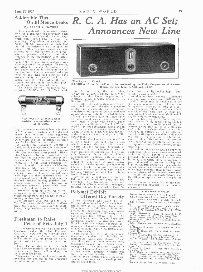
June 18, 1927 RADIO WORLD 1'i
Solderable Tips On El Menco Leaks
By RALPH A. SAYRES The conventional type of fixed resistor
used for a grid leak has invariably been manufactured with metal terminal caps which were slipped into the clips of a mounting. Very often the electrical re- sistance of such mountings is lower than that of the resistor it was designed to support. This type of construction was, at best, but a poor substitute for a per- manent, positive, soldered connection. But, clue to the low melting -point metals used in the construction of the conven- tional type of grid leak, soldering was absolutely out of the question. Of course, any attempt to solder the ordinary car- bon paper resistor is absolutely out of the question. Yet the conventional clip - mounted grid leak and resistors have brought many a receiver back to its maker- express collect -when the only trouble was the simple mechanical prob- lem of insecurely fastened units.
The Electo- Motive Engineering Cor- poration, 127 West 17th St., New York
"HY- WATT" El Menco fixed resistor, conservatively rated
at 12 watts.
City, has overcome this difficulty in their new "Hy- Watt" resistors, grid leaks and heavy duty resistors. And engineers, manufacturers and experimenters have quickly grasped the importance of these new "solderable" resistor units.
A conductive, metallized deposit is fused, at high temperature, into the outer surface of a vitreous tube. The ends of this tube are then silver -plated. Silver - plated because silver is recognized as the best electrical conductor and affords per- fect contact. The "Hy- Watt" unit is then "spiralled" to the exact resistance de- sired. A method far more satisfactory than any in which an attempt is made to gauge the resistance accurately by me- chanical means. Tinned terminal caps with lugs are then eyeletted onto the silver -plated ends of the unit and the finished product having positive, non - arcing contact from lug to lug give an absolutely noiseless, permanently accu- rate Grid Leak or Resistor.
"Hy- Watt" units are then treated with a special paint which "seals -in" their matchless accuracy and renders them ab- solutely moisture- proof.
The ordinary grid leak type of "Hy- Watt" is conservatively rated at 6 Watts while the standard ranges of "Hy- Watt" Heavy Duty Resistors dissipate up to 12 watts.
Freshman to Raise Price of Sets July 1
In a telegram sent out to all authorized Freshman dealers. the Chas. Freshman Co., Inc., of New York and Chicago, man - ufacturers of Freshman Masterpiece radios. states that list prices on all re- ceivers will increase 10 per cent on July 1.
The telegram also notifies the trade that all orders received for immediate de- livery prior to July 1 will be shipped at the present list prices.
This price increase applies only to the receiving sets and not to the Freshman line of power accessories.
R. C. A. Has an AC Set; Announces New line
(Courtesy of R. C. A.) RADIOLA 17, the first AC set to be marketed by the Radio Corporation of America.
It uses the new tubes, UX226 and UY227.
An AC set, using the new tubes, UX220 and ÚY227, is among the new re- ceivers of the Radio Corporation of America, which recently announced its line for 1927 -1928.
This set is the culmination of years of research in set and tube design aimed to produce, for a moderate price, a receiver completely AC operated with a minimum of operation controls. It is called Radiola 17, and has three stages of tuned radio frequency amplification, tube detector and two stages of transformer coupled audio frequency amplification. The UX226 are used in the radio frequency stages and in the first audio frequency stage. The UY227 is used as a detector, and the last audio frequency stage employs a UX171 power tube.
The B and C voltages are obtained from a power supply [alit built into the set, which employs the new high power UX280 -iull wave rectifier. Simplicity of operation and of maintenance are the main features of Radiola 17. There are only three controls on this set. Tuning is accomplished entirely with one knob. There is a volume control to regulate the output of the receiver. A power control switch is provided to turn the power on and off. Inside the receiver is located a switch whereby adjustment may be made for any variation in local line voltages from 105 to 125 volts.
Antenna and ground leads, as well as lighting socket cord and plug, are also provided. The entire set and power unit are entirely self- contained in a mahogany finished cabinet, 25 5/16 inches long, 7%
inches deep and 8,¡ inches high. The weight is 36% pounds.
Another receiver, Radiola 16, employs six tubes, five of which are UX201 -A. The UN-112 power tube is employed in the last audio amplifier stage. This set can be operated either by batteries or a bat- tery eliminator. There is only one tuning control, of the drum type. A small vol- ume control knob and on- and -off switch are the only other regulators.
A completely operated alternating-cur - rent receiver of the console type, Radiola 30 -A, is scheduled to be placed on the market about July 1. It is a standard eight -tube superheterodyne circuit, equipped to operate with a specially de- signed rectifier- power -amplifier unit made possible by the new line of alternating - current tubes. This set may be operated from either direct or alternating current. It requires a short indoor antenna or out- door wire.
In addition to the new sets, an improved clock -shaped loud-speaker was announced. It is the 100 -A. Several new principles are said to be embodied in this reproducer, including a specially prepared corrugated paper designed to prevent rattling and improve acoustic properties. A newly de- signed driving mechanism, which is said to be more sensitive than formerly used, also is introduced in the new instrument.
The 25 and 28 super- heterodynes and the 104 power speaker are retained in the line.
A DC power speaker is another addi- tion to the line of house current operated apparatus.
Polymet Exhibit Offered Big Variety
Much attention was given by the Polymer Manufacturing Co. to their booth and display at the Chicago trade show. They featured a full line of filter con- densers and condenser blocs in various styles and designed for different wor - ing voltages, from 300 to 1000 DC. Of special interest was the new fixed mica condenser, moulded in attractive brown Bakelite with convenient soldering tabs. A complete line of wire -wound resistances, ranging in value from 750 to 100,000 ohms, was also displayed.
New metal base ncei, tat- and poten- tiometers, together with Bakelite and composition types, were shown. These new rheostats and potentiometers were also made with an attractive filament switch arrangement. The very latest design in better grid leaks and resistors. a leak with a pure metal resistance element was given promirent display space. The standard line of Polyniet phone plugs, ex- tension connectors and claroplugs were also be found there.
LITERATURE WANTED Donald Kelley, Route 7, Box 99, Leipsi, O. John Neilson, 608 8th Ave., Seattle, Wash. C. J. Terhune, 48 Central Ave., Asheville, N. C. John L. Langer, 1214 Cottman St., Philadelphia,
Pa. A. J. Page, 317 Michigan Ave., Duluth, Minn. George Criss, 1224 44th St., Brooklyn, N. Y. Benjamin M. Iluyeley, 1307 La Belle St., Wilk - insburg, Pa. Lloyd Henderson, 514 Broad St., Grinnell, Ia. fll W. B. Lawson, 306 Cherry St., Waco, Tex. Frank Leepart, Box 36, Glenwillow, O. Theodore F. Ilaurik, 3341 North Syndenham St., Philadelphia, Pa. Robert DeRose, 1567 Nostrand Ave., Brooklyn,
N. Y. J. Matthew Stevenson, 25 Clarendon St., New - tonville, Mass. Ralph R. Kratz, 2306 North Ninth St., Penn- sylvania. Pa. John H. Sexton, Box 143, Sparrowbush, N. Y. A. J. Lewis, 1449 7th St.. Milwaukee, Vis. W. M. Webster, 4848 Indiana Ave., Chicago,
111.
Harry Weiss, 19 Morton St., Belmont. N. Y. James C. Schusseler, 1903 East Pratt St., Bal- timore, Md. Thomas F. Creed, 111 East 130th St., New York City, N. Y. E. C. Haslett, 624 Merton Ave., Akron. Ohio. W. N. Wildon. Box 2, Aransas Pass, Tex. Albert H. Jones, 14 Centre St.. Roxbury, Mass. Robert Goodwin, 401 Wisconsin Ave., Mobile, Ala. Kenneth Runge, Box 242, Ableman, Wisc.
www.americanradiohistory.com

20 RADIO WWWORLD June 18, 1927
Good Back Numbers of
RADIO WORLD The following illustrated articles have ap- peared in back issues of RADIO WORLD: 1926 -1927:
Oct. 9 -A Practical "A" Eliminator. by Arthur H. Lynch. Building the Equamatic, by Capt. P. V. O'Rourke.
Oct. I6-The Bernard. by Herman Barnard. How to Box an "A" Supply. by Herbert E. Hayden
Oct. 23 -The 5 -tube P. C Samson. by Capt. P. V. O'Rourke. Getting DX on the Ber- nard by Lewis Winner.
Oct. 30 -The Pingletrol Receiver. by Herbert E. Hayden. How to Cet Rid of Squeals, by Herman Bernard.
Nov. 6- Reduction of Interference. by A. N. Goldsmith. Variations of Impedances. by J. E. Anderson
Nev. 13 -The 4 -tube H1 -Power Set, by Herbert E. Hayden. A Study of Eliminators. by Her- man Bernard.
Nay. 20 -Vital Pointers About Tubes. by Capt. P. V. O'Rourke. The 4 -tube Diamond of the Air. by Herman Bernard.
Dec. 4 -The regenerative 5 -tube Set. by Cap. P. V. O'Rourke. The 8 -tube Lincoln Super, by Sidney Stark. 1Vinner's DC Eliminator. by Lewis Winner.
Dec. 18- Relectivity on One Tube, by Edgar Spear.. Eliminating Interference. by J. E. Anderson.
Dec. 25 -A New Coupling Derlei. by J. E. Anderson. Function of Eliminators. by Her- man Bernard.
Jan. I. 1927 -The 2 Tube De Luxe Receiver. by Arthur H. Lynch. The Twin -Choke Ampli- fier. by Kenneth Harkness.
Jan. 8- Tuning Out Powerful Locals. by J. E Anderson. A Choice Superheterodyne, by
Bumsten Brunei. The 2 -Tube De Luxe Re- ceiver. by Arthur H. Lynch (Part 2).
Jan. I 5-The DeLuxe Receiver. by Arthur H. Lynch (Part 3) The Simple Meter Test Circuit by Herbert 19. Hayden. The Super- heterodyne Modulator Analyzed. by J. E. Anderson.
Jan. 22 -The Atlantic Radiophone feat. by Lewis Rand. An Insight Into Resistors. by J. B. Anderson. A Circuit for Great Power. by Sidney Stater.
Jan. 29 -The Harkness KH -27 Receiver (Part I), by Kenneth Harkness. Use of Bluing Re- sistors. by J. E. Anderson.
Feb 5-3-Tube. 1 Dial Set, by Capt. P. V. O'Rourke. The Harkness KB -27 (Part 21.
by Kenneth Harkness. What Produces Tone quality. by J. E. Anderson. Feb. 12 -Phone Talk Put On Speaker. by Her-
bert E. Hayden. All Batteries Eliminated. by Herman Bernard. The Harkness KH -27 Receiver. by Kenneth Harkness (Part 3). Conclusion,
Feb. 19 -The 6 -Tube Victoreen. `,,y Herman Ber- nard (Part 1.) The BM Six Receiver. by
Wentworth Woad. "R" Eliminator Problem, by Wm. P. Lear. The Phasalrol (lrrnit. by Capt P. V. O'Rourke. The ! -Tube Victoreen,
by Herman Bernard (Part 2). Conclusion. Feb. 26--The 5 -tube Diamond in a Phonograph.
by Hood Astrakan. How To Read Curves. by John F. Rider. Proper Tubes for 5 -Valve Receiver, by J. E. Anderson.
Mar. 5- Introduction of 4 -tube Universal, by Merman Bernard. Discussion on DX, by Capt. P. V. O'Rourke. Sensible Volume Control. by Chas. Gribben.
Mar. 12 -Ten Tell -Tale Points. by J. E. Ander- eon. How To Figure Resistors. by Frank Logan. The 4 -tube Universal. by Herman Bernard. (Pert .)
Mer. 19- Psycho -Analyzing Circuits by Thomas L McKay. The Universal, by Herman Ber- nard (Part 2). How To Use a Wave Trap. by James H. Carroll.
Mar. 26-The Universal. by Herman Bernard. (Part 3). Flow of Current In a Varunm Tube. by Radcliffe Parker. Broadcasting Hyp- notism.
April 2 -Facts Every Experimenter Should Know. by J. E. Anderson. A Ship Model Speaker. by Herbert E. Hayden. The 3 -tube Com- pact, by Jasper Henry. The Nine -in -Line Receiver. by Lewis Rand (Part 1.)
April 9 -A 5 -tube Slelded Set. by Herbert E. Hayden. The Power Compact. by Lewis
Winner. The Nine -in -Line Receiver. by Lewis Rand. (Part 2.)
April 16 -The Srhnolbay' Set. by Wally Frost. The Melo- Ileald 11 -tube Set. by Herbert E. Hayden. The Nine -in -Line Circuit (Part 3), by Lewis Rand.
April 23 -The Melo -Heald Set. by Herbert E Ilayden (l'art 2). Tire Nine -ln -Line. by
Lewis !tend. (Conclusion). How Frequen- cies Are Cut -off. by J. E. Anderson.
April 30 -A 1-tube Portable, by Jasper Jellicoe. A Ship Model Receiver. by Smedley Farns- worth. A Double Three Foot Cone. by W. H. Sinclair.
May 7-The Adams- Griflln 6 -tube Set, by Dana Adams-GriMn (Part 11. A 2 -tube Portable,
by Hood Astrakan. How to Improve Super - Heterodyne Sets. by John L. Barrett.
May 14 -A 3 -tube Portable. by Herbert E. Hay- den. The Adams -Griffin Receiver. by Dana
Adams Griffin. (Conclusion). May 21 -The Victoreen Portable Receiver. by
Capt. P. V. O'Rourke. A Lise -Pass Filter. by J. E. Anderson.
May 28 -The Console Cone. by Thorvald Larsen. The 3 -tube Reflex 1w Edgar B. Francis. The Victoreen Portable Receiver, by Capt. P. V. O'Rourke. (Part 2).
Any copy. 15e. Any 7 espies. $ 1.00. All these 32 espies for $4.00. er start subscription with any Issue. Any 7 of these numbers sent as premium with NEW yearly subscription. No ether premiums allowed. RADIO WORLD. 145 West 45th Street. New York City.
The Equamatic Six -Tube Receiver
(Concluded from page 4)
the secondary coils to which they are con- nected. Extremely short leads are pos- sible with this placement of the coils. The .0001 mfd. by -pass condensers are placed similarly under the sub- panel.
The grid leak and condenser are placed next to the grid binding post of the de- tector socket and between that socket and the tuning condenser to which it is con- nected. The neat panel layout can be seen in Fig. 3.
For All Power Work
last.
1s watts These units do not deteriorate orchange in re sistance value
EL MENCO
HEAVY DUTY RESISTORS
For best results with Raytheon and other power circuits you must have permanently accurate resistors capa- ble of carrying heavy loads without changeordeterioration. HY- WATT" Heavy Duty Resistors dissipate up to 12 watts. 100 -500- 1000 -2000 -5000 ohms $1.25
10,000- 25,000 -50,000 ohms $1.50 100,000 ohms $2.00
Write for full details and literature on El MencoGridleaks and Resistors
Electro- Motive Engineering Corp. 117 West 17th St. New York, 34.Y.
LIST OF PARTS Three Karas Equamatic coils. Two Samson 85 millihenry choke coils. Three Karas Orthometric straight line
frequency condensers, .00037 mfd. Two Electrad .0001 mfd. by -pass con-
densers. Three Electrad .001 mfd. by -pass con-
densers. Two Muter neutralizing condensers. One Sangamo .00025 mfd. grid conden-
ser with clips. One Yaxley 15 -ohm rheostat. One Yaxley 25 -ohm rheostat. Two Lynch 12- ampere Equalizors. Four .25 megohm Lynch metallized re-
sistor. One 2- megohm Amsco grid gate. One 2- megohm Lynch metallized re-
sistors. One 1- megohm Lynch metallized re-
sistor. Three Lynch double mountings. Three .006 mfd. Electrad stopping con-
densers. One Yaxley filament switch. Six Benjamin sockets. One Yaxley gold single circuit jack. One Jones multi -plug. One Equamatic panel (7x28x3 -16 "). One subpanel and three Karas brackets. Three Karas Micrometric dials. One Yaxley pilot light.
ELECTRAD Certified Radio Parts
THE SUITCASE SIX Complete Parts as Speci- $35.00 fled by James H. Carroll. . e
SUITCASE FREE WITH EACH KIT New and Improved Diamond
of the Air $37.50 Powertone Wave Trap $2.00
Send for Free Catalogue B. C. L. Radio Service Co., Inc. 220 Fulton St. (1 Flight Up), N. Y. City
BLUE PRINTS For the Fenway Receiver
How to Build the Famous Fenway Receiver 2 Complete sets of Blue Prints for the Four and Nine Tube Models RADIO WORLD, 145 West 45th St., N. Y. City
WATCH EXPIRATION OF YOUR SUBSCRIPTION Subscribers will note that the end of their subscriptions is indicated on the labels
on wrappers. If your wrapper shows a date earlier than the current issue, please send payment for renewal. Changes in expiration dates on wrappers appear two weeks after receipt of renewal. PLEASE ALWAYS INDICATE WHEN SUBSCRIPTION IS A RENEWAL. RADIO WORLD, 145 West 45th Street, New York City (Phones: Bryant 0558 -0559)
FILL OUT AND MAIL NOW SUBSCRIPTION BLANK
RADIO WORLD RADIO WORLD 145 West 45th Street, New York City
(Just East of Broadway)
Please send me RADIO WORLD for months, for which
please find enclosed
SUBSCRIPTION RATES: Single Copy S .15 Three Months 1.50 Six Months 3.00 One Year, 52 Issues 6.00
Add $1.00 a Year for Foreign Postage; 50e for Canadian Post- age.
www.americanradiohistory.com

June 18,1927 1:;DIO WORLD 21
KFNF and KMA Waves Stir 8,000 to Protest
Washington. As a result of a change in the wave-
lengths of stations KFNF and KMA, in Shenandoah, Ia., the Federal Radio Com- mission was swamped with Mail from fans condemning the action. Approximately 8,000 letters were received.
Commissioner Bellows, who hails from Minnesota, was sharply criticized for al- lowing such action to take place. A few letters were received, however, commend- ing the change. One stated that the lo- cals had spoiled many good programs from WJZ in New York.
Spokane Show Spokane, Wash.
Plans for a radio show to be hehl in Spokane September 28 to October 1 will be on a more extensive scale than last year, according to an announcement made at a recent meeting. The show will be educational in character and will provide a more convenient opportunity than ever before for the public to see and compare the newest in radio. according to C. W. Bell, president of the Spokane Radio Trades' Association.
THE EARTH DOES REVOLVE Richmond, Calif.
E. .Granbacks, amateur operator of station 6CTX, got in touch with an ama- teur station in Belgium. The Belgian gave Granbacks a message to Hawaii, the time in Belgium being 4.45 a. m. Gran - backs hooked up with the Hawaiian at 9:30 p. nl., of the day before, in Hawaiian time. The distance was 7,500 miles.
Special Close Out Sale on all Makes A and B Eliminators
Writs for Bargain Lists
Rix Radio Supply House, Inc. 5505 4th Avenue, Brooklyn, N. Y.
VICTOREEN Super Coils Send for Folder
Geo. W. Walker Co. 6528 Carnegie Avenue
Dept. B Cleveland, O.
ll
t
ti
2100 intelligent questions
2100 correct answers
Ratings of 62 celebrities
and
THE SUPER -TEST
.451111,1,11110a#1
Series 2 Irka sessrtttd question book
r
t
THE VIKING PRESS j( y/y/t,/VV/../ .../ Sent, st aid, for $1.60
THE COLUMBIA PRINT 145 West 45th St., New York
ULTRA DX -6 In reply to the thousands of inquiries asking if it was a short wove or super I employed In my remarkable pickup of JOEL Brisbane. Austral:a; E.t.1T, Madrid. Spain, and OAX, Lima, Peru. So. Americo. positively no. Were they picked In Brooklyn? Yes. and fur- thermore. Radio world has inspected verifications from aforementioned stations. and confirms (limn genuine. Additional data on this home -constructed 6 -ttiue r. coiner may be obtained for ten rents.
J. WHITE. e/o LAB.. 217 Wyckoff Ave. Brooklyn. N. Y.
Why is the Karas Equamatic the Most Efficient Receiver Ever Designed?
Write us for Full Information
KARAS ELECTRIC CO. 1148 Association Bldg. Chicago, Ill.
BUY
NA NATIONAL RADIO PRODUCTS
For Satisfactory and Lasting Results
NATIONAL COMPANY, INC. Engineers and Manutacturers
W. A. READY, Pres. Malden, Mess.
Make any Good Receiver BETTER (J711
E 0 TUBES
C.E. MFG. CO Providence
R.I.
Nine -in -Line Super Described in the issues dated April 2. 9, I6 and 23 in such a clear manner that the veriest novice can learn all about it. This circuit has proven its worth In distance, selectivity. volume and tone quality. Send 60c for these issues or send in your subscription for one year and get these tooira as a premium. RADIO WORLD. 145 West 45th St.. New York City.
Dependable "B" Battery Power
100 Volt Edison Element. Non -Destructive, Rechargeable "B" Battery. Shipped dry with solution. $9.00. 140 Volt. $13.00. SEND NO MONEY PAY EXPRESSMAN 1l'ritc for our Free illustrated 24 pane
Booklet SEE JAY BATTERY COMPANY 913 Brook Avenue New York City
How to Build Radio World's
UNIVERSAL Four -Tube Receiver
Fully described by Herman Bernard, and fully illustrated, in the March 12 and 19 issues of Radio World. Trouble shooting net forth in the March 26 issue. Send 45 cents and get all three issues.
Blueprints of the Universal, $1.00 each.
The March 12, 19 and 26 issues and the blue- print, will be sent immediately on receipt of $1.30. Or send $6 for a year's subscription (52 numbers) and get the three copies and blueprint as a premium. No other premium with this offer.
RADIO WORLD 145 West 45th St., N. Y. City
NEW DE LUXE BST RECEIVER, 5 -tube set, resistance coupled audio, built -in C eliminator, gen- uine mahogany cabinet. Price $60. Five -day money -back guarantee. Guaranty Radio Goods Co., lis W. 45th St., N. Y. City.
GET RADIO WORLD ON YOUR VACATION Be sure to take RADIO WORLD along with you on your vacation,
or read it while you are at your summer home so that you will not miss a copy; send $1.50 for three months subscription and RADIO WORLD will be sent to you all summer. RADIO WORLD, 145 W. 45th St., N. Y. C.
Take Your Choice of 7 Other Publications! ForNEW RADIO WORLD Subscribers Ordering NOW Radio World has made arrangements -To offer a year's subscription for any one of the following publications with one year's subscription for RADIO WORLD RADIO NEWS or POPULAR RADIO or SCIENCE AND INVENTION or BOYS' LIFE or RADIO DEALER or RADIO (San Francisco) or RADIO AGE.
This is the way to get two publications -for the price of one: -Send $6.00 today for RADIO WORLD -for one year (regular price -for 52 numbers) -and select any one of the other -nine publications for twelve months.
-Add $1.00 a year extra for -Canadian or Foreign Postage. -Present RADIO WORLD subscribers -can take advantage of this offer by -extending subscriptions one year -if they send renewals NOW!
Radio World's Special Two -for - Price -of -One Subscription Blank RADIO WORLD, 145 West 45th Street, New York City. Enclosed find $6.00, for which send me RADIO WORLD for twelve months (52 numbers), beginning and also without additional cost, Popular Radio, or Radio News, or Science and Invention, or Radio Dealer, or Radio (San Francisco), or Radio Age or Boys' Life (or $10.00 for a two-year subscription to one address). No other premium with this offer.
Indicate if renewal. Offer Good Until June 30, 1927
Name
Street Address
City and State
i
www.americanradiohistory.com

) 7 RADIO WORLD June 18,1927
It
1=1
Rta
WANT DISTANCE? Help your detrctor tubo pet far- away stations with a
TILSON VARIABLE GRID LEAK
attached In a second - 75 cents at your dealer or direct from
TILSON & TILSON 154 Nassau St. New York
ta
ta
Radio KIT Company One of America's leading radio kit supply houses. Get our Prices on Any Known Kit, Complete or Essential, and Save Money! See Our Ad in Radio World of June 11th.
RADIO KIT COMPANY 72 Cortlandt Street New York City
WHEN YOU GO AWAY ON YOUR VACATION Tell your newsdealer to save a copy of RADIO WORLD for you each week. In this way, you will have a complete file -as sometimes it is diffi- cult to get back numbers. Or send us $1.00 and we will save you a copy of each week's issue until September 15, 1926, and mail them to you at whatever date you specify. Circulation Manager, RADIO WORLD, 145 West 45th Street, N. Y. City.
More Volume! Greater Distance! Better Quality! All of These at Your Command When You Use a De Luxe Model BRETWOOD VARI-
ABLE GRID LEAK
When you are deciding on what parts are to go into the receiver you are about to build, under no circum- stances dismiss the grid leak with only casual consideration. Respect the grid leak as something well worthy of expert choice.
The best course is to select a variable grid leak with an ample resistance range, one that may be mounted on baseboard, sub -panel or front panel, as you prefer.
Such a leak is the BRETWOOD VARIABLE GRID LEAK, which is now on the market in new de luxe model, representing improvements in mechanical strength, electrical efficiency and utility.
Higher Efficiency You should use a variable grid leak like
the BRETWOOD VARIABLE GRID LEAK in a set you are about to build, or should put one in your present receiver, because it will enable you to get highest operating efficiency from the detector tube. As nearly all tubes used as detectors draw grid current, the resistance value of the leak is important for biasing and discharge purposes. Not only can exactly the right degree of flow be established to discard ex- cess electrons, but the grid -to-filament im- pedence is so affected as to afford best selectivity under the circumstances. Only a variable leak gives this precision choice.
Overloading Prevented You prevent overloading of the detector
tube by correct leak setting. This improves tone quality considerably. Often if your set sounds distorted, this is immediately and permanently remedied. Hence you reap greater volume, better selectivity and purer tone quality-all by the simple insertion of a BRETWOOD DE LUXE MODEI, VARIABLE GRID LEAK.
r Knob
Lock Nut
Milled Nut
WTI
C Coil Lug
411.11 Coil Lug on Grid Condenser
Grid Lug - Syphon
The De Luxe Model Bretwood Variable Grid Leak is shown in actual size. The lock nut secures the knob to the threaded shaft. The milled nut secures the leak to the front panel, if such mounting is desired. The coil lug goes to the outside of the secondary and to the corresponding lug on bullet grid con- denser. The grid lug is connected to the grid post of the detector tube socket. The syphon contains the secret resistance ele- ment. The pedestal is for baseboard mount- ing.
The De Luxe Model Bretwood Variable Grid Leak is specified by Herman Bernard for Radio World's four -tube Universal receiver.
North American Bretwood Co., 145 West 45th St., N. Y. City. Gentlemen: Enclosed find S1.75. Send me at once one De Luxe Model Bretwood
Variable Grid Leak on 5 -day money -back guarantee. (Or 5225 for leak with grid condenser attached.) NAME
ADDRESS
CITY STATE
Inquiries Solicited from the Trade Dealers: If your jobber can't supply you, write us.
4,000,000 Receivers Have Cone Speaker
Cone speakers are among the fastest selling accessories in the industry, accord- ing to D. F. Goldman, sales mankger of the North American Radio Corporation, metropolitan distributors of products of the Farrand Manufacturing Company, manufacturers of radio cone speakers.
More than 4,000,000 radio sets in the United States are operated with cone speakers, according to figures recently made public by George H. Kiley, vice - president of the Farrand Company, which, with the total of 6,500,000 radio sets in use, is considerable proof of the growing favor the cone finds with the radio list- ener today.
Nearly 1,750,000 speakers were manu- factured in 1926.
POLAND HONORS ENGINEERS P. A. Baker and E. L. Mash, construc-
tion engineers of the General Electric Company, have each been awarded the Silver Cross of Merit by the President of Poland for "meritorious services rendered to my country." The work for which the awards were made was the installa- tion of radio equipment in Warsaw.
World "A" Power Unit -- $12.75 Automatically provides even, unvarying "A" current fros your light socket. Absolutely noiseless. Assures full tone quality from your set and wider D. X. range. Famous WORLD quality -mt lees than half of the con of any simi- lar equipment. Shipped complete, subject to inspection an receipt of price, or C.O.D. If you wish 25 amp. unit foe sets of 4 tubes or leas. 815.75. 60 Amp. unit for sets of 5 tubes or more, $15.75. 5% discount if cash In full is sent with order. Send order today. World Battery Co., 1219 So. Wabash Ave.. Dept. 92, Chicago. I1L
METALLIZED
FIXEDRESISTOR
BLUEPRINTS for
Radio World's 4 -Tube
Universal Receiver Front Panel and Wiring of the Set $1.00 Exactly as specified by Herman Bernard
RADIO WORLD 145 W. 45th St. N. Y. City
RADIO WORLD'S QUICK- ACTION CLASSIFIED ADS
10 CENTS A WORD 10 WORDS MINIMUM
CASH WITH ORDER
COMPLETE LIST OF STATIONS With the new wavelengths, frequencies
and power. All the 694 stations in the United States given alphabetically by call letter with the location cited and also the identity of station or stations which share tinte on the air. Send 15e for the June 11 issue that contains this complete list. Radio World, 145 W. 45th St., New York City.
www.americanradiohistory.com
IIInC 18, 1').27 [ A f) \V" ) R T. 1)
f
NOW!! The Complete Listeners' Guide to Radio Programs
NEW YORK R A D I 0 PROGRAM WEEKLY
For the first time a really COMPLETE program will be printed for New York and its environs. Not only will all the features be listed, by their full name, but we aim to print the program in such a way that the title of every selection to be rendered, be it vocal or instrumental, will be printed, so that if you wish to listen -in to a certain station you will know in advance just what its program will be to a detail.
RADIO PROGRAM WEEKLY is also a weekly magazine in which you will find reflected everything that happens or will happen in broadcasting that is of interest to you. You who listen constantly to radio programs must often feel curious as to what goes on behind the scenes, and what the process of broadcasting entails. You can not help but be interested in the artists, the radio station directors, and the announcers. All of this and more will be represented each week in RADIO PROGRAM WEEKLY in a non -technical interesting manner. The magazine has been built in such a way that it will be of interest to every one of the family.
ALTOGETHER RADIO PROGRAM WEEKLY Can be summed up as follows:
1st, A non -technical radio magazine, published and edited for the radio listener ;
2nd, Brings to all radio listeners correct and exhaustive radio programs; 3rd, Keeps listener informed of each and every phase of radio broadcasting
of interest to him; 4th, Serves as an effective link between the listener and the broadcaster ;
5th, Helps uphold the listener's rights ; and 6th, Is fair to broadcasters and artists.
I C. THE
ISSUE
ON ALL NEWSSTANDS EXPERIMENTER PUBLISHING CO., INC. 230 Fifth Avenue New York, N. Y.
www.americanradiohistory.com

RADIO «TOR LD June 18, 1927
vp.
you can enjoy a fine radio at
these prices Ever increasing manufacturing facilities, made possible by the great public demand for the Freshman Masterpiece, enables us to produce these Quality Radios at very moderate cost.
This sturdy console is panelled entirely of genuine mahog- any. Contains built -in cone speaker and spacious compartments for all 7 accessories. Model 7 -F -3.
.50
A new radio that "gets" everything SIX TUBES - ONE CONTROL
Merely turn the dial from point to point and station after station comes in separately, clearly and distinctly. The one dial is the only tuning device on this new Freshman radio. Its amazing power assures reception from great distances with "hair- line" selectivity and fine tone quality.
.c:.
The powerful new line of
Six tubes One Control
FRESHMAN radio receivers now provides a model for every home - and for every pocketbook.
Sold on convenient terms BY AUTHORIZED FRESHMAN DEALERS
CHAS. FRESHMAN CO., INC. Freshman Building New York
The new Freshman Masterpiece six -tut e on.. control receiver encased in a ruggedly constructed genuine 549.50 matoganycabinet.Model7 -F 2
`Freshman Master Speaker, as illustrated. ten dollar.
1111
www.americanradiohistory.com